1
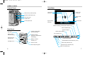
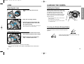
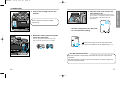
Page 1
DETAILED OPERATION
BASIC OPERATION
2/3/99 2:44 PM
E
INSTRUCTION MANUAL
APPENDIX
MAXXUM9E
MAXXUM9E
2/3/99 2:44 PM
Page 2
FOR PROPER AND SAFE USE
The ultimate tool for creative professionals and advanced amateurs alike, the
Maxxum / Dynax 9 has been designed with precission in mind to help you capture
your photographic vision. As you use the Maxxum / Dynax 9, you will find that its
performance and reliability compliment your own photographic expertise and in
raising your skills to a higher level.
In addition to its high durability zinc and stainless steel body, the Maxxum / Dynax 9
boasts the following features:
• A top shutter speed of 1/12,000 sec. and top x-sync speed of 1/300 sec.
• High speed autofocus with omni-dimensional Predictive Focus Control
and a maximum framing rate of 4.5 frames/sec with autofocus tracking
in continuous focus mode. (5.5 frames/sec in manual focus mode)
• 100% viewfinder
• 1/3 and 1/2 EV exposure compensation increments.
• Data Memory storage of exposure information.
• 21 Custom Functions to tailor the camera to your personal shooting style
This manual has been designed to help you understand the operation of your
camera and its functions. Please familiarize yourself with the names of the controls
and their locations on the camera, then read the Getting Started and Basic
Operation sections. Once you’ve mastered basic operation, move on to the Detailed
Operation section to expand your expertise.
This device complies with Part 15 of the FCC Rules. Operation is subject to the following two conditions: (1) This device may not cause harmful interference, and (2) this device must accept any interference received, including interference that may cause undesired operation. Changes or modifications not approved by the party responsible for compliance could void the user's authority to operate
the equipment. This equipment has been tested and found to comply with the limits for a Class B digital device, pursuant to Part 15 of the FCC Rules. These limits are designed to provide reasonable
protection against harmful interference in a residential installation. This equipment generates, uses
and can radiate radio frequency energy and, if not installed and used in accordance with the instructions, may cause harmful interference to radio communications. However, there is no guarantee that
interference will not occur in a particular installation. If this equipment does cause harmful interference
to radio or television reception, which can be determined by turning the equipment off and on, the
user is encouraged to try to correct the interference by one or more of the following measures:
• Reorient or relocate the receiving antenna.
• Increase the separation between the equipment and the receiver.
• Connect the equipment to an outlet on a circuit different from that to which the receiver is
connected.
• Consult the dealer or an experienced radio/TV technician for help.
Read and understand all warnings and cautions before using this product.
WARNING
Batteries may become hot or explode due to improper use.
•
•
•
•
•
•
Use only the batteries specified in this instruction manual.
Do not install the batteries with the polarity (+/–) reversed.
Do not subject batteries to fire or high temperatures.
Do not attempt to recharge, short, or disassemble.
Do not mix batteries of different types, brands, or ages.
Follow local regulations for battery disposal. Tape over lithium battery contacts before
disposal.
Use caution, accidents may occur when using this product near young children.
Keep batteries and other things that could be swallowed away from young children.
Contact a doctor immediately if an object is swallowed.
Immediately remove the batteries and discontinue use if…
• the camera is dropped or subjected to an impact in which the interior is exposed.
• the camera emits a strange smell, heat, or smoke.
Do not disassemble. Electric shock may occur if a high voltage circuit inside the
camera is touched. Take your camera to a Minolta Service Facility when repairs are
required.
Do not look directly at the sun through the viewfinder.
CAUTION
Do not allow a camera lens to point directly at the sun. Fire may occur if sunlight
comes to focus on a flammable surface. Replace the lens cap when the product is
not being used.
This mark on your camera certifies that this camera meets the requirements of
the EU (European Union) concerning interference causing equipment regulations.
CE stands for Conformité Européenne (European Conformity).
This Class B digital apparatus complies with Canadian ICES-003.
1
MAXXUM9E
2/3/99 2:44 PM
Page 2
TABLE OF CONTENTS
Table of Contents ....................................2
Names of Parts .......................................4
GETTING STARTED
Strap........................................................8
Diopter Adjustment .................................9
Batteries ................................................10
Lens.......................................................12
Handling the Camera ............................13
BASIC OPERATION
Loading Film..........................................15
Taking Pictures in Full-Auto ..................18
Focus Signals ....................................19
Special Focus Situations.......................20
Focus Hold ............................................21
Using the Built-in Flash
Operation ...........................................22
Flash Signals .....................................22
Flash Range ......................................23
Lens Shadowing ................................23
Rewinding the Film
Automatic Rewind..............................24
Manual Rewind..................................24
FOCUS
Predictive Focus Control .......................27
Autofocus Modes ..................................28
Wide Focus Area...................................30
Local Focus Area ..................................31
AF Lock .................................................32
Manual Focus........................................33
AF Illuminator ........................................34
EXPOSURE
P-Mode..................................................36
A-Mode..................................................37
S-Mode..................................................39
M-Mode .................................................41
METERING
Selectable Metering
14 Segment Metering ........................45
Spot Metering ....................................46
Center Weighted Metering.................47
AE Lock.................................................48
Exposure Compensation.......................50
Setting the ISO Manually ......................52
DRIVE
Advance Mode ......................................54
Self Timer ..............................................56
Exposure Bracketing .............................58
Multiple Exposure..................................60
FLASH
Four-Segment Flash Metering ..............63
Slow Sync .............................................64
Rear-Flash Sync ...................................65
High Speed Sync ..................................66
ADDITIONAL FEATURES
Eye-Start ...............................................76
Depth-of Field Preview..........................77
Taking Time Exposures .........................78
Remote Release Terminal.....................80
PC Terminal...........................................81
Data Panel Illuminator...........................82
SPECIAL FUNCTIONS
Data Memory
Selecting ............................................84
Overwriting.........................................86
Recalling Data ...................................87
Deleting Stored Data .........................90
Accessory Information..........................104
Exposure Warnings ..............................106
Trouble Shooting ..................................108
Care and Storage.................................110
DETAILED OPERATION
APPENDIX
2
Flash Compensation .............................67
Flash Bracketing ...................................68
Wireless/Remote Off-Camera Flash .....70
Custom Functions
Setting................................................91
Details................................................92
Specifications .......................................112
3
MAXXUM9E
2/3/99 2:44 PM
Page 4
NAMES OF PARTS
For information on specific parts, refer to the page numbers shown in parenthesis.
Diopter
adjustment dial (9)
Accessory shoe
Body
Built-in flash* (22-23)
Drive-mode lever (54)
AF Illuminator /
Self-timer lamp
(34, 56)
Exposurecompensation
dial lock (50)
Exposurecompensation
dial (50)
Viewfinder*
Exposure
mode dial (36-43)
Flash
compensation
dial (67)
Dirve mode
dial (54-61)
Eyepiece shutter
lever (79)
Data Panel
Flashcompensation
dial lever (67)
Main switch
Shutter-release
button
Eyepiece cup
Data-panel
illuminator (82)
Front
control dial
PC terminal
(81)
Film window
Rear control dial
Strap eyelet
Eyepiece
sensor* (76)
Lens contacts*
Remote-control
terminal (80)
AE-lock button (48)
Grip sensor (76)
Mounting
index
Mirror*
Depth-of-field
preview button (77)
Lens mount (12)
Lens release (12)
Focus-mode switch (33)
Back-cover
release (15)
AF mode dial (28)
Eye-start switch (76)
Metering-mode
switch (45-47)
AF button (32)
Flash-mode switch
Battery-chamber lock (10)
Battery-chamber door (10)
Vertical control grip contacts
(104)
* Do not touch
4
Tripod socket
5
MAXXUM9E
2/3/99 2:44 PM
Page 6
NAMES OF PARTS
Control Panel
Viewfinder
Data-memory button (84-90)
Spot-focus
area (95)
Local focus
areas (31)
Manual-rewind button (24)
Meter index
(42)
ISO button (52)
Adjust button
Control-panel door
Focus frame
Spot-metering
area (46)
Frames remaining counter (last 9 frames only)
AE-lock indicator (48)
Data Panel
ISO mark
Data memory
indicator (84-90)
Release priority
indicator (92)
Aperture display
Shutter speed display
(Focus area/ISO)
Shutter speed display
Focus signals (19)
Aperture display
(Exposure compensation
/Bracketing)
Battery condition
indicator (11)
Cartridge mark
Frame counter
Film transport signals
Focus-area indicator
Wireless/Remote flash indicator (70-74)
Flash ready indicator (22)
High-speed sync indicator (66)
Flash on indicator (22)
6
7
MAXXUM9E
2/3/99 2:44 PM
Page 8
Turn the diopter adjustment dial to compensate the eyepiece for near or far sighted
vision problems. The adjustment range is from –3 to +1 diopters.
GETTING
STARTED
Before attaching the lens…
Look through the viewfinder at a well illuminated blank
wall or clear blue sky.
Turn the diopter-adjustment dial until
the focus frame appears sharpest.
Farsighted users – turn the dial
clockwise.
Nearsighted users – turn the dial
counter-clockwise.
Attaching the Strap
Use the upper eyelets if you want the camera to
hang horizontally. Use the side eyelets if you
want the camera to hang vertically.
If additional correction is needed, attach a Minolta Eyepiece
Corrector (optional accessory) to the camera’s eyepiece.
Attach the strap through the strap
eyelets as shown. Pull firmly on the
strap to make sure it is secure.
9
GETTING STARTED
DIOPTER ADJUSTMENT
MAXXUM9E
2/3/99 2:44 PM
Page 10
Installing the Batteries
Checking Battery Power
Your camera uses two 3V CR123A lithium batteries to supply power for all camera
operations.
1. Lift and turn the battery-chamber
lock to OPEN, then open the batterychamber door.
The battery condition indicator displays the power status of the batteries when the
main switch is set to ON.
Full-battery symbol
Power is sufficient for all camera operations.
Low-battery symbol
2. Insert the batteries as indicated by
the + and – marks.
Power is low, but all functions are operational. Keep a
fresh battery handy.
Blinking low-battery symbol
Power is extremely low. The batteries will need to be
replaced soon. Flash recycling time may be slow.
3. Close the battery-chamber door,
then press and turn the batterychamber lock to CLOSE.
Blinking low-battery symbol appears alone
and the shutter locks.
Power is insufficient for camera operation. Replace the
batteries.
No display
Power is too low for the camera to operate. Replace
the batteries or make sure they have been inserted
correctly.
10
11
GETTING STARTED
BATTERIES
2/3/99 2:44 PM
Page 12
LENS
HANDLING THE CAMERA
Attaching the Lens
Holding the Camera
1. Remove the body and rear lens
caps.
2. Align the mounting indexes.
3. Insert the lens into the mount and
turn it clockwise until it clicks into
the locked position.
• Do not press the lens release when mounting the
lens. The lens will not couple properly.
GETTING STARTED
MAXXUM9E
Grip the camera firmly with your right hand,
while supporting the lens with your left. Keep
your elbows at your side and your feet
shoulder-width apart to hold the camera
steady. Keep the camera strap around your
neck or wrist in the event you accidentally
drop the camera.
• Do not touch the end of the lens barrel while
taking a picture.
• Do not block the AF illuminator.
• Use a tripod when using slow shutter speeds
or a telephoto lens.
Pressing the Shutter-Release Button
Press the shutter-release button partway down to
activate the camera’s autofocus and auto-exposure
systems.
Removing the Lens
1. Press the lens release and turn the
lens counter-clockwise until it stops.
Gently press the shutter-release button all the way
down to take the picture.
2. Remove the lens and replace the
caps, or attach another lens.
Caution
• Do not force the lens if it does not turn smoothly.
• Do not touch the inside of the camera, especially the lens contacts and
mirror.
12
13
2/3/99 2:44 PM
Page 14
LOADING FILM
Check the film window before loading film. If film is loaded, do not open the back
cover. Refer to Manual Rewind on page 24 to remove a partially exposed roll.
• Load film in the shade to reduce the chances of fogging the film.
• Do not use Polaroid Instant 35mm film. Winding problems may occur.
Before loading film for the first time…
Remove and discard the film gate protector.
BASIC
OPERATION
1. Turn the back-cover release counterclockwise to open the back cover.
The shutter curtain’s precision design makes it
extremely sensitive to pressure. Never touch it
with your fingers or the film tip.
Continued on the following page
15
BASIC OPERATION
MAXXUM9E
MAXXUM9E
2/3/99 2:44 PM
Page 16
2. Insert a film cartridge into the film
chamber.
4. Close the back cover and turn the
main switch to ON.
• The camera automatically advances the film to
the first frame. 1 will appear in the frame counter.
• The correct ISO for DX-coded film is set
automatically.
Refer to page 93 to reload a partially
exposed roll.
The ISO is displayed in the data panel
for 5 seconds after loading.
3. Extend the leader between the guide
rails to the index mark.
• If the film tip extends beyond the index mark,
push the excess film back into the cartridge.
blinks in the frame counter and the shutter locks
when the film is loaded incorrectly. Repeat steps 1 – 4.
Non DX Coded Film Notes…
Non-DX-coded film is automatically rewound at the end of the roll or after 36
exposures.
Non-DX-coded film is set to the ISO from the previous roll. Refer to page 52 to
set the film speed manually.
16
17
BASIC OPERATION
LOADING FILM
MAXXUM9E
2/3/99 2:44 PM
Page 18
3. Center your subject in the focus
frame, then press the shutter-release
button partway down.
1. Turn the main switch to ON.
• The local-focus area LED appears briefly
indicating the focus area selected by the camera.
2. Set Full-Auto mode as shown.
4. When
or
appears in the viewfinder, press the shutterrelease button all the way down to take the picture.
• The AF illuminator fires in low-light situations to assist the autofocus system (p.34).
• Use focus hold (p.21) if your subject is outside the focus frame.
• The number of frames remaining is displayed in the viewfinder for the last 9 frames on the
roll. The countdown does not appear for non-DX coded film.
Focus Signals
The following signals appear in the viewfinder data panel to indicate the focus
status when the shutter-release button is pressed partway down.
Focus is confirmed.
Set
Set
Set
Set
Set
Set
Set
18
the exposure mode dial to P.
the drive mode dial to single frame advance (S).
the metering-mode switch to
.
focus-mode switch to autofocus (AF).
the AF-mode dial to automatic autofocus (A).
the flash-compensation dial to 0.
the exposure-compensation dial to 0.
Continuous autofocus – Focus is confirmed.
Continuous autofocus – Lens focusing. Shutter is locked.
Focus cannot be confirmed – Shutter is locked.
Subject is too close or is one of the special focus situations
described on page 20.
19
BASIC OPERATION
TAKING PICTURES IN FULL–AUTO
2/3/99 2:44 PM
Page 20
SPECIAL FOCUS SITUATIONS
The camera may not be able to focus in situations like those described below.
When the focus signal blinks, use focus hold (p.21) or manual focus (p.33). See
page 19 for an explanation of the focus signals.
If the subject within the focus frame is
very bright, or low in contrast.
FOCUS HOLD
Use focus hold when your subject is outside the
focus frame or when autofocus is difficult to
confirm.
BASIC OPERATION
MAXXUM9E
• Use AF Lock (p. 32) to lock focus on moving
subjects.
• Focus hold does not operate when continuous
autofocus mode (p.29) is selected. Use AF Lock.
Focus hold cannot be used for moving subjects.
1. Center your subject in the focus
frame, then press the shutter-release
button partway down.
If two subjects at different distances
overlap in the focus frame.
If a subject composed of alternating
light and dark lines completely fills
the focus frame.
If your subject is near a very bright
object or area.
20
•
appears in the viewfinder when focus is
confirmed.
• Focus hold also locks the exposure settings when
14 segment metering is selected (p. 45).
2. Continue to hold the shutter-release
button partway down while you
compose your picture.
3. Press the shutter-release button the
rest of the way down to take the
picture.
• Remove your finger from the shutter-release
button to cancel focus hold.
21
MAXXUM9E
2/3/99 2:44 PM
Page 22
USING THE BUILT-IN FLASH
When up, the built-in flash fires every time the shutter is released to provide
coverage for focal lengths as wide as 24mm. Flash output is automatically
controlled by the camera’s TTL flash metering system.
•
.
will appear in the viewfinder data panel.
Slide the flash-mode switch to
to reduce the redeye effect when using the built-in flash.
• Red-eye reduction mode is only available with the built-in
flash.
2. Grip both sides of the flash and lift.
appears in the viewfinder when the flash is
fully charged.
• The shutter can not be released until the flash is
charged.
The range of the built-in flash depends on the speed of the film and the selected
aperture. Make sure your subject is within the flash range specified in the table
below.
Make sure you are at least 1m (3.3 ft.) from your subject
when using the built-in flash.
Aperture
f/2.8
f/3.5
f/4
•
- Push the flash down to turn it off.
Flash Signals
The following signals appear in the viewfinder data panel to indicate the flash status
when the shutter-release button is pressed partway down.
Flash will fire when the shutter is released.
Flash is charged.
BASIC OPERATION
1. Slide the flash mode switch to
Flash Range
f/5.6
ISO 100
ISO 200
ISO 400
1.0 ~ 4.3m
(3.3 ~ 14.1 ft.)
1.0 ~ 3.4m
(3.3 ~ 11.2 ft.)
1.0 ~ 3.0m
(3.3 ~ 9.8 ft.)
1.0 ~ 2.1m
(3.3 ~ 6.9 ft.)
1.0 ~ 6.1m
(3.3 ~ 20.0 ft.)
1.0 ~ 4.8m
(3.3 ~ 15.7 ft.)
1.0 ~ 4.2m
(3.3 ~ 13.8 ft.)
1.0 ~ 3.0m
(3.3 ~ 9.8 ft.)
1.0 ~ 8.6m
(3.3 ~ 28.2 ft.)
1.0 ~ 6.8m
(3.3 ~ 22.3 ft.)
1.0 ~ 6.m
(3.3 ~ 19.7 ft.)
1.0 ~ 4.3m
(3.3 ~ 14.1 ft.)
Lens Shadowing
Lens shadowing occurs when the lens or lens hood blocks part of the output from
the built-in flash. Lens shadowing appears as semi-circular shaded area at the
bottom (horizontal) or side (vertical) of your image.
• Remove the lens hood before using the built-in flash.
• Lens shadowing may occur with the following lenses at shorter focal
lengths.
AF Zoom 17-35mm f/3.5G
AF Zoom 28-70mm f/2.8G
AF Zoom 28-85mm f/3.5-4.5
AF Zoom 28-135mm f/4-4.5
• The built-in flash can not be used with the following lenses:
AF 300mm f/2.8 (APO tele)
AF 600mm f/4 (APO tele)
Previous exposure was correct.
22
23
MAXXUM9E
2/3/99 2:44 PM
Page 24
REWINDING THE FILM
Automatic Rewind
The film is automatically rewound after the last frame is exposed (or 36 exposures).
When the film is completely rewound, the motor will stop and
will blink in the
data panel indicating it is safe to open the back of the camera.
1. Wait until the film is completely rewound.
will appear and
will blink in the data panel.
2. Open the back cover and remove the film.
3. Close the back cover.
Manual Rewind
Use manual rewind to rewind the film before the current roll is finished.
1. Open the control panel door, then
press the manual-rewind button.
2. Follow steps 1-3 from Automatic
Rewind.
Custom Function Notes
Automatic (1) or manually initiated (2) rewind (p.92).
Rewind the leader into the cartridge (1)
or leave the leader out (2) (p.92).
Fast or slow/silent rewind (p.97).
24
DETAILED
OPERATION
DETAILED OPERATION
•
2/3/99 2:45 PM
Page 26
FOCUS - Predictive Focus Control
Predictive Focus Control determines the
subject’s speed, position, and acceleration
changes from the focus sensor data, then sets
the best focus at the predicted point of
exposure.
Predictive focus control is always active in the
Automatic and Continuous autofocus modes.
FOCUS
With the ability to track acceleration in all
three dimensions, Predictive Focus Control
makes it possible for the camera to calculate
where your subject will be when the shutter
opens.
FOCUS
MAXXUM9E
27
MAXXUM9E
2/3/99 2:45 PM
Page 28
FOCUS — Autofocus Modes
Selecting the Autofocus Mode
1. Set the focus mode switch to AF.
2. Turn the AF mode dial to the desired
mode.
Continuous Autofocus (C)
Use Continuous Autofocus when shooting sporting events or when you know
the subject will be in constant motion.
Center your subject in the focus frame,
then press the shutter-release button
partway down to activate autofocus.
The camera continues to focus as long
as the shutter-release button is
pressed partway down.
Automatic Autofocus (A)
Designed to work well in almost any situation, Automatic Autofocus is especially
suited to moving subjects that stop suddenly.
Center your subject in the focus frame,
then press the shutter-release button
partway down to activate autofocus.
The camera will continue focusing
while the subject is moving, then lock
focus when the subject is still.
28
FOCUS
• The AF Illuminator (p.34) does not operate in
Continuous Autofocus mode.
• The focus area is not displayed unless the AF
button is pressed.
Single Shot Autofocus (S)
Use Single-shot AF when photographing non-moving subjects or to lock focus
on subjects outside the focus area.
Center your subject in the focus frame,
then press the shutter-release button
partway down to activate autofocus.
Once confirmed, focus remains locked
until pressure is removed from the
shutter-release button or the shutter is
released.
29
MAXXUM9E
2/3/99 2:45 PM
Page 30
FOCUS — Focus Area
Wide Focus Area
Local Focus Area
The camera’s standard focus mode, wide focus
area uses the camera’s three focus sensors to
automatically focus on your subject. Wide focus
area’s greater framing flexibility makes it easier
for the camera to focus on moving subjects.
•
Select a local focus area for greater control over the focus location in the autofocus
mode.
• Only the center focus area can be selected when the RF 500mm or the AF Power Zoom
35-80mm is mounted.
1. Press the AF button and turn the
front control dial to select the
desired local focus area.
appears in the viewfinder data panel when
wide focus area is selected.
• The local focus area is displayed in the focus
frame and data panels.
FOCUS
The camera determines which sensor is focusing on
your subject and sets the focus accordingly.
2. Release the AF button when the
desired local focus area appears.
The selected focus area momentarily
appears in the viewfinder frame when the
shutter release button is pressed partway
down.
• The focus-area indicator displays the currently
selected focus area.
• The focus area LEDs do not appear when
continuous autofocus (p.29) is selected.
Custom Function Notes
Wide / Local Focus Area (1) or Spot Focus (2) when the AF button
is pressed (p.96).
30
31
MAXXUM9E
2/3/99 2:45 PM
Page 32
FOCUS — AF Lock
FOCUS — Manual Focus
Press the AF button to lock focus on moving or stationary subjects using the current
focus mode. The focus remains locked until the AF button is released.
• Exposure is also locked if 14-segment metering (p.45) is selected.
• Pressing the AF button also activates the AF illuminator.
1. Center your subject in the focus
frame.
Focus the lens manually when autofocus is not suitable and focus hold is not
possible. The autofocus system will monitor focus and indicate when a subject in
the focus frame is in focus.
• Only the center weighted average (p. 47) and spot (p. 46) metering modes are available in
manual focus mode.
• 14-segment honeycomb pattern metering (p. 45) is changed to center weighted average
metering when manual focus mode is selected.
1. Slide the focus-mode switch to M.
• The current local focus area LED appears in the
viewfinder data panel until the AF button is
released.
• The exposure settings do not appear until the
shutter-release button is pressed partway down.
2. Turn the focusing ring until your
subject appears sharp and focused.
•
appears in the viewfinder when the subject in
the focus frame is in focus.
Turn the front control dial to select a different
local focus area.
3. Recompose the scene as desired,
then take the picture.
AF Power Zoom and xi-Series Lenses
Pull and turn the zoom ring until your
subject appears sharp.
32
33
FOCUS
2. Press and hold the AF button.
MAXXUM9E
2/3/99 2:45 PM
Page 34
FOCUS — AF Illuminator
In low-light / low subject contrast situations, the
AF illuminator automatically projects a pattern
of lines onto the subject for the camera’s AF
sensors to focus on.
34
Do not to obstruct the AF illuminator.
Pressing the AF button (p.32) also activates the AF illuminator.
The range of the AF Illuminator is 0.7 – 7.0 meters (2.3 – 23.0 ft.).
The AF illuminator will not fire in continuous autofocus mode.
The AF illuminator may not operate with 300mm or longer single focal length lenses.
The AF illuminator will not operate with 3x-1x Macro Zoom.
When an accessory flash is attached, its AF illuminator may be active in place of the
camera’s AF illuminator.
EXPOSURE
EXPOSURE
•
•
•
•
•
•
•
MAXXUM9E
2/3/99 2:45 PM
Page 36
EXPOSURE — P-Mode
Select P-mode (Programmed Autoexposure) when you want to give your full
attention to your subject and composition. The Program mode software analizes the
subject’s size, motion, and magnification as well as the focal length of your lens,
then sets the shutter speed and aperture according to the requirements of the
scene.
1. Set the exposure-mode dial to P.
EXPOSURE — A-Mode
In A-mode (Aperture Priority), you select the aperture and the camera automatically
sets the shutter speed required for proper exposure. Set the camera to A-mode
when you want to control the range of focus (depth-of-field) in an image.
Press the depth of field button to confirm the range
of focus in your image (p.77).
2. Compose your scene, focus, and
take the picture.
2. Turn either control dial to select the
aperture.
P-Mode Flash
• The aperture setting changes in 1/2 or 1/3 EV
increments depending on the position of the
exposure compensation dial. See page 51.
When the built-in flash is up or an attached accessory flash is on, it will fire each
time the shutter is released. The camera’s TTL automatic flash metering system will
ensure proper exposure.
• Make sure your subject is within the flash range (p.23).
Custom Function Notes
Setting 2 - PA/Ps mode (p.101). This mode lets you override the
exposure settings selected by the camera in P mode.
36
If 12000 or 30” blinks in the viewfinder and
the data panel, the required setting is beyond
the camera’s shutter speed range. Turn the
control dial until the blinking stops.
37
EXPOSURE
1. Turn the exposure-mode dial to A.
MAXXUM9E
2/3/99 2:45 PM
Page 38
EXPOSURE — S-Mode
EXPOSURE — A-Mode
A-mode flash
When the built-in flash is up or an attached accessory flash is on, it will fire each
time the shutter is released. The camera’s TTL automatic flash metering system will
ensure proper exposure.
In S-mode (Shutter Priority), the camera automatically sets the aperture for the
selected shutter speed. Use S-mode when you want to control the blur caused by
subject movement.
1. Turn the exposure-mode dial to S.
1. Raise the built-in flash.
•
appears in the viewfinder when the flash is
charged.
• The shutter speed is automatically set to 1/300 or
slower.
2. Turn either control dial to select the
shutter speed.
• The shutter speed changes in 1/2 or 1/3 EV
increments depending on the position of the
exposure compensation dial. See page 51.
EXPOSURE
2. Turn the control dial to select the
aperture.
• Refer to the Flash Range table on page 23 to
determine the range of the built-in flash at the
selected aperture.
If 300 blinks in the viewfinder and the data
panel, the light level is too bright for the
selected aperture. Turn the control dial until
the blinking stops or cancel the flash.
If the aperture display in the viewfinder and
the data panel blinks, the required setting is
outside the aperture range of the lens. Turn
the control dial until the blinking stops.
Push the built-in flash down or turn the accessory flash off to cancel
the flash.
38
39
MAXXUM9E
2/3/99 2:45 PM
Page 40
EXPOSURE — M-Mode
EXPOSURE — S-Mode
S-mode Flash
When the built-in flash is up or an attached accessory flash is on, it will fire each
time a picture is taken. Flash exposure is controlled by the camera’s TTL automatic
flash metering system.
M-mode gives you full control of the exposure. The camera’s meter index displays
how your settings compare to the exposure determined by the camera’s metering
system.
• The aperture and shutter speed settings change in 1/2 or 1/3 EV increments depending
on the current exposure compensation dial setting.
1. Raise the built-in flash.
•
1. Turn the exposure-mode dial to M.
appears in the viewfinder when the flash is
charged.
2. Turn the front control dial to select
the shutter speed.
3. Turn the rear control dial to select
the aperture.
EXPOSURE
2. Turn the control dial to select any
shutter speed up to 1/300th of a
second.
• The camera sets the required aperture
automatically.
Manual Shift
Manual shift lets you shift to equivalent aperture/shutter speed combinations
without changing the exposure value (EV).
Push the built-in flash down or turn the accessory flash off to cancel
the flash.
40
Press the AE-lock button and turn the
front control dial until the desired
aperture / shutter speed combination
appears in the data panel.
41
MAXXUM9E
2/3/99 2:45 PM
Page 42
EXPOSURE — M-Mode
Metering in Manual Mode
The meter index displays the EV difference between your settings and the ‘correct’
exposure determined by the camera. The 0 position (null point) represents the
recommended exposure using the currently selected metering pattern (pp.45-47).
• The EV scale is marked in 1/2 or 1/3EV increments depending on the current setting of
the exposure compensation dial (p.51).
• A second indicator will appear in the meter index to indicate the new null point if the
exposure compensation dial is set to a value other than 0.
M-mode Flash
When the built-in flash is up or an attached accessory flash is on, it will fire each
time the shutter is released. The camera’s TTL flash metering system will ensure
correct exposure.
1. Raise the built-in flash.
•
appears in the viewfinder when the flash is
charged.
Your settings will overexpose the
metered area by 1EV.
Your settings will underexpose the
metered area by 1.5EV.
2. Turn the front control dial to select
any shutter speed up to 1/300th of a
second.
3. Turn the rear control dial to select
the desired aperture.
• Refer to the flash range table on page 23 to
determine the range of the built-in flash at the
selected aperture.
or
will blink in the meter index if the
settings will over or underexpose the subject
by more than 3.0EV.
42
43
EXPOSURE
Your settings match the recommended
exposure.
2/3/99 2:45 PM
Page 44
METERING — Selectable Metering
14 Segment Honeycomb Pattern Metering
Fourteen-Segment Honeycomb-Pattern Metering uses information from the
autofocus system to set the metering pattern according to the position of the main
subject. The light metered by each applicable segment is then evaluated to
determine the degree of spot-lighting or backlighting present in your scene. The
local focus-area (LED) momentarily displays the sensor being used when the
shutter release button is pressed partway down.
Fourteen-Segment Honeycomb-Pattern Metering is the camera’s standard
metering mode and is appropriate for most photographic situations.
METERING
Selecting 14 Segment Honeycomb Pattern Metering
Turn the metering mode switch to
.
METERING
MAXXUM9E
45
MAXXUM9E
2/3/99 2:45 PM
Page 46
METERING — Selectable Metering
Spot Metering
Center Weighted Average Metering
Spot metering uses only the center honeycomb segment to meter the image.
• The spot-metering area indicates the metering area.
Selecting Spot Metering
Center-weighted average mode bases the exposure on an average of the readings
from each of the honeycomb segments - with emphasis placed on the center of the
image.
Care should be taken when photographing backlit, spotlit, or off-center subjects as
non-subject areas may be included in the exposure calculation.
Selecting Center Weighted Average Metering
Turn the metering mode switch to
.
.
METERING
Turn the metering mode switch to
46
47
MAXXUM9E
2/3/99 2:45 PM
Page 48
METERING — Automatic Exposure Lock (AEL)
Press the AE-lock button to lock the exposure
using the currently selected metering pattern
without locking the focus. The exposure
remains locked until the AE-lock button is
released.
4. Recompose the scene as desired.
• The meter index indicators display the EV
difference between the locked exposure and the
exposure for the subject area currently inside the
spot metering area.
• Pressing the AE-lock button sets the flash to
slow sync mode (p.64).
• The second indicator in the exposure index does
not appear when slow sync is selected.
Current Reading
1. Select the desired metering pattern
(pp.45-47).
2. Meter the area on which you want
to lock the exposure.
5. Press the shutter-release button allthe-way down to take the picture.
Custom Function Notes
3. Press and hold the AE-lock button.
• AEL appears in the viewfinder.
48
Setting 2.
Press the AE-lock button once to activate Automatic Exposure
Lock. Press again to cancel.
49
METERING
Locked Exposure (0)
MAXXUM9E
2/3/99 2:45 PM
Page 50
METERING – Exposure Compensation
Especially helpful when using the spot or
center weighted metering patterns, exposure
compensation lets you manually adjust the
metered exposure +/– 3 EVs in 1/2 or +/– 2
EVs in 1/3 EV increments.
Changing to 1/3 EV Increments
1. Set the exposure compensation dial to +/– 0 EV.
2. Pull the exposure-compensation
dial up, then rotate it 180°.
• The camera may be damaged if the exposure
compensation dial is not set to 0 EV before
pulling it up.
Compensated Exposure
More exposure is recommended when the scene is
primarily white tones.
Less exposure is recommended when the scene is
composed of darker tones or shadows.
The effect is most visible when slide film is being used.
1. Unlock the exposure compensation dial.
Exposure compensation
dial lock
3. Set the exposure compensation dial down
at 0 on the 1/3 EV increment side.
METERING
Metered Exposure
• The exposure may be incorrect if the exposure
compensation dial is not seated properly.
• The meter index scale changes to 1/3EV increments.
• Shutter speed and aperture will change in 1/3 EV
increments.
4. Set the desired compensation value.
Custom Function Notes
Select setting 3 to change the exposure compensation value using
the rear control dial in A, S, and P modes.
2. Rotate the exposure compensation
dial to the desired compensation
value.
• The compensation value is indicated in the meter
index.
50
• A +/– 3 EV range is available for 1/3 EV increments in this setting.
Select setting 2 to view the exposure compensation value in the
data panel when the exposure compensation dial is set to a value
other than 0.
51
MAXXUM9E
2/3/99 2:45 PM
Page 52
METERING — Setting the ISO Manually
Set the ISO manually to override the DX-coded ISO or when using non-DX coded
film.
• Non-DX coded film is initially set to the previous roll’s ISO.
Film must be loaded before the ISO can be changed.
1. Open the control panel door and press the
ISO button.
2. Turn either control dial to set the
desired ISO value.
• The ISO can be changed manually from 6 to
6400 in 1/3 EV increments.
3. Press the shutter-release button
partway down to enter the new ISO.
Custom Function Notes
Setting 2 - DX Memory On (p.94).
Applies ISO changes to future rolls with the same DX-coded ISO.
52
DRIVE
DRIVE
MAXXUM9E
2/3/99 2:45 PM
Page 54
DRIVE – Advance Mode
This camera has both single frame and continuous advance drive modes. Select
single frame advance to expose and advance the film one frame at a time. Switch
to continuous drive to photograph dynamic action sequences at up to 5.5 frames
per second (4.5 frames per second in autofocus mode).
2. Turn either control dial to select
or
speed continuous drive.
• AF Zoom xi and Power zoom lenses cannot be
zoomed when continuous-advance mode is
selected.
• The shutter can not be released until the camera
has focused on your subject.
• The maximum drive speed changes depending on the focus mode.
• When the built-in flash is up or an accessory flash is on, the shutter can not be released
until the flash is charged.
Turn the drive-mode lever to the desired
drive mode.
S – Single Frame Advance
C – Continuous Advance
3. Press the shutter-release button
partway down to enter the
selection.
If continuous advance is selected…
1. Open the control panel door, then
press the adjust button.
HI
Lo
Single Shot AF (S)
5.5 fps
2 fps
Automatic AF (A)
4.5 fps
2 fps
Continuous AF (C)
4.5 fps
2 fps
Manual Focus (M)
5.5 fps
2 fps
DRIVE
Maximum Framing Rate
Focus Mode
• The maximum drive speed drops to 5 frames per second when Data Memory is activated.
• At drive speeds faster than 5 frames per second, the optional Quartz Data Back QD-9 will
imprint the date or time only on the first frame of a motor advanced series.
• The maximum drive speed is 4.5 fps when the Data Memory Back DM-9’s imprinting
function is activated.
Custom Function Notes
Switch to setting 2 for release priority operation (p.92).
• RP will appear in the data panel.
54
55
MAXXUM9E
2/3/99 2:45 PM
Page 56
DRIVE – Self-Timer
Use the self-timer to delay the shutter release for 2 or 10 seconds (approx.) after
the shutter-release button is pressed all the way down. In addition to delaying
release of the shutter, the 2 second delay pops the mirror up two seconds before
the shutter opens to reduce blur caused by camera vibration.
• The red-eye reduction flash mode is not effective when the 2 second self timer is
selected.
• Close the eyepiece shutter (p.79) to prevent a bright light source behind the camera from
interfering with the exposure.
1. Place the camera on a tripod, then turn
the drive-mode lever to .
5. Center your subject in the focus
frame, then press the shutterrelease button part way down to
confirm the focus.
• The shutter will be released even if the focus is
not confirmed.
6. Press the shutter-release button all
the way down to start the timer.
• Turn the main switch to LOCK
or select another drive mode to
cancel the 10 sec self timer.
(2 sec) –
2. Open the control panel door and
press the adjust button.
The mirror pops up when the
shutter release button is pressed
all-the-way down. The shutter is
released two seconds later.
• The 2 second self timer cannot
be cancelled.
3. Turn either control dial until the
desired delay appears in the data
panel.
4. Press the shutter-release button
partway down to enter the
selection.
56
57
DRIVE
(10 sec) – The self-timer indicator on the
front of the camera will blink
slowly, then blink rapidly just
before the shutter releases.