1
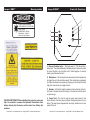
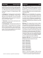
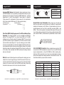
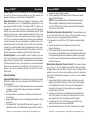
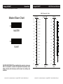
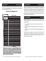
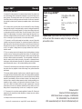
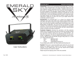
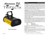
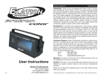
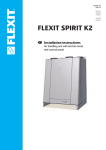
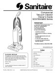
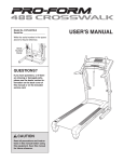
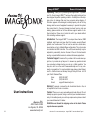
Image 8 DMX™
General Introduction
Unpacking: Thank you for purchasing the Image 8 DMX™ by American DJ®. Every Image 8 DMX™ has been thoroughly tested and has
been shipped in perfect operating condition. Carefully check the shipping carton for damage that may have occurred during shipping. If
the carton appears to be damaged, carefully inspect your unit for any
damage and be sure all equipment necessary to operate the system
has arrived intact. In the event damage has been found or parts are
missing, please contact our toll free customer support number for further instructions. Please do not return the unit to your dealer without
first contacting customer support.
Introduction: The Image 8 DMX™ is a unique three channel, DMX
intelligent, eight beam red laser effect that creates several different
patterns over a wide area. This unit can be used as a stand alone,
sound-active unit or in a Master/Slave configuration. The unit can also
be controlled via DMX controller. The unit’s sound sensitivity may be
adjusted by a sensitivity knob on the rear of the unit. For best results
use fog or special effects smoke to enhance the beams projections.
Customer Support: American DJ® provides a toll free customer support line, to provide set up help and to answer any question should
you encounter problems during your set up or initial operation. You
may also visit us on the web at www.americandj.com for any comments or suggestions. For service related issue please contact American DJ®. Service Hours are Monday through Friday 9:00 a.m. to 5:00
p.m. Pacific Standard Time.
Voice:
(800) 322-6337
Fax:
(323) 582-2610
E-mail:
[email protected]
Warning! To prevent or reduce the risk of electrical shock or fire, do
not expose this unit to rain or moisture.
User Instructions
Caution! There are no user serviceable parts inside this unit. Do not
American DJ®
5/03
4295 Charter Street
Los Angeles, CA. 90058
www.americandj.com
attempt any repairs yourself, doing so will void your manufactures warranty. In the unlikely event your unit may require service please contact
your nearest American DJ dealer.
PLEASE do not discard the shipping carton in the trash. Please
recycle when ever possible.
©American
DJ® - www.americandj.com - Image 8 DMX™ Instruction Manual Page 2
Image 8 DMX™
General Instructions
Please carefully read and understand the instructions in this manual
thoroughly before attempting to operate this unit. These instructions
contain important safety information regarding the use and maintenance of this unit. Please keep this manual with the unit, for future
reference.
CAUTION IMPORTANT! When installing this projector, make sure
that it is mounted in a manner that prevents the audience from
looking directly into the beam, and the beam from striking the
audience.
Image 8 DMX™
• 4.9mW Red Laser Diode
• 8 Seperate Lasers
• Sound Active with Internal Microphone
• DMX-512 Protocol Compatible
• 3 Channels
• Master/Slave Operation
• 14 Patterns
• Volume Sensitivity Knob
Features
Image 8 DMX™
Warranty Registration
The Image 8 DMX™ carries a 90 day limited warranty. Please fill out
the enclosed warranty card to validate your purchase. All returned
service items whether under warranty or not, must be freight pre-paid
and accompany a return authorization (R.A.) number. The R.A. number must be clearly written on the outside of the return package. A
brief description of the problem as well as the R.A. number must also
be written down on a piece of paper included in the shipping carton.
If the unit is under warranty, you must provide a copy of your proof of
purchase invoice. You may obtain a R.A. number by contacting our
customer support team on our toll free customer support number. All
packages returned to the service department not displaying a R.A.
number on the outside of the package will be returned to the shipper.
©American
DJ® - www.americandj.com - Image 8 DMX™ Instruction Manual Page 3
Image 8 DMX™
!
Safety Precautions
!
Safety Issues: This unit may pop the breaker if the maximum allotted
load of 2 amps is reached.
• To reduce the risk of electrical shock or fire, do not expose this unit
rain or moisture.
• Do not spill water or other liquids into or on to your unit.
• Do not attempt to remove or break off the ground prong from the
electrical cord. This prong is used to reduce the risk of electrical
shock and fire in case of an internal short. Do not attempt to operate this unit if the power cord has been frayed or broken.
• Disconnect from main power before making any type of connection.
• Do not remove the cover under any conditions. There are no user
serviceable parts inside.
• Always be sure to mount this unit in an area that will allow proper
ventilation. Allow about 6” (15cm) between this device and a wall.
• Do not attempt to operate this unit, if it becomes damaged.
• This unit is intended for indoor use only, use of this product outdoors voids all warranties.
• During long periods of non-use, disconnect the unit’s main power.
• Always mount this unit in safe and stable matter.
• Power cords should be routed so they are not likely to be walked
on, pinched by items placed upon or against them.
• Cleaning -The fixture should be cleaned only as recommended by
the manufacturer. See page 6 for cleaning details.
• Heat -The appliance should be situated away from heat sources
such as radiators, heat registers, stoves, or other appliances
(including amplifiers) that produce heat.
• The fixture should be serviced by qualified service personnel when:
A. The power-supply cord or the plug has been damaged.
B. Objects have fallen on, or liquid has been spilled into the unit.
C. The unit has been exposed to rain or water.
D. The unit does not appear to operate normally or exhibits a
marked change in performance.
©American
DJ® - www.americandj.com - Image 8 DMX™ Instruction Manual Page 4
Image 8 DMX™
Warning Labels
Image 8 DMX™
Control & Functions
DANGER
1
VISIBLE LASER RADIATION
-AVOID DIRECT EYE EXPOSURE
LASER DIODE
WAVELENGTH : 532 nm
Max Output : <4.9mW
Class IIIa Laser Product
2
3
8
7
4
�
�
�
�
��
��
��
���
���
���
6
���������
5
1. Remote Contoller Input - This input uses a 1/4” (6.3mm) microphone jack. The optional blackout controller plugs in here and is used
to control the first unit, and other units if linked together. It controls
stand by and blackout function.
2. Microphone - This microphone receives external low frequencies
to trigger the unit in Sound-Active mode. This microphone is designed
to receive low frequency sounds only, tapping on the microphone and
high pitch sounds may not trigger the unit.
3. Breaker - A 2A built-in safety breaker to reduce the risk of electrical shock or fire and protect the circuitry. In the case of a internal short
or power surge.
CAUTION IMPORTANT! When installing this projector, make sure
that it is mounted in a manner that prevents the audience from
looking directly into the beam, and the beam from striking the
audience.
©American
DJ® - www.americandj.com - Image 8 DMX™ Instruction Manual Page 5
4. Power Cord - This cord is used to supply main power to the
fixture. Be sure the main power matches the required power of your
fixture. The rated power requirements are clearly marked on the rear
panel of the unit.
©American
DJ® - www.americandj.com - Image 8 DMX™ Instruction Manual Page 6
Image 8 DMX™
Control & Functions
5. Dip Switches - These switches serve two functions. In masterslave mode these switches are used to assign a specific head address.
In DMX mode these switches are used to assign a DMX address to the
unit. In DMX mode each switch corresponds to a specific value based
on binary code. See pages 8-9 for a detailed explanation of DMX
binary code.
6. XLR Output Jack - This female output jack is used to transmit the
incoming DMX signal to another DMX fixture, or transmit a Master/
Slave signal to the next Image 8 DMX™ in the chain. For best results
in DMX or Master/Slave mode terminate this jack if it is the last unit in
the chain. See “Terminator” on page 10.
7. XLR Input Jack - This male input jack is used to accept an incoming DMX signal or Master/Slave signal.
8. Audio Sensitivity Knob - This adjusts the audio sensitivity of the
internal microphone (1). Turning the sensitivity knob in the clockwise
direction will increase the sensitivity to sound. Turning the knob in
the counter clockwise direction will decrease the fixture’s sensitivity
to sound. If the knob is turned completely in the counter-clockwise
direction the sound sensitivity function will turn off.
Image 8 DMX™
Set Up
Power Supply: Before plugging your unit in, be sure the source
voltage in your area matches the required voltage for your American
DJ® Image 8 DMX.™ The American DJ® Image 8 DMX™ is 120v only.
Because line voltage may vary from venue to venue, you should be
sure your unit voltages matches the wall outlet voltage before attempting to operate you fixture.
DMX-512: DMX is short for Digital Multiplex. This is a universal protocol used as a form of communication between intelligent fixtures
and controllers. A DMX controller sends DMX data instructions from
the controller to the fixture. DMX data is sent as serial data that travels from fixture to fixture via the DATA “IN” and DATA “OUT” XLR terminals located on all DMX fixtures (most controllers only have a DATA
“OUT” terminal).
DMX Linking: DMX is a language allowing all makes and models of
different manufactures to be linked together and operate from a single controller, as long as all fixtures and the controller are DMX compliant. To ensure proper DMX data transmission, when using several
DMX fixtures try to use the shortest cable path possible. The order
in which fixtures are connected in a DMX line does not influence the
DMX addressing. For example; a fixture assigned a DMX address of 1
may be placed anywhere in a DMX line, at the beginning, at the end,
or anywhere in the middle. When a fixture is assigned a DMX address
of 1, the DMX controller knows to send DATA assigned to address 1
to that unit, no matter where it is located in the DMX chain.
Dipswitches in DMX mode: This unit uses dipswitches to assign a
DMX address. Each dipswitch represents a binary value.
Dipswitch 1 address equals 1
Dipswitch 2 address equals 2
Dipswitch 3 address equals 4
Dipswitch 4 address equals 8
Dipswitch 5 address equals 16
Dipswitch 6 address equals 32
Dipswitch 7 address equals 64
Dipswitch 8 address equals 128
Dipswitch 9 address equals 256
Dipswitch 10 - Some units omit dipswitch 10. When a unit does
include dipswitch #10, it is usually used for special functions such as
©American
DJ® - www.americandj.com - Image 8 DMX™ Instruction Manual Page 7
©American
DJ® - www.americandj.com - Image 8 DMX™ Instruction Manual Page 8
Image 8 DMX™
Set Up
Image 8 DMX™
sound activation.
REMOTE
CONTROL
INPUT
SOUND
Set DMX address 1:
Dip-switches # 1 = 1
INPUT
OUTPUT
Set DMX address 7:
Dip-switches #
2
OUTPUT
REMOTE
CONTROL
INPUT
SOUND
INPUT
POWER
3
OUTPUT
SOUND
POWER
DMX512 OUT
3-PIN XLR
2
3
DMX +
DMX -
3
1
2
DMX512 IN
3-PIN XLR
3
Figure 2
©American
1
2
OUTPUT
REMOTE
SOUND
3 Hot
Pin 1 = Ground
INPUT
OUTPUT
PinCONTROL
2
= Data Compliment (negative)
INPUT
3 Hot
Pin 3 = Data True (positive)
Figure 3
Special Note: Line Termination. When longer runs of cable are
used, you may need to use a terminator on the last unit to avoid erratic
behavior. A terminator is a 90-120 ohm 1/4 watt resistor which is connected between pins 2 and 3 of a male XLR connector (DATA + and
DATA -). This unit is inserted in the female XLR socket of the last unit
in your daisy chain to terminate the line. Using a cable terminator (ADJ
part number Z-DMX/T) will decrease the possibilities of erratic behavior.
3
1
2
DMX512 IN
3-PIN XLR
3
REMOTE
CONTROL
INPUT
INPUT
1
2
OUTPUT
POWER
Termination reduces signal errors and
avoids signal transmission problems
and interference. It is always advisable
to connect a DMX terminal, (Resistance
120 Ohm 1/4 W) between PIN 2 (DMX-)
and PIN 3 (DMX +) of the last fixture.
Figure 4
5-Pin XLR DMX Connectors. Some manufactures use 5-pin XLR
connectors for DATA transmission in place of 3-pin. 5-pin XLR fixtures
may be implemented in a 3-pin XLR DMX line. When inserting standard 5-pin XLR connectors in to a 3-pin line a cable adaptor must be
used, these adaptors are readily available at most electric stores. The
chart below details a proper cable conversion.
POWER
DMX+,DMX-,COMMON
cables. Do not
use the ground lug on the XLR connector. Do not connect the cable’s shield conductor to the ground lug or allow the shield
conductor to come in contact with the XLR’s outer casing. Grounding
the shield could cause a short circuit and erratic behavior.
COMMON
INPUT
XLR Pin Configuration
1 Ground
POWER
Notice: Be sureDMX512
to follow figures two and three when making your own
1
2 Cold
2 Cold
REMOTE
CONTROL
INPUT
SOUND
POWER
1
INPUT
1 Ground
1=1
2=2
3 DMX512
=4
DMX+,DMX-,COMMON
=7
Data Cable (DMX Cable) Requirements (For DMX and Master/Slave
Operation): The Image 8 DMX™ can be controlled via DMX-512
protocol. The Image 8 DMX™ is a three channel DMX unit. The DMX
COMMON
address is set on the side panel of the Image 8 DMX.™ Your unitDMX
and
+
DMX512 OUT
3-PIN XLR
your DMX controller require a standard 3-pin XLR
connector forDMX
data
input and data output (Figure 1). If you are making your own cables,
be sure to use standard two conductor shielded cable (This cable may
be purchased at almost all pro sound and lighting stores). Your cables
should be made with a male and female XLR connector on either end
of the cable. Also remember that DMX cable must be daisy chained
and can not be split.
REMOTE
CONTROL
INPUT
XLR Female Socket
XLR Male Socket
Assigning DMX Address: Each dipswitch has a preset value. A specific DMX address is set by combining the dipswitches that sum your
desired value. For example: To achieve a DMX address of 7, combine
dipswitches 1, 2, and 3. Since dipswitch 1 has a value of 1, dipswitch
2 has a value of 2, and dipswitch 3 has a value of 4, the combination
of the three create a DMX value of 7. (See example below).
SOUND
Set Up
3-Pin XLR to 5-Pin XLR Conversion
Conductor
3-Pin XLR Female (Out)
5-Pin XLR Male (In)
Ground/Shield
Pin 1
Pin 1
Data Compliment (- signal)
Pin 2
Pin 2
Pin 3
Pin 3
Termination reduces signal errors and
avoids signal transmission problems
Data True (+ signal)
and interference. It is always advisable
to connect a DMX terminal, (Resistance
Not Used
120 Ohm 1/4 W) between PIN 2 (DMX-)
and PIN 3 (DMX +) of the last fixture.
DJ® - www.americandj.com - Image 8 DMX™ Instruction Manual Page 9
Not Used
©American
Pin 4 - Do Not Use
Pin 5 - Do Not Use
DJ® - www.americandj.com - Image 8 DMX™ Instruction Manual Page 10
Image 8 DMX™
Operation
Power Supply: This unit is available only in 120v. Before plugging
your unit in be sure the source voltage in your area matches the
required voltage for your American DJ® Image 8 DMX.™
General Operation: This fixture is designed to operate as a stand
alone, sound-active unit, or in a Master/Slave configuration. It can
also operate via DMX controller. The Image 8 DMX™ is ready to be
plugged in out of the box. There is no power switch, after plugging
the unit into a power outlet the lasers will immediately begin to cycle
through the many built in patterns (provided dipswitch #10 is in the
“ON” position, and there is an ample amount of sound to trigger the
unit). The unit comes with several built-in patterns that automatically
cycle through when the unit is operating, the patterns may not be
selected manually. If the unit does not turn on after the unit has been
plugged in, be sure the breaker has not popped and the unit is properly plugged in to a matching wall outlet. If the problem continues to
persist, please contact customer support for further instructions.
Sensitivity Knob: A sound sensitivity knob is located on the rear
of the unit. Use this knob to regulate the amount of sound it takes to
trigger the unit. Turning the knob in a clockwise direction will increase
the units sensitivity to sound, turning the knob in a counterclockwise
direction will decrease the units sensitivity. Turning the knob completely to the counter-clockwise direction will turn off the soundactive mode.
Operating Modes:
Universal DMX Control: This mode allows you to use a universal
DMX-512 controller such as the American DJ® DMX Operator™ or
Show Designer.™
1. To control your fixture in DMX mode, follow the set-up procedures
on pages 6 - 8 as well as the set-up procedures included with
your DMX controller.
2. For longer cable runs (more than a 100 feet) use a terminator on
the last fixture.
3. Assign a DMX address to the unit by following the dipswitch chart
on page 15.
4. The Image 8 DMX™ uses three DMX channels. See page 14 for
detailed description of the DMX traits. Use your DMX controller to
©American
DJ® - www.americandj.com - Image 8 DMX™ Instruction Manual Page 11
Image 8 DMX™
Operation
activate the various built-in patterns.
5. For help operating in DMX mode consult the manual included
with your DMX controller.
NOTE: If running in Master/Slave configuration while using a
DMX controller, the Master unit should have all dipswitches
set to the “OFF” position. All slave units should have dipswitch
#1 set to the “ON” position.
Stand-Alone Operation (Sound Active): This mode allows a unit
to run to the beat of the music. Only use this mode when running a
single unit, or when running several units as individuals.
1. Set dipswitch #1 and #10 to the “ON” positon to activate StandAlone.
2. The unit will react to the low frequencies of music via the
internal microphone.
3. Use the audio sensitivity knob on the side of the unit to make
the unit more or less sensitive to sound. Turning the sensitivity knob
in the clockwise direction will increase the sensitivity, turning the
knob in the counter-clockwise direction will decrease the fixture’s
sensitivity to sound.
Master-Slave Operation (Sound Active): This mode will allow
you to link up to 16 units together and operate without a controller.
In Master-Slave mode, the units will react to sound. In Master-Slave
operation one unit will act as the controlling unit and the others will
react to the controlling units programs. Any unit can act as a Master
or as a Slave.
1. Using standard XLR microphone cables, daisy chain your units
together via the XLR connector on the rear of the units. Remember the Male XLR connector is the input and the Female XLR
connector is the output. For longer cable runs we suggest a
terminator at the last fixture.
2. Choose a unit to function as the Master and set dipswitch #10
to the “ON” position. This unit must be the first unit in line. Then
simply daisy chain the units together using XLR cables.
3. Turn dipswitch #1 to the “ON” position on the SLAVE units,
and they will react the same as the MASTER.
4. Use the sensitivity knob on the back of the master unit to make
©American
DJ® - www.americandj.com - Image 8 DMX™ Instruction Manual Page 12
Image 8 DMX™
Operation
Image 8 DMX™
DMX Traits and Patterns
it more or less sensative to sound.
DMX Channels & Traits
Master/Slave Chart
����� ������
���
��
� � � � � � � � � ��
MASTER
��
� � � � � � � � � ��
SLAVE
CAUTION IMPORTANT! When installing this projector, make sure
that it is mounted in a manner that prevents the audience from
looking directly into the beam, and the beam from striking the
audience.
©American
DJ® - www.americandj.com - Image 8 DMX™ Instruction Manual Page 13
����� �����
��������
���
�������
���
���
���
����������������
�������
����������
�������
����������
�������
����������
�������
����������
�������
����������
�������
����������
�������
����������
�������
����������
�������
����������
�������
����������
�������
���������
�������
���������
�������
���������
�������
���������
�������
���������
�������
���������
�������
���������
�������
���������
������
���������
������
���������
�����
���������
�����
���������
�����
���������
�����
���������
�����
���������
�����
���������
��
�����
���������
�����
���������
���
�����
���� ���
�����
�����
��
�����
��
���
©American
����� � ��
���
��
���
DJ® - www.americandj.com - Image 8 DMX™ Instruction Manual Page 14
Image 8 DMX™
Dipswitch Chart
This chart list the DMX dipswitch setting for DMX address 1 through
511. Follow the instructions below to configure fixture dipswitches
with your desired DMX address.
Image 8 DMX™
Breaker Reset
This unit is equipped with a built-in safety breaker. This breaker is
designed to close the power circuit in the event of an internal short
or power surge. This will reduce the risk of electrical shock or fire and
protect the circuitry. To reset the breaker, push the breaker button in
until you hear it “pop” back in to place. If the breaker continues to pop,
stop using the unit and contact our customer support team, the unit
may need to be returned for service.
Image 8 DMX™
Cleaning
Fixture Cleaning: Due to fog residue, smoke, and dust cleaning the
internal and external lenses should be carried out periodically to optimize light output.
1. Use normal glass cleaner and a soft cloth to wipe down the out
side casing.
2. Clean the external optics with glass cleaner and a soft cloth every
20 days.
4. Always be sure to dry all parts completely before plugging the unit
back in.
Cleaning frequency depends on the environment in which the fixture
operates (I.e. smoke, fog residue, dust, dew). In heavy use we recommend cleaning on a monthly basis. Periodic cleaning will ensure longevity, and crisp beam output.
©American
DJ® - www.americandj.com - Image 8 DMX™ Instruction Manual Page 15
©American
DJ® - www.americandj.com - Image 8 DMX™ Instruction Manual Page 16
Image 8 DMX™
Warranty
90 DAY LIMITED WARRANTY
A. American DJ® hereby warrants, to the original purchaser, American DJ® products to be
free of manufacturing defects in material and workmanship for a period of 90 days from the
date of purchase. This warranty shall be valid only if the product is purchased within the
United States of America, including possessions and territories. It is the ownerʼs responsibility to establish the date and place of purchase by acceptable evidence, at the time service
is sought.
B. For warranty service, send the product only to the American DJ® factory. All shipping
charges must be pre-paid. If the requested repairs or service (including parts replacement)
are within the terms of this warranty, American DJ® will pay return shipping charges only
to a designated point within the United States. If the entire instrument is sent, it must be
shipped in its original package. No accessories should be shipped with the product. If any
accessories are shipped with the product, American DJ® shall have no liability whatsoever
for loss of or damage to any such accessories, nor for the safe return thereof.
C. This warranty is void if the serial number has been altered or removed; if the product
is modified in any manner which American DJ® concludes, after inspection, affects the reliability of the product; if the product has been repaired or serviced by anyone other than the
American DJ® factory unless prior written authorization was issued to purchaser by American DJ®; if the product is damaged because not properly maintained as set forth in the
instruction manual.
Image 8 DMX™
Specifications
Model: Image 8 DMX™
Voltage:
Laser:
Breaker:
Dimensions:
Weight:
Duty Cycle:
Warranty:
120v~60Hz or 220v~50Hz
4.9mW Red
2A
13.3” (L) x 3.5” (W) x 13.7” (H)
9 Lbs.
None
90 Days
Please Note: Specifications and improvements in the design
of this unit and this manual are subject to change without any
prior written notice.
D. This is not a service contract, and this warranty does not include maintenance, cleaning
or periodic check-up. During the period specified above, American DJ® will replace defective parts at its expense, and will absorb all expenses for warranty service and repair labor
by reason of defects in material or workmanship. The sole responsibility of American DJ®
under this warranty shall be limited to the repair of the product, or replacement thereof,
including parts, at the sole discretion of American DJ®. All products covered by this warranty
were manufactured after January 1, 1990, and bear identifying marks to that effect.
E. American DJ® reserves the right to make changes in design and/or improvements upon
its products without any obligation to include these changes in any products theretofore
manufactured.
F. No warranty, whether expressed or implied, is given or made with respect to any accessory supplied with products described above. Except to the extent prohibited by applicable
law, all implied warranties made by American DJ® in connection with this product, including
warranties of merchantability or fitness, are limited in duration to the warranty period set
forth above. And no warranties, whether expressed or implied, including warranties of merchantability or fitness, shall apply to this product after said period has expired. The consumerʼs and or Dealerʼs sole remedy shall be such repair or replacement as is expressly
provided above; and under no circumstances shall American DJ® be liable for any loss or
damage, direct or consequential, arising out of the use of, or inability to use, this product.
G. This warranty is the only written warranty applicable to American DJ® Products and
supersedes all prior warranties and written descriptions of warranty terms and conditions
heretofore published.
H. All lamps and fuses are not covered under this warranty.
©American
DJ® - www.americandj.com - Image 8 DMX™ Instruction Manual Page 17
©American DJ®
American DJ World Headquarters:
4295 Charter Street Los Angeles, CA 90058 USA
Tel: 323-582-2650 / Fax: 323-582-2610
Web: www.americandj.com / E-mail: [email protected]