1
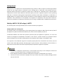
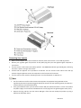
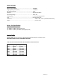
ATD‐5950 200 WATT INVERTER •
•
•
•
•
•
•
•
•
•
•
•
For use with 12V systems Input DC voltage range: DC 10V‐15V Overload and short‐circuit protection Built‐in cooling fan (2) 110V AC 3‐prong grounded receptacles and overload indicator Modified sine wave (1) replaceable 20 Amp fuse Cigarette lighter plug‐in cable included 14 AWG 24" cigarette plug cable (black/red) with battery clamp Maximum Continuous Power: 200W Peak Load Power Rate: Up to 400W No Load Current Draw: Up to 0.3 Amps REV 03‐13 Welcome This ATD product has been carefully engineered and manufactured to give you dependable operation. Please read this manual thoroughly before operating your new ATD product, as it contains the information you need to become familiar with its features and obtain the performance that will bring you continued enjoyment for many years. Please keep this manual on file for future reference. About ATD Inverters ATD, an innovator in portable inverter design, has developed a new line of super‐efficient power inverters with the highest surge capability in the industry. These extremely advanced, microprocessor controlled units run cooler and more reliable than any in their class. Their superior surge capability allows them to start even the most difficult loads, including color televisions, TV/VCR combinations, microwaves, refrigeration units, even small air conditioners! They also have the highest efficiency available (up to 90%) which translates into longer running time and extended battery life. Inverters convert low voltage, direct current (DC) to 110‐volt alternating current (AC). Depending on the model and its rated capacity, the inverters draw power either from standard 12 volt automobile and marine batteries or from portable high power 12 volt sources. General Safety Warnings WARNING: The instructions and warnings contained in this manual should be read and understood before using or operating this unit. Do not allow anyone to use or operate this unit until they have read this manual and have developed a thorough understanding of how this unit works. Failure to observe any of the following instructions could result in severe personal injury to unit user and bystanders, or cause damage to the unit and property. Keep this manual for future reference. Note: The warnings and cautions discussed in this instruction manual cannot cover all possible conditions and situations that may occur. It must be understood by the operator that common sense and caution are factors which cannot be built into this product, but must be supplied by the operator. WARNING: Do not operate, setup or plug in this tool if you are tired or under the influence of alcohol, drugs, or medications that could affect your ability to use the tool properly. WARNING: Dress properly. Do not wear loose clothing or jewelery as they can be caught in moving parts. Wear restrictive hair covering to contain long hair. WARNING: Do not reach over or across running machines. Keep proper footing and balance at all times. Non‐skid footwear is recommended when working.
REV 03‐13 Lead Acid Battery Safety Warnings CA Prop 65 WARNING: Batteries contain lead and other chemicals known to the State of California to cause cancer, birth defects and other reproductive harm. Wash hands after handling. WARNING: WORKING AROUND LEAD‐ACID BATTERIES MAY BE DANGEROUS. •
•
•
•
Lead‐acid batteries release explosive gases during normal operation, charging and jump starting. All lead‐acid batteries (car, truck and boat) produce hydrogen gas which may violently explode in the presence of fire or sparks. Do not smoke, use matches or a cigarette lighter while near batteries. Only work with lead‐acid batteries in a well‐ventilated area. Do not handle the battery while wearing vinyl clothing because static electricity sparks are generated when vinyl clothing is rubbed. To reduce risk of battery explosion, follow these instructions and those published by the battery manufacturer and manufacturer of any equipment you intend to use in the vicinity of the battery. Review cautionary markings on these products and on engine. EYE PROTECTION: • User and bystanders should always wear eye protection, appropriate protective clothing and other safety equipment when working near lead‐acid batteries. Do not touch eyes while working on or around lead‐
acid batteries. • IF SPLASHED WITH BATTERY ACID, IMMEDIATELY FLUSH AFFECTED AREA SUCH AS FACE AND PARTICULARLY THE EYES WITH CLEAN WATER. SEEK MEDICAL ATTENTION AND CONTINUE FLUSHING FACE AND EYES UNTIL MEDICAL HELP ARRIVES. WORKING IN ENGINE COMPARTMENT: • Use extreme caution while working within the engine compartment, because moving parts may cause severe injury. Read and follow all safety instructions published in the vehicle’s Owner’s Manual. GENERAL PRECAUTIONS / PERSONAL PRECAUTIONS: • Never work alone with lead‐acid batteries. Make sure that someone is around to give assistance if you need help. • Wear complete eye protection and clothing protection. Avoid touching eyes while working near battery. • In case of battery acid contact with eyes, skin or clothing, always have soap and water near your work area. • Remove jewelery such as rings, bracelets, necklaces and watches when working around a battery. A lead‐acid battery can produce a short circuit current, which can melt metals and result in a severe burn. • Do not drop tools or other metal objects on or near the battery as a spark may result, igniting explosive gases. • Never jump start or attempt to recharge a frozen battery. REV 03‐13 Electrical Safety Warnings WARNING: Read all safety warnings and instructions. Failure to follow all warnings and instructions may result in electric shock, fire and/or serious injury or death. WARNING: Before connecting a tool to a power supply, always check to ensure the power supply corresponds to the voltage on the nameplate of the tool. A power supply with a voltage greater than that specified for the tool can result in serious injury to the user, as well as damage to the tool. Using a power supply with a voltage less than the nameplate rating is harmful to the motor. If in doubt, do not plug in the tool. WARNING: Grounded tools must be plugged into an outlet properly installed and grounded in accordance with all codes and ordinances. This tool is equipped with a 3‐prong plug and a 3‐wire grounding system. Never remove the grounding prong or modify the plug in any way. Do not use any adapter plugs. Check with a qualified electrician if you are in doubt as to whether the outlet is properly grounded. NOTE: Double insulated tools are equipped with a polarized plug (one blade is wider than the other). This plug will fit in a polarized outlet only one way. If the plug does not fit fully in the outlet, reverse the plug. If it still doesn’t fit, contact a qualified electrician to install a polarized outlet. Do not change the plug in any way. WARNING: To reduce the risk of electric shock, DO NOT use in damp conditions, on wet surfaces, or expose to rain. Do not plug in this tool or operate it with wet hands or while standing in water. WARNING: Never use the cord for carrying, pulling or unplugging the power tool. Grasp plug and pull to disconnect from outlet. Keep cord away from heat, oil, sharp edges or moving parts. Replace damaged cords immediately. WARNING: Do not carry the power tool with your finger on the switch. Ensure the switch is in the off position before plugging the tool into the power outlet. In the event of a power failure while a tool is being used, turn the switch off to prevent surprise starting when the power is restored. WARNING: Always remove the power cord from the electric outlet when making adjustments, changing parts, cleaning or working on the tool. WARNING: Care should be taken to arrange the cord so it will not be stepped on, tripped over, or otherwise subjected to damage or stress. WARNING: Never attempt to plug in or operate equipment with defective or damaged wires, power cord or power cord plug. Have any defective or damaged parts replaced immediately by qualified personnel. WARNING: Avoid body contact with electrically grounded surfaces. There is an increased risk of electric shock if your body is grounded. REV 03‐13 Electrical Safety Warnings (Continued) WARNING: If the work area is not equipped with a permanently installed Ground Fault Circuit Interrupter outlet (GFCI), use a plug‐in GFCI between the power tool or extension cord and the power receptacle. WARNING: If an extension cord is necessary, use only ‘Listed’ extension cords. If used outdoors, they must be marked “For Outdoor Use”. Those cords having a 3‐prong grounding type plugs and mating receptacles are to be used with grounded tools. WARNING: Use of improper size or gauge of extension cord may cause unsafe or inefficient operation of your tool, or cause damage to your tool. Be sure your extension cord is rated to allow sufficient current flow to the motor. If in doubt, always use a larger gauge cord. Be sure to check the voltage requirements of the tool to your incoming power source. NOTE: The table below shows the correct size to use according to cord length and the amperage draw of the tool (specified on the nameplate). When in doubt, use the next heavier gauge. The smaller the gauge number, the heavier the cord. (AWG = American Wire Gauge). Minimum Gauge for Extension Cords (AWG) (when using 120 volts only) Ampere Rating Total Length of Cord in Feet (meters) More Than Not More Than 25' (7.6m) 50' (15m) 100' (30.4m) 150' (45.7m) 0 6 18 16 16 14 6 10 18 16 14 12 10 12 16 16 14 12 12 16 14 12 Not Recommended Inverter Safety Warnings WARNING: Read all the Cautions and Warnings before installing and using the power inverter. The inverter must be properly installed. If you are not familiar with 12 volt high current wiring, it is recommended that you have a professional automotive installer install the inverter. Failure to follow all warnings and instructions may result in electric shock, fire and/or serious injury or death.
WARNING:
The power inverter generates 115 VAC power from your 12 volt car battery. Treat the 115 VAC output just like you treat the 115 VAC in your house. Keep children away from the unit. WARNING: ATD Tools, Inc. does not authorize or recommend this inverter or any related products to be used with life support devices or systems. REV 03‐13 Inverter Safety Warnings (Continued) WARNING: Handling the cord on this product or cords associated with accessories sold with this product, may expose you to lead, a chemical known to the State of California to cause cancer and birth defects or other reproductive harm. Wash hands after handling. WARNING: With use, the inverter will become warm and possibly hot. Keep it away from any heat sensitive materials. Make sure the inverter is not close to any potential source of flammable fumes, gases or clothing. Keep the unit away from flammable material or in any location which may accumulate flammable fumes or gases, such as the battery compartment of your car, boat, RV or truck. WARNING: Do not operate the unit in an enclosed area that contains automotive type lead‐acid batteries. This type of battery emits explosive hydrogen gas that can be ignited by sparks. WARNING: Do not use the inverter near an open engine compartment. WARNING: Keep the inverter dry. DO NOT allow the inverter to come into contact with rain or moisture. DO NOT operate the inverter if you, the inverter, the device being operated or any other surfaces that may come in contact with any power source are wet. Water and many other liquids can conduct electricity, which may lead to serious injury. WARNING: Do not connect the unit to AC distribution wiring. WARNING: Only connect the power inverter to a 12‐volt battery accessory outlet or 12‐volt battery. Make sure the AC plug connection is tight. Do not modify the AC receptacle in any way. WARNING: Do not place the inverter in direct sunlight. Keep the unit in cool environments. The ideal air temperature for operation is between 50° and 80°F. Keep out of direct sunlight and away from heating vents, radiators or other sources of heat. Keep the inverter well ventilated in order to properly disperse heat generated while it is in use. Make sure there are several inches of clearance around the top and sides and do not block the slots of the inverter. WARNING: Do not open the unit. High voltages are present inside. WARNING: Use proper size wiring. High power inverters can draw many amps from the 12 volt source and can melt wires if not fused and sized properly. WARNING: Some chargers for small nickel‐cadmium batteries can be damaged if connected to the unit. Do not use the unit on small battery‐operated appliances such as flashlights, razors and night lights that can be plugged directly into an AC outlet to recharge. Also do not use the unit on certain battery chargers for battery packs used in hand power tools. These chargers will have a warning label indicating that dangerous voltages are present at the battery terminals. WARNING: This device does not include an internal Ground Fault Circuit Interrupter (GFCI).
REV 03‐13 Getting Started When you turn on an appliance or a tool that operates using a motor or tubes, it requires an initial surge of power to start up. This surge of power is referred to as the "starting load" or "peak load". Once started, the tool or appliance requires less power to continue to operate. This is referred to as "continuous load" in terms of power requirements. You will need to determine how much power your tool or appliance requires to start up (starting load) and it's continued running power requirements (continuous load). Power consumption is rated either in wattage (watts) or in amperes (amps) and this information is usually stamped or printed on most appliances and equipment. If this information is not indicated on the appliance or equipment, check the owner's manual or contact the manufacturer to determine if the device you are using is compatible with a modified sine wave source. Multiply: AMPS X 110 (AC voltage) = WATTS This formula yields a close approximation of the continuous load of your Appliance Multiply: WATTS X 2 = Starting Load This formula yields a close approximation of the starting load of your appliance. Most often the start up load of the appliance or power tool determines whether your inverter has the capability to power it. To determine whether the inverter will operate a particular piece of equipment or appliance, run a test. The inverters are designed to automatically shut down in the event of a power overload. This protection feature prevents damage to the unit while testing appliances and equipment with ratings in the 200 watt range. If an appliance in the 200 watt range will not operate properly when first connected to the inverter, turn the inverter rocker switch ON (I), OFF(O), and ON (I) again in quick succession. If this procedure is not successful, it is likely that the inverter does not have the required capacity to operate the appliance in question. Important •
•
•
The inverter is designed to operate from a 12‐volt power source only. Do not attempt to connect the inverter to any other power source, including any AC power source. Do not attempt to extend or otherwise modify the 12‐volt power cord attached to your inverter. 110 volts of current can be lethal. Improper use of your inverter may result in property damage, personal injury or loss of life. REV 03‐13 Connecting Your Inverter 1.
2.
3.
4.
5.
Make sure the ON/OFF rocker switch located on the front panel of the inverter is in the OFF (0) position. Remove your cigarette lighter and push the 12 volt power plug firmly into the cigarette lighter receptacle in your vehicle. Turn the inverter rocker switch to the ON (I) position. The GREEN LED Indicator light should glow, confirming that there is power running to the inverter. Confirm that the appliance to be operated is turned OFF. Turn the inverter rocker switch to the OFF (0) position. Plug the appliance into the AC receptacle on the front panel of the inverter. Turn the inverter rocker switch to the ON (I) position. Turn the equipment or appliance on. Note •
•
•
Use of an extension cord from the inverter to the appliance or equipment being operated will not significantly decrease the power being generated by the inverter. For best operating results, the extension cord should be no more than 50 feet long. If the green LED blinks when you first turn the inverter ON, this indicates that there is a short circuit within the power supply. Turn the inverter OFF. Remove the 12 volt plug from the cigarette lighter socket, firmly Reinsert the plug, and then turn the inverter ON again. If this does not remedy the problem try using a different 12 volt power source. REV 03‐13 Television and Audio Suggestions Although these inverters are shielded and filtered to minimize signal interference, some interference with your television picture may be unavoidable, especially with weak signals. However, here are some suggestions that may improve reception. 1. First, make sure that television antenna produces a clear signal under normal operating conditions (i.e., at home plugged into a standard 110V AC wall outlet). Also, ensure that the antenna cable is properly shielded and of good quality. 2. Change the positions of the inverter, antenna cables and television power cord. 3. Isolate the television, its power cord and antenna cables from the 12‐volt power source by running an extension cord from the inverter to the television set. 4. Coil the television power cord and the input cables running from the 12‐volt power source to the inverter. 5. Attach a "Ferrite Data Line Filter" to the television power cord. More than one filter may be required. These filters are available at most electronic supply stores. Note •
Inexpensive sound systems may emit a "buzzing" sound when operated with the inverter. This is due to inadequate filters in the sound system. There is no solution to this problem short of purchasing a sound system with a higher quality power supply. Blown Automotive Fuses Depending on the make and model of your automobile, running the power inverter near full capacity from your cigarette lighter port may result in a blown automotive cigarette lighter fuse. This fuse will need to be replaced with the same size fuse. Please note, a blown automotive fuse will not cause damage to your car wiring. To avoid blowing an automotive fuse in this situation, do not operate the power inverter over 200 watts for extended periods of time from your cigarette lighter or 12 volt power port. Blown Power Inverter Fuses Your power inverter is equipped with a 20‐amp spade type fuse. With reasonable care it should not be necessary to replace these fuses. Most blown fuses are the result of reverse polarity or a short circuit within the appliance or equipment being operated. If the fuse happens to blow, disconnect the appliance or equipment immediately, find the source of the problem, repair it, and then install a new fuse. Source of Power Most automobile and marine batteries will provide an ample power supply to the inverter for 30 to 60 minutes even when the engine is off. Actual time may vary depending upon the age and condition of the battery, and the power demand being placed on it by the equipment being operated with the inverter. If you decide to use the inverter while the engine is off, we recommend that you start the engine every hour and let it run for approximately 10 minutes to recharge the battery. We also recommend that the device plugged into the inverter be turned OFF before starting the vehicle engine. Although it is not necessary to disconnect the inverter when turning over the engine, it may momentarily cease to operate as the battery voltage decreases. When the inverter is not supplying power, it draws very low amperage from the battery and may be left connected to the battery for up to three hours. However, we recommend the inverter always be disconnected when not in use. REV 03‐13 Inverter Protection Features The RED LED Indicator light will turn on and the inverter will turn itself off automatically when: 1. The power input from the battery drops to 9.5 volts.(When the power input drops to 10.5 volts, an alarm will sound for an extended period). 2. The power input from the battery exceeds 15.5 volts. 3. The continuous draw of the equipment or appliance being operated exceeds 200 watts. 4. The surge draw of the equipment or appliance being operated exceeds 400 watts. 5. The circuit temperature exceeds 165°F. Note •
•
The inverter is equipped with a cooling fan which is designed to run continuously while the inverter is operating. Automatic shut down caused by high circuit temperatures will occur when the cooling fan is unable to maintain a cool enough temperature for safe operation of the inverter. In the event of automatic shut down or continuous audible alarm, turn the inverter rocker switch to the OFF (0) position until the source of the problem has been determined and resolved. How Power Inverters Work There are two stages in which a power inverter changes the 12‐volt DC (or battery) power into 110V AC (household current). STAGE 1: The inverter uses a DC‐to‐DC converter to increase the DC input voltage from the power source to 145 volts DC. STAGE 2: The inverter then converts the high voltage DC into 110V AC (household current), using advanced MOSFET (Metal‐
oxide‐Semiconductor Field Effect Transistor) transistors in a full bridge configuration. This design provides all our inverters with the capability to start and run difficult reactive loads, while providing excellent overload capability. The waveform that is generated by this conversion is a "modified sine wave" as shown in the diagram below. The modified sine wave produced by our inverters has a root mean square (RMS) voltage of 110 volts. The majority of AC voltmeters are calibrated for RMS voltage and assume that the measured waveform will be a pure sine wave. Consequently, these meters will not read the RMS modified sine wave voltage correctly and, when measuring the inverter output, the meters will read about 20 to 30 volts too low. To accurately measure of the output voltage of the inverter, use a true RMS reading voltmeter such as a Fluke 87 Fluke 8060A Beckman 4410, Triplet 4200 or any multimeter identified as "True RMS" REV 03‐13 In Review •
•
•
•
•
•
•
•
•
•
•
•
•
Never attempt to operate the inverter from any power source other than a 12‐volt DC volt battery. The inverter is designed to be connected to the power source with the 12 volt power plug. Do not attempt to modify the power cord or plug. While connecting the inverter to the power source, make certain that the inverter is positioned far away from any potential source of flammable fumes or gases, Make certain the power consumption of the appliance or equipment you wish to operate is compatible with the capacity of the inverter. Do not exceed 200 watts. When attempting to operate battery chargers, monitor the temperature of the battery charger for approximately 10 minutes. If the battery charger becomes abnormally warm, disconnect it from the inverter immediately. Use only 20 amp spade type fuses. When operating the inverter with an automobile or marine battery, start the engine every 30 to 60 minutes and let it run for approximately 10 minutes to recharge the battery. In the event of a continuous audible alarm or automatic shut down, turn the inverter OFF immediately. Do not restart the inverter until the source of the problem has been identified and corrected. To avoid battery drain, always disconnect the inverter when not in use. Do not expose the inverter to rain or moisture. Avoid placing the inverter near sources of heat or in direct sunlight. While in use, make sure the inverter is properly ventilated. Do not operate the inverter near flammable materials, fumes or gases. TROUBLESHOOTING: PROBLEM: Low or No Output Voltage ? Reason: Poor contact with lighter socket or battery clamps 9 Solution: Unplug and reinsert 12 volt plug or reattach battery clamps. ? Reason: Using incorrect type of voltmeter to test output voltage. 9 Solution: Use true RMS reading meter. PROBLEM: Red LED Indicator On _____ ? Reason: Battery voltage below 9.5 volts. 9 Solution: Recharge or replace battery. _____ ? Reason: Equipment being operated draws too much power. 9 Solution: Use a higher capacity inverter or do not use this equipment. REV 03‐13 PROBLEM: Red LED Indicator On (Continued) _____ ? Reason: Inverter is too hot (thermal shut down mode). 9 Solution: Allow inverter to cool. Check for adequate ventilation. Reduce the load on the inverter to rated continuous power output. _____ ? Reason: Unit may be defective. 9 Solution: See Warranty and call customer service. PROBLEM: TV Interference ? Reason: Electrical interference from the inverter. 9 Solution: Add a ferrite data line filter on to the TV power cord. Refer to TV & Audio section of this manual. PROBLEM: Low Battery Alarm On All The Time ? Reason: Input voltage below 10.5 volts. 9 Solution: Keep input voltage above 10.5 volts to maintain regulation. ? Reason: Poor or weak battery. 9 Solution: Recharge or Replace battery. ? Reason: Inadequate power being delivered to the inverter or excessive voltage drop 9 Solution: Check condition of cigarette lighter socket. Clean or replace if necessary, or check cable clamp connections. PROBLEM: TV Does Not Work ? Reason: TV does not turn on. 9 Solution: Try turning the inverter ON/OFF/ON. Contact TV manufacturer for startup surge specifications and/or to see if the TV is compatible with a modified sine wave. A larger inverter may be required. REV 03‐13 SPECIFICATIONS Max. Continuous Power...............................................................200 Watts Surge Capability (Peak Power) .....................................................400 Watts No Load Current Draw .................................................................0.3A Waveform ...................................................................................Modified Sine Wave Input Voltage Range ....................................................................DC11‐15V AC Receptacles ...........................................................................110V AC 3 prong grounded Fuse ...........................................................................................20 amp (spade type) Dimensions …………………………………………………………………………………….4.88” x 4.96” x 2.05” (124mmx126mmx52mm) Weight…………………………………………………….………...….……...................1.6Ib (0.75 kg) Power Cord Specification 1pc 18AWG x 2c (Black) with cigarette plug 1pc 14AWG x 2c (Black) with Battery Clamp (Black, Red) Inverter Cables 200W & 400W Inverters come with a cigarette lighter plug/cable & clamp on battery cables. 800W OR GREATER MUST BE HARD WIRED TO BATTERY. *USE THE THICKEST WIRE AVAILABLE IN THE SHORTEST LENGTH PRACTICAL Wattage
0'-4' Length
5'-10' Length
800W
#2 AWG
#0 AWG
1000W
#0 AWG
#2/0 AWG
1500W
#0 AWG
#2/0 AWG
2000W
#2/0 AWG
#4/0 AWG
3000W
#2/0 AWG
#4/0 AWG
6000W
#2/0 AWG
#4/0 AWG
REV 03‐13 WARRANTY 1 YEAR REPLACEMENT WARRANTY THIS WARRANTY AND CONFIRMED RECEIPT (S) SHOULD BE RETAINED BY THE CUSTOMER AT ALL TIMES The warranty is only made available by returning the product to the point of sale. PURCHASED FROM:________________________________________________ DATE PURCHASED: ________________________________________________ INVOICE/RECIEPT NUMBER:_________________________________________ Your ATD‐5950 is warranted for a period of 12 months from the original date of. Any consumable items, such as carbon brushes, batteries, drill and driver bits and chucks are covered by a 90 day warranty. This warranty is valid for defects in workmanship or materials only, and is handled at the point of sale. The warranty given on this tool is against defects in workmanship and materials only. Any misuse, abuse or accidental damage is not covered by warranty. The following actions will also result in the warranty being void: • If the tool has been operated on a supply voltage other than that specified on the tool. • If the tool shows signs of damage or defects caused by or resulting from abuse, accidents or alterations. • If the tool is disassembled or tampered with in any way. Note: Warranty excludes consumable parts such as carbon brushes, batteries, drill and driver bits and chucks. [Affix receipt or invoice here for safe keeping]
REV 03‐13