1
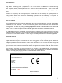
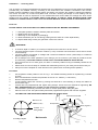
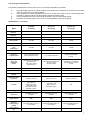
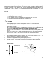
Contents
Page
1
Important information.
2
Introduction.
3
In-Ceiling and In-Wall features, plus declaration of conformity.
4
In-Ceiling installation.
5
Fine tuning of In-Ceiling speakers and technical specification.
6
In-Wall installation.
7
Fine tuning of In-Wall speakers and dB adjustments of Gold and Silver In-Ceiling and In-Wall
loudspeakers.
8
In-Wall technical specifications.
9
Guarantee Statement.
10 -11
Multi-lingual safety warnings- German, Italian, Spanish and French.
IMPORTANT INFORMATION
The CP Series In-Ceiling and In-Wall loudspeakers will provide long term satisfaction in terms of
sound quality and reliability provided they are installed correctly, according to the instructio ns and
conditions contained in this manual. Please read this installation guide carefully before proceeding. We
assume the installer is trained and skilled in the correct and safe use of hand and power tools and has a
working knowledge of local building and fire regulations/codes as well as experience of the
conditions/services behind walls and ceilings into which these speakers will be installed. IF IN DOUBT
ABOUT YOUR ABILITY TO INSTALL THESE PRODUCTS SAFELY AND CORRECTLY PLEASE CONTACT YOUR
LOCAL AUTHORISED MONITOR AUDIO DEALER OR CUSTOM INSTALLER.
WARNINGS:
•
•
•
•
•
•
•
A minimum depth of 190mm (7½ Inches) is required for the In-Ceiling back box to fit into recess. The
In-Wall requires 98mm (4 Inches)
The fixing clamps require a minimum of 25mm (1 Inch) of surface area around the cut-out hole to ensure
a secure fixing!
The fixing clamps will operate on ceilings or walls with a minimum thickness of 9mm (3/8 Inches) to a
maximum depth of 32mm (1¼Inches)
Do not attempt to fix these speakers to your ceiling or wall if you are unsure of your ability to provide a
secure and safe fixing. IF IN DOUBT CONTACT YOUR LOCAL AUTHORISED MONITOR AUDIO
DEALER OR CUSTOM INSTALLER.
Ensure that there are no water pipes, air ducts or electricity cables running immediately behind the cut
out area!
Please work from secure steps or scaffold and avoid trailing wires for your safety and those around you.
Always turn off the amplifier or other devices in the system when connecting these speakers
www.monitoraudio.co.uk
1
Introduction
Congratulations and thank you for purchasing this high performance Monitor Audio CP Series loudspeaker.
This is no ordinary architectural speaker. Monitor Audio has taken great care to apply its award-winning
loudspeaker technologies to create a hi-fidelity design, which promises exceptional sound quality and reliability.
CP stands for ‘Controlled Performance’. Each CP In-Ceiling or In-Wall product is fitted with its own rigid
enclosure to make sure the sound is always the same, wherever it is fitted.
For all In-Ceiling and I n-Wall applications, you can rely on the elevated standards of build quality and
performance that have earned Monitor Audio’s Bronze, Silver and Gold loudspeaker ranges acclaim from
professionals around the world.
In designing the Bronze, Silver and Gold CP In-Ceiling and In-Wall speakers, Monitor Audio offers three levels of
performance for a wide range of applications and budgets, but promises market-leading reliability and value in
each case.
Speaker Location
We strongly recommend that these speakers be installed professionally so that positioning and fine-tuning can be
successfully undertaken using sound measuring equipment, coupled with room layout experience and technical
knowledge.
Your CP series In-Ceiling and In-Wall loudspeakers installed in your home theatre can be used as surround
speakers in conjunction with freestanding speakers. If you are unsure about where to locate your surround
speakers for optimum performance, please contact your Monitor Audio Dealer for advice.
When mounting your speakers in the ceiling, locate the speakers 0.6-2m (2 to 6 feet) behind your listening
position. The speakers should be installed 2 to 3m (6 to 10 feet) apart centre to centre.
A Typical example is Shown below.
Fine tuning & Calibration
Surround
Sound
Room Plan
View
Typical In-Ceiling
Your amplifier or A/V receiver
manual will contain information
and detailed instruction on fine
tuning/calibrating your system
so that the correct balance is
achieved between the various
speakers. It may be necessary
to adjust the CP speakers as
described in pages 4 and 6
Typical In-Wall
2
Gold CP Features
®
Gold CP In-Ceiling speakers utilise our C-CAM (Ceramic Coated Aluminium Magnesium alloy) cone, featuring
®
Rigid Surface Technology (RST ). Impressions on the cone’s surface are designed to eliminate bending,
increase stiffness and lower mass when compared with conventional cone driver designs. The result is a much
faster response, offering music reproduction that is closer to the original performance. A rigid die-cast metal
chassis design features a vented rear section and provides extremely low distortion with typically higher output
levels.
Additional high frequency and mid-range frequency controls allow the user to set-up the system precisely to
obtain optimum performance within the listening environment. This inherent flexibility makes the Gold CP InCeiling speaker suitable for a wider range of demanding applications than that offered by its competitors. It
promises a truly ‘high-end’ performance from a custom fit, discreetly installed speaker system.
Silver CP Features
®
Our C-CAM (Ceramic Coated Aluminium Magnesium alloy) cone profiles and rubber surrounds maximise the
potential of the driver mechanism. The new surrounds allow greater cone excursions with lower distortion and
improved frequency response linearity. The flush cone edge provides a very smooth response and a natural,
accurate sound. The Silver CP pivoting (In-Ceiling only) tweeter is based on Monitor Audio’s famous 25mm gold
®
C-CAM dome. Improvements to the surround and motor system have extended the frequency response to
30kHz, so that it is ready to exploit new wide bandwidth digital audio formats such as SACD and DVD-A.
An additional high frequency control offers a fine-tuning option to allow the user to set -up the system precisely
and obtain optimum performance within the listening environment. This additional flexibility makes the Silver CP
In-Ceiling and In-Wall speakers suitable for a wider range of demanding residential and commercial applications.
Bronze CP Features
®
The Bronze drive unit, (MMP Mk2) offers an advanced driver technology developed from Monitor Audio’s
original Metal Matrix Polymer cone material and uses a high-pressure injection moulding process to achieve
®
different thickness at critical points in the cone geometry. MMP Mk2 provides better stiffness and consistency
and tighter production tolerances resulting in superior sonic performance. The new bass-mid chassis design has
a vented rear section that reduces thermal power compression to deliver increased dynamic range and higher
sound pressure levels. This venting also lowers distortion by balancing the pressure within the voice-coil motor
system. It means clean, crisp bass and an even clearer mid-range performance.
®
High frequency performance has been improved by the evolution of the C-CAM tweeter. The new tweeter
utilises a pivoting action (In-Ceiling only) to provide optimum imaging and flexible set-up options. The bespoke
crossover uses high-grade polypropylene film capacitors, and low distortion inductors
Declaration of Conformity
We, Monitor Audio Ltd.
24 Brook Road
Rayleigh
Essex
SS6 7XL
England
Declare in own responsibility, that the products described in this manual are in
compliance with technical standards:
EN 50082-1 : 1998
EN 55013 : 2001
EN 50020 : 2002
Dean Hartley (Technical Director)
Monitor Audio Ltd
England
3
Installation – In-Ceiling Units
The CP Series In-Ceiling loudspeakers will provide long term satisfaction in terms of sound quality and reliability
provided they are installed correctly, according to the instructions and conditions contained in this manual.
Please read this installation guide carefully before proceeding. We assume the installer is trained and skilled in
the correct and safe use of hand and power tools, and has a working knowledge of local building and fire
regulations/codes as well as experience of the conditions/services behind walls and ceilings into which these
speakers will be installed. IF IN DOUBT ABOUT YOUR ABILITY TO INSTALL THESE PRODUCTS SAFELY AND
CORRECTLY PLEASE CONTACT YOUR LOCAL AUTHORISED MONITOR AUDIO DEALER OR CUSTOM INSTALLER.
Parts List
PLEASE CHECK YOU HAVE THE FOLLOWING ITEMS IN THIS KIT BEFORE PROCEEDING:
•
•
•
•
•
1 x Complete speaker & tweeter assembly fitted to back box.
1 x Grille (which can be painted).
1 x Mounting cut out template (in packaging).
2 x Grille membrane (one for use during painting and the other as a clean replacement).
2 x Spare baffle fixing screws plus guarantee card in this manual.
WARNINGS:
•
•
•
•
•
•
•
A minimum depth of 190mm (7½ Inches) is required for the back box to fit into recess.
The fixing clamps require a minimum of 25mm (1 Inch) of surface area around the cutout hole to ensure
a secure fixing!
The fixing clamps will operate on ceilings with a minimum thickness of 9mm (3/8 Inches) to a maximum
depth of 32mm (1¼ Inches).
Do not attempt to fix these speakers to your ceiling if you are unsure of your ability to provide a secure
and safe fixing. IF IN DOUBT CONTACT YO UR LOCAL AUTHORISED MONITOR AUDIO DEALER.
Ensure that there are no water pipes, air ducts or electricity cables running immediately behind the cut
out area!
Please work from secure steps or scaffold and avoid trailing wires for your safety and those around you.
Always turn off the amplifier or other devices in the system when connecting these speakers.
Procedure
1.
6.
7.
Use template to locate position of cut out. Fig 1. The adhesive backing allows for repositioning a number
of times.
Draw round diameter to define the perimeter of the cut out - 250mm ( 9 7/8 inches )
Remove template and cut hole.
Locate speaker cable and connect by pushing the terminals in and releasing to clamp the cables as
shown below Fig 2.
Fit back box into prepared hole and tighten fixing clamps. These will move outwards on tightening! DO
NOT OVERTIGHTEN! Once contact is made 2-3 turns are all that is required.
Fit front Baffle if previously removed and check for sound quality before fitting the grille.
Paint at a time to suit. Use paint masks (membrane) supplied and replace with new item supplied.
8
TO FINE-TUNE THE SPEAKERS PLEASE REFER TO PAGE 4 AND 6.
2.
3.
4.
5.
Push down to fit cable
Hole to be cut
250mm ( 9 7/8”)
Red (Positive)
Black (Negative)
Position of 4
fixing clamps
In-Ceiling Template
Fig 1
Not to scale
Fig 2
4
Fine-tuning the loudspeakers
The following adjustments can be made to your CP in-ceiling loudspeakers as follows:
1.
2.
3.
4.
Pivoting tweeters (all CP In-Ceiling models) can be tilted up to 18 degrees in all directions to provide
optimum coverage if the following applies:
If the speakers are widely separated such that the music fails to blend into a central image when
operated in stereo mode then tilt the tweeter towards the listening area.
If the Soundstage seems too confined tilt the tweeter away from the listening area.
For further fine-tuning options of your CP In-Ceiling speakers please go to page 6.
Specifications - In-Ceiling
Gold CP
In-Ceiling
Silver CP
In-Ceiling
Bronze CP
In-Ceiling
55Hz – 30KHz
60Hz – 30KHz
62Hz – 22 KHz
8 Ohms
8 Ohms
8 Ohms
89dB
89dB
88dB
Maximum SPL
106.5 dBA
105.8 dBA
105 dBA
Power handling
120W
100W
80W
Recommended
Amp
requirements
30-120W
30-100W
20-80W
Bass alignment
Sealed enclosure
Sealed enclosure
Sealed enclosure
Drive unit
complement bass
1x 6.5” C-CAM bass driver
featuring RST technology
1x 6” C-CAM bass driver
1x 6.5” MMP2 second
generation Metal Matrix
Polymer
Drive unit
complement
tweeter
Pivoting 25mm C- CAM gold
alloy dome with
high power ceramic
magnet system
Pivoting 25mm C- CAM gold
alloy dome with
rare earth magnet
Pivoting 25mm C- CAM gold
alloy dome with rare earth
magnet
Overall diameter
281mm (11 1/16 inch)
281mm (11 1/16 inch)
281mm (11 1/16 inch)
Overall depth
181mm (7 1/8 inch)
181mm (7 1/8 inch)
181mm (7 1/8 inch)
Cut-out hole
diameter
250mm (9 7/8 inch)
250mm (9 7/8 inch)
250mm (9 7/8 inch)
Mounting depth
mm (inch)
175mm (6 7/8 inch)
175mm (6 7/8 inch)
175mm (6 7/8 inch)
Controls
+3db / 0dB / -3dB
High frequency
attenuation switch.
+3db / 0dB / -3dB
Mid-range frequency
attenuation switch.
+3db / 0dB / -3dB
High frequency
attenuation switch
N/A
Fixing type
4 position ‘dog’ type fixings
4 position ‘dog’ type fixings
4 position ‘dog’ type fixings
Connection
Gold plated ‘push’ type
terminals
Gold plated ‘push’ type
terminals
Gold plated ‘push’ type
terminals
Baffle material
MDF
MDF
MDF
Back box/
mounting flange
material
Mineral filled ABS plastic (UL
V1 fire rated)
Mineral filled ABS plastic (UL
V1 fire rated)
Mineral filled ABS plastic (UL
V1 fire rated)
Unit weight Kg
(lb)
3.0Kg (6.6Ib)
2.5Kg (5.5Ib)
2.4Kg (5.3lb)
Model
Frequency
response
Impedance
(nominal)
Sensitivity (1W@1M)
5
Installation - In-Wall Units
The CP Series In-Wall loudspeakers will provide long term satisfaction in terms of sound quality and reliability
provided they are installed correctly, according to the instructions and conditions contained in this manual.
Please read this installation guide carefully before proceeding. We assume the installer is trained and skilled in
the correct and safe use of hand and power tools, and has a working knowledge of local building and fire
regulations/codes as well as experience of the conditions/services behind walls and ceilings into which these
speakers will be installed. IF IN DOUBT ABOUT YOUR ABILITY TO INSTALL THESE PRODUCTS SAFELY AND
CORRECTLY PLEASE CONTACT YOUR LOCAL AUTHORISED MONITOR AUDIO DEALER OR CUSTOM INSTALLER.
Parts List
PLEASE CHECK YOU HAVE THE FOLLOWING ITEMS IN THIS KIT BEFORE PROCEEDING:
•
•
•
•
•
1
1
1
2
2
x
x
x
x
x
Complete speaker & tweeter assembly fitted to back box.
Grille (which can be painted).
Mounting cut out template (in packaging).
Grille membrane (one for use during painting and the other as a clean replacement).
Spare baffle mounting screws plus guarantee card in this manual.
WARNINGS:
•
•
•
•
•
•
•
A minimum depth of 98mm (4 Inches) is required for the back box to fit into wall/ceiling recess.
The fixing clamps require a minimum of 25mm (1 Inch) of surface area around the cut-out hole to ensure
a secure fixing!
The fixing clamps will operate on walls with a minimum thickness of 9mm (3/8 Inches) to a maximum
depth of 32mm (1¼ Inches).
Do not attempt to fix these speakers to your wall if you are unsure of your ability to provide a secure and
safe fixing. IF IN DOUBT CONTACT YOUR LOCAL AUTHORISED MONITOR AUDIO DEALER.
Ensure that there are no water pipes, air ducts or electricity cables running immediately behind the cut
out area!
Please work from secure steps or scaffold and avoid trailing wires for your safety and those around you.
Always turn off the amplifier or other devices in the system when connecting these speakers.
Procedure
1.
4.
Secure template in position. Please note that the outer profile indicates size of cut-out. Fig 3. The
adhesive backing allows for repositioning a number of times.
Cut hole and Locate speaker cable and connect as shown below Fig 4.
Fit back box into prepared hole and tighten fixing clamps. These will move outwards on tightening! DO
NOT OVERTIGHTEN! Once contact is made 2-3 turns are all that is required.
Paint at a time to suit. Use paint masks (membrane) supplied and replace with new item supplied.
5.
TO FINE-TUNE THE SPEAKERS PLEASE REFER TO PAGE 6.
2.
3.
Push down to fit cable
In-wall template
Hole size to be cut
387 x 234mm
(15 1/4” x 9 3/16” )
Position of 8
fixing clamps
Fig 3
Red (Positive)
Black (Negative)
Not to scale
Fig 4
6
Fine-tuning - In-Ceiling and In-wall speakers
The following adjustments can be made to your CP In-Ceiling and In-Wall loudspeakers as follows:
Adjusting H.F (High Frequency) control
(Silver CP and Gold CP models only)
The factory H.F setting provides a flat or 0dB level, which will suit the majority of typical installations.
However, it is possible to fine-tune the sound from the CP speakers to suit a room’s characteristics or
preferred listening tastes by using the following as a guide: a. Setting the switch in the +3dB position will add brightness and additional clarity to the system. This may
be effective in a room with a large amount of soft furnishings.
b. Setting the switch in the -3dB position will reduce the brightness on the system and provide a duller
sound. This may be effective in a room with a lack of soft furnishings, or in an installation with a wooden
floor.
Adjusting M.F (Mid-range Frequency) control
(Gold CP models only)
The factory M.F setting provides a flat or 0dB level, which will suit the majority of typical installations.
However, it is possible to fine-tune the sound from the Gold CP In-Ceiling and In-Wall speakers to suit a
room’s characteristics or preferred listening tastes by using the following as a guide: a. Setting the switch in the +3dB position will add presence and additional clarity to the system, particularly
in the vocal region. This may be effective for better resolution of dialogue and speech, or in an installation
where the listening position is a large distance from the speaker.
b. Setting the switch in the -3dB position will reduce the presence and the system will sound more ‘laid
back’. This may be effective where the speaker will be played for background music, or where the
listening position is situated close to the speaker.
7
Technical Specifications CP In-Wall
Model
Gold CP
In-Wall
Silver CP
In-Wall
Bronze CP
In-Wall
Frequency
response
55Hz – 30KHz
60Hz – 30KHz
62Hz – 22 KHz
Impedance
(nominal)
8 Ohms
8 Ohms
8 Ohms
Sensitivity
(1W@1M)
89dB
89dB
88dB
Maximum SPL
106.5 dBA
105.8 dBA
105 dBA
Power handling
120W
100W
80W
Recommended
Amp
requirements
30-120W
30-100W
20-80W
Bass alignment
Sealed enclosure
Sealed enclosure
Sealed enclosure
Drive unit
complement bass
1x 6.5” C-CAM bass driver
featuring RST technology
1x 6” C-CAM bass driver
1x 6.5” MMP2 second
generation Metal Matrix
Polymer
Drive unit
complement
tweeter
25mm C- CAM gold alloy
dome with high power
ceramic magnet system and
rear low resonance chamber
25mm C- CAM gold alloy
dome with rare earth magnet
25mm C- CAM gold alloy
dome with rare earth
magnet
Overall size
423mm high x 270 wide
(16 11/16 inches x 10 11/16
inches)
423mm high x 270 wide
(16 11/16 inches x 10 11/16
inches)
423mm high x 270 wide
(16 11/16 inches x 10 11/16
inches)
Overall depth
100mm (3 15/16 inches)
100mm (3 15/16 inches)
100mm (3 15/16 inches)
Cut-out hole size
387mm high x 234mm wide
(15 1/4 inches x 9 1/4
inches)
387mm high x 234mm wide
(15 1/4 inches x 9 1/4
inches)
387mm high x 234mm wide
(15 1/4 inches x 9 1/4
inches)
Mounting depth
95mm (3 3/4 inches)
95mm (3 3/4 inches)
95mm (3 3/4 inches)
Controls
+3db / 0dB / -3dB
High frequency attenuation
switch.
+3db / 0dB / -3dB
Mid-range frequency
attenuation switch.
+3db / 0dB / -3dB
High frequency attenuation
switch
Not Applicable
Fixing type
8 position ‘dog’ type fixings
8 position ‘dog’ type fixings
8 position ‘dog’ type fixings
Connection
Gold plated ‘push’ type
terminals
Gold plated ‘push’ type
terminals
Gold plated ‘push’ type
terminals
Baffle material
MDF
MDF
MDF
Back box/
mounting flange
material
Mineral filled ABS plastic (UL
V1 fire rated)
Mineral filled ABS plastic (UL
V1 fire rated)
Mineral filled ABS plastic (UL
V1 fire rated)
Unit weight Kg
(lb)
4.3Kg (9.5Ib)
3.0Kg (6.6Ib)
3.0Kg (6.6lb)
8
Guarantee and Service
The guarantee becomes valid upon completion of the attached guarantee card and its return within 30 days of
purchase.
This guarantee is void if the serial number has been removed or defaced.
This equipment has been fully tested prior to dispatch from the factory. Both the craftsmanship and the
performance of this product is guaranteed against manufacturing defects for the period of three years from the
date of purchase (see conditions below), provided that the product was supplied by an authorised Monitor Audio
retailer under the consumer sale agreement. (The words ‘consumer sale’ shall be construed in accordance with
section 15 of the supply of goods act 1973). Monitor Audio accepts no responsibility for defects arising from
accident, misuse, abuse, wear and tear, modification or operation outside of that specified within this instruction
manual. Neither will responsibility be accepted for damage or loss occurring during transit to or from the parties
claiming under this guarantee.
This guarantee covers both labour and parts. The liability of Monitor Audio is limited to the cost of repair or
replacement of the defective parts (at the discretion of Monitor Audio) and under no circumstances extends to
consequential losses or damage.
Claims under this Guarantee
The equipment should be returned in its packaging to the original supplier where possible, or to any other
authorised Monitor Audio dealer. If it is not possible to return the equipment by hand, then it should be sent
carriage prepaid via a reputable carrier. If the original packing is not available replacement packaging can be
purchased from Monitor Audio. If you have any difficulties complying with these requirements please contact us
at the following address:
Monitor Audio Ltd.
Unit 2, 24 Brook Road
Rayleigh
Essex
SS6 7XL
England
Tel:
44 (0) 1268 740580
Fax:
44 (0) 1268 740589
Internet: www.monitoraudio.co.uk
Email: [email protected]
This guarantee does not affect the statutory rights of the consumer under UK law and or relevant consumer laws
in other countries or states.
Monitor Audio reserve the right to alter specifications at any time without notice if it is considered that an
improvement can be made to the product.
9
Warnungshinweis
Die zum Wand/Decken-Einbau vorgesehenen Lautsprecher der CP Serie werden Ihnen auf lange Zeit mit ihrer vorzüglichen Tonqualität und
Zuverlässigkeit viel Freude bereiten, vorausgesetzt, dass sie vorschriftsmäßig nach den in diesem Handbuch angegebenen Anleitungen und
Bedingungen eingebaut werden. Lesen Sie bitte vor Beginn der Arbeiten diese Installationsanleitungen sorgfält ig, da wir voraussetzen, dass der
Installateur im vorschriftsmäßigen und sicheren Gebrauch von Elektrowerkzeugen unterwiesen und erfahren ist. Es wird ebenso vorausgesetzt, dass er
ausreichende Kenntnisse der örtlichen Bau und Brandschutzbestimmungen besitzt, sowie entsprechende Erfahrung des Unterputzzustandes und der
eventuell vorhandenen Leitungen in Wänden und Zimmerdecken besitzt, in welche diese Lautsprecher eingebaut werden sollen. SOLLTEN SIE
DARAN ZWEIFELN; DIESE ARBEITEN MIT SICHERHEIT- UND ORDNUNGSGEMÄSS AUSFÜHREN ZU KÖNNEN, WENDEN SIE
SICH BITTE AN IHREN AUDIO -VERTRAGSHÄNDLER.
WARNUNGSHINWEIS:
•
•
•
•
•
•
•
Es wird eine Mindesteinbautiefe von 190 mm (7.5 Zoll ) für den Deckeneinbau der Backbox benötigt. Für den Wandeinbau sind
98 mm (4 Zoll) vorzusehen.
Die Befestigungsklemmen benötigen eine Oberfläche von 25 mm (1 Zoll) um das ausgeschnittene Loch herum, um eine sichere
Befestigung zu gewähren!
Die Befestigungsklemmen können bei Decken oder Wänden mit einer Mindestdicke von 9 mm (0,35 I) bis zu einer Mindesttiefe
von 32 mm (1,25 Zoll) angewendet werden
Versuchen Sie nicht, diese Lautsprecher an Ihrer Wand oder Decke anzubringen, wenn Sie nicht voll überzeugt sind, dass Sie
imstande sind, diese vorschriftsmäßig und sicher zu montieren. IM ZWEIFELSFALLE WENDEN SIE SICH BITTE AN IHREN
ZUGELASSENEN ÖRTLICHEN AUDIOHÄNDLER.
Vergewissern Sie sich, dass sich keine Wasser- Luft- oder Elektroleitungen hinter dem Ausschnitt befinden!
Benutzen Sie bitte immer nur sichere Tritte oder Leitergerüste und vermeiden Sie im Interesse Ihrer Sicherheit sowie der aller
anwesenden Personen herabhängende und auf dem Boden schleifende Kabel und Leitungen.
Bei Anschluss dieser Lautsprecher müssen die Verstärker sowie alle weiteren Geräte im System ausgeschaltet sein.
Avvertimenti
La Serie CP di altoparlanti incassati nel soffitto e nelle pareti offrirà un ottimo funzionamento in termini di qualità Sonora ed affidabilità, purché gli
altoparlanti siano installati correttamente, seguendo le istruzioni e le condizioni contenute in questo manuale. Si prega di leggere attentamente questa
guida all’installazione prima di procedere, poiché presumiamo che l’installatore sia addestrato e sia in grado di utilizzare gli attrezzi manuali ed elettrici.
Ed abbia inoltre una conoscenza operativa dell’edificio locale e delle norme/codici antincendio e conosca le condizioni/i servizi dietro pareti e soffitti
nei quali saranno installati questi altoparlanti. IN CASO DI DUBBI SULLA PROPRIA ABILITÀ AD EFFETTUARE QUESTA
INSTALLAZIONE IN MODO CORRETTO E SICURO, SI PREGA DI CONTATTARE IL PROPRIO CONCESSIONARIO LOCALE
AUTORIZZATO ALLA VENDITA DI APPARECCHI AUDIO.
ATTENZIONE:
•
•
•
•
•
•
•
E’ necessaria una profondità minima di 190 mm perché la cassa posteriore possa essere installata nel vano del soffitto. Quella
da incassare nella parete necessita di uno spazio di 98 mm.
I dispositivi di fissaggio necessitano di una superficie minima di 25 mm intorno al foro intagliato per assicurare un fissaggio
sicuro!
I dispositivi di fissaggio saranno funzionali in soffitti e pareti che abbiano uno spessore di almeno 9 mm fino ad uno spessore
massimo di 32 mm.
Non si deve tentare di fissare questi altoparlanti in un soffitto o una parete se non si è certi della propria abilità di effettuare
un’installazione appropriata e sicura. IN CASO DI DUBBI CONTATTARE IL PROPRIO CONCESSIONARIO LOCALE
AUTORIZZATO ALLA VENDITA DI APPARECCHI AUDIO.
Accertarsi che non vi siano di tubi dell’acqua, condotti d’aria o cavi elettrici installati appena dietro l’area intagliata!
Lavorare su scale o impalcature sicure ed evitare di tirare dei fili per la propria sicurezza e quella di altre persone.
Spegnere sempre l’amplificatore o altri dispositivi dell’impianto quando si collegano questi altoparlanti.
10
Advertencias
La CP Series de altavoces de empotrado en el techo y en la pared ofrecerán una satisfacción a largo plazo en concepto de calidad del sonido y
fiabilidad, siempre y cuando se instalen correctamente, según las instrucciones y condiciones contenidas en este manual. Antes de proceder, lea
detenidamente esta guía de instalación en la que se supone que el instalador está capacitado y es hábil en el uso correcto y seguro de herramientas
manuales y eléctricas, y que tiene conocimientos prácticos de las regulaciones / códigos locales en materia de construcción e incendios, así como
experiencia en cuanto a las condiciones / servicios que se encuentran detrás de los techos y paredes en los que se instalarán estos altavoces. EN
CASO DE DUDA DE QUE SEA CAPAZ DE INSTALAR ESTOS DISPOSITIVOS DE UNA MANERA SEGURA Y CORRECTA,
SÍRVASE CONTACTAR CON SU DISTRIBUIDOR AUTORIZADO LOCAL DE AUDIO MONITORES
ADVERTENCIAS:
•
•
•
•
•
•
•
Se requiere una profundidad mínima de 190 mm (7,5 pulgadas) para que la caja de respaldo de empotrado en el techo
quepa en el rebaje. La de empotrado en la pared requiere de 98 mm (4 pulgadas)
¡Las grapas de fijación requieren un área de superficie de 25 mm (1 pulgada), como mínimo, alrededor del agujero perforado
para garantizar una fijación segura!
Las grapas de fijación servirán en techos o paredes con un espesor mínimo de 9 mm (0,35 pulgadas) hasta una profundidad
máxima de 32 mm (1,25 pulgadas)
No intente instalar estos altavoces en el techo o pared si no está seguro de que sea capaz de ofrecer una instalación
correcta y segura . EN CASO DE DUDA CONTACTE CON SU DISTRIBUIDOR AUTORIZADO LOCAL DE AUDIO
MONITORES.
¡Cerciórese de que no haya tuberías de agua, ductos de aire o cables eléctricos que pasen inmediatamente por detrás del
área perforada!
Para la instalación use por favor escaleras o andamiaje y evite dejar alambres colgados por su propia seguridad y la de los
que le rodean.
Siempre apague el amplificador u otros dispositivos del sistema cuando conecte estos altavoces.
Avertissements
La série CP de haut-parleurs encastrés dans les murs et les plafonds fourniront une satisfaction à long terme quant à la qualité du son et à la fiabilité,
à condition d’être installés correctement, conformément aux instructions et aux conditions contenues dans cette notice. Lisez attentivement cette
notice avant de commencer l’installation. Nous supposons que l’installateur est formé et compétent et qu’il sait utiliser les outils à main et les outils
électriques correctement et d’une manière sûre. Nous supposons également qu’il a une connaissance pratique des règlements/codes locaux relatifs
aux constructions et aux incendies et qu’il a une expérience des conditions/services derrière les murs et les plafonds dans lesquels ces haut -parleurs
seront installés. SI VOUS AVEZ UN DOUTE QUELCONQUE SUR VOTRE CAPACITÉ D’INSTALLER CES HAUT-PARLEURS
CORRECTEMENT ET D’UNE MANIÈRE SÛRE, CONTACTEZ VOTRE REVENDEUR LOCAL AGRÉÉ DE MATERIEL HI-FI.
AVERTISSEMENTS :
•
•
•
•
•
•
•
Il faut une profondeur d’au moins 190 mm pour encastrer le boîtier arrière dans le plafond. La profondeur nécessaire pour
l’encastrement dans le mur est de 98 mm.
Les brides de fixation ont besoin d’une surface d’environ 25 mm autour du trou découpé pour fournir une fixation ferme !
Les brides de fixation sont adéquates pour être utilisées sur des plafonds et des murs d’une épaisseur minimum de 9 mm et
d’une profondeur maximum de 32 mm.
N’essayez pas de fixer ces haut-parleurs dans votre plafond ou dans votre mur si vous n’êtes pas certain de pouvoir obtenir
une fixation ferme et sûre. EN CAS DE DOUTE, CONTACTEZ VOTRE REVENDEUR LOCAL AGRÉÉ DE MATERIEL HI-FI.
Assurez-vous qu’il n’y a pas de conduites d’eau, de conduits d’air ni de câbles électriques juste derrière l’endroit prévu
d’encastrement.
Travaillez sur un escabeau ou sur un échafaudage sûr et évitez de laisser traîner des fils électriques pour votre sécurité et
celle de ceux autour de vous.
Mettez toujours hors tension l’amplificateur ou les autres dispositifs dans le système lorsque vous connectez ces hautparleurs.
© 2004 Monitor Audio Ltd.
24 Brook Road, Rayleigh, Essex SS6 7XL England
Revision version 3
11