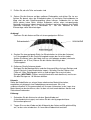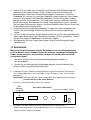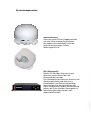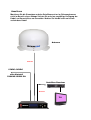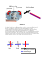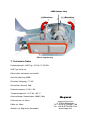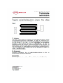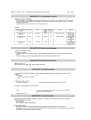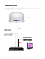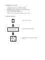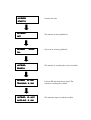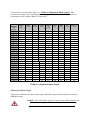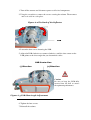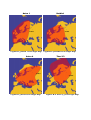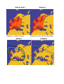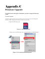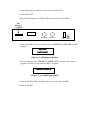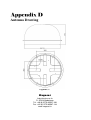
1
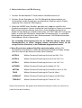
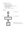
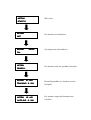
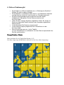
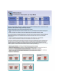
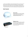
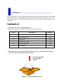
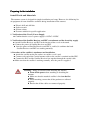
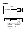
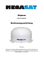
Shipman
WSTA-VM250P
Bedienungsanleitung
Achtung!
Bitte lesen Sie diese Bedienungsanleitung, bevor Sie die Antenne
installieren und in Betrieb nehmen, um Fehler bei der Montage und
Handhabung zu vermeiden.
Die Megasat VM250P ist eine automatische, selbst ausrichtende und nachführende
Satellitenantenne für die Satelliten Astra 1 (19,2°O), Eutelsat/Hotbird (13°O), Astra2
(28,2°O), Astra3 (23,5°O), Astra4/Sirius (4,8°O), Thor5/6 (0,8°W), Hispasat (30°W) und
Türksat (42°O).
Diese digitale Antenne ist somit die ideale Empfangslösung für Wohnmobil, Bus, LKW,
Schiff und PKW. Das Nachführungssystem ermöglicht auch Fernsehempfang während
der Fahrt. Die Antenne ist einfach zu montieren, sie wird mit einem Spezialkleber auf
das Dach aufgeklebt oder mit Schrauben befestigt.
Es führt nur ein Anschlusskabel zur Antenne.
Der kompakte Aufbau in Kuppelform und die niedrige Aufbauhöhe von ca. 40cm
machen diese Antenne absolut unempfindlich gegenüber Wind und muss nicht währen
der Fahrt abgebaut oder eingeklappt werden.
1. Lieferumfang
−
−
−
−
Kuppel-Antenne VM250P
Steuergerät inkl. Stromversorgungskabel
Antennenanschlusskabel
Schutzkappe für F-Stecker
Spezialklebeset inkl. Reiniger mit Primer und Applikator
2. Montage
Grundsätzlich empfehlen wir, den Einbau durch Ihren Fachhändler oder
eine Fachwerkstatt vornehmen zu lassen!
Beachten Sie bitte auch, dass sich durch die Antenne die Fahrzeughöhe
entsprechend ändert!
Wichtig!
Bitte halten Sie sich unbedingt an die einzelnen Punkte der
Montageanweisung! Beachten Sie bitte auch unsere
Gewährleistungshinweise!
Allgemeines:
Sorgen Sie für einen geeigneten Arbeitsplatz, eine Garage/Halle ist besser als ein Platz im
Freien. Die Umgebungstemperatur zur Montage soll zwischen +5°C und max.+25°C
liegen. Arbeiten Sie im Freien nicht in der Sonne. Halten Sie die Arbeitsvorschriften
beim Umgang mit Chemieprodukten ein. Sorgen Sie für die notwendige Arbeitshygiene.
Vorbereitung:
1. Vergewissern Sie sich, dass das Dach Ihres Fahrzeugs ausreichend stabil
ist. Bei ungenügender oder zweifelhafter Dachstabilität ist ein ca. 2mm
starkes Blech mit ca. 100 x 100 cm auf der Dachaußenhaut zu befestigen.
Erkundigen Sie sich dazu bei Ihrem Fahrzeughersteller.
Weiter Information finden Sie im Anhang unter „Verarbeitungshinweise“
2. Prüfen Sie, ob alle Teile vorhanden sind
3. Setzen Sie die Antenne auf den späteren Einbauplatz und richten Sie sie aus.
Achten Sie darauf, dass der Einbauplatz eben ist und keine Dachaufbauten im
Weg sind, die den Satellitenempfang stören können. Aufbauten bis zu 8cm
Höhe spielen keine Rolle, höhere Aufbauten sollten einen entsprechender
Abstand zur Antenne haben, damit kein Hindernis zwischen Antenne und Satellit
(minimale Elevation 16°-17°) vorhanden ist . Der min. Abstand zu einer
Klimaanlage sollte 30cm betragen.
Achtung!
Zeichnen Sie die Antennenfüße mit einem geeigneten Stift an.
4. Suchen Sie eine geeignete Stelle (im Windschatten im hinter der Antenne)
im Fahrzeugdach für die Durchführungsbohrungen der Anschlusskabel.
Achten Sie darauf, dass die Kabel nicht zu sehr gebogen werden (minimaler
Biegeradius ca. 5-7cm). Bohren Sie die Löcher vorsichtig in das
Fahrzeugdach.
5. Entfernen Sie die Antenne wieder.
Reinigen Sie die Montagefläche und die Antennenfüße mit einem Reiniger und
einem Vliestuch (Latexhandschuhe tragen). Schleifen Sie die Flächen und
Füße mit 120er Schleifpapier leicht an und reinigen Sie erneut mit dem
Reiniger (ACHTUNG: Flächen anschließend nicht mehr berühren) und lassen
Sie den Reinigen ca. 10 Minuten ablüften.
Hinweis:
Sollte die Klebefläche aus einem Ihnen unbekannten Material bestehen,
empfehlen wir dringend, eine Probeklebung vorzunehmen. Wir sind
selbstverständlich in Zusammenarbeit mit unserem Lieferanten in der Lage, eine
Materialanalyse durchzuführen, dies ist aber mit nicht unerheblichen Kosten und
Zeitaufwand verbunden.
Klebung:
1. Schneiden Sie die Kartusche mit dem Spezialkleber auf
(Latexhandschuhe tragen) und setzen Sie die schräg angeschnittene
Kartuschenspitze auf.
2. Tragen Sie nun den Kleber auf die Klebeseite der Antennenfüße gleichmäßig
auf, so dass eine mindestens 3-4 mm dicke Klebeschicht entsteht.
3. Setzen Sie nun sofort (max. innerhalb von 5 Minuten nach Kleberauftrag) die
Antenne auf die angezeichneten Felder. Drücken Sie die Füße leicht und
gleichmäßig an und fixieren Sie die Antenne gegen Verrutschen, z.B. durch
Klebeband. Es müssen sich nach dem Andrücken noch mindestens 2mm Kleber
zwischen Antennenfuß und Oberfläche befinden. Die Aushärtung des Klebers
beträgt maximal 48 Stunden bei +18°C und einer relativen Luftfeuchte von 50%.
Sollte während der Montagezeit sehr wenig Luftfeuchtigkeit herrschen, sprühen
Sie nach dem Aufsetzen der Antenne mit einem Sprüher etwas Wasser in die Luft
im dem Bereich der Antennenfüße.
4. Entfernen Sie die ausgetretene Klebemasse sofort mit einem Holzspatel und
wischen Sie verunreinigte Flächen mit einem Wischvliestuch und Reiniger
sauber.
5. Zu Ihrer Sicherheit können Sie die Antennenfüße mit je einer Schraube durch die
vorhandene Bohrung auf der Oberfläche zusätzlich sichern (empfohlen). Setzen
Sie die Schraube erst nach dem Aushärten des Klebers.
6. Bitte beachten Sie, dass noch etwas Kleber für die Durchführung der Kabel
benötigt wird.
3. Anschluss
Montieren Sie die Steuerbox und den Satellitenreceiver im Fahrzeuginneren
nicht im Bereich eines Airbags! Achten Sie auf eine sorgfältige Verlegung der
Kabel, um Kurzschlüsse zu vermeiden! Achten Sie hierbei auch auf schon
vorhandene Kabel!
1. Schließen Sie die Antenne mit dem beiliegenden Koaxialkabel an
der Steuerbox an.
2. Setzen Sie anschließend die Schutzkappe über die Anschlussbuchse der
Antenne (Schutz vor Witterungseinflüssen).
3. Verbinden Sie das Stromversorgungskabel mit der Box und der Stromquelle
(z.B. Fahrzeugbatterie). Das rote Kabel ist der Pluspol (+), das schwarze der
Minuspol (-).
ACHTUNG: Schließen Sie das Gerät immer über eine abgesicherte Leitung an
(niemals direkt an die Auto Batterie)
Anschluss für Receiver Anschluss für Antenne
SD
Memory
Card Slot
SD_CARD
Steuerbox (Rückseite)
Stromversorgung 12V5A
RS-232
RECEIVER
ANTENNA
12VDC 12VDC
IN
OUT
4. Schließen Sie den Satellitenreceiver gemäß der entsprechenden
Bedienungsanleitung an und verbinden Sie ihn nun mit dem kurzen KoaxialZwischenkabel mit der Steuerbox.
Systemkomponenten
Antenneneinheit
Unter der außen Einheit (Kuppel) befindet
sich eine 45cm Hochleistungsantenne.
Die elegante Kunstoffhaube schütz die
Antenne bestens gegen äußere
Witterungseinflüsse.
IDU (Steuergerät)
Mit der IDU wird das Antennensystem
gesteuert und mit Strom über das
Antennenkabel versorgt.
Das Steuergerät wird zwischen Antenne und
Receiver geschaltet und wird nur zur
Satellitenwahl und Ausrichtung benötigt.
Nach erfolgreicher Ausrichtung kann das
Gerät ausgeschaltet werden. Bei Benutzung
währen der Fahrt, wird das Steuergerät zur
Nachführung benötigt und darf nicht
abgeschaltet werden.
Anschluss
Montieren Sie die Steuerbox und den Satellitenreceiver im Fahrzeuginneren
nicht im Bereich eines Airbags! Achten Sie auf eine sorgfältige Verlegung der
Kabel, um Kurzschlüsse zu vermeiden! Achten Sie hierbei auch auf schon
vorhandene Kabel!
Antenne
Antenne
12VDC~24VDC
oder Netzteil
230VAC/12VDC 5A
Satelliten Receiver
Receiver
TV
4. Inbetriebnahme und Bedienung
1. Schalten Sie den Monitor/TV-Gerät und den Satellitenreceiver ein.
2. Schalten Sie die Steuerbox ein. Die IDU Überprüft die Kommunikation zur
Außeneinheit und die Anzeige des voreingestellten Satelliten wird im Display
angezeigt. Nun startet der Suchvorgang.
3. Wenn die VM250P einen Satelliten gefunden hat, stoppt sie und führt eine
Feinabstimmung durch. Danach leuchtet die Lock-Anzeige im Display auf und das
Bild erscheint auf Ihrem Monitor (falls Sie an Ihrem Satellitenreceiver einen
Sender im High-Band mit vertikaler Polarisation, z.B. PRO7 oder SAT1 eingestellt
haben, erscheint das Bild bereits während der Feinabstimmung). Im stehenden
Betrieb geht die Steuereinheit in den Stromsparmodus. Bei Betrieb während der
Fahrt bleibt das Gerät in Bereitschaft.
Der erstmalige Suchvorgang kann bis zu 5 Minuten dauern. Nach einem
Standortwechsel ist dieser Vorgang oftmals wesentlich kürzer, da die
vorige Position (Elevation) in der Steuerbox abgespeichert wurde.
4. Wenn Sie auf einen anderen Satelliten wechseln wollen, drücken Sie
die Satelliten Auswahltaste so oft bis der gewünschte Satellit im Display Anzeigt
wird. Nun wechselt die Antenne auf den neuen Satelliten.
ASTRA 2
Wählen Sie diese Einstellung für Astra2 auf 28,2° Ost.
ASTRA 3
Wählen Sie diese Einstellung für Astra 3 auf 23,5° Ost.
ASTRA 1
Wählen Sie diese Einstellung für Astra 1 auf 19,2° Ost.
HOTBIRD
Wählen Sie diese Einstellung für Hotbird 13° Ost.
ASTRA4
Wählen Sie diese Einstellung für Astra4/Sirius auf 4,8° Ost.
THOR
Wählen Sie diese Einstellung für Thor 0,8° West.
HISPASAT
Wählen Sie diese Einstellung für Hispasat auf 30° West.
TÜRKSAT
Wählen Sie diese Einstellung für Türksat 42° Ost.
Achten Sie darauf dass die gewünschte Satellitenrichtung freie Sicht zum Himmel hat.
(Orbit Position des Satelliten)
schlechter oder
kein Empfang
guter Empfang
Die Antenne wurde dafür entworfen, so effizient und so zuverlässig als möglich zu
arbeiten. Wenn die Antenne den ausgewählten Satelliten gefunden hat und die
Feinabstimmung beendet ist, geht das Steuergerät in den Standby Betrieb. Jetzt
können Sie die IDU ausschalten um unnötigen Stromverbrauch zu vermeiden. Die
Versorgung der Satellitenanlage erfolgt durch den Receiver und wird durch die IDU
geschliffen. Bei fahrendem Betrieb, darf die IDU nicht abgeschaltet werden.
Funktion LCD Display
Power S/W
ON
OFF
LCD Display
MEGASAT
Drücken bis die gewünschte Satellitenanzeige leuchtet.
SATELLITE
SELECT
SLEEP
POWER
Standby
Erklärung der LCD Anzeige
- INIT : Initialisierung der Antenne.
- INIT-SCH : Anfangssuchmodus.
- SAT-MOVE: Wechselt zu einem anderen Satelliten.
- S:xxx : Intensität des Signala.
- ID:xxx : ID des Satelliten.
- GYRO-CAL : Kalibrierung Gyro Sensor.
Allgemein
ON
OFF
Gerät Einschalten.
POWER
Information der IDU.
Information of IDU
Drücken der Satellitenauswahltaste
SATELLITE
SELECT
Bis der gewünscht Satellit angezeigt wird.
ASTRA1
IDU startet.
START !!!
ASTRA1
Die Antenne wird initialisiert.
INIT
ASTRA1
GYROGYRO-
Gyroskopsensor wird kalibriert.
CAL
ASTRA1
SEARCH…
SEARCH
ASTRA1
ID : AS1
AS1
Die Antenne sucht den gewählten Satelliten.
ID und Signalstärke des Satelliten werden
TRACKING S : 288
überprüft.
ASTRA1
Die Antenne stoppt und übernimmt den
Satelliten.
ID : AS1
AS1
AUTOAUTO-SLP S : 288
Im Falle einer fehlerhaften Suche
Die Antenne sucht den gewünschten Satelliten.
ASTRA1
SEARCH…
SEARCH
Wenn der Satellit innerhalb von 2 Minuten
nicht gefunden wird, beginnt die Suche von
vorne..
ASTRA1
INITINIT-SLP
ASTRA1
Die Antenne sucht den gewünschten Satelliten.
SEARCH…
SEARCH
ASTRA1
ID : AS1
ID und Signalstärke des Satelliten werden
TRACKING S : 288
überprüft.
ASTRA1
Die Antenne stoppt und übernimmt den
Satelliten.
ID : AS1
AUTOAUTO-SLP S : 288
6. Falls es Probleme gibt
•
•
•
•
•
•
•
Sind Hindernisse (Bäume Gebäude usw.) in Richtung des Satelliten?
Wählen Sie einen anderen Standort.
Sind Gebäude in unmittelbarer Nähe kann es zu Reflektionen kommen
und die Antenne richtet sich nicht korrekt aus (Standort wechseln)
Sind die Antennenkabel korrekt angeschlossen oder defekt
(Kabelbruch)? Überprüfen Sie die Antennenstecker und Anschlusskabel.
Haben Sie den richtigen Satelliten angewählt? Prüfen Sie, ob der im
Receiver eingestellte Satellit mit dem in der Steuerbox angewählten
übereinstimmt.
Ist die Steuerbox/Sat-Receiver eingeschaltet?
Ist die Stromversorgung angeschlossen? Kontrollieren sie die
Anschlusskabel.
Skew Einstellung anpassen. (siehe Tabelle)
Je nach Standort kann es erforderlich sein den Skew entsprechend Ihrer
Position nachzustellen.
Europa Position - Raster
Bitte entnehmen Sie der Tabelle Ihre Postion (1-25)
Die Skew Anpassung (LNB Winkel), finden Sie in der Liste (Skew Anpassung) .
Skew Anpassung
Um die korrekte Skew Einstellung vorzunehmen, entfernen Sie die Kuppel der Antenne und
lösen beide Schrauben der LNB Halterung so weit, dass das LNB sich drehen lässt.
Bewegen Sie jetzt das LNB entsprechend der Tabelle auf die richtige Position und befestigen
Sie die Schrauben der LNB Halterung. Anschließend schließen Sie die Kuppel wieder.
Hinweis: Diese Einstellung müssen Sie nur einmalig bei größeren Abweichungen vornehmen.
Rast
er
Pos.
1
2
3
4
5
6
7
8
9
10
11
12
13
14
15
16
17
18
19
20
21
22
23
24
25
ASTRA2
N
28.2°E
ASTRA2
S
28.2°E
ASTRA3
23.5°E
ASTRA1
19.2°E
HOTBI
RD
13.0°E
ASTRA4
4.8°E
THOR
0.8°W
HISPAS
AT
30°W
TURKS
AT
42°E
13°
10°
6°
1°
-2°
17°
13°
8°
2°
-3°
21°
17°
10°
2°
-4°
27°
21°
12°
3°
-5°
33°
26°
16°
4°
-6°
13°
10°
6°
1°
-2°
17°
13°
8°
2°
-3°
21°
17°
10°
2°
-4°
27°
21°
12°
3°
-5°
33°
26°
16°
4°
-6°
11°
8°
4°
-1°
-4°
14°
10°
5°
-1°
-6°
18°
13°
6°
-1°
-7°
23°
17°
8°
-2°
-9°
29°
21°
10°
-2°
-11°
10°
6°
2°
-3°
-6°
12°
8°
2°
-3°
-8°
16°
10°
3°
-4°
-10°
20°
14°
4°
-6°
-13°
25°
17°
5°
-7°
-16°
7°
4°
-1°
-5°
-9°
9°
5°
-1°
-7°
-11°
12°
6°
-2°
-9°
-14°
15°
8°
-2°
-11°
-18°
19°
10°
-2°
-14°
-23°
3°
0°
-4°
-9°
-12°
4°
0°
-6°
-11°
-15°
6°
0°
-7°
-15°
-20°
8°
0°
-10°
-18°
-25°
9°
0°
-12°
-23°
-30°
1°
-3°
-7°
-11°
-14°
1°
-3°
-9°
-14°
-18°
2°
-4°
-11°
-18°
-23°
2°
-6°
-15°
-23°
-28°
3°
-7°
-18°
-28°
-34°
-11°
-14°
-18°
-20°
-22°
-15°
-18°
-22°
-25°
-27°
-19°
-23°
-28°
-32°
-34°
-23°
-29°
-34°
-38°
-41°
-29°
-35°
-41°
-45°
-48°
-11°
-14°
-18°
-20°
-22°
-15°
-18°
-22°
-25°
-27°
-19°
-23°
-28°
-32°
-34°
-23°
-29°
-34°
-38°
-41°
-29°
-35°
-41°
-45°
-48°
LNB Center Line
(-) Direction
Satelliten Signal
(+) Direction
LNB Signal
Die Signale Vertikal (rot) und Horizontal (blau) werden in einem genauen Winkel von 90°
gesendet. Die Signale des Satelliten werden im selben Kreuzmuster gesendet.
Um einen optimalen Empfang zu erreichen müssen beide Elemente im gleichen Winkel
zueinander stehen. Je genauer die Übereinstimmung desto besser der Empfang.
Diese Einstellung nennt man Skew Einstellung. Da sich diese Einstellung entsprechend Ihrem
Standort ändert (siehe Tabelle), muss der Skew um eine optimale Ausrichtung zu erreichen
Angepasst werden. Systeme mit automatischer Skew Einstellung führen das LNB selbständig
nach. Bei manuellen Systemen, muss das per Hand vorgenommen werden.
Bad
Good
Best
: LNB “Signal collector”
: Satellite Signal
LNB Center Line
(-) Direction
(+) Direction
Skew Anpassung
7. Technische Daten
Frequenzbereich: LNB-Typ: 10,7 bis 12,75 GHz
LNB Typ: Universal
Polarisation: horizontal und vertikal
Gain/Verstärkung: 33dBi
Elevation (Neigung): 17° 60°
Suchwinkel (Azimut): 360°
Stromversorgung: 12-24V / 5A
Temperaturbereich: -22°C bis +55° C
Antennenkabel: Koaxialkabel 100dB (10m)
Durchmesser: ca. 68cm
Höhe: ca. 40cm
Gewicht: ca. 9kg (ohne Steuerbox):
Megasat
Industriestrasse 4a
D- 97618 Niederlauer
Tel. +49 (0) 9776 63567-100
Fax. +49 (0) 9776 63567-144
www.megasat.tv
Verarbeitungshinweise
Shipman
WSTA-VM250P
User Manual
1
Introduction
Specification………………….…………………………………………………….
Antenna System Overview…………………………………………………….
Direct Broadcast Satellite Overview………………………….…………..
System Components……………………………………………………………
2
Installation
Unpacking the Unit………………………………..…………………….......
Preparing for the installation……………………………………………….
Selecting the location………….……………………………………….……...
Equipment and cable installation…………..…………………………….
Setting the LNB Skew Angle(Manual Skew version only)………..
3
Operation
Receiving Satellite TV Signals…………….……………………………….
Turning the System On/Off…………..………………..…………………..
Changing Channels………………………….…………………...…..………..
Watching TV…………………………………………………………..……..…..
Switching between Satellites………………………………………………..
Operating the IDU……………………………………….…………………..
4
Troubleshooting
Simple Check……………………………………………..………………….
Causes and Remedies……………………………….……..……………….
1
Appendix A
How to set the skew angle……………………………………………..…….
2
Appendix B
Satellite Coverage Map…………………..………………………..…….
3
Appendix C
Firmware Upgrade…………………….………………………………….
4
Appendix D
Antenna Drawing …………………….………………………………….
Notes, Cautions, and Warnnings
Caution – Improper handling by unqualified personnel can cause serious
damage to this equipment. Unqualified personnel who tamper with
this
equipment may be held liable for any resultant damage to the
equipment.
Install under DRY condition ONLY! Do not install this system in the
rain,
or under any wet conditions. Moisture may affect electronics and
void warrenty!
Warning – Need 2 people to install the antenna onto the roof. Do not try to
install the antenna by yourself.
Note – Before you begin, carefully read each of the procedures in
this manual. If you have not performed similar operations on
comparable equipment, do not attempt to perform these procedures.
The satellite antenna system is the innovative and a technologically advanced satellite InMotion system. The antenna has a unique combination of state-of-the art components with the
most sophisticated satellite acquisition and tracking programs to provide the following
features:
■
■
■
■
■
Fast satellite acquisition
Compatible with any Satellite Receiver
Compatible with all Direct Broadcast Satellites (DBS)
Built-in Digital Broadcast Receiver(DVB)
Capable of High Definition receiving
Specification………………….…………………………………………………….
Antenna System Overview…………………………………………………….
Direct Broadcast Satellite Overview………………………….…………..
System Components……………………………………………………………
Specification
Antenna Type
Parabola
Frequency Band
Ku Band
Radome Dimension
390x700mm
Antenna Weight
9kg
Antenna Gain
33dBi
Minimum EIRP
49dBW
Polarization
V/H or RHCP/LHCP
Type of Stabilization
2-Axis Step Motor
Elevation Range
19° to 64°
Azimuth Range
Unlimited
Tracking Rate
50°/sec
Temperate Range
-20° to 70°
Power
12~24VDC
Table 1-1 Specification
Antenna System Overview
A complete satellite TV system, illustrated in Figure 1-1, includes the antenna connected to a
IDU, a satellite TV receiver, and a television set.
Antenne
Antenne
Vehicle power
12VDC~24VDC
or power supply
230VAC/12VDC 5A
Satellite Receiver
Receiver
TV
Direct Broadcast Satellite Overview
Direct Broadcast Service (DBS) satellites broadcast audio, video and data information from
satellites located 22,000 miles in space. A receiving station, such as the antenna, should
include a dish and satellite receiver to receive the signals and process them for use by the
consumer audio and video equipment. The system requires a clear view of the satellite to
maximize the signal reception.
Blocked !
Free !
good signal !
Figure 1-2 Satellite Blockage
bad or no signal !
Objects such as tall lighthouse, bridges and big ship that block this view will cause a loss of
signal. The signal will be quickly restored once the antenna has a clear line of sight again.
Heavy rain, cloud, snow or ice may also interfere with the signal reception quality. If the
satellite signal is lost due to blockage or severe weather condition, services from the receiver
will be lost (picture will freeze frame and may disappear). When the satellite signal strength
is again high enough, then the receiver will resume providing desired programming services.
System Components
Antenna Unit
The antenna unit houses the antenna positioning
mechanism, LNB (low noise block), and control
elements within a radome. Weather tight
connectors join the power, signal, and control
cabling from the below deck units.
IDU(InDoor Unit)
The IDU is the system’s user interface, providing
access to the system and its functions through an
LCD and three buttons. The IDU also serves as
the vessel’s junction box, allowing the system to
use vessel power, and supply and receive data
to/from the antenna unit.
Figure 1-3 System
Components
This section offers a general explanation of how properly to install the antenna. Installation of
the antenna must be accomplished by or under the supervision of an authorized dealer for the
Limited Warranty to be valid and in force. The steps in the installation and setup process are
as follows:
Unpacking the unit
1. Open box and remove packing material.
The following items are included in the packaging of the antenna.
Item
Description
Quantity
1
Antenna Unit
1 each
2
IDU(In Door Unit)
1 each
3
Power Cable
1 each
4
Coaxial Cable (10m)
1 each
5
Coaxial Cable (1m)
1 each
6
User Manual
1 set
Table 2-1 Parts included
2. Lift dome out of box vertically. Then lift unit out of box vertically. Do not turn box
and “roll” out, or turn upside down to remove.
Lift Unit straight
up out of the
carton!
Figure 2-1 Unpacking the unit
Preparing for the installation
Install Tools and Materials
The antenna system is designed for simple installation and setup. However, the following list
of equipment or items should be available during installation of the antenna.
■
■
■
■
Electric drill and drill bits
Socket wrench
Silicon sealant
Fastener suitable for specific application
1. Verification of the Vessel’s Power Supply.
■ Confirm that the vessel’s power supply is 12VDC~24VDC.
2. Verification of the Satellite Receiver and IDU’s attachment and the electricity supply
■ Attach Satellite Receiver and IDU in the interior of the vessel or the trunk.
■ Connect the power of Satellite Receiver and IDU.
■ Once the power of Satellite Receiver and IDU is verified, it confirms that both
Satellite Receiver and IDU are working normally.
3. Procedure of the satellite’s attachment and installation.
■ Attach the satellite on the flat surface area of the vessel’s roof.
■ Connect each end of the Coaxial antenna cable to the satellite’s terminal and the IDU.
■ Connect the IDU and the Satellite Receiver box together through the coaxial cable.
■ Make sure that the satellite is working normally, once the power is supplied.
Warning : Things to consider when installing the antenna.
■ Turn off the power when attaching or detaching the
antenna.
■ Make sure that the attached satellite is fixed on the flat
surface.
■ When attaching, ensure that all the products are adhered
properly.
■ Ensure that all the cables are connected properly.
Selecting the location
Determine the optimum mounting location for the antenna radome assembly. It should be
installed where:
1. The antenna has a clear line-of-sight view to as much of the sky as is practical. Choose
a location where masts or other structures do not block the satellite signal from the dish
as the vessel turns.
2. The antenna is at least 5 feet away from other transmitting antennas (HF, VHF and
radar) that may generate signals that may interfere with the antenna. The further away
the antenna is from these other antennas, the less impact their operation will have on it.
3. Direct radiation into the antenna from vessels radar, especially high power surveillance
radar arrays, is minimized. The radome should be as far away from the vessels Radar as
possible and should NOT be mounted on the same plane as the vessels Radar.
4. The antenna radome assembly should be rigidly mounted to the vessel. If necessary,
reinforce the mounting area to assure that it does not flex due to the vessel motion or
vibration.
If these conditions cannot be entirely satisfied, the site selection will inevitably be a “best”
compromise between the various considerations.
Perform a through site inspection on the roof for the antenna to be mounted.
1. The antenna must have a clear view of the sky and the horizon at all
the directions to avoid blockage of the satellite signal.
2. The antenna should be on the top of the vehicle.
Best
Location
Poor
Location
Figure 2-2 Selecting the location
Equipment and cable installation
This offers a general explanation of how to install the IDU and satellite receiver properly to
the inside of vessel connecting with coaxial cable.
1. The Coaxial cable is routed from the antenna to the IDU inside the vessel.
2. After Once deciding where to place the IDU and satellite receiver, make sure that both
units are placed in a dry and protected area.
3. The IDU and satellite receiver should be placed away from any heat source and in an
area with proper ventilation.
4. Ensure that there are at least 3cm of space around both units for ventilation and
connection of cables. Do not stack the units on top of each other.
5. The following describes the basic wiring configurations for the antenna system.
■ Connect the Coaxial cable to the antenna port on the back of the IDU
■ Connect one end of the supplied coaxial cable to the receiver port on the back of
the IDU
■ Connect the other end of the coaxial cable to the satellite receiver
Setting the LNB skew angle (manual)
Figure 2-3 Satellite signals
Signals transmitted in vertical(red) and horizontal(blue) wave offset exactly 90º from each
other. Since linear satellite signals are oriented in a precise cross pattern, Free Way 1S
antenna’s receiving element, called an LNB (low-noise block) must be oriented in the same
way to optimize reception. This orientation adjustment is referred to as the LNB’s “skew
angle.” Figure 1-4 illustrates how skew determines the amount of signal the LNB collects.
The more signal, the better reception.
Bad
skew
Good
skew
Figure 2-4 Best Skew Angle
Best
skew
: LNB “signal collector”
: Satellite Signal
The correct skew setting varies depending on your geographic location, since the orientation
of your antenna to the satellite changes as you move. For complete details about adjusting the
LNB’s skew angle, see “Appendix A – How to Set the Skew Angle”
The antenna system is easy to use. Under normal conditions, operation of the antenna
requires no intervention from the user. Antenna unit initialization and satellite acquisition is
completely automatic.
Receiving Satellite TV Signal….………………………………………….20
Turning the System On/Off……………………………………………….20
Changing Channels…………….……………………………………….……..21
Watching TV…………………………….…………..……………………………21
Switching between Satellites…………………..………………………….21
Operating the IDU…..…………………………..……………………………22
Receiving Satellite TV Signals
Television satellites are located in fixed positions above the Earth’s equator and beam TV
signals down to certain regions of the planet. To receive TV signals from a satellite, you must
be located within that satellite’s unique coverage area. To check it, see “Appendix B –
Satellite Coverage Map” In addition, since TV satellites are located above the equator, the
antenna must have a clear view of the sky to receive satellite TV signals. Anything that stands
between the antenna and the satellite can block the signal, resulting in lost reception.
Common causes of blockage include lighthouses, boat masts, trees, buildings, and bridges.
Heavy rain, ice, or snow might also temporarily interrupt satellite signals.
Turning the System On/Off
Since power to the antenna system is controlled by the IDU, you can turn the antenna on or
off by applying/removing operating power to the IDU.
Turning on the System
Follow the steps below to turn on your antenna System.
1. Make sure the antenna has a clear view of the sky.
2. Turn on your satellite TV receiver and TV.
3. Apply operating power to the IDU.
4. Wait one minute for system startup. The IDU will display the Tracking
Satellite screen after system testing is complete.
Turning off the System
Follow the steps below to turn off your antenna System.
1. Remove operating power from the IDU.
2. Turn off your satellite TV receiver and TV.
Changing Channels
If you have followed the installation instructions, your system should be set to the satellite of
your choice and the system should have downloaded the appropriate channel guides. When
the antenna system and satellite receiver is properly configured, it is easy to change the
channel using the remote control that normally comes with the receiver unit.
Watching TV
The antenna is designed to operate as efficiently and as reliably as possible when the vessel
is moved and anchored. It is also the quickest satellite acquisition system available among the
antennas. If you have anchored the vessel and the antenna has completed to searching selected
satellite, turn off IDU Power to avoid unnecessary use of power. Because the LNB receives its
power from the Satellite Receiver through the IDU, the antenna will continue to receive the
satellite TV signals.
Switching between Satellites
You can switch between satellites using the IDU by pressing Satellite select buttons. Follow
the steps below to switch to another satellite.
1. Ensure that the LCD screen of the IDU is displayed.
HOTBIRD
ID: HOT
AUTO_SLP S : 280
Figure 3-1 IDU LCD Screen
2. Press the Satellite select buttons to switch to another satellite.
3. The antenna shifts to track selected satellite. Wait for the Tracking Satellite
screen to reappear with the ID of selected satellite displayed.
Operating the IDU
Appearance
Power S/W
ON
OFF
LCD Display
MEGASAT
SATELLITE
SELECT
SLEEP
POWER
Satellite select button
Sleep button
Figure 3-2 Appearance of IDU
Functions of LCD Display
ON
OFF
MEGASAT
SATELLITE
SELECT
SLEEP
POWER
Zoom in
It shows user
selected satellite
It shows satellite ID
It shows current
operational status
It shows intensity of
signal
Figure 3-3 Functions of LCD Display
Explanation of words in LCD
- INIT : It shows condition of initializing the antenna.
- INIT-SCH : It shows condition of initial search mode.
- SAT-MOVE: It shows condition of moving to another satellite.
- S:xxx : It shows intensity of signal.
- ID:xxx : It shows ID of acquired satellite.
- GYRO-CAL : It shows condition of calibrating the Gyro Sensor.
General Operation Order
ON
OFF
Turn the power switch on.
POWER
Information of IDU
SATELLITE
SELECT
LCD shows information of IDU.
Push the Satellite select buttons to choose
satellite.
HOTBIRD
It notice the start.
START !!!
HOTBIRD
The antenna is being initialized.
INIT
HOTBIRD
GYROGYRO-
Gyro sensor is being calibrated.
CAL
HOTBIRD
The antenna is searching the selected satellite.
SEARCH…
SEARCH
HOTBIRD
ID : HOT
TRACKING S : 288
It shows ID and intensity of signal. The
antenna is tracking the satellite.
HOTBIRD
The Antenna stops to track the satellite.
ID : HOT
AUTOAUTO-SLP S : 288
In case of search failure
HOTBIRD
The antenna is searching the selected satellite.
SEARCH…
SEARCH
INITINIT-SLP
If the antenna cannot search the signal, it stops
to search during 2 minutes and repeat
searching the satellite.
HOTBIRD
The antenna is searching the selected satellite.
HOTBIRD
SEARCH…
SEARCH
HOTBIRD
ID : HOT
It shows ID and intensity of signal. The
antenna is tracking the satellite.
TRACKING S : 288
HOTBIRD
ID : HOT
AUTOAUTO-SLP S : 288
The Antenna stops to track the satellite.
There are a number of common issues that can affect the signal quality or the operation of
the antenna system. The following sections address these issues and potential solutions.
Simple check………………….….………………………………………….
Causes and Remedies…..………………..………………………………….
Simple check
Can the antenna see the satellite?
The antenna requires an unobstructed view of the sky to receive satellite TV
signals. Common causes of blockage include trees, buildings, bridges, and
mountains.
Is there excessive dirt or moisture on the antenna dome?
Dirt buildup or moisture on the dome can reduce satellite reception. Clean the
exterior of the dome periodically.
Is it raining heavily?
Heavy rain or snow can weaken satellite TV signals. Reception should improve
once the inclement weather subsides.
Is everything turned on and connected properly?
Make sure your TV and receiver are both turned on and set up for the satellite
input. Finally, check any connecting cables to ensure none have come loose.
Is the antenna’s LNB set to the correct skew angle? (Manual Skew Ver. Only)
To optimize reception, the antenna’s LNB needs to be set to the correct skew angle
for the satellite you want to track. See “Appendix A – How to set the skew
angle” for details
Causes and Remedies
Receiver Fault
Your satellite TV receiver might be set up incorrectly or defective. First check the
receiver’s configuration to ensure it is set up for the desired programming. In the
case of a faulty receiver, refer to your selected receiver’s user manual for service
and warranty information.
Satellite Coverage Issue
Television satellites are located in fixed positions above the Earth’s equator and
beam TV signals down to certain regions of the planet (not worldwide). To receive
TV signals from a satellite, you must be located within that satellite’s unique
coverage area. See “Appendix-B Satellite Coverage Map”
Satellite Signal Blocked
The Antenna needs a clear line of sight (LOS), view to the satellite for
uninterrupted reception. Objects such as tall lighthouse, bridges and big ship that
block this view will cause a loss of signal. The signal will be quickly restored once
the antenna has a clear line of sight again. Heavy rain, cloud, snow or ice may also
interfere with the signal reception quality. If the satellite signal is lost due to
blockage or severe weather condition, services from the receiver will be lost
(picture will freeze frame and may disappear). When the satellite signal strength is
again high enough, then the receiver will resume providing desired programming
services.
Satellite Frequency Data Changed
If some channels work, while one or more other channels do not, or if the antenna
cannot find the selected satellite, the satellite’s frequency data might have
changed. You can visit any WIWORLD-authorized dealer or distributor for
assistance or visit http://www.wiworld.co.kr
Improper Wiring
If the system has been improperly wired, the antenna will not operate correctly.
Refer to the User Manual for complete system wiring information or visit website
(http://www.wiworld.co.kr)
Loose Cable Connectors
We recommend periodically checking the antenna unit’s cable connections. A
loose cable connector can reduce signal quality or prevent automatic satellite
switching using the receiver’s remote control. Fasten the cable connector.
How to Set up the Skew Angle
Signals transmitted in vertical and horizontal wave offset exactly 90º
from each other. Since linear satellite signals are oriented in a precise
cross pattern, the antenna’s receiving element, called an LNB (low-noise
block) must be oriented in the same way to optimize reception. This
orientation adjustment is referred to as the LNB’s “skew angle.” The
correct skew setting varies depending on your geographic location, since
the orientation of your antenna to the satellite changes as you move. This
appendix provides how to set up the skew angle.
European
European Position Grid
If you wish to determine the Skew Angle(LNB), use the position grid(Figure A-1
European Positon Grid) and table(TableA-1 Regional Skew angle).
Figure A-1 Europe Position Grid
If you wish to set the correct skew, see “TableA-1 Regional Skew angle”. The
correct skew setting varies depending on your geographic location, since the orientation of
your antenna to the satellite changes as you move.
Raster
Position
Grid
Position
TURKSA
T
43°E
ASTRA2
28.2°E
ASTRA3
23.5°E
ASTRA1
19.2°E
HOTBIR
D
13.0°E
Astra4
4.8°E
THOR
0.8°W
AB3
5.0°W
HISPASAT
30°W
1
2
3
4
5
6
7
8
9
10
11
12
13
14
15
16
17
18
19
20
21
22
23
24
25
17°
14°
11°
6°
2°
22°
19°
15°
8°
1°
29°
25°
20°
10°
1°
35°
30°
24°
13°
1°
41°
36°
29°
16°
2°
13°
10°
6°
1°
-2°
17°
13°
8°
2°
-3°
21°
17°
10°
2°
-4°
27°
21°
12°
3°
-5°
33°
26°
16°
4°
-6°
11°
8°
4°
-1°
-4°
14°
10°
5°
-1°
-6°
18°
13°
6°
-1°
-7°
23°
17°
8°
-2°
-9°
29°
21°
10°
-2°
-11°
10°
6°
2°
-3°
-6°
12°
8°
2°
-3°
-8°
16°
10°
3°
-4°
-10°
20°
14°
4°
-6°
-13°
25°
17°
5°
-7°
-16°
7°
4°
-1°
-5°
-9°
9°
5°
-1°
-7°
-11°
12°
6°
-2°
-9°
-14°
15°
8°
-2°
-11°
-18°
19°
10°
-2°
-14°
-23°
3°
0°
-4°
-9°
-12°
4°
0°
-6°
-11°
-15°
6°
0°
-7°
-15°
-20°
8°
0°
-10°
-18°
-25°
9°
0°
-12°
-23°
-30°
1°
-3°
-7°
-11°
-14°
1°
-3°
-9°
-14°
-18°
2°
-4°
-11°
-18°
-23°
2°
-6°
-15°
-23°
-28°
3°
-7°
-18°
-28°
-34°
-1°
-4°
-9°
-12°
-15°
-1°
-6°
-11°
-16°
-20°
-2°
-8°
-14°
-21°
-25°
-2°
-10°
-18°
-26°
-31°
-2°
-12°
-23°
-32°
-37°
-11°
-14°
-18°
-20°
-22°
-15°
-18°
-22°
-25°
-27°
-19°
-23°
-28°
-32°
-34°
-23°
-29°
-34°
-38°
-41°
-29°
-35°
-41°
-45°
-48°
Table A-1 Regional Skew Angle
Setting the Skew Angle
If you have determine the correct skew angle, follow the steps below to adjust the antenna’s
LNB skew angle.
Caution – To avoid bodily injury, be sure to turn off the antenna and
disconnect power to all wore components.
1. Turn off the antenna and disconnect power to all wired components.
2. Using the screwdriver, remove the screws securing the radome. Then remove
and set it aside in a safe place.
Figure A-2 The Back of the Reflector
LNB
4. Loosen the four screws fastening the LNB.
5. Adjust the LNB clockwise or counter-clockwise, until the skew arrow on the
LNB points to the skew angle that you determined earlier.
LNB Center Line
(-) Direction
(+) Direction
Caution
Be sure to keep the LNB fully
inserted into the hall to ensure
the optimum performance.
Figure A-3 LNB Skew Angle Adjustment
6. Tighten the four screws.
7. Reinstall the radome.
Satellite Coverage Map
Television satellites are located in fixed positions above
the Earth’s equator and beam TV signals down to certain
regions of the planet (not worldwide). To receive TV
signals from a satellite, you must be located within that
satellite’s unique coverage area.
Satellite Coverage Map
Satellite TV broadcast spot beams are aimed at land masses where the bulk of subscribers can
be found. Thus, the signal strength decreases as you travel away from the land masses. The
further you travel offshore you will require a larger size antenna. Although this information is
believed to be correct, WIWORLD Technologies has no control over the variations on the
actual satellite footprint coverage. Signal strength and reception can be affected by the
weather conditions.
Astra 2N
Astra 2S
49dBW
49dBW
Figure B-1 Astra 2N Coverage Map
Coverage Map
Figure B-2 Astra 2S
Astra 1
Hotbird
49dBW
49dBW
Figure B-3 Astra 1 Coverage Map
Astra 4
Figure B-4 Hotbird Coverage Map
Thor 2/3
49dBW
49dBW
Figure B-5 Sirius Coverage Map
Figure B-6 Thor 2/3 Coverage Map
Atlantic Bird 3
49dBW
Figure B-7 Atlantic bird 3
ASTRA 3
Hispasat
49dBW
Figure B-8 Astra 2S Coverage Map
TURKSAT
Firmware Upgrade
If satellite beam is changed or eliminated, you have to upgrade firmware
of IDU.
Firmware Upgrade
If antenna cannot search the selected satellite or move incorrectly, you need to change the
firmware of IDU. To upgrade the firmware, follow the steps below.
1. Prepare the SD memory card.
Figure C-1 SD memory card
2. Before you use the SD memory card, you should format it to “FAT16(Default)”
Figure C-2 Formatting SD memory card
3. After formatting your SD card, copy the new software file .
4. Turn off the IDU.
5. Put your SD memory card into the SD slot of back side of the IDU.
SD
Memory
Card Slot
SD_CARD
RS-232
RECEIVER ANTENNA
12VDC
Figure C-3
The back of the IDU
IN
12VDC
OUT
6. Turn on the IDU. You can see the message “WRITING SOFTWARE” in LCD
Display.
WRITING
SOFTWARE
Figure C-4 Writing software
7. If you see the message “FINISH TO WRITE”, IDU is finishing the software
upgrade. You have to wait until the IDU is restarted.
FINISH TO WRITE
Figure C-5 Finishing to write
8. Turn off the IDU. Take your SD memory card away from the IDU.
9. Turn on the IDU.
Antenna Drawing
Figura C-1
Megasat
Industriestrasse 4a
D- 97618 Niederlauer
Tel. +49 (0) 9776 63567-100
Fax. +49 (0) 9776 63567-144
www.megasat.tv