1
Cisco 7500 Series Installation and
Configuration Guide
Corporate Headquarters
Cisco Systems, Inc.
170 West Tasman Drive
San Jose, CA 95134-1706
USA
http://www.cisco.com
Tel: 408 526-4000
800 553-NETS (6387)
Fax: 408 526-4100
Customer Order Number:
Text Part Number: OL-5008-03 B0
THE SPECIFICATIONS AND INFORMATION REGARDING THE PRODUCTS IN THIS MANUAL ARE SUBJECT TO CHANGE WITHOUT NOTICE. ALL
STATEMENTS, INFORMATION, AND RECOMMENDATIONS IN THIS MANUAL ARE BELIEVED TO BE ACCURATE BUT ARE PRESENTED WITHOUT
WARRANTY OF ANY KIND, EXPRESS OR IMPLIED. USERS MUST TAKE FULL RESPONSIBILITY FOR THEIR APPLICATION OF ANY PRODUCTS.
THE SOFTWARE LICENSE AND LIMITED WARRANTY FOR THE ACCOMPANYING PRODUCT ARE SET FORTH IN THE INFORMATION PACKET THAT
SHIPPED WITH THE PRODUCT AND ARE INCORPORATED HEREIN BY THIS REFERENCE. IF YOU ARE UNABLE TO LOCATE THE SOFTWARE LICENSE
OR LIMITED WARRANTY, CONTACT YOUR CISCO REPRESENTATIVE FOR A COPY.
The following information is for FCC compliance of Class A devices: This equipment has been tested and found to comply with the limits for a Class A digital device, pursuant
to part 15 of the FCC rules. These limits are designed to provide reasonable protection against harmful interference when the equipment is operated in a commercial
environment. This equipment generates, uses, and can radiate radio-frequency energy and, if not installed and used in accordance with the instruction manual, may cause
harmful interference to radio communications. Operation of this equipment in a residential area is likely to cause harmful interference, in which case users will be required
to correct the interference at their own expense.
The following information is for FCC compliance of Class B devices: The equipment described in this manual generates and may radiate radio-frequency energy. If it is not
installed in accordance with Cisco’s installation instructions, it may cause interference with radio and television reception. This equipment has been tested and found to
comply with the limits for a Class B digital device in accordance with the specifications in part 15 of the FCC rules. These specifications are designed to provide reasonable
protection against such interference in a residential installation. However, there is no guarantee that interference will not occur in a particular installation.
Modifying the equipment without Cisco’s written authorization may result in the equipment no longer complying with FCC requirements for Class A or Class B digital
devices. In that event, your right to use the equipment may be limited by FCC regulations, and you may be required to correct any interference to radio or television
communications at your own expense.
You can determine whether your equipment is causing interference by turning it off. If the interference stops, it was probably caused by the Cisco equipment or one of its
peripheral devices. If the equipment causes interference to radio or television reception, try to correct the interference by using one or more of the following measures:
• Turn the television or radio antenna until the interference stops.
• Move the equipment to one side or the other of the television or radio.
• Move the equipment farther away from the television or radio.
• Plug the equipment into an outlet that is on a different circuit from the television or radio. (That is, make certain the equipment and the television or radio are on circuits
controlled by different circuit breakers or fuses.)
Modifications to this product not authorized by Cisco Systems, Inc. could void the FCC approval and negate your authority to operate the product.
The Cisco implementation of TCP header compression is an adaptation of a program developed by the University of California, Berkeley (UCB) as part of UCB’s public
domain version of the UNIX operating system. All rights reserved. Copyright © 1981, Regents of the University of California.
NOTWITHSTANDING ANY OTHER WARRANTY HEREIN, ALL DOCUMENT FILES AND SOFTWARE OF THESE SUPPLIERS ARE PROVIDED “AS IS” WITH
ALL FAULTS. CISCO AND THE ABOVE-NAMED SUPPLIERS DISCLAIM ALL WARRANTIES, EXPRESSED OR IMPLIED, INCLUDING, WITHOUT
LIMITATION, THOSE OF MERCHANTABILITY, FITNESS FOR A PARTICULAR PURPOSE AND NONINFRINGEMENT OR ARISING FROM A COURSE OF
DEALING, USAGE, OR TRADE PRACTICE.
IN NO EVENT SHALL CISCO OR ITS SUPPLIERS BE LIABLE FOR ANY INDIRECT, SPECIAL, CONSEQUENTIAL, OR INCIDENTAL DAMAGES, INCLUDING,
WITHOUT LIMITATION, LOST PROFITS OR LOSS OR DAMAGE TO DATA ARISING OUT OF THE USE OR INABILITY TO USE THIS MANUAL, EVEN IF CISCO
OR ITS SUPPLIERS HAVE BEEN ADVISED OF THE POSSIBILITY OF SUCH DAMAGES.
CCSP, the Cisco Square Bridge logo, Follow Me Browsing, and StackWise are trademarks of Cisco Systems, Inc.; Changing the Way We Work, Live, Play, and Learn, and iQuick
Study are service marks of Cisco Systems, Inc.; and Access Registrar, Aironet, ASIST, BPX, Catalyst, CCDA, CCDP, CCIE, CCIP, CCNA, CCNP, Cisco, the Cisco Certified
Internetwork Expert logo, Cisco IOS, Cisco Press, Cisco Systems, Cisco Systems Capital, the Cisco Systems logo, Cisco Unity, Empowering the Internet Generation,
Enterprise/Solver, EtherChannel, EtherFast, EtherSwitch, Fast Step, FormShare, GigaDrive, GigaStack, HomeLink, Internet Quotient, IOS, IP/TV, iQ Expertise, the iQ logo, iQ
Net Readiness Scorecard, LightStream, Linksys, MeetingPlace, MGX, the Networkers logo, Networking Academy, Network Registrar, Packet, PIX, Post-Routing, Pre-Routing,
ProConnect, RateMUX, ScriptShare, SlideCast, SMARTnet, StrataView Plus, SwitchProbe, TeleRouter, The Fastest Way to Increase Your Internet Quotient, TransPath, and VCO
are registered trademarks of Cisco Systems, Inc. and/or its affiliates in the United States and certain other countries.
All other trademarks mentioned in this document or Website are the property of their respective owners. The use of the word partner does not imply a partnership relationship
between Cisco and any other company. (0501R)
Cisco 7500 Series Installation and Configuration Guide
Copyright © 2005 Cisco Systems, Inc. All rights reserved.
C O N T E N T S
Preface
xi
Audience
xi
Organization
xi
Related Documentation
Conventions
xii
xiii
Safety Warnings xv
Warning Definition xv
Restricted Area Warning
xviii
Obtaining Documentation xix
Cisco.com xx
Ordering Documentation xx
Documentation Feedback
xx
Obtaining Technical Assistance xx
Cisco Technical Support Website xxi
Submitting a Service Request xxi
Definitions of Service Request Severity
xxi
Obtaining Additional Publications and Information
CHAPTER
1
Cisco 7500 Series Product Overview
Terms and Acronyms
xxii
1-1
1-2
Cisco 7505 Overview 1-3
Cisco 7505 CyBus Backplane 1-4
Cisco 7505 System Specifications 1-5
Cisco 7507 Overview 1-6
Cisco 7507 Dual CyBus Backplane
Cisco 7507 System Specifications
1-8
1-10
Cisco 7507-MX Overview 1-11
Cisco 7507-MX Dual CyBus Backplane
Cisco 7507-MX System Specifications
Cisco 7513 Overview 1-15
Cisco 7513 Dual CyBus Backplane
Cisco 7513 System Specifications
Cisco 7513-MX Overview
1-12
1-14
1-17
1-19
1-20
Cisco 7500 Series Installation and Configuration Guide
OL-5008-03 B0
iii
Contents
Cisco 7513-MX Dual CyBus Backplane
Cisco 7513-MX System Specifications
1-22
1-24
Cisco 7576 Overview 1-25
Cisco 7576 Dual CyBus Backplane 1-27
Identifying Cisco 7576 Independent Routers and CyBuses
CyBus Slot Number Assignments 1-29
Cisco 7576 System Specifications 1-30
1-29
Route Switch Processor Overview 1-31
RSP-Specific Hardware Features 1-31
RSP2—Cisco 7505 1-31
RSP4/4+—Cisco 7507, Cisco 7513, and Cisco 7576 1-33
RSP8—Cisco 7507-MX and Cisco 7513-MX 1-36
RSP16—Cisco 7507, Cisco 7507-MX, Cisco 7513, and Cisco 7513-MX
Common RSP Hardware Features 1-42
RSP LEDs 1-42
RSP DRAM 1-42
RSP SRAM 1-43
RSP NVRAM 1-43
RSP Flash Memory 1-43
RSP EEPROM 1-44
RSP Asynchronous Serial Ports—Console and Auxiliary 1-44
AC-Input and DC-Input Power Supply Overview
Arbiter Overview
1-46
1-50
Chassis Interface Overview
1-50
Fan Tray and Blower Assembly Overview 1-51
Cisco 7505 Fan Tray Assembly 1-52
Cisco 7507 and Cisco 7507-MX Blower Assembly 1-52
Cisco 7513, Cisco 7513-MX, and Cisco 7576 Blower Module Assembly
Interface Processor Overview
System Software Overview
CHAPTER
2
1-39
Preparing for Installation
Tools and Parts You Need
1-53
1-54
1-56
2-1
2-1
Safety Recommendations 2-2
Safety with Electricity 2-2
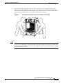
Chassis Lifting Guidelines 2-3
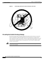
Preventing Electrostatic Discharge Damage
AC-Input and DC-Input Power Guidelines
2-6
2-7
Cisco 7500 Series Installation and Configuration Guide
iv
OL-5008-03 B0
Contents
Cisco 7505 Power Considerations 2-7
Cisco 7507 and Cisco 7507-MX Power Considerations 2-8
Cisco 7513, Cisco 7513-MX, and Cisco 7576 Power Considerations
Plant Wiring Guidelines 2-10
Interference Considerations with Cabling
Distance Limitations of Interface Cabling
2-9
2-10
2-11
Site Environment, Chassis Temperature, and Airflow Guidelines 2-12
Cisco 7505 Airflow Considerations 2-13
Cisco 7507 and Cisco 7507-MX Airflow Considerations 2-14
Cisco 7513, Cisco 7513-MX, and Cisco 7576 Airflow Considerations
2-14
Equipment Rack-Mounting Guidelines 2-15
General Equipment Rack Ventilation Considerations 2-15
Cisco 7505 Rack-Mount Considerations 2-16
Cisco 7507 and Cisco 7507-MX Rack-Mount Considerations 2-18
Cisco 7513, Cisco 7513-MX, and Cisco 7576 Rack-Mount Considerations
2-20
Environmental Monitoring and Reporting Overview for the Cisco 7500 Series 2-22
Cisco 7500 Series Environmental Monitoring 2-23
Cisco 7500 Series Temperature and Voltage Thresholds 2-24
Cisco 7505 Temperature and Voltage Thresholds 2-24
Cisco 7507 and Cisco 7507-MX Temperature and Voltage Thresholds 2-25
Cisco 7513, Cisco 7513-MX, and Cisco 7576 Temperature and Voltage Thresholds
Cisco 7500 Series Environmental Reports 2-26
Cisco 7505 Environmental show Command Examples 2-27
Cisco 7507 and Cisco 7507-MX Environmental show Command Examples 2-29
Cisco 7513 and Cisco 7513-MX Environmental show Command Examples 2-31
Cisco 7576 Environmental show Command Examples 2-35
CHAPTER
3
Installing a Cisco 7500 Series Router
2-25
3-1
Cisco 7500 Series General Installation Considerations
Providing a Ground Connection for the Chassis
3-1
3-2
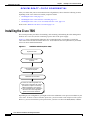
Installing the Cisco 7505 3-4
Cisco 7505 Installation Considerations 3-7
Rack-Mounting the Cisco 7505 3-7
Attaching the Cisco 7505 Cable-Management Brackets 3-9
Connecting Power to the Cisco 7505 DC-Input Power Supply 3-9
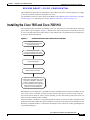
Installing the Cisco 7507 and Cisco 7507-MX 3-11
Cisco 7507 and Cisco 7507-MX Installation Considerations 3-14
Installing Cisco 7507 and Cisco 7507-MX Power Supplies 3-14
Connecting Power to Cisco 7507 or Cisco 7507-MX DC-Input Power Supplies
3-16
Cisco 7500 Series Installation and Configuration Guide
OL-5008-03 B0
v
Contents
Installing the Cisco 7513, Cisco 7513-MX, and Cisco 7576 3-19
Cisco 7513, Cisco 7513-MX, and Cisco 7576 Installation Considerations 3-24
Attaching the Cisco 7513, Cisco 7513-MX, and Cisco 7576 Cable-Management Bracket 3-26
Installing Cisco 7513, Cisco 7513-MX, and Cisco 7576 Power Supplies 3-27
Connecting Power to Cisco 7513, Cisco 7513-MX, and Cisco 7576 DC-Input Power Supplies 3-29
Making Cable Connections to the RSP 3-32
Connecting a Console Terminal to the RSP 3-32
Connecting to the Auxiliary Port 3-32
Using the Y-Cables for Console and Auxiliary Connections
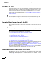
What Do I Do Now?
CHAPTER
4
3-33
3-33
Performing a Basic Configuration of the System
4-1
Starting the System and Observing Initial Conditions
4-2
Overview of Software Configuration Register Settings at Startup
4-3
Configuring the Software Configuration Register 4-4
Configuration Register Bit Meanings 4-5
Changing Configuration Register Settings 4-7
Booting the Cisco 7500 Series Router for the First Time
Using the Enable Secret and the Enable Password
Recovering a Lost Password
4-8
4-8
4-9
Configuring the Cisco 7500 Series System 4-11
Performing a Basic Configuration Using AutoInstall 4-11
Performing a Basic Manual Configuration Using the Setup Facility 4-12
Configuring the Global Parameters 4-12
Configuring Interfaces 4-15
Performing a Basic Configuration Using Configuration Mode 4-18
Checking the Settings 4-19
Saving the Settings to NVRAM and Reviewing Your Configuration 4-19
Implementing Other Configuration Tasks
What Do I Do Now?
4-19
4-20
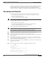
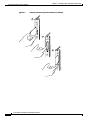
Using the Flash Memory Cards in the RSPs 4-20
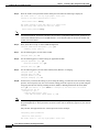
Installing and Removing a Flash Memory Card in an RSP 4-20
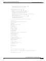
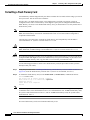
Formatting a Flash Memory Card 4-24
Copying Files to Flash Memory 4-25
Making a Flash Memory Card Image Bootable 4-25
Enabling Booting from Flash Memory 4-26
Additional Commands Associated with Flash Memory 4-26
Additional Procedures Associated with Flash Memory Cards 4-27
Cisco 7500 Series Installation and Configuration Guide
vi
OL-5008-03 B0
Contents
Copying a Bootable Image into a Flash Memory Card 4-27
Copying Bootable Images Between Flash Memory Cards 4-28
Copying Files Between RSP Memory and a Flash Memory Card 4-30
Copying a Configuration File from RSP NVRAM to a Flash Memory Card on the RSP 4-30
Copying a Configuration from RSP DRAM to a Flash Memory Card on the RSP 4-31
Copying a Configuration File from a Flash Memory Card to RSP NVRAM 4-31
Recovering from Locked Blocks in Flash Memory Cards 4-32
If You Need More Configuration Information
CHAPTER
5
Maintaining Your Cisco 7505 Router
4-32
5-1
Tools Required for Maintenance Procedures
5-2
Overview of Maintenance Procedures for the Cisco 7505
5-2
Maintenance Procedures for the Cisco 7505 5-3
Removing and Replacing the Cisco 7505 Cover Panel 5-3
Removing and Replacing the Cisco 7505 Fan Tray 5-5
Removing and Replacing the Cisco 7505 Power Harness Cover 5-7
Removing and Replacing the Cisco 7505 Backplane Cover 5-9
Removing and Replacing the Chassis Interface in the Cisco 7505 5-11
Removing and Replacing the Cisco 7505 Power Supply 5-13
CHAPTER
6
Maintaining Your Cisco 7507 and Cisco 7507-MX Router
Tools Required for Maintenance Procedures
6-1
6-2
Overview of Maintenance Procedures for the Cisco 7507 and Cisco 7507-MX
6-2
Maintenance Procedures for the Cisco 7507 and
Cisco 7507-MX 6-3
Removing Cisco 7507 and Cisco 7507-MX Power Supplies 6-3
Removing and Replacing the Cisco 7507 and Cisco 7507-MX Front Chassis Panels 6-6
Cleaning and Replacing the Cisco 7507 and Cisco 7507-MX Air Filter 6-10
Replacing Cisco 7507 and Cisco 7507-MX Internal Components 6-11
Removing and Replacing the Chassis Interface in the Cisco 7507 and Cisco 7507-MX 6-12
Removing and Replacing the Cisco 7507 and Cisco 7507-MX LED Board 6-13
Removing and Replacing the Cisco 7507 and Cisco 7507-MX Blower Assembly 6-15
CHAPTER
7
Maintaining Your Cisco 7513, Cisco 7513-MX, and Cisco 7576 Router
Tools Required for Maintenance Procedures
7-1
7-2
Maintenance Procedures for the Cisco 7513, Cisco 7513-MX, and Cisco 7576 7-2
Removing Cisco 7513, Cisco 7513-MX, and Cisco 7576 Power Supplies 7-3
Removing and Replacing the Cisco 7513, Cisco 7513-MX, and Cisco 7576 Card Cage Assembly
Removing the Card Cage Assembly 7-5
Cisco 7500 Series Installation and Configuration Guide
OL-5008-03 B0
vii
7-5
Contents
Exchanging the EEPROM Devices 7-7
Installing the Card Cage Assembly 7-9
Removing and Replacing the Cisco 7513, Cisco 7513-MX, and Cisco 7576 Blower Module 7-10
Removing and Replacing the Cisco 7513, Cisco 7513-MX, and Cisco 7576 Chassis Cover Panels 7-11
Removing and Replacing the Cisco 7513, Cisco 7513-MX, and Cisco 7576 Backplane Maintenance
Cover 7-13
Removing and Replacing the Chassis Interface in the Cisco 7513, Cisco 7513-MX, and
Cisco 7576 7-14
CHAPTER
8
Troubleshooting a Cisco 7500 Series Router
Troubleshooting Overview
8-1
8-2
Problem Solving with Cisco 7500 Series Subsystems
8-3
Troubleshooting Guidelines for the Cisco 7505 8-4
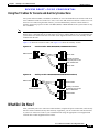
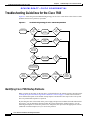
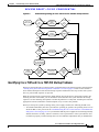
Identifying Cisco 7505 Startup Problems 8-4
Troubleshooting the Cisco 7505 Power Subsystem 8-7
Troubleshooting the Cisco 7505 Cooling Subsystem 8-7
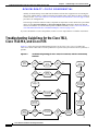
Troubleshooting Guidelines for the Cisco 7507 and
Cisco 7507-MX 8-8
Identifying Cisco 7507 and Cisco 7507-MX Startup Problems 8-9
Troubleshooting the Cisco 7507 and Cisco 7507-MX Power Subsystem 8-10
Troubleshooting the Cisco 7507 and Cisco 7507-MX Cooling Subsystem 8-11
Troubleshooting Guidelines for the Cisco 7513,
Cisco 7513-MX, and Cisco 7576 8-12
Identifying Cisco 7513, Cisco 7513-MX, and Cisco 7576 Startup Problems 8-13
Troubleshooting the Cisco 7513, Cisco 7513-MX, and Cisco 7576 Power Subsystem 8-15
Troubleshooting the Cisco 7513, Cisco 7513-MX, and Cisco 7576 Cooling Subsystem 8-16
Troubleshooting Blower Operation
8-17
Troubleshooting the Cisco 7500 Series Processor Subsystem
Troubleshooting the RSP 8-18
Troubleshooting the Interface Processors 8-19
Using Cisco 7500 Series System LEDs 8-19
Using the Front-Panel System LEDs 8-19
Cisco 7507 and Cisco 7507-MX LEDs 8-20
Cisco 7513, Cisco 7513-MX, and Cisco 7576 LEDs
Using the RSP LEDs 8-21
RSP2 LEDs—Cisco 7500 Series 8-21
RSP4 and RSP8 LEDs—Cisco 7500 Series 8-22
Using the Power Supply LEDs 8-23
Cisco 7505 Power Supply LED 8-23
8-18
8-20
Cisco 7500 Series Installation and Configuration Guide
viii
OL-5008-03 B0
Contents
Cisco 7507 and Cisco 7507-MX Power Supply LEDs 8-23
Cisco 7513, Cisco 7513-MX, and Cisco 7576 Power Supply LEDs
Additional Reference Information for Troubleshooting
CHAPTER
9
Replacing DRAM on the Route Switch Processor
Upgrading or Replacing DRAM SIMMs on the RSP2
Removing RSP2 SIMMs 9-3
Installing New RSP2 SIMMs 9-4
8-26
9-1
9-1
Upgrading or Replacing DRAM DIMMs on the RSP4 and RSP8
Removing RSP4 and RSP8 DIMMs 9-9
Installing New RSP4 or RSP8 DIMMs 9-10
APPENDIX
A
Configuration Register Information
Configuration Bit Meanings
Bits 0–3 A-2
Bit 6 A-3
Bit 7 A-3
Bit 8 A-4
Bit 10 and Bit 14 A-4
Bit 11 and Bit 12 A-4
Bit 13 A-4
Bit 15 A-5
8-25
9-5
A-1
A-1
Displaying the Configuration Register While Running Cisco IOS
A-5
Displaying the Configuration Register While Running ROM Monitor
Setting the Configuration Register While Running Cisco IOS
A-5
A-6
Setting the Configuration Register While Running ROM Monitor
A-6
INDEX
Cisco 7500 Series Installation and Configuration Guide
OL-5008-03 B0
ix
Contents
Cisco 7500 Series Installation and Configuration Guide
x
OL-5008-03 B0
Preface
This preface describes the audience, organization, and conventions of this installation and configuration
guide, and provides information on how to obtain related documentation.
This guide contains specific procedures for the initial hardware installation, and procedures for
performing the basic system configuration of your Cisco 7500 series router. The Cisco 7500 series
includes six routers: the Cisco 7505, Cisco 7507, Cisco 7507-MX, Cisco 7513, Cisco 7513-MX, and
Cisco 7576.
The Cisco 7505, Cisco 7507, and Cisco 7507-MX routers arrive with all processor modules installed;
however, the Cisco 7513, Cisco 7513-MX, and Cisco 7576 routers arrive with processor modules
individually packaged; you need to install these in your system. After you install the hardware and
perform a basic system configuration, you will then use the appropriate software configuration
publications and companion publications to more completely configure your system and its interfaces.
Audience
Setting up and maintaining a network requires the knowledge and expertise of people with a variety of
skills. In many cases, the people responsible for installing hardware and wiring are not the ones who
configure the software and administer the network; therefore, this publication provides information
specific to installing the router hardware and performing a basic system configuration. To use this
publication, you should be familiar with electronic circuitry and wiring practices, and basic network
configuration, and preferably have experience as an electronic or electromechanical technician.
Organization
This guide is organized as follows:
Cisco 7500 Series Installation and Configuration Guide
OL-5008-03 B0
xi
Preface
Related Documentation
Chapter
Title
Description
Chapter 1
Cisco 7500 Series Product
Overview
Describes the physical properties of each of the Cisco
7500 series routers. The remaining sections of this
chapter describe router components, which are
considered to be standard equipment and ship with each
router.
Chapter 2
Preparing for Installation
Describes safety considerations, tools required, an
overview of the installation, and procedures you should
perform before the actual installation of your Cisco 7500
series router.
Chapter 3
Installing a Cisco 7500
Series Router
Provides information for installing the router hardware.
The chapter includes a section describing generic
installation requirements; it also includes additional
sections for each Cisco 7500 series router.
Chapter 4
Performing a Basic
Provides simple procedures for completing a basic
Configuration of the System system configuration of your Cisco 7500 series router,
and for checking and saving this configuration to system
memory.
Chapter 5
Maintaining Your Cisco
7505 Router
Describes the procedures required to perform routine
maintenance and to remove and replace field-replaceable
units (FRUs) in your Cisco 7505 router.
Chapter 6
Maintaining Your Cisco
7507 and Cisco 7507-MX
Router
Describes the procedures required to perform routine
maintenance and to remove and replace field-replaceable
units (FRUs) in your Cisco 7507 and Cisco 7507-MX
router.
Chapter 7
Maintaining Your Cisco
7513, Cisco 7513-MX, and
Cisco 7576 Router
Describes the procedures required to perform routine
maintenance and to remove and replace field-replaceable
units (FRUs) in your Cisco 7513, Cisco 7513-MX, and
Cisco 7576 router.
Chapter 8
Troubleshooting a Cisco
7500 Series Router
Describes basic troubleshooting guidelines, should you
have difficulty with your Cisco 7500 series router
installation.
Chapter 9
Replacing DRAM on the
Route Switch Processor
Describes the procedures required to upgrade the
dynamic random-access memory (DRAM) devices on the
RSPs in your Cisco 7500 series routers.
Appendix A
Configuration Register
Information
Provides configuration register information for the Cisco
7500 Series routers.
Related Documentation
Use the Cisco 7500 Series Routers Documentation Roadmap to access the appropriate installation and
configuration guide for your specific interface processor. Information is available online or on the
Documentation CD-ROM. Use this information in conjunction with the procedures described in Chapter
4, “Performing a Basic Configuration of the System,” to configure the interface processors in your
router.
Cisco 7500 Series Installation and Configuration Guide
xii
OL-5008-03 B0
Preface
Conventions
For comprehensive descriptions and examples of software configuration commands and the procedures
for implementing them, refer to the related software configuration and reference documentation listed in
the “If You Need More Configuration Information” section on page 4-32 and to the Cisco IOS software
release note specific to the release of Cisco IOS software you are running on your system.
For a complete list of related documentation, refer to the Cisco 7500 Series Routers Documentation
Roadmap. Your router also ships with one of the following Quick Start Guides, along with the safety and
compliance documents listed below:
•
Cisco 7505 Router Quick Start Guide (DOC-7812949=)
•
Cisco 7507 Router Quick Start Guide (DOC-7813034=)
•
Cisco 7513 and 7576 Routers Quick Start Guide (DOC-7812954=)
•
Regulatory Compliance and Safety Information for the Cisco 7500 Series Routers(DOC-784194=)
Cisco 7500 series routers include many different field-replacable units (FRUs), such as power supplies,
rack-mount kits, route switch processors, interface processors, versatile inteface processors, port
adapters, and so forth. The documentation flyer includes links to these documents.
Information is available online, on the Documentation CD-ROM, or as printed copies.
Conventions
This document uses the conventions listed in Table 1:
Table 1
Conventions
Convention
Description
boldface font
Commands and keywords are in boldface.
italic font
Arguments for which you supply values are in italics.
[ ]
Elements in square brackets are optional.
{x|y|z}
Alternative keywords are grouped in braces and separated by vertical
bars.
[x|y|z]
Optional alternative keywords are grouped in brackets and separated
by vertical bars.
string
A nonquoted set of characters. Do not use quotation marks around the
string or the string will include the quotation marks.
screen
font
Terminal sessions and information the system displays are in screen
font.
boldface screen
italic screen
font
font
Information you must enter is in boldface
screen
font.
Arguments for which you supply values are in italic
screen
font.
This pointer highlights an important line of text in an
example.
^
The symbol ^ represents the key labeled Control—for example, the
key combination ^D in a screen display means hold down the Control
key while you press the D key.
< >
Nonprinting characters, such as passwords, are in angle brackets.
Notes use the following conventions:
Cisco 7500 Series Installation and Configuration Guide
OL-5008-03 B0
xiii
Preface
Conventions
Note
Means reader take note. Notes contain helpful suggestions or references to material not covered in the
publication.
Timesavers use the following conventions:
Timesaver
Means the described action saves time. You can save time by performing the action described in the
paragraph.
Tips use the following conventions:
Tip
Means the following are useful tips.
Cautions use the following conventions:
Caution
Means reader be careful. In this situation, you might do something that could result in equipment
damage or loss of data.
Warnings use the following conventions:
Warning
Safety warnings appear throughout this publication in procedures that, if performed incorrectly, may
harm you. A warning symbol precedes each warning statement.
Cisco 7500 Series Installation and Configuration Guide
xiv
OL-5008-03 B0
Preface
Safety Warnings
Safety Warnings
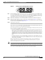
Warning Definition
Warning
IMPORTANT SAFETY INSTRUCTIONS
This warning symbol means danger. You are in a situation that could cause bodily injury. Before you
work on any equipment, be aware of the hazards involved with electrical circuitry and be familiar
with standard practices for preventing accidents. To see translations of the warnings that appear in
this publication, refer to the translated safety warnings that accompanied this device.
Note: SAVE THESE INSTRUCTIONS
Note: This documentation is to be used in conjunction with the specific product installation guide
that shipped with the product. Please refer to the Installation Guide, Configuration Guide, or other
enclosed additional documentation for further details.
Waarschuwing
BELANGRIJKE VEILIGHEIDSINSTRUCTIES
Dit waarschuwingssymbool betekent gevaar. U verkeert in een situatie die lichamelijk letsel kan
veroorzaken. Voordat u aan enige apparatuur gaat werken, dient u zich bewust te zijn van de bij
elektrische schakelingen betrokken risico's en dient u op de hoogte te zijn van de standaard
praktijken om ongelukken te voorkomen. Voor een vertaling van de waarschuwingen die in deze
publicatie verschijnen, dient u de vertaalde veiligheidswaarschuwingen te raadplegen die bij dit
apparaat worden geleverd.
Opmerking BEWAAR DEZE INSTRUCTIES.
Opmerking Deze documentatie dient gebruikt te worden in combinatie met de
installatiehandleiding voor het specifieke product die bij het product wordt geleverd. Raadpleeg de
installatiehandleiding, configuratiehandleiding of andere verdere ingesloten documentatie voor
meer informatie.
Varoitus
TÄRKEITÄ TURVALLISUUTEEN LIITTYVIÄ OHJEITA
Tämä varoitusmerkki merkitsee vaaraa. Olet tilanteessa, joka voi johtaa ruumiinvammaan. Ennen
kuin työskentelet minkään laitteiston parissa, ota selvää sähkökytkentöihin liittyvistä vaaroista ja
tavanomaisista onnettomuuksien ehkäisykeinoista. Tässä asiakirjassa esitettyjen varoitusten
käännökset löydät laitteen mukana toimitetuista ohjeista.
Huomautus SÄILYTÄ NÄMÄ OHJEET
Huomautus Tämä asiakirja on tarkoitettu käytettäväksi yhdessä tuotteen mukana tulleen
asennusoppaan kanssa. Katso lisätietoja asennusoppaasta, kokoonpano-oppaasta ja muista
mukana toimitetuista asiakirjoista.
Cisco 7500 Series Installation and Configuration Guide
OL-5008-03 B0
xv
Preface
Safety Warnings
Attention
IMPORTANTES INFORMATIONS DE SÉCURITÉ
Ce symbole d'avertissement indique un danger. Vous vous trouvez dans une situation pouvant causer
des blessures ou des dommages corporels. Avant de travailler sur un équipement, soyez conscient
des dangers posés par les circuits électriques et familiarisez-vous avec les procédures couramment
utilisées pour éviter les accidents. Pour prendre connaissance des traductions d'avertissements
figurant dans cette publication, consultez les consignes de sécurité traduites qui accompagnent cet
appareil.
Remarque CONSERVEZ CES INFORMATIONS
Remarque Cette documentation doit être utilisée avec le guide spécifique d'installation du produit
qui accompagne ce dernier. Veuillez vous reporter au Guide d'installation, au Guide de
configuration, ou à toute autre documentation jointe pour de plus amples renseignements.
Warnung
WICHTIGE SICHERHEITSANWEISUNGEN
Dieses Warnsymbol bedeutet Gefahr. Sie befinden sich in einer Situation, die zu einer
Körperverletzung führen könnte. Bevor Sie mit der Arbeit an irgendeinem Gerät beginnen, seien Sie
sich der mit elektrischen Stromkreisen verbundenen Gefahren und der Standardpraktiken zur
Vermeidung von Unfällen bewusst. Übersetzungen der in dieser Veröffentlichung enthaltenen
Warnhinweise sind im Lieferumfang des Geräts enthalten.
Hinweis BEWAHREN SIE DIESE SICHERHEITSANWEISUNGEN AUF
Hinweis Dieses Handbuch ist zum Gebrauch in Verbindung mit dem Installationshandbuch für Ihr
Gerät bestimmt, das dem Gerät beiliegt. Entnehmen Sie bitte alle weiteren Informationen dem
Handbuch (Installations- oder Konfigurationshandbuch o. Ä.) für Ihr spezifisches Gerät.
Figyelem!
FONTOS BIZTONSÁGI ELÕÍRÁSOK
Ez a figyelmezetõ jel veszélyre utal. Sérülésveszélyt rejtõ helyzetben van. Mielõtt bármely
berendezésen munkát végezte, legyen figyelemmel az elektromos áramkörök okozta kockázatokra,
és ismerkedjen meg a szokásos balesetvédelmi eljárásokkal. A kiadványban szereplõ
figyelmeztetések fordítása a készülékhez mellékelt biztonsági figyelmeztetések között található.
Megjegyzés ÕRIZZE MEG EZEKET AZ UTASÍTÁSOKAT!
Megjegyzés Ezt a dokumentációt a készülékhez mellékelt üzembe helyezési útmutatóval együtt kell
használni. További tudnivalók a mellékelt Üzembe helyezési útmutatóban (Installation Guide),
Konfigurációs útmutatóban (Configuration Guide) vagy más dokumentumban találhatók.
Avvertenza
IMPORTANTI ISTRUZIONI SULLA SICUREZZA
Questo simbolo di avvertenza indica un pericolo. La situazione potrebbe causare infortuni alle
persone. Prima di intervenire su qualsiasi apparecchiatura, occorre essere al corrente dei pericoli
relativi ai circuiti elettrici e conoscere le procedure standard per la prevenzione di incidenti. Per le
traduzioni delle avvertenze riportate in questo documento, vedere le avvertenze di sicurezza che
accompagnano questo dispositivo.
Nota CONSERVARE QUESTE ISTRUZIONI
Nota La presente documentazione va usata congiuntamente alla guida di installazione specifica
spedita con il prodotto. Per maggiori informazioni, consultare la Guida all'installazione, la Guida
alla configurazione o altra documentazione acclusa.
Cisco 7500 Series Installation and Configuration Guide
xvi
OL-5008-03 B0
Preface
Safety Warnings
Advarsel
VIKTIGE SIKKERHETSINSTRUKSJONER
Dette varselssymbolet betyr fare. Du befinner deg i en situasjon som kan forårsake personskade.
Før du utfører arbeid med utstyret, bør du være oppmerksom på farene som er forbundet med
elektriske kretssystemer, og du bør være kjent med vanlig praksis for å unngå ulykker. For å se
oversettelser av advarslene i denne publikasjonen, se de oversatte sikkerhetsvarslene som følger
med denne enheten.
Merk TA VARE PÅ DISSE INSTRUKSJONENE
Merk Denne dokumentasjonen skal brukes i forbindelse med den spesifikke
installasjonsveiledningen som fulgte med produktet. Vennligst se installasjonsveiledningen,
konfigureringsveiledningen eller annen vedlagt tilleggsdokumentasjon for detaljer.
Aviso
INSTRUÇÕES IMPORTANTES DE SEGURANÇA
Este símbolo de aviso significa perigo. O utilizador encontra-se numa situação que poderá ser
causadora de lesões corporais. Antes de iniciar a utilização de qualquer equipamento, tenha em
atenção os perigos envolvidos no manuseamento de circuitos eléctricos e familiarize-se com as
práticas habituais de prevenção de acidentes. Para ver traduções dos avisos incluídos nesta
publicação, consulte os avisos de segurança traduzidos que acompanham este dispositivo.
Nota GUARDE ESTAS INSTRUÇÕES
Nota Esta documentação destina-se a ser utilizada em conjunto com o manual de instalação
incluído com o produto específico. Consulte o manual de instalação, o manual de configuração ou
outra documentação adicional inclusa, para obter mais informações.
¡Advertencia!
INSTRUCCIONES IMPORTANTES DE SEGURIDAD
Este símbolo de aviso indica peligro. Existe riesgo para su integridad física. Antes de manipular
cualquier equipo, considere los riesgos de la corriente eléctrica y familiarícese con los
procedimientos estándar de prevención de accidentes. Vea las traducciones de las advertencias
que acompañan a este dispositivo.
Nota GUARDE ESTAS INSTRUCCIONES
Nota Esta documentación está pensada para ser utilizada con la guía de instalación del producto
que lo acompaña. Si necesita más detalles, consulte la Guía de instalación, la Guía de
configuración o cualquier documentación adicional adjunta.
Varning!
VIKTIGA SÄKERHETSANVISNINGAR
Denna varningssignal signalerar fara. Du befinner dig i en situation som kan leda till personskada.
Innan du utför arbete på någon utrustning måste du vara medveten om farorna med elkretsar och
känna till vanliga förfaranden för att förebygga olyckor. Se översättningarna av de
varningsmeddelanden som finns i denna publikation, och se de översatta säkerhetsvarningarna som
medföljer denna anordning.
OBS! SPARA DESSA ANVISNINGAR
OBS! Denna dokumentation ska användas i samband med den specifika
produktinstallationshandbok som medföljde produkten. Se installationshandboken,
konfigurationshandboken eller annan bifogad ytterligare dokumentation för närmare detaljer.
Cisco 7500 Series Installation and Configuration Guide
OL-5008-03 B0
xvii
Preface
Safety Warnings
Restricted Area Warning
Warning
This unit is intended for installation in restricted access areas. A restricted access area is where
access can only be gained by service through the use of a special tool, lock and key, or other
means of security, and is controlled by the authority responsible for the location.
Waarschuwing
Dit toestel is bedoeld voor installatie op plaatsen met beperkte toegang. Een plaats met
beperkte toegang is een plaats waar toegang slechts door servicepersoneel verkregen kan
worden door middel van een speciaal instrument, een slot en sleutel, of een ander
veiligheidsmiddel, en welke beheerd wordt door de overheidsinstantie die
verantwoordelijk is voor de locatie.
Cisco 7500 Series Installation and Configuration Guide
xviii
OL-5008-03 B0
Preface
Obtaining Documentation
Varoitus
Tämä laite on tarkoitettu asennettavaksi paikkaan, johon pääsy on rajoitettua. Paikka,
johon pääsy on rajoitettua, tarkoittaa paikkaa, johon vain huoltohenkilöstö pääsee jonkin
erikoistyökalun, lukkoon sopivan avaimen tai jonkin muun turvalaitteen avulla ja joka on
paikasta vastuussa olevien toimivaltaisten henkilöiden valvoma.
Attention
Cet appareil est à installer dans des zones d'accès réservé. Ces dernières sont des zones
auxquelles seul le personnel de service peut accéder en utilisant un outil spécial, un
mécanisme de verrouillage et une clé, ou tout autre moyen de sécurité. L'accès aux zones
de sécurité est sous le contrôle de l'autorité responsable de l'emplacement.
Warnung
Diese Einheit ist zur Installation in Bereichen mit beschränktem Zutritt vorgesehen. Ein
Bereich mit beschränktem Zutritt ist ein Bereich, zu dem nur Wartungspersonal mit einem
Spezialwerkzeugs, Schloß und Schlüssel oder anderer Sicherheitsvorkehrungen Zugang
hat, und der von dem für die Anlage zuständigen Gremium kontrolliert wird.
Avvertenza
Questa unità deve essere installata in un'area ad accesso limitato. Un'area ad accesso
limitato è un'area accessibile solo a personale di assistenza tramite un'attrezzo speciale,
lucchetto, o altri dispositivi di sicurezza, ed è controllata dall'autorità responsabile della
zona.
Advarsel
Denne enheten er laget for installasjon i områder med begrenset adgang. Et område med
begrenset adgang gir kun adgang til servicepersonale som bruker et spesielt verktøy, lås og
nøkkel, eller en annen sikkerhetsanordning, og det kontrolleres av den autoriteten som er
ansvarlig for området.
Aviso
Esta unidade foi concebida para instalação em áreas de acesso restrito. Uma área de
acesso restrito é uma área à qual apenas tem acesso o pessoal de serviço autorizado, que
possua uma ferramenta, chave e fechadura especial, ou qualquer outra forma de segurança.
Esta área é controlada pela autoridade responsável pelo local.
¡Advertencia!
Esta unidad ha sido diseñada para instalarse en áreas de acceso restringido. Área de
acceso restringido significa un área a la que solamente tiene acceso el personal de
servicio mediante la utilización de una herramienta especial, cerradura con llave, o algún
otro medio de seguridad, y que está bajo el control de la autoridad responsable del local.
Varning!
Denna enhet är avsedd för installation i områden med begränsat tillträde. Ett område med
begränsat tillträde får endast tillträdas av servicepersonal med ett speciellt verktyg, lås och
nyckel, eller annan säkerhetsanordning, och kontrolleras av den auktoritet som ansvarar för
området.
Obtaining Documentation
Cisco documentation and additional literature are available on Cisco.com. Cisco also provides several
ways to obtain technical assistance and other technical resources. These sections explain how to obtain
technical information from Cisco Systems.
Cisco 7500 Series Installation and Configuration Guide
OL-5008-03 B0
xix
Preface
Documentation Feedback
Cisco.com
You can access the most current Cisco documentation at this URL:
http://www.cisco.com/univercd/home/home.htm
You can access the Cisco website at this URL:
http://www.cisco.com
You can access international Cisco websites at this URL:
http://www.cisco.com/public/countries_languages.shtml
Ordering Documentation
You can find instructions for ordering documentation at this URL:
http://www.cisco.com/univercd/cc/td/doc/es_inpck/pdi.htm
You can order Cisco documentation in these ways:
•
Registered Cisco.com users (Cisco direct customers) can order Cisco product documentation from
the Ordering tool:
http://www.cisco.com/en/US/partner/ordering/index.shtml
•
Nonregistered Cisco.com users can order documentation through a local account representative by
calling Cisco Systems Corporate Headquarters (California, USA) at 408 526-7208 or, elsewhere in
North America, by calling 800 553-NETS (6387).
Documentation Feedback
You can send comments about technical documentation to [email protected].
You can submit comments by using the response card (if present) behind the front cover of your
document or by writing to the following address:
Cisco Systems
Attn: Customer Document Ordering
170 West Tasman Drive
San Jose, CA 95134-9883
We appreciate your comments.
Obtaining Technical Assistance
For all customers, partners, resellers, and distributors who hold valid Cisco service contracts, Cisco
Technical Support provides 24-hour-a-day, award-winning technical assistance. The Cisco Technical
Support Website on Cisco.com features extensive online support resources. In addition, Cisco Technical
Assistance Center (TAC) engineers provide telephone support. If you do not hold a valid Cisco service
contract, contact your reseller.
Cisco 7500 Series Installation and Configuration Guide
xx
OL-5008-03 B0
Preface
Obtaining Technical Assistance
Cisco Technical Support Website
The Cisco Technical Support Website provides online documents and tools for troubleshooting and
resolving technical issues with Cisco products and technologies. The website is available 24 hours a day,
365 days a year at this URL:
http://www.cisco.com/techsupport
Access to all tools on the Cisco Technical Support Website requires a Cisco.com user ID and password.
If you have a valid service contract but do not have a user ID or password, you can register at this URL:
http://tools.cisco.com/RPF/register/register.do
Submitting a Service Request
Using the online TAC Service Request Tool is the fastest way to open S3 and S4 service requests. (S3
and S4 service requests are those in which your network is minimally impaired or for which you require
product information.) After you describe your situation, the TAC Service Request Tool automatically
provides recommended solutions. If your issue is not resolved using the recommended resources, your
service request will be assigned to a Cisco TAC engineer. The TAC Service Request Tool is located at
this URL:
http://www.cisco.com/techsupport/servicerequest
For S1 or S2 service requests or if you do not have Internet access, contact the Cisco TAC by telephone.
(S1 or S2 service requests are those in which your production network is down or severely degraded.)
Cisco TAC engineers are assigned immediately to S1 and S2 service requests to help keep your business
operations running smoothly.
To open a service request by telephone, use one of the following numbers:
Asia-Pacific: +61 2 8446 7411 (Australia: 1 800 805 227)
EMEA: +32 2 704 55 55
USA: 1 800 553 2447
For a complete list of Cisco TAC contacts, go to this URL:
http://www.cisco.com/techsupport/contacts
Definitions of Service Request Severity
To ensure that all service requests are reported in a standard format, Cisco has established severity
definitions.
Severity 1 (S1)—Your network is “down,” or there is a critical impact to your business operations. You
and Cisco will commit all necessary resources around the clock to resolve the situation.
Severity 2 (S2)—Operation of an existing network is severely degraded, or significant aspects of your
business operation are negatively affected by inadequate performance of Cisco products. You and Cisco
will commit full-time resources during normal business hours to resolve the situation.
Severity 3 (S3)—Operational performance of your network is impaired, but most business operations
remain functional. You and Cisco will commit resources during normal business hours to restore service
to satisfactory levels.
Severity 4 (S4)—You require information or assistance with Cisco product capabilities, installation, or
configuration. There is little or no effect on your business operations.
Cisco 7500 Series Installation and Configuration Guide
OL-5008-03 B0
xxi
Preface
Obtaining Additional Publications and Information
Obtaining Additional Publications and Information
Information about Cisco products, technologies, and network solutions is available from various online
and printed sources.
•
Cisco Marketplace provides a variety of Cisco books, reference guides, and logo merchandise. Visit
Cisco Marketplace, the company store, at this URL:
http://www.cisco.com/go/marketplace/
•
The Cisco Product Catalog describes the networking products offered by Cisco Systems, as well as
ordering and customer support services. Access the Cisco Product Catalog at this URL:
http://cisco.com/univercd/cc/td/doc/pcat/
•
Cisco Press publishes a wide range of general networking, training and certification titles. Both new
and experienced users will benefit from these publications. For current Cisco Press titles and other
information, go to Cisco Press at this URL:
http://www.ciscopress.com
•
Packet magazine is the Cisco Systems technical user magazine for maximizing Internet and
networking investments. Each quarter, Packet delivers coverage of the latest industry trends,
technology breakthroughs, and Cisco products and solutions, as well as network deployment and
troubleshooting tips, configuration examples, customer case studies, certification and training
information, and links to scores of in-depth online resources. You can access Packet magazine at this
URL:
http://www.cisco.com/packet
•
iQ Magazine is the quarterly publication from Cisco Systems designed to help growing companies
learn how they can use technology to increase revenue, streamline their business, and expand
services. The publication identifies the challenges facing these companies and the technologies to
help solve them, using real-world case studies and business strategies to help readers make sound
technology investment decisions. You can access iQ Magazine at this URL:
http://www.cisco.com/go/iqmagazine
•
Internet Protocol Journal is a quarterly journal published by Cisco Systems for engineering
professionals involved in designing, developing, and operating public and private internets and
intranets. You can access the Internet Protocol Journal at this URL:
http://www.cisco.com/ipj
•
World-class networking training is available from Cisco. You can view current offerings at
this URL:
http://www.cisco.com/en/US/learning/index.html
Cisco 7500 Series Installation and Configuration Guide
xxii
OL-5008-03 B0
C H A P T E R
1
Cisco 7500 Series Product Overview
The Cisco 7500 series includes the following routers: Cisco 7505, Cisco 7507, Cisco 7507-MX,
Cisco 7513, Cisco 7513-MX, and Cisco 7576. The Cisco 7500 series routers support multiprotocol,
multimedia routing and bridging with a wide variety of protocols and any combination of ATM, BRI,
channel attachment, channelized E1, T1, and T3, Ethernet, Fast Ethernet, FDDI, HSSI, multichannel,
PRI, Packet over SONET, synchronous serial, Token Ring, and voice media.
The first six sections of this chapter describe the Cisco 7500 series routers, and include the following:
Note
•
Cisco 7505 Overview, page 1-3
•
Cisco 7507 Overview, page 1-6
•
Cisco 7507-MX Overview, page 1-11
•
Cisco 7513 Overview, page 1-15
•
Cisco 7513-MX Overview, page 1-20
•
Cisco 7576 Overview, page 1-25
The Cisco 7513, Cisco 7513-MX, and the Cisco 7576 are similar in appearance. To determine which
router you have, look at the slot numbering label on the back of the unit. The Cisco 7513-MX and
Cisco 7576 are identified as such on the slot numbering label.
The remaining sections of this chapter describe components in the Cisco 7500 series routers, which are
considered to be standard equipment and ship with each router:
•
Route Switch Processor Overview, page 1-31
•
AC-Input and DC-Input Power Supply Overview, page 1-46
•
Arbiter Overview, page 1-50
•
Chassis Interface Overview, page 1-50
•
Fan Tray and Blower Assembly Overview, page 1-51
•
Interface Processor Overview, page 1-54
This section provides a general overview of interface processors; for a complete discussion and
description of all interface processors available for the Cisco 7500 series routers, refer to the
companion publication Interface Processor Installation and Configuration Guide.
•
System Software Overview, page 1-56
Cisco 7500 Series Installation and Configuration Guide
OL-5008-03 B0
1-1
Chapter 1
Cisco 7500 Series Product Overview
Terms and Acronyms
Terms and Acronyms
Following is a list of acronyms, initializations, and terms that identify the Cisco 7500 series system
components and features:
•
AIP—Asynchronous Transfer Mode (ATM) Interface Processor.
•
Backplane—Single or dual system bus to which Cisco interface processors and system processors
attach within a Cisco 7500 series router.
•
Card cage—Assembly in which the backplane is mounted.
•
CIP2—Channel Interface Processor.
•
CT3IP—Channelized T3 Interface Processor.
•
CxBus—Cisco Extended Bus, the 533-megabit-per-second (Mbps) data bus in the Cisco 7000 series
routers.
•
CyBus—Cisco Extended Bus, the 1.067-gigabit-per-second (Gbps) data bus in the Cisco 7500 series
routers; the Cisco 7505 has one CyBus; the Cisco 7507, Cisco 7507-MX, Cisco 7513, and the Cisco
7513-MX have two CyBuses (called the dual CyBus) for an aggregate bandwidth of 2.134 Gbps. The
Cisco 7576 has two dual CyBuses on a single split backplane creating two independent routers. Each
Cisco 7576 independent router has an aggregate bandwidth of 2.134 Gbps. (Interface processors
designed for the CxBus work with the CyBus.)
•
dBus—Diagnostic bus for Route Switch Processor diagnostic and control access, system discovery
and control, microcode download, and fault diagnosis for all processors connected to the CyBus.
•
DIMM—Dual in-line memory module.
•
DRAM—Dynamic random-access memory.
•
EIP—Ethernet Interface Processor.
•
FEIP—Fast Ethernet Interface Processor.
•
FIP—FDDI Interface Processor.
•
FSIP—Fast Serial Interface Processor.
•
FRU—Field-replaceable unit, defined as any spare part that requires replacement by a
Cisco-certified service provider.
•
Gbps—Gigabits per second.
•
HSA—High System Availability.
•
HIP— HSSI Interface Processor.
•
Interface processor—Printed circuit card attached to a metal carrier that provides the electrical
interfaces used by the Cisco 7500 series routers.
•
Mbps—Megabits per second.
•
MIP—MultiChannel Interface Processor.
•
NVRAM—Nonvolatile random-access memory.
•
POSIP—Packet over OC-3 Interface Processor.
•
Processor modules—All interface processors and main system processors used in the Cisco 7500
series routers.
•
RSP—Route Switch Processor; the main system processor. In this publication, the term RSP
includes all RSP models (differences between RSP models are clearly noted).
•
RSP2—Specific main system RSP for the Cisco 7505.
Cisco 7500 Series Installation and Configuration Guide
1-2
OL-5008-03 B0
Chapter 1
Cisco 7500 Series Product Overview
Cisco 7505 Overview
•
RSP4/4+—Specific main system RSP for the Cisco 7507, Cisco 7513, and Cisco 7576.
•
RSP8—Specific main system RSP for the Cisco 7507-MX and Cisco 7513-MX.
•
RSP16—Specific main system RSP for the Cisco 7507, Cisco 7507-MX, and Cisco 7513 and Cisco
7513-MX.
•
SIMM—Single in-line memory module.
•
Spares—Spare parts that do not require replacement by a Cisco-certified service provider.
•
SRAM—Static random-access memory.
•
TDM bus—Connectors on the backplane of the Cisco 7507-MX, Cisco 7513-MX, and Cisco 7576
that are designed for future time-division multiplexing hardware as it becomes available.
•
TRIP—Token Ring Interface Processor.
•
VIP2—Second-Generation Versatile Interface Processor: incorporates interchangeable port and
service adapters for flexible interface functionalities.
•
VIP4/4+—Fourth-Generation Versatile Interface Processor: incorporates the same features as the
VIP2, but with higher distributed switching, increased bandwidth, and features such as high
availability and high service availability, which further reduces system downtime.
•
VIP6-80—The VIP6-80 improves performance over previous versatile interface processors.
Cisco 7505 Overview
The Cisco 7505 supports multiprotocol, multimedia routing and bridging with a wide variety of
protocols and any combination of available electrical interfaces and media. Network interfaces reside on
interface processors that provide a direct connection between the CyBus in your Cisco 7505 and external
networks.
The Cisco 7505 has five slots: four interface processor slots (0 through 3) and one slot for the Route
Switch Processor (RSP2, RSP4/4+, or RSP8). The Cisco 7505 supports 4 VIPs, one for each interface
processor slot. The Cisco 7505 uses a single power supply, with two models available: DC input or
AC input.
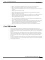
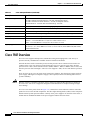
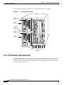
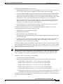
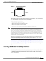
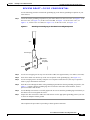
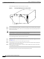
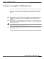
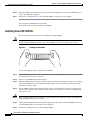
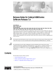
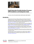
The front, or noninterface processor end, of the Cisco 7505 has a removable panel that is secured with
two captive fasteners. See Figure 1-1. Removing the panel provides access to the internal components:
the power supply and fan tray.
Cisco 7500 Series Installation and Configuration Guide
OL-5008-03 B0
1-3
Chapter 1
Cisco 7500 Series Product Overview
Cisco 7505 Overview
Figure 1-1
Cisco 7505 (Front View)
H2009
Captive fasteners
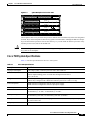
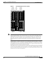
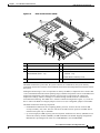
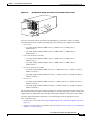
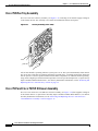
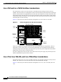
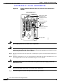
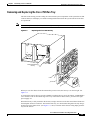
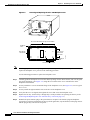
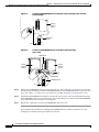
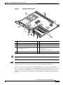
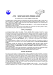
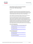
Figure 1-2 shows details of the rear, interface-processor end of the Cisco 7505.
CO
NS
OL
E
AU
X.
HA
LT
RE
SE
T
CP
U
RSP slot
ROUTE SWITCH PROCESSOR
Interface processor slot 3
EN
AB
LE
EN
AB
LE
SL SLO
OT T
0 1
EJ
EC
T
Cisco 7505 (Rear View)
NO
RM
AL
Figure 1-2
Interface processor slot 2
Interface processor slot 1
Interface processor slot 0
H2761
Power switch
Chassis
grounding
receptacles
Power receptacle
DC OK LED
AC-input power supply
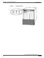
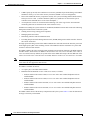
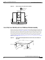
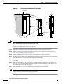
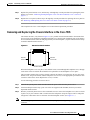
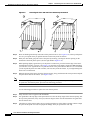
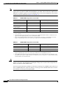
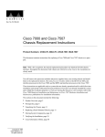
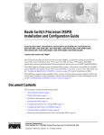
Cisco 7505 CyBus Backplane
The CyBus backplane in the Cisco 7505 provides the physical connections for the RSPs and interface
processors, and transfers information at up to 1.067 Gbps.
The Cisco 7505 CyBus backplane has five slots: interface processor slots 0 through 3, and one slot for
the RSP (RSP2, RSP4/4+, or RSP8), as shown in Figure 1-3.
Cisco 7500 Series Installation and Configuration Guide
1-4
OL-5008-03 B0
Chapter 1
Cisco 7500 Series Product Overview
Cisco 7505 Overview
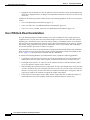
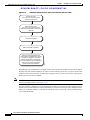
Figure 1-3
CyBus Backplane in the Cisco 7505
SLOT 4
SLOT 3
SLOT 2
SLOT 1
H2875
SLOT 0
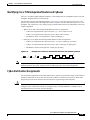
The backplane slots are keyed so that the processor modules can be installed only in the slots designated
for them. Keys on the backplane fit into two key guides on each module. Although the RSP uses unique
keys, all four interface processor slots use the same key, so you can install an interface processor in any
interface processor slot, but not in the RSP slot.
Caution
When installing an RSP, ensure that you are installing it in the appropriate slot to avoid damaging the
key guides or the backplane.
Cisco 7505 System Specifications
Table 1-1 lists the specifications for the Cisco 7505 system.
Table 1-1
Cisco 7505 Specifications
Description
Specification
High-speed backplane
1.067 Gbps CyBus, 4 interface processor slots, and 1 RSP slot
Dimensions (H x W x D)
10.5 x 17.5 x 17.0 in. (26.67 x 44.45 x 43.18 cm)
Chassis depth including power cord and cable management brackets is
19 in. (48.26 cm)
Weight
Chassis only (including power supply and fan array): 46 lb (20.87 kg)
Chassis fully configured with 1 RSP and 4 interface processors: 70 lb (31.75 kg)
Power dissipation
600W maximum configuration with AC-input power supply
600W maximum configuration with DC-input power supply
Heat dissipation
715W (2440 Btu/hr)
Power distribution
75A maximum @ +5 VDC, 15A maximum @ +12 VDC,
3A maximum @ –12 VDC, 5A maximum @ +24 VDC
AC-input rating
100 to 240 VAC, wide input with power factor corrector (PFC);
9A maximum @ 100 VAC, 4A maximum @ 240 VAC (at 600W)
AC-input cable
12 AWG, with 3 leads, an IEC-320 plug on the router end, and a country-dependent plug on
the power source end
Frequency
50 to 60 Hz
Cisco 7500 Series Installation and Configuration Guide
OL-5008-03 B0
1-5
Chapter 1
Cisco 7500 Series Product Overview
Cisco 7507 Overview
Table 1-1
Cisco 7505 Specifications (continued)
Description
Specification
DC-input rating
–40 VDC minimum in North America (–56 VDC in European Union)
–48 VDC nominal in North America (–60 VDC in European Union)
–52 VDC maximum in North America (–72 VDC in European Union)
20A maximum at –48 VDC and 16A maximum @ –60 VDC
DC-input cable
10 AWG, recommended minimum wire gauge (you provide the wire)
DC-input hold-up time
10 ms of output after the DC input has been interrupted
Airflow
Side-to-side through the chassis using a variable-speed, 6-fan array
Temperature
32 to 104°F (0 to 40°C), operating; –4 to 149°F (–20 to 65°C), nonoperating
Humidity
10 to 90%, noncondensing
Software requirement
RSP2 – Cisco IOS Release 10.3(6) or a later release of 10.3
RSP4/4+ – Cisco IOS Release 11.1(8)CA or a later release of 11.1
RSP8 – Cisco IOS Release 12.0(9)S or a later release of 12.0 S
Agency approvals
Safety: UL 1950, CSA 22.2-No. 950, EN60950, EN41003, AUSTEL TS001, AS/NZS 3260,
IEC 801-2, 3, 4, 5, and 6 EMI: FCC Class A, VCCI Class II, and CISPR 22 B (EN 55022)
Conducted Emissions
Cisco 7507 Overview
The Cisco 7507 supports multiprotocol, multimedia routing and bridging with a wide variety of
protocols and any combination of available electrical interfaces and media.
Network interfaces reside on interface processors that provide a direct connection between the two
CyBuses in the Cisco 7507 and your external networks. The Cisco 7507 has seven slots: interface
processor slots 0 and 1, Route Switch Processor (RSP2, RSP4/4+, RSP8, or RSP16) slots 2 and 3, and
interface processor slots 4 through 6. The Cisco 7507 supports 5 VIPs, one for each interface processor
slot.
There are bays for up to two AC-input or DC-input power supplies. The chassis will operate with one
power supply. Although a second power supply is not required, it allows load sharing and increased
system availability.
Caution
Because of agency compliance and safety issues, mixing AC-input and DC-input power supplies in
the same Cisco 7507 is not a supported configuration and should not be attempted. Doing so might
cause damage.
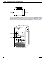
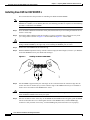
The Cisco 7507 front panel, shown in Figure 1-4, contains three status indicators and two removable
panels for access to the internal components. The three light emitting diodes (LEDs) on the front panel
indicate normal system operation and the currently active power supplies. On the back of the router, a
normal LED on the RSP and LEDs on the power supplies indicate the same status.
Cisco 7500 Series Installation and Configuration Guide
1-6
OL-5008-03 B0
Chapter 1
Cisco 7500 Series Product Overview
Cisco 7507 Overview
Figure 1-4
Cisco 7507 (Front View)
LOWER
POWER
NORMAL
UPPER
POWER
LOWER
POWER
NORMAL
H3135
UPPER
POWER
Cisco 7500 Series Installation and Configuration Guide
OL-5008-03 B0
1-7
Chapter 1
Cisco 7500 Series Product Overview
Cisco 7507 Overview
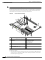
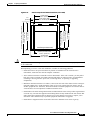
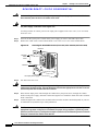
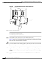
Figure 1-5 shows details on the rear, interface-processor end of the Cisco 7507.
Figure 1-5
Cisco 7507 (Rear View)
Captive
installation screw
DC
FA
IL
AC
PO
WE
R
NO
RM
EN
AB
LE
AL
Upper
power supply
Chassis
grounding
receptacles
EJ
EC
T
SL SLO
OT T
0 1
I
SL MA
AV ST
E ER
O
SL
AV
Captive
installation screw
E/M
CP
RE
AS
U
TE
HA
SE
R
LT
EN
AB
LE
T
H3888
DC
FA
IL
AC
PO
WE
R
Lower
power supply
AU
NS
I
OL
E
ROUTE SWITCH PROCESSOR 2
CO
X.
O
Slot 0
1
2
3
4
5
6
RSP slots
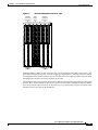
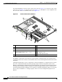
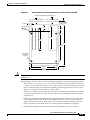
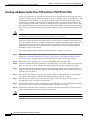
Cisco 7507 Dual CyBus Backplane
The dual CyBus backplane provides the physical connections for the RSPs and interface processors, and
transfers information at up to 2.134 Gbps (1.067 Gbps per CyBus). The dual CyBus has seven slots:
interface processor slots 0 and 1 (CyBus 0), RSP slots 2 and 3, and interface processor slots 4 through 6
(CyBus 1), as shown in Figure 1-6.
Cisco 7500 Series Installation and Configuration Guide
1-8
OL-5008-03 B0
Chapter 1
Cisco 7500 Series Product Overview
Cisco 7507 Overview
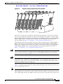
Figure 1-6
Interface
processor
slots 0 and 1
Dual CyBus Backplane in the Cisco 7507
RSP
slots 2
and 3
Interface
processor
slots 4–6
H3886
SLOT 6
SLOT 5
SLOT 4
SLOT 3
SLOT 2
SLOT 1
SLOT 0
CyBus 0
CyBus 1
An RSP2, RSP4/4+, RSP8, or RSP 16 in either slot 2 or slot 3 controls both CyBus 0 and CyBus 1. The
dual CyBus backplane in the Cisco 7507 has an aggregate bandwidth of 2.134 Gbps. The two CyBuses
are independent of one another. Interface processors connected to one CyBus are unaffected by the traffic
generated by the interface processors connected to the other.
The backplane slots are keyed so that the processor modules can be installed only in the slots designated
for them. Keys on the backplane fit into two key guides on each module. Although the RSP uses unique
keys, all five interface processor slots use the same key, so you can install an interface processor in any
interface processor slot, but not in the RSP slot.
Cisco 7500 Series Installation and Configuration Guide
OL-5008-03 B0
1-9
Chapter 1
Cisco 7500 Series Product Overview
Cisco 7507 Overview
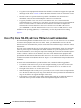
Cisco 7507 System Specifications
Table 1-2 lists the specifications for the Cisco 7507 system.
Table 1-2
Cisco 7507 Specifications
Description
Specification
High-speed backplane
Two 1.0677-Gbps CyBuses, 5 interface processor slots, 2 RSP slots
Dimensions (H x W x D)
19.25 x 17.5 x 25.1 in. (48.90 x 44.45 x 63.75 cm)
Chassis depth including power cord is 28 in. (71.12 cm)
Weight
Chassis only: 76 lb (34.47 kg)
Chassis fully configured, using all slots and 2 power supplies:
145 lb (65.76 kg)
Power supply
700W maximum (for AC-input and DC-input power supplies)
Power dissipation
626W maximum configuration
530W typical with maximum configuration
Heat dissipation
1200W (4100 Btu/hr) with AC-input
300W (1024 Btu/hr) with DC-input
AC-input voltage
100 to 240 VAC, wide input with power factor corrector (PFC)
AC-input cable
12 AWG, with 3 leads, an IEC-320 plug on the router end, and a country-dependent plug on
the power source end
Frequency
50 to 60 Hz autoranging
AC-input ratings
10A maximum @ 100 VAC, 6A maximum @ 240 VAC, chassis fully configured
DC-input ratings
–40 VDC minimum, –48 VDC nominal, –72 VDC maximum
Power distribution
+5.2 VDC @ 95A, +12 VDC @ 15A, –12 VDC @ 5A, +24 VDC @ 4A
DC-input cable
8 AWG, recommended minimum wire gauge (you provide thewire)
Airflow
140 cfm through the system blower
Operating temperature
32 to 104°F (0 to 40°C)
Nonoperating temperature
–4 to 149°F (–20 to 65°C)
Humidity
10 to 90%, noncondensing
Software requirement
RSP2 – Cisco IOS Release 10.3(6) or a later release of 10.3
RSP4/4+ – Cisco IOS Release 11.1(8)CA or a later release of 11.1
RSP8 – Cisco IOS Release 12.0(9)S or a later release of 12.0 S
RSP16 – Cisco IOS Release 12.1(12)E and later and Cisco IOS 12.0(21.02)S and later
Agency approvals
Safety: UL 1950, CSA 22.2-950, EN60950: 1992 EMI: FCC Class A, EN55022 Class B,
VCCI Class 2
Cisco 7500 Series Installation and Configuration Guide
1-10
OL-5008-03 B0
Chapter 1
Cisco 7500 Series Product Overview
Cisco 7507-MX Overview
Cisco 7507-MX Overview
The Cisco 7507-MX supports multiprotocol, multimedia routing and bridging with a wide variety of
protocols and any combination of available electrical interfaces and media.
Network interfaces reside on interface processors that provide a direct connection between the two
CyBuses in the Cisco 7507-MX and your external networks. The Cisco 7507-MX has seven slots:
interface processor slots 0 and 1, Route Switch Processor (RSP2, RSP4/4+, RSP8, or RSP16)
slots 2 and 3, and interface processor slots 4 through 6. The Cisco 7507-MX supports 5 VIPs, one for
each interface processor slot.
There are bays for up to two AC-input or DC-input power supplies. The chassis will operate with one
power supply. Although a second power supply is not required, it allows load sharing and increased
system availability.
Caution
Because of agency compliance and safety issues, mixing AC-input and DC-input power supplies in
the same Cisco 7507-MX is not a supported configuration and should not be attempted. Doing so
might cause damage.
The Cisco 7507-MX front panel, shown in Figure 1-7, contains three status indicators and two removable
panels for access to the internal components. The three light emitting diodes (LEDs) on the front panel
indicate normal system operation and the currently active power supplies. On the back of the router, a
normal LED on the RSP and LEDs on the power supplies indicate the same status.
Figure 1-7
Cisco 7507-MX (Front View)
LOWER
POWER
NORMAL
UPPER
POWER
LOWER
POWER
NORMAL
122302
UPPER
POWER
Cisco 7500 Series Installation and Configuration Guide
OL-5008-03 B0
1-11
Chapter 1
Cisco 7500 Series Product Overview
Cisco 7507-MX Overview
Figure 1-8 shows details on the rear, interface-processor end of the Cisco 7507-MX.
Figure 1-8
Cisco 7507-MX (Rear View)
Captive
installation screw
DC
FA
IL
AC
PO
WE
R
NO
RM
EN
AB
LE
AL
Upper
power supply
Chassis
grounding
receptacles
EJ
EC
T
SL SLO
OT T
0 1
I
SL MA
AV ST
E ER
O
SL
AV
Captive
installation screw
E/M
CP
RE
AS
U
TE
HA
SE
R
LT
EN
AB
LE
T
H3888
DC
FA
IL
AC
PO
WE
R
Lower
power supply
AU
NS
I
OL
E
ROUTE SWITCH PROCESSOR 2
CO
X.
O
Slot 0
1
2
3
4
5
6
RSP slots
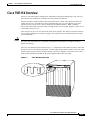
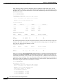
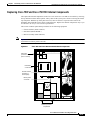
Cisco 7507-MX Dual CyBus Backplane
The dual CyBus backplane provides the physical connections for the RSPs and interface processors, and
transfers information at up to 2.134 Gbps (1.067 Gbps per CyBus). The dual CyBus has seven slots:
interface processor slots 0 and 1 (CyBus 0), RSP slots 2 and 3, and interface processor slots 4 through 6
(CyBus 1), as shown in Figure 1-9.
Cisco 7500 Series Installation and Configuration Guide
1-12
OL-5008-03 B0
Chapter 1
Cisco 7500 Series Product Overview
Cisco 7507-MX Overview
Interface
processor
slots 0 and 1
Interface
processor
slots 4–6
SLOT 6
SLOT 5
SLOT 4
SLOT 3
Note
RSP
slots 2
and 3
SLOT 2
SLOT 1
SLOT 0
CyBus 0
Dual CyBus Backplane in the Cisco 7507-MX
28928
Figure 1-9
CyBus 1
The Cisco 7507-MX backplane includes connectors for time-division multiplexing
(TDM)-compatible hardware. These connectors allow you to connect the Cisco 7507-MX to future
TDM hardware as it becomes available. The Cisco 7507-MX also includes Cisco’s turbo arbiter. The
turbo arbiter, when used in conjunction with other future hardware, significantly increases system
bandwidth. When not used with this future hardware, the turbo arbiter operates in standard CyBus
mode.
An RSP2, RSP4/4+, or RSP8 in either slot 2 or slot 3 controls both CyBus 0 and CyBus 1. The dual
CyBus backplane in the Cisco 7507-MX has an aggregate bandwidth of 2.134 Gbps. The two CyBuses
are independent of one another. Interface processors connected to one CyBus are unaffected by the traffic
generated by the interface processors connected to the other.
The backplane slots are keyed so that the processor modules can be installed only in the slots designated
for them. Keys on the backplane fit into two key guides on each module. Although the RSP uses unique
keys, all five interface processor slots use the same key, so you can install an interface processor in any
interface processor slot, but not in the RSP slot.
Cisco 7500 Series Installation and Configuration Guide
OL-5008-03 B0
1-13
Chapter 1
Cisco 7500 Series Product Overview
Cisco 7507-MX Overview
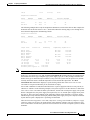
Cisco 7507-MX System Specifications
Table 1-3 lists the specifications for the Cisco 7507-MX system.
Table 1-3
Cisco 7507-MX Specifications
Description
Specification
High-speed backplane
Two 1.0677-Gbps CyBuses, 5 interface processor slots, 2 RSP slots
Dimensions (H x W x D)
19.25 x 17.5 x 25.1 in. (48.90 x 44.45 x 63.75 cm)
Chassis depth including power cord is 28 in. (71.12 cm)
Weight
Chassis only: 76 lb (34.47 kg)
Chassis fully configured, using all slots and 2 power supplies:
145 lb (65.76 kg)
Power supply
700W maximum (for AC-input and DC-input power supplies)
Power dissipation
626W maximum configuration
530W typical with maximum configuration
Heat dissipation
1200W (4100 Btu/hr) with AC-input
300W (1024 Btu/hr) with DC-input
AC-input voltage
100 to 240 VAC, wide input with power factor corrector (PFC)
AC-input cable
12 AWG, with 3 leads, an IEC-320 plug on the router end, and a country-dependent plug
on the power source end
Frequency
50 to 60 Hz autoranging
AC-input ratings
10A maximum @ 100 VAC, 6A maximum @ 240 VAC, chassis fully configured
DC-input ratings
–40 VDC minimum, –48 VDC nominal, –72 VDC maximum
Power distribution
+5.2 VDC @ 95A, +12 VDC @ 15A, –12 VDC @ 5A, +24 VDC @ 4A
DC-input cable
8 AWG, recommended minimum wire gauge (you provide the wire)
Airflow
140 cfm through the system blower
Operating temperature
32 to 104°F (0 to 40°C)
Nonoperating temperature
–4 to 149°F (–20 to 65°C)
Humidity
10 to 90%, noncondensing
Software requirement
RSP2 – Cisco IOS Release 10.3(6) or a later release of 10.3
RSP4/4+ – Cisco IOS Release 11.1(8)CA or a later release of 11.1
RSP8 – Cisco IOS Release 12.0(9)S or a later release of 12.0 S
RSP16 – Cisco IOS Release 12.1(12)E and later and Cisco IOS 12.0(21.02)S and later
Agency approvals
Safety: UL 1950, CSA 22.2-950, EN60950: 1992 EMI: FCC Class A, EN55022 Class B,
VCCI Class 2
Cisco 7500 Series Installation and Configuration Guide
1-14
OL-5008-03 B0
Chapter 1
Cisco 7500 Series Product Overview
Cisco 7513 Overview
Cisco 7513 Overview
The Cisco 7513 router supports multiprotocol, multimedia routing and bridging with a wide variety of
protocols and any combination of available electrical interfaces and media. Network interfaces reside on
interface processors that provide a direct connection between the two CyBuses in the Cisco 7513 and
your external networks. The Cisco 7513 has 13 slots: interface processor slots 0 through 5, Route Switch
Processor (RSP2, RSP4/4+, RSP8, or RSP16) slots 6 and 7, and interface processor slots 8 through 12.
The Cisco 7513 supports 11 VIPs, one for each interface processor slot.
There are bays for up to two AC-input or DC-input power supplies. The chassis will operate with one
power supply. Although a second power supply is not required, it allows load sharing and increased
system availability.
Caution
Because of agency compliance and safety issues, mixing AC-input and DC-input power supplies in the
same Cisco 7513 is not a supported configuration and should not be attempted. Doing so might cause
damage.
The Cisco 7513 is shown in Figure 1-10. The three front-panel LEDs indicate system and power supply
status, and LEDs on the RSP, interface processors, and power supplies indicate status.
Cisco 7500 Series Installation and Configuration Guide
OL-5008-03 B0
1-15
Chapter 1
Cisco 7500 Series Product Overview
Cisco 7513 Overview
Figure 1-10
POWER
A
POWER
B
NORMAL
122303
Front-panel
LEDs
Cisco 7513 (Front View)
Cisco 7500 Series Installation and Configuration Guide
1-16
OL-5008-03 B0
Chapter 1
Cisco 7500 Series Product Overview
Cisco 7513 Overview
Figure 1-11 shows details on the rear, interface-processor end of the Cisco 7513.
Figure 1-11
Cisco 7513 (Rear View)
Blower module
Cable-management
bracket
NO
RM
AL
EN
EJE
AB
LE
AB
LE
CT
SLO SLO
T0 T1
SLA MA
S
V E TE
R
Card cage and
processor modules
SLA
VE
/M
CP
RE
AU
NS
TE
HA
R
LT
EN
T
X.
ROUTE SWITCH PROCESSOR 2
CO
AS
U
SE
OLE
Air intake vent
AC
OK
FAN
OK
OUTPUT
FAIL
AC
OK
OUTPUT
FAIL
POWER
A
POWER
B
Chassis grounding
receptacles
I
122373
Power supplies
FAN
OK
I
0
0
Cisco 7513 Dual CyBus Backplane
The dual CyBus backplane, located at the rear of the Cisco 7513 removable card cage, provides the
physical connections for the RSPs and interface processors, and transfers information at up to
2.134 Gbps (1.067 Gbps per CyBus).
The dual CyBus has 13 slots: interface processor slots 0 through 5 (CyBus 0); two RSP slots (slots
6 and 7); interface processor slots 8 through 12 (CyBus 1), as shown in Figure 1-12.
Cisco 7500 Series Installation and Configuration Guide
OL-5008-03 B0
1-17
Chapter 1
Cisco 7500 Series Product Overview
Cisco 7513 Overview
Dual CyBus Backplane in the Cisco 7513
H3163
Figure 1-12
0
1
2
3
4
CyBus 0 (slots 0 through 5)
5
RSP RSP
8
9
10
11
12
CyBus 1 (slots 8 through 12)
An RSP2, RSP4/4+, or RSP8 in either slot 6 or slot 7 controls both CyBus 0 and CyBus 1. The dual
CyBus backplane in the Cisco 7513 has an aggregate bandwidth of 2.134 Gbps. Interface processors
connected to one CyBus are unaffected by the traffic generated by the interface processors connected to
the other CyBus. The two CyBuses are independent of one another.
The backplane slots are keyed so that the processor modules can be installed only in the slots designated
for them. Keys on the backplane fit into two key guides on each module. Although the RSP uses unique
keys, all eleven interface processor slots use the same key, so you can install an interface processor in
any interface processor slot, but not in the RSP slot.
Note
A spare card cage assembly ships as Product Number MAS-7513CDCAGE=. For maintenance
information about the card cage assembly, see the “Removing and Replacing the Cisco 7513, Cisco
7513-MX, and Cisco 7576 Card Cage Assembly” section on page 7-5.
Cisco 7500 Series Installation and Configuration Guide
1-18
OL-5008-03 B0
Chapter 1
Cisco 7500 Series Product Overview
Cisco 7513 Overview
Cisco 7513 System Specifications
Table 1-4 lists the specifications for the Cisco 7513 system.
Table 1-4
Cisco 7513 Specifications
Backplane
Two 1.0677-Gbps CyBuses, 11 interface processor slots, 2 RSP slots
Dimensions
(H x W x D)
33.75 x 17.5 x 22 in. (85.73 x 44.45 x 55.88 cm)
Chassis width including rack-mount flanges is 18.93 in. (48.1 cm)
Chassis depth including power cables and cable-management bracket: 24 in. (60.96 cm)
Weight
Chassis with blower module: 75 lb (34.02 kg)
Chassis with blower module and 1 power supply: 100 lb (45.36 kg)
Chassis with blower module and 2 power supplies: 125 lb (56.7 kg)
Chassis with blower module, 2 power supplies, and all slots filled: ~160 lb (72.58 kg),
each processor module weighs ~2.5 lb (1.13 kg)
Power dissipation
1600W with a maximum configuration and 1 AC-input power supply
1600W with a maximum configuration and 1 DC-input power supply
1700W nominal with a maximum configuration and either 2 AC-input or 2 DC-input power
supplies
Heat dissipation
1600W (5461 Btu/hr)
AC-input voltage
100 to 240 VAC
Frequency
50/60 Hz
AC-input cable
1
12 AWG, with 3 leads, an IEC-320 plug on the router end, and a country-dependent plug on the
power source end
AC-input voltage
and current
100 VAC at 16 amps (A) maximum, wide input with power factor corrector (PFC)
240 VAC at 7A maximum
DC-input voltage
and current
–48 VDC nominal at 35A in North America
(–60 VDC at 35A in the European Union)
DC-input cable
8 AWG (recommended minimum), with 3 leads and rated for at least 194°F (90°C) (you supply
the cable)
Power distribution
+5.2 VDC @ 75A, +12 VDC @ 15A, –12 VDC @ 3A, +24 VDC @ 5A
Airflow/noise level
Bottom to top through chassis by variable-speed blower (62 to 70 dBA)
Temperature
32 to 104°F (0 to 40°C), operating; –4 to 149°F (–20 to 65°C), nonoperating
Relative humidity
10 to 90%, noncondensing
Software requirement
RSP2 – Cisco IOS Release 10.3(6) or a later release of 10.3
RSP4/4+ – Cisco IOS Release 11.1(8)CA or a later release of 11.1
RSP8 – Cisco IOS Release 12.0(9)S or a later release of 12.0 S
RSP16 – Cisco IOS Release 12.1(12)E and later and Cisco IOS 12.0(21.02)S and later
Agency approvals
Safety: UL 1950, CSA 22.2-950, EN60950, EN41003, TS001, AS/NZS 3260
EMI: FCC Class A, EN60555-2, EN55022 Class B, VDE 0878 Part 3, 30 Class B Immunity:
EN55101/2 (ESD), EN55101/3 (RFI), EN55101/4 (Burst), EN55101/5 (Surge), EN55101/6
(Conducted), IEC77B (AC Disturbance)
1. The Cisco 7513 requires a minimum of 20A service with a 20A receptacle at the power source. The power cable supplied with the Cisco 7513 uses a 20A
male plug.
Cisco 7500 Series Installation and Configuration Guide
OL-5008-03 B0
1-19
Chapter 1
Cisco 7500 Series Product Overview
Cisco 7513-MX Overview
Cisco 7513-MX Overview
The Cisco 7513-MX router supports multiprotocol, multimedia routing and bridging with a wide variety
of protocols and any combination of available electrical interfaces and media. Network interfaces reside
on interface processors that provide a direct connection between the two CyBuses in the Cisco 7513-MX
and your external networks. The Cisco 7513-MX has 13 slots: interface processor slots 0 through 5,
Route Switch Processor (RSP2, RSP4/4+, RSP8, or RSP16) slots 6 and 7, and interface processor slots
8 through 12. The Cisco 7513-MX supports 11 VIPs, one for each interface processor slot.
There are bays for up to two AC-input or DC-input power supplies. The chassis will operate with one
power supply. Although a second power supply is not required, it allows load sharing and increased
system availability.
Caution
Because of agency compliance and safety issues, mixing AC-input and DC-input power supplies in the
same Cisco 7513-MX is not a supported configuration and should not be attempted. Doing so might
cause damage.
The Cisco 7513-MX is shown in Figure 1-13. The three front-panel LEDs indicate system and power
supply status, and LEDs on the RSP, interface processors, and power supplies indicate status.
Cisco 7500 Series Installation and Configuration Guide
1-20
OL-5008-03 B0
Chapter 1
Cisco 7500 Series Product Overview
Cisco 7513-MX Overview
Figure 1-13
POWER
A
POWER
B
NORMAL
122303
Front-panel
LEDs
Cisco 7513-MX (Front View)
Cisco 7500 Series Installation and Configuration Guide
OL-5008-03 B0
1-21
Chapter 1
Cisco 7500 Series Product Overview
Cisco 7513-MX Overview
Figure 1-14 shows details on the rear, interface-processor end of the Cisco 7513-MX.
Figure 1-14
Cisco 7513-MX (Rear View)
Blower module
Cable-management
bracket
NO
RM
AL
EN
EJE
AB
LE
AB
LE
CT
SLO SLO
T0 T1
SLA MA
S
V E TE
R
Card cage and
processor modules
SLA
VE
/M
CP
RE
AU
NS
TE
HA
R
LT
EN
T
X.
ROUTE SWITCH PROCESSOR 2
CO
AS
U
SE
OLE
Air intake vent
AC
OK
FAN
OK
OUTPUT
FAIL
AC
OK
OUTPUT
FAIL
POWER
A
POWER
B
Chassis grounding
receptacles
I
122374
Power supplies
FAN
OK
I
0
0
Cisco 7513-MX Dual CyBus Backplane
The dual CyBus backplane, located at the rear of the Cisco 7513-MX removable card cage, provides the
physical connections for the RSPs and interface processors, and transfers information at up to
2.134 Gbps (1.067 Gbps per CyBus).
The dual CyBus has 13 slots: interface processor slots 0 through 5 (CyBus 0); two RSP slots (slots
6 and 7); interface processor slots 8 through 12 (CyBus 1), as shown in Figure 1-15.
Cisco 7500 Series Installation and Configuration Guide
1-22
OL-5008-03 B0
Chapter 1
Cisco 7500 Series Product Overview
Cisco 7513-MX Overview
Dual CyBus Backplane in the Cisco 7513-MX
28929
Figure 1-15
0
1
2
3
4
CyBus 0 (slots 0 through 5)
Note
5
RSP RSP
8
9
10
11
12
CyBus 1 (slots 8 through 12)
The Cisco 7513-MX backplane includes connectors for time-division multiplexing (TDM)-compatible
hardware. These connectors allow you to connect the Cisco 7513-MX to future TDM hardware as it
becomes available. The Cisco 7513-MX also includes the Cisco turbo arbiter. The turbo arbiter, when
used in conjunction with other future hardware, significantly increases system bandwidth. When not
used with this future hardware, the turbo arbiter operates in standard CyBus mode.
An RSP2, RSP4/4+, or RSP8 in either slot 6 or slot 7 controls both CyBus 0 and CyBus 1. The dual
CyBus backplane in the Cisco 7513-MX has an aggregate bandwidth of 2.134 Gbps. Interface processors
connected to one CyBus are unaffected by the traffic generated by the interface processors connected to
the other CyBus. The two CyBuses are independent of one another.
The backplane slots are keyed so that the processor modules can be installed only in the slots designated
for them. Keys on the backplane fit into two key guides on each module. Although the RSP uses unique
keys, all eleven interface processor slots use the same key, so you can install an interface processor in
any interface processor slot, but not in the RSP slot.
Note
A spare card cage assembly ships as Product Number MAS-7513MX-CDCAGE=. For maintenance
information about the card cage assembly, see the “Removing and Replacing the Cisco 7513, Cisco
7513-MX, and Cisco 7576 Card Cage Assembly” section on page 7-5.
Cisco 7500 Series Installation and Configuration Guide
OL-5008-03 B0
1-23
Chapter 1
Cisco 7500 Series Product Overview
Cisco 7513-MX Overview
Cisco 7513-MX System Specifications
Table 1-5 lists the specifications for the Cisco 7513-MX system.
Table 1-5
Cisco 7513-MX Specifications
Description
Specification
Backplane
Two 1.0677-Gbps CyBuses: 11 interface processor slots, 2 RSP slots
Dimensions
(H x W x D)
33.75 x 17.5 x 22 in. (85.73 x 44.45 x 55.88 cm)
Chassis width including rack-mount flanges is 18.93 in. (48.1 cm)
Chassis depth including power cables and cable-management bracket is 24 in. (60.96 cm)
Weight
Chassis with blower module: 75 lb (34.02 kg)
Chassis with blower module and 1 power supply: 100 lb (45.36 kg)
Chassis with blower module and 2 power supplies: 125 lb (56.7 kg)
Chassis with blower module, 2 power supplies, and all slots filled: ~160 lb (72.58 kg),
each processor module weighs ~2.5 lb (1.13 kg)
Power dissipation
1600W with a maximum configuration and 1 AC-input power supply
1600W with a maximum configuration and 1 DC-input power supply
1700W nominal with a maximum configuration and either 2 AC-input or 2 DC-input power
supplies
Heat dissipation
1600W (5461 Btu/hr)
AC-input voltage
100 to 240 VAC
Frequency
50/60 Hz
AC-input cable
1
12 AWG, with 3 leads, an IEC-320 plug on the router end, and a country-dependent plug on the
power source end
AC-input voltage
and current
100 VAC at 16 amps (A) maximum, wide input with power factor corrector (PFC)
240 VAC at 7A maximum
DC-input voltage
and current
–48 VDC nominal at 35A in North America (–60 VDC at 35A in the European Union)
DC-input cable
8 AWG (recommended minimum), with 3 leads and rated for at least 194°F (90°C) (you supply the
cable)
Power distribution
+5.2 VDC @ 75A, +12 VDC @ 15A, –12 VDC @ 3A, +24 VDC @ 5A
Airflow/noise level
Bottom to top through chassis by variable-speed blower (62 to 70 dBA)
Temperature
32 to 104°F (0 to 40°C), operating; –4 to 149°F (–20 to 65°C), nonoperating
Relative humidity
10 to 90%, noncondensing
Software requirement
RSP2 – Cisco IOS Release 10.3(6) or a later release of 10.3
RSP4/4+ – Cisco IOS Release 11.1(8)CA or a later release of 11.1
RSP8 – Cisco IOS Release 12.0(9)S or a later release of 12.0 S
RSP16 – Cisco IOS Release 12.1(12)E and later and Cisco IOS 12.0(21.02)S and later
Agency approvals
Safety: UL 1950, CSA 22.2-950, EN60950, EN41003, TS001, AS/NZS 3260
EMI: FCC Class A, EN60555-2, EN55022 Class B, VDE 0878 Part 3, 30 Class B
Immunity: EN55101/2 (ESD), EN55101/3 (RFI), EN55101/4 (Burst), EN55101/5 (Surge),
EN55101/6 (Conducted), IEC77B (AC Disturbance)
1. The Cisco 7513-MX requires a minimum of 20A service with a 20A receptacle at the power source. The power cable supplied with the Cisco 7513-MX
uses a 20A male plug.
Cisco 7500 Series Installation and Configuration Guide
1-24
OL-5008-03 B0
Chapter 1
Cisco 7500 Series Product Overview
Cisco 7576 Overview
Cisco 7576 Overview
The Cisco 7576 router supports multiprotocol, multimedia routing and bridging with a wide variety of
protocols and any combination of available electrical interfaces and media. The Cisco 7576 consists of
two independent Cisco 7500 series routers configured on a single split backplane. This system is housed
within the chassis footprint of a Cisco 7513 router.
Network interfaces reside on interface processors that provide a direct connection between the two
independent dual CyBuses located on the backplane of the Cisco 7576 and your external networks. The
two independent dual CyBuses facilitate the configuration of two independent routers on a single
backplane. These routers are identified as router A and router B.
The backplane of the Cisco 7576 has 13 slots. Router A uses interface processor slots 0 through 5 with
a Route Switch Processor (RSP4/4+ or RSP8) in slot 6. Router B uses interface processor slots 8 through
12 with a Route Switch Processor (RSP4/4+ or RSP8) in slot 7. The Cisco 7576 supports 10 VIPs, one
for each interface processor slot; 6 VIPs are supported in Router A and 5 VIPs are supported in Router B.
There are bays for up to two AC-input or DC-input power supplies. The chassis will operate with one
power supply. Although a second power supply is not required, it allows load sharing and increased
system availability.
Caution
Note
Because of agency compliance and safety issues, mixing AC-input and DC-input power supplies in the
same Cisco 7576 is not a supported configuration and should not be attempted. Doing so might cause
damage.
The Cisco 7576 is sold as a new unit and as an upgrade kit to the Cisco 7513. When purchased new,
the Cisco 7576 comes standard with two AC-input power supplies and two RSP4/4+s. The
Cisco 7576 upgrade kit includes only the system chassis, which includes the card cage and
backplane. The upgrade kit does not include power supplies, RSPs, or interface processors. These
parts are exchanged with the parts from the Cisco 7513 unit that is being upgraded. If you purchased
a Cisco 7576 upgrade kit, refer to the document Cisco 7513 and Cisco 7576 Chassis Replacement
and Upgrade Instructions.
Figure 1-16 shows the front view of the Cisco 7576. The three front-panel LEDs indicate system and
power supply status, and LEDs on the RSP, interface processors, and power supplies indicate status.
Cisco 7500 Series Installation and Configuration Guide
OL-5008-03 B0
1-25
Chapter 1
Cisco 7500 Series Product Overview
Cisco 7576 Overview
Figure 1-16
POWER
A
POWER
B
NORMAL
122303
Front-panel
LEDs
Cisco 7576 (Front View)
Cisco 7500 Series Installation and Configuration Guide
1-26
OL-5008-03 B0
Chapter 1
Cisco 7500 Series Product Overview
Cisco 7576 Overview
Figure 1-17 shows details on the rear, interface-processor end of the Cisco 7576.
Figure 1-17
Cisco 7576 (Rear View)
Blower module
Cable-management
bracket
NO
RM
NO
AL
RM
AL
EN
EJE
Card cage and
processor modules
SLO SLO
T0 T1
SLA MA
S
VE TE
R
SLA MA
S
VE TE
R
VE
SLA
/M
CP
RE
AU
SE
/M
CP
RE
T
AU
X.
OLE
VE
R
LT
CO
NS
AS
U
TE
HA
SE
AB
LE
R
LT
EN
T
X.
OLE
ROUTE SWITCH PROCESSOR 2
NS
TE
HA
ROUTE SWITCH PROCESSOR 2
Interface processor
slot numbering
scheme
AS
U
LE
CT
SLO SLO
T0 T1
SLA
CO
EJE
CT
AB
Air intake vent
AC
OK
FAN
OK
OUTPUT
FAIL
AC
OK
OUTPUT
FAIL
POWER
A
POWER
B
Chassis grounding
receptacles
Note
14868
Power supplies
FAN
OK
I
I
0
0
The Cisco 7513 and Cisco 7576 use the same chassis, power supplies, cover panels, and accessories.
Externally, the two models appear the same. However the backplane and interface processor slot
numbering scheme are different. See Figure 1-19 for an enlarged view of the Cisco 7576 interface
processor slot numbering scheme. This area visually identifies which router model you have.
Cisco 7576 Dual CyBus Backplane
The Cisco 7576 features two dual CyBuses, creating two independent routers on one split backplane.
The dual CyBus backplane, located at the rear of the removable card cage, provides the physical
connections for the RSPs and interface processors, and transfers information at up to 2.134 Gbps (1.067
Gbps per CyBus) per router.
Cisco 7500 Series Installation and Configuration Guide
OL-5008-03 B0
1-27
Chapter 1
Cisco 7500 Series Product Overview
Cisco 7576 Overview
An RSP4/4+ or RSP8 in slot 6 controls router A and both CyBus 0 and CyBus 1. An RSP4/4+ or RSP8
in slot 7 controls router B and both CyBus 2 and CyBus 3. The dual CyBus backplane in the Cisco 7576
has an aggregate bandwidth of 2.134 Gbps per router. Interface processors connected to the set of
CyBuses on router A are unaffected by the traffic generated by the interface processors connected to the
set of CyBuses on router B. The dual CyBuses assigned to router A are independent of the dual CyBuses
assigned to router B.
Figure 1-18 shows the details of the dual CyBus backplane.
Cisco 7576 Dual CyBus Backplane
14867
Figure 1-18
0
1
2
3
4
5
Slots 2 and 4 = CyBus 1
Slots 0, 1, 3, and 5 = CyBus 0
Router A
Note
RSP RSP
A
B
8
9
10
11
12
Slots 9 and 11 = CyBus 3
Slots 8, 10, and 12 = CyBus 2
Router B
The Cisco 7576 backplane includes connectors for time-division multiplexing (TDM)-compatible
hardware. These connectors allow you to connect the Cisco 7576 to future TDM hardware as it
becomes available.
The backplane slots are keyed so that the processor modules can be installed only in the slots designated
for them. Keys on the backplane fit into two key guides on each module. Although the RSP uses unique
keys, all 11 interface processor slots use the same key, so you can install an interface processor in any
interface processor slot, but not in the RSP slot.
For maintenance information about the card cage assembly, see the “Removing and Replacing the Cisco
7513, Cisco 7513-MX, and Cisco 7576 Card Cage Assembly” section on page 7-5.
Cisco 7500 Series Installation and Configuration Guide
1-28
OL-5008-03 B0
Chapter 1
Cisco 7500 Series Product Overview
Cisco 7576 Overview
Identifying Cisco 7576 Independent Routers and CyBuses
The Cisco 7576 dual CyBus backplane includes 13 slots and provides two independent routers on a split
backplane, designated router A and router B.
The interface processor slot numbering scheme (see Figure 1-19) on the card cage of the Cisco 7576
provides easy identification of the independent routers, CyBuses, and slots that make up the Cisco 7576
backplane. The scheme uses color coding to help you differentiate between the independent router and
CyBus assignments.
•
White text on dark-colored backgrounds identifies router A components:
– CyBus 0 is assigned interface processor slots 0, 1, 3, and 5 (white on red).
– CyBus 1 is assigned interface processor slots 2 and 4 (white on blue).
– The RSP for router A is assigned slot 6 (white on dark gray).
•
Dark gray text on light-colored backgrounds identifies router B components:
– CyBus 2 is assigned interface processor slots 8, 10, and 12 (dark gray on yellow).
– CyBus 3 is assigned interface processor slots 9 and 11 (dark gray on light green).
– The RSP for router B is assigned slot 7 (dark gray on white).
3
Enlarged View of the Cisco 7576 Interface Processor Slot Numbering Scheme
4
5
7576 ROUTER A
Note
6
7
RSP
RSP
8
9
10
14846
Figure 1-19
7576 ROUTER B
To provide a viewable image, slot numbers 0, 1, 2, 11, and 12 are not shown in Figure 1-19. The slot
numbering scheme uses color coding to assist in identifying routers and CyBus assignments.
CyBus Slot Number Assignments
The slot number assignments of the independent router CyBuses are separated by design. This facilitates
automatic distribution of the system load across the CyBuses as interface processors are added. This
design also provides better electrical flow and improves signal timing on the backplane.
Caution
If you are only configuring one of the two routers that make up the Cisco 7576, make sure to
configure router A instead of router B. To configure router A, install an RSP4/4+ or RSP8 in slot 6,
and install interface processors in slots 0 through 5.
Cisco 7500 Series Installation and Configuration Guide
OL-5008-03 B0
1-29
Chapter 1
Cisco 7500 Series Product Overview
Cisco 7576 Overview
Cisco 7576 System Specifications
Table 1-6 lists the specifications for the Cisco 7576 system.
Table 1-6
Cisco 7576 Specifications
Description
Specification
Backplane
Four 1.0677-Gbps CyBuses divided into sets of 2 creating 2 independent routers: 6 interface
processor slots and 1 RSP slot designated as router A, and 5 interface processor slots and 1 RSP
slot designated as router B
Dimensions
(H x W x D)
33.75 x 17.5 x 22 in. (85.73 x 44.45 x 55.88 cm)
Chassis width including rack-mount flanges is 18.93 in. (48.1 cm)
Chassis depth including power cables and cable-management bracket is 24 in. (60.96 cm)
Weight
Chassis with blower module: 75 lb (34.02 kg)
Chassis with blower module and 1 power supply: 100 lb (45.36 kg)
Chassis with blower module and 2 power supplies: 125 lb (56.7 kg)
Chassis with blower module, 2 power supplies, and all slots filled: ~160 lb (72.58 kg),
each processor module weighs ~2.5 lb (1.13 kg)
Power dissipation
1600W with a maximum configuration and 1 AC-input power supply
1600W with a maximum configuration and 1 DC-input power supply
1700W nominal with a maximum configuration and either 2 AC-input or 2 DC-input power
supplies
Heat dissipation
1600W (5461 Btu/hr)
AC-input voltage
100 to 240 VAC
Frequency
50/60 Hz
AC-input cable
1
12 AWG, with 3 leads, an IEC-320 plug on the router end, and a country-dependent plug on the
power source end
AC-input voltage
and current
100 VAC at 16 amps (A) maximum, wide input with power factor correction (PFC)
240 VAC at 7A maximum
DC-input voltage
and current
–48 VDC nominal at 35A in North America
(–60 VDC at 35A in the European Union)
DC-input cable
8 AWG (recommended minimum), with 3 leads and rated for at least 194°F (90°C) (you supply
the cable)
Power distribution
+5.2 VDC @ 75A, +12 VDC @ 15A, –12 VDC @ 3A, +24 VDC @ 5A
Airflow/noise level
Bottom to top through chassis by variable-speed blower (62 to 70 dBA)
Temperature
32 to 104°F (0 to 40°C), operating; –4 to 149°F (–20 to 65°C), nonoperating
Relative humidity
10 to 90%, noncondensing
Software requirement
RSP4/4+ – Cisco IOS Release 11.1(22)CC, or a later release of 11.1
RSP8 – Cisco IOS Release 12.0(9)S or a later release of 12.0 S
Agency approvals
Safety: UL 1950, CSA 22.2-950, EN60950, EN41003, TS001, AS/NZS 3260
EMI: FCC Class A, EN60555-2, EN55022 Class B, VDE 0878 Part 3, 30 Class B Immunity:
EN55101/2 (ESD), EN55101/3 (RFI), EN55101/4 (Burst), EN55101/5 (Surge), EN55101/6
(Conducted), IEC77B (AC Disturbance)
1. The Cisco 7576 requires a minimum of 20A service with a 20A receptacle at the power source. The power cable supplied with the Cisco 7576 uses a 20A
male plug.
Cisco 7500 Series Installation and Configuration Guide
1-30
OL-5008-03 B0
Chapter 1
Cisco 7500 Series Product Overview
Route Switch Processor Overview
Route Switch Processor Overview
The main system processor in the Cisco 7500 series routers is the Route Switch Processor (RSP). The
current RSP models sold are: RSP4+, RSP8 and RSP16.. The RSP1, RSP2 and RSP4 are legacy models.
For more information on any of these products, refer to
http://www.cisco.com/univercd/cc/td/doc/product/core/cis7505/rte_swit/index.htm for additional
information on these models. The RSPs have common hardware features, and hardware features that
differentiate one from the other.
The following sections first describe hardware features that are specific to each RSP model, and then
describe features that are common to all RSPs.
RSP-Specific Hardware Features
The following sections describe hardware features that are specific to each of the RSPs used in the Cisco
7500 series. Select the appropriate section based on the RSP and Cisco 7500 series router that you have:
•
RSP2—Cisco 7505, page 1-31
•
RSP4/4+—Cisco 7507, Cisco 7513, and Cisco 7576, page 1-33
•
RSP8—Cisco 7507-MX and Cisco 7513-MX, page 1-36
•
RSP16—Cisco 7507, Cisco 7507-MX, Cisco 7513, and Cisco 7513-MX, page 1-39
RSP2—Cisco 7505
The RSP2, shown in Figure 1-20, is the main system processor for the Cisco 7505 router, and provides
switched routing and high-speed switching functions.
The RSP2 is installed in the top slot in the Cisco 7505, which is labeled Slot 4 on the backplane and RSP
to the left of the slots. (See Figure 1-3.) An RSP4 can also be used in the Cisco 7505. (See the
“RSP4/4+—Cisco 7507, Cisco 7513, and Cisco 7576” section on page 1-33.) An RSP8 can also be used
in the Cisco 7505. (See the “RSP8—Cisco 7507-MX and Cisco 7513-MX” section on page 1-36.)
Cisco 7500 Series Installation and Configuration Guide
OL-5008-03 B0
1-31
Chapter 1
Cisco 7500 Series Product Overview
Route Switch Processor Overview
Figure 1-20
Route Switch Processor (RSP2)
Bus connector
DRAM
SIMMs
MEMD
SRAM
CPU
U33
MEMD
SRAM
Bank 0
ROM monitor
(boot ROM)
NVRAM
U18
Bank 1
U30
U21
U12
U4
122375
U1
PC Card slots
slot 0: bottom
slot 1: top
Flash memory Auxiliary port Console port
SIMM holder
The RSP2 contains the system CPU, the system software (in Flash memory), the system memory
components, and two PC Card slots, formerly called Personal Computer Memory Card International
Association (PCMCIA) slots, and it maintains and executes the management functions that control the
system.
Although no monitoring of ±12V or temperature is done by the RSP2, a comparator device ensures that
±12V is maintained within the normal operating ranges, and three temperature sensors on the RSP2 send
temperature information to the chassis interface (CI) card. The CI card reports all voltage and
temperature readings, and these readings are available through standard software commands for
environmental monitoring.
The RSP2 uses a software-controlled configuration register, so you do not have to remove the RSP2 to
configure jumpers. There are no user-configurable jumpers on the RSP2.
The RSP2 contains the following components:
•
R4600— Reduced Instruction Set Computing (RISC) processor, used for the CPU. The CPU runs at
an external clock speed of 50 MHz and an internal clock speed of 100 MHz.
•
Most of the memory components used by the system, including onboard Flash memory. (A bank of
hardware [MAC-layer] addresses for the interface ports is contained in an NVRAM device on the
backplane.)
•
Air-temperature sensors for environmental monitoring. (All of the logic for the environmental
monitoring functions is contained on the chassis interface card.)
In addition to the system software, the RSP2 contains and executes the following management functions
that control the system:
•
Sending and receiving routing protocol updates.
•
Managing tables and caches.
•
Monitoring interface and environmental status.
Cisco 7500 Series Installation and Configuration Guide
1-32
OL-5008-03 B0
Chapter 1
Cisco 7500 Series Product Overview
Route Switch Processor Overview
•
Providing Simple Network Management Protocol (SNMP) management and the interface between
the console and Telnet.
•
Combining all of the switched routing and high-speed switching functions that communicate with
and control the interface processors on the dual CyBus. This switching section decides the
destination of a packet and switches it accordingly.
The RSP2 supports high system availability (HSA), which is a feature in Cisco IOS Release 11.1(4) or
later, allowing two RSPs to be used in a Cisco 7507, Cisco 7507-MX, Cisco 7513, or Cisco 7513-MX
router.
Note
The Cisco 7576 uses only one RSP slot per router, designated router A and router B; therefore, it does
not support HSA. The Cisco 7505 has only one RSP slot; therefore, it also does not support the HSA
feature.
The RSP2 ships as Product Numbers RSP2 and RSP2=.
The RSP2 contains most of the memory components used by the system. Table 1-7 lists the functions of
each type of memory on the RSP2.
Table 1-7
RSP2 Memory Components
Type
Size
Quantity
Description
Location
DRAM
16 to 128 MB
2 to 4
8-, 16-, or 32-MB SIMMs (based on maximum
DRAM required)
U21 and U33
U12 and U4
SRAM
1 MB (fixed)
–
SRAM for packet buffering functions (MEMD)
–
512 KB (fixed)
–
SRAM for secondary CPU cache memory
functions
–
NVRAM
128 KB
1
Nonvolatile SRAM for the system configuration
file1
U18
Flash Memory:
SIMM
8 MB
1
Contains the Cisco IOS images on the RSP2.
U1
Up to 2
Contains the Cisco IOS images on up to 2
PC Cards
Slot 0 and slot 1
1
EPROM for the ROM monitor program
U30
8, 16, and 20 MB
PC Cards
Boot ROM3
256 KB
2
1. A system configuration file is contained in NVRAM, which allows the Cisco IOS software to control several system variables.
2. Only Intel Series 2 Flash memory cards can be used with the RSP2.
3. With the RSP2, the HSA feature requires boot ROM Version 11.1(2) or later.
Note
For RSP2 DRAM upgrade procedures, see Chapter 9, “Replacing DRAM on the Route Switch
Processor.”
RSP4/4+—Cisco 7507, Cisco 7513, and Cisco 7576
The RSP4/4+ shown in Figure 1-21, is the main system processor for the Cisco 7507, Cisco 7513, and
Cisco 7576 routers. The RSP4/4+ provides switched routing and high-speed switching functions.
Cisco 7500 Series Installation and Configuration Guide
OL-5008-03 B0
1-33
Chapter 1
Cisco 7500 Series Product Overview
Route Switch Processor Overview
You install the RSP4/4+ in slot 2 or slot 3 in the Cisco 7507 (see Figure 1-5), or in slot 6 or slot 7 in the
Cisco 7513 (see Figure 1-11) and Cisco 7576 (see Figure 1-17). The RSP4/4+ is also compatible with
the Cisco 7505, where it is installed in slot 4 (see Figure 1-2).
Figure 1-21
Route Switch Processor (RSP4/4+)
2
1
3
MAL
NOR
U13
122376
9
U10
T1
SLO
T0
SLO
U5
AUX
RO
8
SOLE
CON
7
UT
ES
WIT
CH
PR
OC
ES
SO
R2
6
4
5
1
MEMD SRAM
6
Flash EPROM (ROMmon) U5
2
Bus connector
7
Auxiliary port
3
CPU
8
Flash memory SIMM holder
4
DRAM DIMMs (bank 0: bottom) U10
DRAM DIMMs (bank1: top)
U13
9
PC Card slot 0: bottom
PC Card slot 1: top
(For Flash memory cards)
5
Console port
The RSP4/4+ contains the system CPU, the system software (in Flash memory), the system memory
components, and two PC Card slots, and it maintains and executes the management functions that control
the system.
Although no monitoring of ±12V or temperature is done by the RSP4/4+, a comparator device ensures
that ±12V is maintained within the normal operating ranges, and three temperature sensors on the
RSP4/4+ send temperature information to the chassis interface (CI) card. The CI card reports all voltage
and temperature readings, and these readings are available through standard software commands for
environmental monitoring. The RSP4/4+ uses a software-controlled configuration register, so you do not
have to remove the RSP4/4+, to configure jumpers. There are no user-configurable jumpers on the
RSP4/4+.
Cisco 7500 Series Installation and Configuration Guide
1-34
OL-5008-03 B0
Chapter 1
Cisco 7500 Series Product Overview
Route Switch Processor Overview
The RSP4/4+ contains the following components:
•
IDT R5000 Reduced Instruction Set Computing (RISC) processor, used for the CPU. The CPU runs
at an external bus clock speed of 100 MHz and an internal clock speed of 200 MHz.
•
Up to 256 megabytes (MB) of parity-protected, dynamic random-access memory (DRAM) on two
dual in-line memory modules (DIMMs); 32 MB of DRAM is the default shipping configuration.
•
2 MB of parity-protected, static random-access memory (SRAM) for packet buffering, and 512 KB
of SRAM for secondary CPU cache memory functions. (SRAM is not user- configurable.)
•
Most of the additional memory components used by the system, including onboard Flash memory
and up to two PC Cards. (A bank of hardware [MAC-layer] addresses for the interface port is
contained in an NVRAM device on the router backplane.)
•
Air-temperature sensors for environmental monitoring. (All of the logic for the environmental
monitoring functions is contained on the router interface card.)
In addition to running the system software from DRAM, the RSP4/4+ contains and executes the
following management functions that control the system:
•
Sending and receiving routing protocol updates.
•
Managing tables and caches.
•
Monitoring interface and environmental status.
•
Providing Simple Network Management Protocol (SNMP) management and the interface between
the console and Telnet.
•
Combining all of the switched routing and high-speed switching functions that communicate with
and control the interface processors on the dual CyBus. This switching section decides the
destination of a packet and switches it accordingly.
The RSP4/4+ supports high system availability (HSA), which is a feature in Cisco IOS Release 11.1(4)
or later, allowing two RSPs to be used in a Cisco 7507, Cisco 7507-MX, Cisco 7513, or Cisco 7513-MX
router. By default, the system master is the RSP that occupies the first RSP slot in the router: slot 2 in
the Cisco 7507, and slot 6 in the Cisco 7513.
Note
The Cisco 7576 uses only one RSP slot per router, designated router A and router B; therefore, it does
not support HSA. The Cisco 7505 has only one RSP slot; therefore, it also does not support the HSA
feature. The RSPs in these models are automatically the system master for their respective routers.
The RSP4/4+ ships as the following product numbers:
•
As a spare part, as Product Number RSP4=
•
Bundled with and installed in Cisco 7500 series routers, as the following product numbers:
– Product Number CISCO7505/4(=), a Cisco 7505 with one installed RSP4.
– Product Number CISCO7507/4(=), a Cisco 7507 with one installed RSP4.
– Product Number CISCO7513/4(=), a Cisco 7513 with one installed RSP4.
– Product Number CISCO7507/4x2(=), a Cisco 7507 with two installed RSP4s.
– Product Number CISCO7513/4x2(=), a Cisco 7513 with two installed RSP4s.
– Product Number CISCO7576(=), a Cisco 7576 with two installed RSP4s. (This is the default
configuration when the Cisco 7576 is purchased new and not upgraded from a Cisco 7513.)
The RSP4/4+ contains most of the memory components used by the system. Table 1-8 lists the functions
of each type of memory on the RSP4/4+.
Cisco 7500 Series Installation and Configuration Guide
OL-5008-03 B0
1-35
Chapter 1
Cisco 7500 Series Product Overview
Route Switch Processor Overview
Table 1-8
RSP4/4+ Memory Components
Type
Size
Quantity
1
Description
Location
DRAM
32 to 256 MB DIMMs 1 or 2
32-, 64-, or 128-MB DIMMs (based on
DRAM required) for main Cisco IOS image
functions
U10
or U10 and U13
SRAM2
2 MB (fixed)
–
SRAM for packet buffering functions
(MEMD)
–
512 KB (fixed)
–
SRAM for secondary CPU cache memory
functions
–
NVRAM
128 KB
1
Nonvolatile SRAM for the system
configuration file3
–
Flash memory
8-MB SIMM
1
Contains the Cisco IOS images on the
RSP4/4+
U1
16 4 and 20 MB
PC Cards
Up to 2
Contains the Cisco IOS images on up to 2 PC Slot 0 and slot 1
Card-based Flash memory cards5
256 KB
1
Flash EPROM for the ROM monitor program U5
image
Flash boot ROM
1. 32 MB is the default DRAM configuration for the RSP4/4+.
2. SRAM is not user-configurable or field-replaceable.
3. A system configuration file in NVRAM allows the Cisco IOS software to control several system variables.
4. A 16-MB Flash memory card is the default shipping configuration for the RSP4/4+ products.
5. Type I, Type II, and Type III PC Cards can be used in PC Card slot 1, and Type I and Type II PC Cards can be used in PC Card slot 0.
Note
For RSP4/4+ DRAM upgrade procedures, see Chapter 9, “Replacing DRAM on the Route Switch
Processor.”
RSP8—Cisco 7507-MX and Cisco 7513-MX
The RSP8, shown in Figure 1-22, is the main system processor for the Cisco 7507-MX and
Cisco 7513-MX routers. The RSP8 provides switched routing and high-speed switching functions.
You install the RSP8 in slot 2 or slot 3 in the Cisco 7507-MX (see Figure 1-8) or in slot 6 or slot 7 in the
Cisco 7513-MX (see Figure 1-14). The RSP8 is also compatible with the Cisco 7505, where it is
installed in slot 4 (see Figure 1-2), the Cisco 7507, where it is installed in slot 2 or slot 3 (see Figure 1-5),
the Cisco 7513, where it is installed in slot 6 or slot 7 (see Figure 1-11), and the Cisco 7576 where it is
installed in slot 6 or slot 7 (see Figure 1-17).
Cisco 7500 Series Installation and Configuration Guide
1-36
OL-5008-03 B0
Chapter 1
Cisco 7500 Series Product Overview
Route Switch Processor Overview
Figure 1-22
Route Switch Processor (RSP8)
2
1
3
MAL
NOR
U15
122377
9
U12
T1
SLO
T0
SLO
U7
AUX
RO
8
SOLE
CON
7
UT
ES
WIT
CH
PR
OC
ES
SO
R1
6
6
4
5
1
MEMD SRAM
6
Flash EPROM (ROMmon)
2
Bus connectors
7
Auxiliary port
3
CPU
8
Flash memory SIMM holder
4
DRAM DIMMs (bank 0: bottom)
DRAM DIMMs (bank 1: top)
9
PC Card slot 0: bottom
PC Card slot 1: top
(for Flash Disks or Memory Cards
5
Console port
The RSP8 contains the system CPU, the system software (on a Flash Disk), the system memory
components, and two PC Card slots, and it maintains and executes the management functions that control
the system.
Although no monitoring of ±12V or temperature is done by the RSP8, a comparator device ensures that
±12V is maintained within the normal operating ranges, and three temperature sensors on the RSP8 send
temperature information to the chassis interface (CI) card. The CI card reports all voltage and
temperature readings, and these readings are available through standard software commands for
environmental monitoring. The RSP8 uses a software-controlled configuration register, so you do not
have to remove the RSP8 to configure jumpers. There are no user-configurable jumpers on the RSP8.
The RSP8 contains the following components:
•
R7000 Reduced Instruction Set Computing (RISC) processor, used for the CPU with 256 KB
on-chip secondary (L2) cache. The CPU runs at an external bus clock speed of 100 MHz and an
internal clock speed of up to 250 MHz.
•
Up to 256 megabytes (MB) of parity-protected, dynamic random-access memory (DRAM) on two
dual in-line memory modules (DIMMs); 64 MB of DRAM is the default shipping configuration.
DRAM comes preconfigured as either two 32-MB DIMMs or one 64-MB DIMM.
Cisco 7500 Series Installation and Configuration Guide
OL-5008-03 B0
1-37
Chapter 1
Cisco 7500 Series Product Overview
Route Switch Processor Overview
•
8 MB of parity-protected, static random-access memory (SRAM) for packet buffering, and 2 MB of
SRAM for tertiary (L3) CPU cache memory functions (SRAM is not user-configurable).
•
Most of the additional memory components used by the system, including onboard Flash memory
and up to two PC Cards. (A bank of hardware [MAC-layer] addresses for the interface port is
contained in an NVRAM device on the router backplane.)
•
Air-temperature sensors for environmental monitoring. (All of the logic for the environmental
monitoring functions is contained on the router interface card.)
In addition to running the system software from DRAM, the RSP8 contains and executes the following
management functions that control the system:
•
Sending and receiving routing protocol updates
•
Managing tables and caches
•
Monitoring interface and environmental status
•
Providing Simple Network Management Protocol (SNMP) management and the interface between
the console and Telnet
The high-speed switching section of the RSP8 communicates with and controls the interface processors
on the high-speed CyBus. This switching section of the RSP8 decides the destination of a packet and
switches it based on that decision.
The RSP8 combines all of the switched routing and high-speed switching functions. The RSP8 supports
the HSA feature, which allows two RSP8s to be used in a Cisco 7507, Cisco 7507-MX, Cisco 7513, or
Cisco 7513-MX router. By default, the system master is the RSP8 that occupies the first RSP slot in the
router: slot 2 in the Cisco 7507 and Cisco 7507-MX, and slot 6 in the Cisco 7513 and Cisco 7513-MX.
Note
The RSP8 only supports the HSA feature when used with another RSP8. The Cisco 7505 and Cisco
7576 routers do not support the HSA feature.
The RSP8 is available as follows:
•
As a spare part, as Product Number RSP8=
•
Bundled with and installed in Cisco 7500 series routers, as follows:
– Product Number CISCO7507/8-MX, a Cisco 7507 with a mix-enabled backplane and one
installed RSP8
– Product Number CISCO7513/8-MX, a Cisco 7513 with a mix-enabled backplane and one
installed RSP8
– Product Number CISCO7507/8x2-MX, a Cisco 7507 with a mix-enabled backplane and two
installed RSP8s
– Product Number CISCO7513/8x2-MX, a Cisco 7513 with a mix-enabled backplane and two
installed RSP8s
The RSP8 contains most of the memory components used by the system. Table 1-9 lists the functions of
each type of memory on the RSP8.
Cisco 7500 Series Installation and Configuration Guide
1-38
OL-5008-03 B0
Chapter 1
Cisco 7500 Series Product Overview
Route Switch Processor Overview
Table 1-9
RSP8 Memory Components
Type
Size
1
Quantity
Description
Location
DRAM
64-MB to 256-MB
DIMMs
1 or 2
Any combination of 32-MB, 64-MB, or 128-MB U12 or U12 and
DIMMs (based on DRAM required) for main
U152
Cisco IOS image functions
SRAM3
8 MB (fixed)
–
SRAM for packet buffering functions (MEMD) –
2 MB (fixed)
–
SRAM for tertiary (L3) CPU cache memory
functions
NVRAM
2 MB
1
Nonvolatile SRAM for the system configuration –
file4
Flash memory
16-MB SIMM
1
Contains the Cisco IOS images on the RSP8
40-MB Flash Disk
Up to 2
Contains the Cisco IOS images on up to 2 Flash Slot 0 or slot 0
Disks7
and slot 1
16-MB or 20-MB 6
Flash memory card
Up to 2
Contains the Cisco IOS images on up to 2 Flash Slot 0 or slot 0
memory cards 7
and slot 1
5
–
U1
1. 64 MB of DRAM is the default DRAM configuration for the RSP8. The board is preconfigured with either two 32-MB DIMMs or one 64-MB DIMM.
2. Note that the larger DRAM DIMM must be placed in the U12 socket.
3. SRAM is not user-configurable or field-upgradable.
4. A system configuration file in NVRAM allows the Cisco IOS software to control several system variables.
5. A 40-MB Flash Disk in slot 0 is the default shipping configuration for RSP8 products.
6. Optional Flash memory.
7. Type I, Type II, and Type III PC Cards can be used in PC Card slot 1, and Type I and Type II PC Cards can be used in slot 0.
Note
For RSP8 DRAM upgrade procedures, see Chapter 9, “Replacing DRAM on the Route Switch
Processor.”
RSP16—Cisco 7507, Cisco 7507-MX, Cisco 7513, and Cisco 7513-MX
The RSP16 is the latest-generation, main system processor module for the Cisco 7500 series routers.
The RSP16 supports the high system availability (HSA) feature, which allows two RSP16s (or an RSP16
and an RSP8) to be used in a Cisco 7507, Cisco 7507-MX, Cisco 7513, or Cisco 7513-MX router. The
redundancy increases system availability during planned and unplanned network outages..
The RSP16 also supports high availability (HA), a series of features that operates similarly to HSA, but
which further minimizes system downtime. (HSA is the system default.)
The RSP16 is not available as an upgrade to an existing RSP, but supports the VIP2, VIP4, and new
VIP6-80. The RSP16 does not support legacy interface processors, except for the CIP2, GEIP, GEIP+,
FEIP2-DSW-2TX, FEIP2-DSW-2FX, SRPIP, CX-CIP2-ECA1 and ECA2. The RSP16 contains the
central processing unit (CPU) and most of the memory components for the router. The Cisco IOS
software images reside in Flash memory, located as follows on the RSP16:
•
In the form of a single in-line memory module (SIMM) (U1 in Figure 2)
•
Up to two Flash Disks that insert in the two PC Card slots (slot 0 and slot 1)
Cisco 7500 Series Installation and Configuration Guide
OL-5008-03 B0
1-39
Chapter 1
Cisco 7500 Series Product Overview
Route Switch Processor Overview
Note
For the Cisco IOS releases that are supported on the RSP16 refer to the Software Advisor at
Storing the IOS software images in Flash memory enables you to download and boot from upgraded
Cisco IOS software images remotely or from software images resident in the RSP16 Flash memory,
without having to remove and replace read-only memory (ROM) devices.
Figure 1-23
Route Switch Processor (RSP16)
1
2
3
13
4
12
11
5
10
T1
SLO
T0
SLO
70654
MAL
NOR
VE
ACTI
DBY
STAN
ACTIV
E/ST
ANDB
Y
HALT
CPU
T
RESE
AUX
RO
SOLE
CON
9
UT
ES
WIT
CH
PR
OC
ES
SO
R1
6
8
7
6
1
Queues and Accumulators (QA) ASIC (U39) 8
2
MEMD Control (MC) ASIC
9
3
dBus FPGA
10 PC card slot 0: bottom
PC card slot 1: top
(For Flash Disks)
4
Bus connectors
11 Boot Flash SIMM
5
CPU
12 MEMD Data ASIC
6
SDRAM DIMMs (bank 0: bottom)
SDRAM DIMMs (bank 1: top)
13 NVRAM
7
Console port
The RSP16 also contains:
•
Most of the additional memory components used by the system, including 16-MB onboard Flash
memory and up to two Flash Disks (48 MB, 64 MB, or 128 MB per Flash Disk, with the 48-MB
Flash Disk being the shipping default).
Cisco 7500 Series Installation and Configuration Guide
1-40
OL-5008-03 B0
Chapter 1
Cisco 7500 Series Product Overview
Route Switch Processor Overview
•
Air-temperature sensors for environmental monitoring. (All of the logic for the environmental
monitoring functions is contained on the router interface card.)
In addition to running the system software from DRAM, the RSP16 contains and executes the following
management functions that control the system:
•
Sending and receiving routing protocol updates
•
Managing tables and caches
•
Monitoring interface and environmental status
•
Providing Simple Network Management Protocol (SNMP) management and the interface between
the console and Telnet
The high-speed switching section of the RSP16 communicates with and controls the interface processors
on the high-speed CyBus. This switching section of the RSP16 decides the destination of a packet and
switches it based on that decision.
Note
A bank of hardware MAC-layer addresses for the interface ports is contained in an NVRAM device on
the router backplane.
Following are chassis slot requirements for ensuring RSP16 compatibility.
Table 1-10
•
You have no restrictions on installing an RSP16 in a Cisco 7505, however; the Cisco 7505 does not
support the HSA or the HA features.
•
You have no restrictions on installing an RSP16 in a Cisco 7507 or Cisco 7507-MX provided that
you install the RSP16 in slot 2, slot 3, or both. With the HSA or HA features enabled, you will install
an RSP16 (or an RSP8 and an RSP16) in both RSP slots.
•
You have no restrictions on installing an RSP16 in a Cisco 7513 or Cisco 7513-MX provided that
you install the RSP16 in slot 6, slot 7, or both. With the HSA or HA features enabled, you will install
an RSP16 (or an RSP8 and an RSP16) in both RSP slots.
•
It is assumed that if you install two RSP16s (or an RSP8 and an RSP16) in the Cisco 7507, Cisco
7507-MX, Cisco 7513, or Cisco 7513-MX, you plan to enable and configure the HSA or HA features
RSP16 Memory Components
Type
Size
Quantity
Description
Location (See
Figure 1-23
DRAM
128MB 1 to 516MB
DIMMs
1 or 2
128-, 256-, or 516-MB DIMM2 (based on DRAM
required) for main Cisco IOS image functions
U130, or U130
and U180
SRAM3
8 MB (fixed)
–
SRAM for packet buffering functions (MEMD)
–
2MB (fixed)
–
SRAM for tertiary (L3) CPU cache memory
functions
–
NVRAM
2MB
1
Nonvolatile SRAM for the system configuration
file4
U5
Flash Memory
16MB SIMM5
1
Contains the Cisco IOS images on the RSP16
U1
48MB, 64MB6, or
128MB Flash Disk
Up to 2
Contains the Cisco IOS images on up to two Flash Slot 0, or slot 0
Disks
and slot 1
512KB
1
Flash EPROM for the ROM monitor program
image
Flash Boot ROM
U7
1. 128MB DRAM is the default DRAM configuration for the RSP16.
Cisco 7500 Series Installation and Configuration Guide
OL-5008-03 B0
1-41
Chapter 1
Cisco 7500 Series Product Overview
Route Switch Processor Overview
2. Do not mix memory sizes. If installing 2 DIMMs, both DIMMs must be the same size. If your router includes redundant RSPs, the RSPs should have the same
memory size.
3. SRAM is not user-configurable or field-upgradable.
4. A system configuration file is contained in NVRAM, which allows the Cisco IOS software to control several system variables.
5. This 16-MB SIMM Flash memory is not supported on the RSP2, RSP4/4+, or RSP8.
6. A 64-MB Flash Disk is the default shipping configuration for the RSP16 product.
Common RSP Hardware Features
This section discusses hardware features common to all RSPs. (For convenience, the RSP2, RSP4/4+,
RSP8, and RSP16 are referred to as the RSP with differences clearly noted.)
RSP LEDs
Several LEDs on the RSP indicate system and RSP status, as follows:
•
Normal LED—On when the RSP is receiving +5V, this LED indicates a successful boot; however,
it does not indicate the system has reached “normal” operation.
•
CPU halt LED—Off during normal operation, this LED goes on only if the system detects a
processor hardware failure.
The RSP controls the normal and CPU halt LEDs and turns them on in parallel to indicate that the
system is operational.
Note
•
Master/slave LEDs—These LEDs indicate whether an RSP2, RSP4/4+, or RSP8 is the master or
slave in a system configured for the high system availability (HSA) feature.
•
Slot 0 and slot 1 PC Card LEDs—These LEDs go on when a PC Card-based Flash memory card is
being accessed in the respective PC Card slot.
The master/slave LED and the HSA feature are not supported on the Cisco 7505 or Cisco 7576.
RSP DRAM
Dynamic random-access memory (DRAM) stores routing tables, protocols, and network accounting
applications. Table 1-11 lists the RSP DRAM configurations.
Table 1-11
RSP DRAM Configurations
RSP
DRAM Description
RSP2
Up to 128 MB available through SIMM upgrades. DRAM is contained in up to 4 SIMM sockets: U21 and
U33 (also called bank 0) and U4 and U12 (also called bank 1)
RSP4/4+
Up to 256 MB available through DIMM upgrades. DRAM is contained in up to 2 DIMM sockets: U10 (also
called bank 0) and U13 (also called bank 1)
RSP8
Up to 256 MB available through DIMM upgrades. DRAM is contained in up to 2 DIMM sockets: U12 (also
called bank 0) and U15 (also called bank 1)
Cisco 7500 Series Installation and Configuration Guide
1-42
OL-5008-03 B0
Chapter 1
Cisco 7500 Series Product Overview
Route Switch Processor Overview
Caution
To prevent memory problems, DRAM DIMMS must be 3.3V devices. Do not attempt to install
higher-voltage devices (such as those designed for the RSP2) in the RSP4/4+ or RSP8 DIMM
sockets.
RSP SRAM
RSP static random-access memory (SRAM) provides packet buffering and CPU cache memory
functions. Table 1-12 lists the RSP SRAM configurations.
Table 1-12
RSP SRAM Configurations
RSP1
SRAM Description
RSP2
1 MB of SRAM for packet buffering, and 512 KB of secondary CPU cache SRAM
RSP4/4+
2 MB of SRAM for packet buffering, and 512 KB of secondary CPU cache SRAM
RSP8
8 MB of SRAM for packet buffering functions (MEMD)
1. RSP SRAM is not field-replaceable.
RSP NVRAM
RSP nonvolatile random-access memory (NVRAM) stores the system configuration and the
environmental monitoring logs. It is backed up with built-in lithium batteries that retain the contents for
a minimum of 5 years.
Note
Before replacing an RSP, back up the running configuration to a Trivial File Transfer Protocol
(TFTP) file server so that you can later retrieve it. If the configuration is not saved, the entire
configuration will be lost—inside the NVRAM on the removed RSP—and you will have to reenter it
manually. This procedure is not necessary if you are temporarily removing an RSP you will reinstall;
lithium batteries retain the configuration in memory until you replace the RSP in the system.
RSP Flash Memory
Flash memory, either on a SIMM or on a Flash memory PC Card or Flash Disk, allows you to remotely
load and store multiple Cisco IOS software and microcode images and to back up configurations on your
Cisco 7500 series router.
You can download a new image over the network or from a local server and then add the new image to
Flash memory or replace the existing files. You can then boot the routers either manually or
automatically from any of the stored images. Flash memory also functions as a TFTP server to allow
other servers to remotely boot from stored images or to copy them into their own Flash memory.
Note
For specific Flash memory card procedures, see the “Using the Flash Memory Cards in the RSPs”
section on page 4-20.
Cisco 7500 Series Installation and Configuration Guide
OL-5008-03 B0
1-43
Chapter 1
Cisco 7500 Series Product Overview
Route Switch Processor Overview
RSP EEPROM
An electrically erasable programmable read-only memory (EEPROM) component on the RSP stores
board-specific information such as the board serial number, part number, controller type, hardware
revision, and other details unique to each board. This EEPROM is not a spare and cannot be programmed
in the field.
RSP Asynchronous Serial Ports—Console and Auxiliary
Two asynchronous EIA/TIA-232 serial ports on the RSP, the console and auxiliary ports, provide the
means for connecting a terminal, modem, CSU, DSU, or other external device for configuring,
managing, or connecting to the system. A data circuit-terminating equipment (DCE) EIA/TIA-232
receptacle console port on the RSP provides a direct connection for a console terminal.
Note
EIA/TIA-232 was known as recommended standard RS-232 before its acceptance as a standard by
the Electronic Industries Association (EIA) and Telecommunications Industry Association (TIA).
The adjacent DTE EIA/TIA-232 plug auxiliary port supports flow control and is often used to connect
a modem, a DSU/CSU, or other optional equipment for Telnet management of the attached device.
The console and auxiliary ports support asynchronous transmission. Asynchronous transmission uses
control bits to indicate the beginning and end of characters, rather than precise timing. Serial interface
ports on serial interface processors and port adapters support synchronous transmission, which
maintains precise clocking between the transmitter and receiver by sending frames of information that
consist of separate clock signals along with the data signals.
Note
When connecting serial devices, ensure that the devices support the proper transmission timing
methods for the respective port: asynchronous for the console and auxiliary ports, and synchronous
for the serial ports on serial interface processors and port adapters.
The following sections describe the pinouts for the console and auxiliary connectors and cables for the
RSPs:
•
RSP Console Port Pinout, page 1-44
•
RSP Auxiliary Port Pinout, page 1-45
•
RSP2, RSP4/4+, and RSP8 Console and Auxiliary Y-Cable Pinouts, page 1-45
(Specific differences between RSPs are clearly noted.)
Note
The console and auxiliary cables are shown in Figure 3-22 on page 3-32. These cables can be used
with all RSPs. The console Y-cable, CAB-RSP2(4)CON, and auxiliary Y-cable, CAB-RSP2(4)AUX,
are shown in Figure 3-23 on page 3-33 and Figure 3-24 on page 3-33, respectively. These cables can
be used with the RSP2, RSP4/4+, or RSP8 in the Cisco 7507 and Cisco 7513 routers.
RSP Console Port Pinout
The console port on the RSP is an EIA/TIA-232 DCE DB-25 receptacle. Both the
Data Set Ready (DSR) and Data Carrier Detect (DCD) signals are active when the system is running.
The console port does not support hardware flow or modem control. The console port requires a
straight-through EIA/TIA-232 cable. Table 1-13 lists the console port pinout.
Cisco 7500 Series Installation and Configuration Guide
1-44
OL-5008-03 B0
Chapter 1
Cisco 7500 Series Product Overview
Route Switch Processor Overview
Table 1-13
RSP Console Port Pinout
Pin
Signal Direction
Signal Description
1
–
Ground (GND)
2
<—
Transmit Data (TxD)
3
—>
Receive Data RxD)
6
—>
Data Set Ready (DSR); always on
7
–
Ground (GND)
8
—>
Data Carrier Detect (DCD); always on
RSP Auxiliary Port Pinout
The auxiliary port on the RSP is an EIA/TIA-232 DTE DB-25 plug to which you can attach external
equipment in order to access the router from the network. The Request To Send (RTS) signal tracks the
state of the Clear To Send (CTS) input. The auxiliary port supports hardware flow control and modem
control. Table 1-14 lists the auxiliary port pinout.
Table 1-14
RSP Auxiliary Port Pinout
Pin
Signal
Direction
Signal Description
2
—>
Transmit Data (TxD)
3
<—
Receive Data (RxD)
4
—>
Request To Send (RTS); used for hardware flow control
5
<—
Clear To Send (CTS); used for hardware flow control
6
<—
Data Set Ready (DSR)
7
–
Signal Ground
8
<—
Carrier Detect (CD); used for modem control
20
—>
Data Terminal Ready (DTR); used for modem control only
RSP2, RSP4/4+, and RSP8 Console and Auxiliary Y-Cable Pinouts
The console and auxiliary Y-cables allow you to simultaneously connect the console or auxiliary ports
on two RSP2s, two RSP4/4+s, two RSP8s or one of each, to one console terminal or external auxiliary
device (such as a modem, and so forth). These are configured as system master and slave in RSP slots 2
and 3 in the Cisco 7507 and Cisco 7507-MX, and RSP slots 6 and 7 in the Cisco 7513 and Cisco
7513-MX.
Note
The Cisco 7576 does not support master/slave configuration. In the Cisco 7576, the RSP in slot 6 is
automatically the system master for router A and the RSP in slot 7 is automatically the system master
for router B. The use of Y-cables is not supported on the Cisco 7576, and they are not included with
the unit.
The two Y-cables ship with the Cisco 7507, Cisco 7507-MX, Cisco 7513, and Cisco 7513-MX chassis
as Product Numbers CAB-RSP2CON and CAB-RSP2AUX, and are available as spare parts (=).
Cisco 7500 Series Installation and Configuration Guide
OL-5008-03 B0
1-45
Chapter 1
Cisco 7500 Series Product Overview
AC-Input and DC-Input Power Supply Overview
Table 1-15 lists the console Y-cable pinout, and Table 1-16 lists the auxiliary Y-cable pinout.
Table 1-15
Console Y-Cable Pinout
Female End
DB-25 Pins
Male End DB-25 Pins
Description
P1-1
J1-1 and J2-1
Ground (GND)
P1-2
J1-2 and J2-2
Receive Data (RxD)
P1-3
J1-3 and J2-3
Transmit Data (TxD)
P1-4
J1-4 and J2-4
Clear To Send (CTS); looped to 5
P1-5
J1-5 and J2-5
Request To Send (RTS); looped to 4
P1-6
J1-6 and J2-6
Data Set Ready (DSR)
P1-7
J1-7 and J2-7
Ground (GND)
P1-8
J1-8 and J2-8
Data Carrier Detect (DCD)
P1-13
J1-13 and J2-13
YCBL Detect Ground
P1-19
J1-19 and J2-19
YCBL Detect
P1-20
J1-20 and J2-20
Data Terminal Ready (DTR)
Table 1-16
Auxiliary Y-Cable Pinout
Male End
DB-25 Pins
Female End DB-25 Pins
Description
P1-1
J1-1 and J2-1
Ground (GND)
P1-2
J1-2 and J2-2
Transmit Data (TxD)
P1-3
J1-3 and J2-3
Receive Data (RxD)
P1-4
J1-4 and J2-4
Request To Send (RTS)
P1-5
J1-5 and J2-5
Clear To Send (CTS)
P1-7
J1-7 and J2-7
Ground (GND)
P1-8
J1-8 and J2-8
Data Carrier Detect (DCD)
P1-13
J1-13 and J2-13
YCBL Detect
P1-19
J1-19 and J2-19
YCBL Detect Ground
P1-20
J1-20 and J2-20
Data Terminal Ready (DTR)
P1-22
J1-22 and J2-22
Ring
AC-Input and DC-Input Power Supply Overview
The Cisco 7500 series routers support AC-input and DC-input power supplies. The Cisco 7505 uses one
AC-input or DC-input power supply, whereas the Cisco 7507, Cisco 7507-MX, Cisco 7513, Cisco
7513-MX, and Cisco 7576 support dual AC-input or DC-input power supplies. Power specifications are
listed in Table 1-1 (Cisco 7505), Table 1-2 (Cisco 7507), Table 1-3 (Cisco 7507-MX), Table 1-4
(Cisco 7513), Table 1-5 (Cisco 7513-MX), and Table 1-6 (Cisco 7576).
Cisco 7500 Series Installation and Configuration Guide
1-46
OL-5008-03 B0
Chapter 1
Cisco 7500 Series Product Overview
AC-Input and DC-Input Power Supply Overview
Caution
To prevent system problems, do not mix power supply input types in the Cisco 7507, Cisco
7507-MX, Cisco 7513, Cisco 7513-MX, or Cisco 7576 routers. Both power supplies installed in a
router must be either AC input or DC input. Do not attempt to install a DC-input power supply in a
router with one AC-input power supply, or vice versa.
The DC-input power cable is not available from Cisco Systems; however, it is available from commercial
cable vendors. DC-input power cable specifications are listed in Table 1-1 (Cisco 7505), Table 1-2
(Cisco 7507), Table 1-3 (Cisco 7507-MX), Table 1-4 (Cisco 7513), Table 1-5 (Cisco 7513-MX), and
Table 1-6 (Cisco 7576).
For Cisco 7500 series routers used in North America, the following AC-input and DC-input power
supplies are available:
•
Cisco 7505—Product Numbers PWR/5AC(=) (see Figure 1-24) and PWR/5DC(=) (see Figure 1-25)
•
Cisco 7507 and Cisco 7507-MX—Product Numbers PWR/7-AC(=) (see Figure 1-26) and
PWR/7-DC(=) (see Figure 1-27)
•
Cisco 7513, Cisco 7513-MX, and Cisco 7576—Product Numbers PWR-7513-AC(=) and
PWR-7576-AC(=) (see Figure 1-28); and Product Numbers PWR-7513-DC(=) and
PWR-7576-DC(=) (see Figure 1-29)
Figure 1-24
AC-Input Power Supply (Cisco 7505)
DC OK LED
On/off switch
H1998
AC receptacle
Cable retention
clip
DC-Input Power Supply (Cisco 7505)
On/off switch
Terminal block
(cover removed)
DC OK LED
H9713
Figure 1-25
Cisco 7500 Series Installation and Configuration Guide
OL-5008-03 B0
1-47
Chapter 1
Cisco 7500 Series Product Overview
AC-Input and DC-Input Power Supply Overview
Figure 1-26
DC
FA
IL
AC
PO
H1356a
WER
Captive
installation
screw
AC-Input Power Supply (Cisco 7507 and Cisco 7507-MX)
I
0
Figure 1-27
DC-Input Power Supply (Cisco 7507 and Cisco 7507-MX)
DO NOT SHIP WITH
POWER SUPPLY
INSTALLED
FASTENER TO
BE FULLY ENGAGE
D
BEFORE OPERATI
NG POWER SUPPLY
H2496
IL
WER
T FA PO
OU PUT
IN
INPUT VOLTAG
E : 40-72 V=
INPUT CURREN
T : 24-13A
I
O
NO SERVIC
Figure 1-28
FAN
OK
NENTS INSIDE
AC-Input Power Supply (Cisco 7513, Cisco 7513-MX, and Cisco 7576)
OUTPUT
FAIL
H5267
AC
OK
EABLE COMPO
I
0
Cisco 7500 Series Installation and Configuration Guide
1-48
OL-5008-03 B0
Chapter 1
Cisco 7500 Series Product Overview
AC-Input and DC-Input Power Supply Overview
Figure 1-29
DC
FAN OUTPUT
OK
OK
DC-Input Power Supply (Cisco 7513, Cisco 7513-MX, and Cisco 7576)
H3030
FAIL
I
0
For Cisco 7500 series routers used in the United Kingdom (U), Australia (A), Italy (I), and the
continental European (E) countries (excluding Italy), the following power supplies are available:
•
Cisco 7505
– AC input: Product Numbers PWR/5-ACU(=), PWR/5-ACA(=), PWR/5-ACI(=),
PWR/5-ACE(=)
– DC-input: Product Numbers PWR/5-DCU(=), PWR/5-DCA(=), PWR/5-DCI(=),
PWR/5-DCE(=)
•
Cisco 7507 and Cisco 7507-MX
– AC input: Product Numbers PWR/7-ACU(=), PWR/7-ACA(=), PWR/7-ACI(=),
PWR/7-ACE(=)
– DC-input: Product Numbers PWR/7-DCU(=), PWR/7-DCA(=), PWR/7-DCI(=),
PWR/7-DCE(=)
•
Cisco 7513 and Cisco 7513-MX
– AC input: Product Numbers PWR-7513-ACU(=), PWR-7513-ACA(=), PWR-7513-ACI(=),
PWR-7513-ACE(=)
– DC-input: Product Numbers PWR-7513-DCU(=), PWR-7513-DCA(=), PWR-7513-DCI(=),
PWR-7513-DCE(=)
•
Cisco 7576
– AC input: Product Numbers PWR-7576-ACU(=), PWR-7576-ACA(=), PWR-7576-ACI(=),
PWR-7576-ACE(=)
– DC-input: Product Numbers PWR-7576-DCU(=), PWR-7576-DCA(=), PWR-7576-DCI(=),
PWR-7576-DCE(=)
The AC-input and DC-input power supplies available for countries outside North America differ from
the North American power supplies in the following ways: the operating (input) voltages of each power
supply and the AC-input power cables that ship with the power supplies are specific to each country.
For power supply maintenance information, see the following sections as appropriate for your
Cisco 7500 series router:
•
For the Cisco 7505, see the “Removing and Replacing the Cisco 7505 Power Supply” section on
page 5-13.
•
For the Cisco 7507 and Cisco 7507-MX, see the “Removing Cisco 7507 and Cisco 7507-MX Power
Supplies” section on page 6-3.
Cisco 7500 Series Installation and Configuration Guide
OL-5008-03 B0
1-49
Chapter 1
Cisco 7500 Series Product Overview
Arbiter Overview
•
For the Cisco 7513, Cisco 7513-MX, and Cisco 7576, see the “Removing Cisco 7513, Cisco
7513-MX, and Cisco 7576 Power Supplies” section on page 7-3.
Arbiter Overview
In the Cisco 7500 series routers, an internal printed circuit board called the arbiter arbitrates traffic on
the CyBus and generates the CyBus clock.
The Cisco 7505 has a single arbiter, whereas the Cisco 7507 and Cisco 7513 have a dual arbiter for the
dual CyBuses. The Cisco 7576 includes two dual arbiters, one for router A and one for router B. The
arbiter is attached directly to the front (noninterface processor side) of the system backplane. It controls
traffic across each CyBus by prioritizing access requests from interface processors to ensure that each
request is processed and to prevent any interface processor from jeopardizing each CyBus and
interfering with the ability of the other interface processors to access the RSP.
The arbiter provides the following services for the system:
Note
•
CyBus clock generation—Generates the internal system clock and provides a private copy of the
clock to the RSP and each interface processor.
•
CyBus arbitration—Arbitrates interface processor requests to transmit commands on the CyBus.
The arbitration is based on a round-robin priority scheme to ensure that all interface processors have
access to a known portion of each CyBus’s bandwidth.
•
Global lock arbitration—Arbitrates interface processor and RSP requests for the global lock, a
synchronization primitive used to control RSP and interface processor access to shared data
structures.
The Cisco 7507-MX, Cisco 7513-MX, and some models of the Cisco 7507 and Cisco 7513 ship with
the Cisco turbo arbiter. The turbo arbiter, when used in conjunction with other future hardware,
significantly increases system bandwidth. When not used with this future hardware, the turbo arbiter
operates in standard CyBus mode. Refer to Replacing the Dual Arbiter or
Turbo Arbiter in Cisco 7500 Series Routers publication for details on how to identify whether or not your
Cisco 7507 or Cisco 7513 includes a turbo arbiter.
Chassis Interface Overview
The Cisco 7500 series routers have an internal printed board called the chassis interface (CI) that
provides the environmental and power supply monitoring functions for the router. (See Figure 1-30.)
Note
The CI is available as a FRU. The Cisco 7576 includes two chassis interfaces, one for router A and
one for router B.
Cisco 7500 Series Installation and Configuration Guide
1-50
OL-5008-03 B0
Chapter 1
Cisco 7500 Series Product Overview
Fan Tray and Blower Assembly Overview
Figure 1-30
7500 Series Chassis Interface
Standoff
screw holes
H2877
Standoff
screw holes
Chassis interface
The CI isolates the CPU and system software from chassis-specific variations, and is attached directly
to the front (noninterface processor side) of the system backplane.
The functions of the CI are as follows:
Note
•
Report backplane type and arbiter type
•
Monitor power supply and fan and blower status
•
Monitor the temperature sensors on the RSP
•
Provide router power up/down control and power supply power-down control
In the Cisco 7513 and Cisco 7513-MX, a hard shutdown is achieved by disabling the power source.
In the Cisco 7576, both routers share the same power source. In the Cisco 7576, when one router
senses a problem requiring a hard shutdown, the RSP and all interface processors installed in that
router (only) are powered off. In the first 14 temperature cycles, the RSP and interface processors are
powered back on once the temperature of the system falls below a certain temperature setpoint. At
the fifteenth temperature cycle, this temperature setpoint is changed to a very low value, preventing
the affected router from powering back up.
This achieves a hard shutdown of one router without affecting the other router. The RSP and interface
processors will remain disabled until the power is manually recycled. This allows you to choose a
suitable time to recycle the power when it will not adversely affect your users.
For CI maintenance information, see “Removing and Replacing the Chassis Interface in the Cisco 7505”
section on page 5-11, “Removing and Replacing the Chassis Interface in the Cisco 7507 and Cisco
7507-MX” section on page 6-12, and “Removing and Replacing the Chassis Interface in the Cisco 7513,
Cisco 7513-MX, and Cisco 7576” section on page 7-14. (For all Cisco 7500 series routers, a spare CI
ships as Product Number MAS-7500CI=.)
Fan Tray and Blower Assembly Overview
Blower and fan tray assemblies cool the interior of the Cisco 7505 router chassis. It may be difficult to
determine whether or not the fans or blowers are operating in noisy, air-conditioned rooms. If you
determine that they are not operating, contact a customer service representative immediately. There are
no installation adjustments that you should make if the fan or blower assembly does not function
properly at initial startup.
Cisco 7500 Series Installation and Configuration Guide
OL-5008-03 B0
1-51
Chapter 1
Cisco 7500 Series Product Overview
Fan Tray and Blower Assembly Overview
Cisco 7505 Fan Tray Assembly
The Cisco 7505 uses a fan tray assembly (see Figure 1-31) consisting of six fans that supply cooling air
to the chassis interior. The assembly is accessible from behind the chassis front panel.
Fan Tray Assembly (Cisco 7505)
H9714
Figure 1-31
All six fans should be operating whenever system power is on. The system automatically shuts down if
any one or more of the fans is operating outside the specified range. A variable speed feature allows the
fans to operate at a slower speed when the internal chassis temperature is within the normal operating
range, and at a higher speed if the internal temperature exceeds a specified temperature. (A spare fan tray
ships as Product Number MAS/5-FAN=.) For fan tray maintenance information, see the “Removing and
Replacing the Cisco 7505 Fan Tray” section on page 5-5.
Cisco 7507 and Cisco 7507-MX Blower Assembly
The Cisco 7507 and Cisco 7507-MX uses a blower assembly (see Figure 1-32) that supplies cooling air
to the chassis interior. (A spare blower assembly ships as Product Number MAS-7KFAN=.) For blower
assembly maintenance information, see the “Removing and Replacing the Cisco 7507 and Cisco
7507-MX Blower Assembly” section on page 6-15.
Cisco 7500 Series Installation and Configuration Guide
1-52
OL-5008-03 B0
Chapter 1
Cisco 7500 Series Product Overview
Fan Tray and Blower Assembly Overview
Figure 1-32
Blower Assembly (Cisco 7507 and Cisco 7507-MX)
Blower power
connection
Purple (+24V)
Black (ground)
H1386a
Blower
Captive Allen-head screws
Cisco 7513, Cisco 7513-MX, and Cisco 7576 Blower Module Assembly
The Cisco 7513, Cisco 7513-MX, and Cisco 7576 use a blower module assembly that is located at the
top rear-end of the chassis (see Figure 1-33 and Figure 1-34). The assembly supplies cooling air to the
chassis interior. The blower module assembly also contains the system LEDs, which are located on a
nonremovable printed circuit card at the rear of the interior of the blower module assembly. (A spare
blower module assembly ships as Product Numbers MAS-7513-FAN= for the Cisco 7513 and Cisco
7513-MX and MAS-7576-FAN= for the Cisco 7576.) For blower module assembly maintenance
information, see the “Removing and Replacing the Cisco 7513, Cisco 7513-MX, and Cisco 7576 Blower
Module” section on page 7-10.
Blower Module Assembly (Partial Rear View of Cisco 7513, Cisco 7513-MX, and
Cisco 7576)
H3038
Figure 1-33
Blower module
Captive installation screws (2)
Cisco 7500 Series Installation and Configuration Guide
OL-5008-03 B0
1-53
Chapter 1
Cisco 7500 Series Product Overview
Interface Processor Overview
Blower Module Assembly (Rear View)
H9715
Figure 1-34
LEDs (3)
Power connector
Interface Processor Overview
Interface processors for the Cisco 7500 series routers are separate processor modules that are installed
in the routers’ interface processor slots and attach to the system backplane.
Note
For complete information on each of the interface processors available for the Cisco 7500 series
routers, refer to the companion publication Interface Processor Installation and Configuration
Guide, and to the individual configuration notes that ship with each of the interface processors.
Each interface processor comprises a modular, self-contained interface (printed circuit) board and one
or more network interface connectors in a single 11 x 14-inch unit. You can install and remove interface
processors without opening the chassis (known as online insertion and removal, or OIR) and without
turning off the chassis power.
The microcode on each interface processor contains board-specific software instructions. New features
and enhancements to the system or interfaces are often implemented in microcode upgrades.
Each interface processor (and the Cisco 7500 series router in which it is installed) supports
downloadable microcode, which enables you to download new microcode images remotely and store
them in Flash memory. You can then use software commands to load a specific microcode image from
Flash memory.
Each interface processor has a unique bank of status LEDs, and all have a common LED (called the
enabled LED) on the interface processor’s faceplate. The enabled LED lights when the interface
processor has completed its initialization, indicating that as a minimum, the interface processor is
correctly connected to the backplane, that it is receiving power, and that it contains a valid microcode
version. If any of these conditions is not met, or if the initialization fails for other reasons, the enabled
LED does not light. Additional LEDs on each interface processor type indicate the state of the interfaces.
The following interface processors are available for the Cisco 7500 series routers:
•
AIP—Asynchronous Transfer Mode (ATM) Interface Processor, with one TAXI 4B/5B,
SONET/SDH (STS-3 or STM-1), E3, or DS3 interface
•
CIP2—Channel Interface Processor, with any combination of one or two bus and tag and/or one or
two Enterprise System Connection (ESCON) interfaces
•
CT3IP—Channelized T3 Interface Processor, with T1 (DS1) and T3 (DS3) interfaces
•
EIP—Ethernet Interface Processor, with two, four, or six AUI interfaces
•
FEIP and FEIP2—Fast Ethernet Interface Processors, with up to two 100BaseTX or 100BaseFX or
Media Independent Interface (MII) interfaces
Cisco 7500 Series Installation and Configuration Guide
1-54
OL-5008-03 B0
Chapter 1
Cisco 7500 Series Product Overview
Interface Processor Overview
•
FIP—Fiber Distributed Data Interface (FDDI) Processor, with one single attachment or dual
attachment single-mode and multimode FDDI
•
FSIP—Fast Serial Interface Processor, with four or eight synchronous serial interfaces
(EIA/TIA-232, EIA-TIA-449, EIA-530, X.21, V.35, or E1-G.703)
•
GEIP—Gigabit Ethernet Interface Processor (GEIP), a single-port, fixed-configuration interface
processor that, when combined with the appropriate optical fiber cable, provides one 1000-Mbps
IEEE 802.3z-compliant Gigabit Ethernet (GE) interface.
•
HIP—High-Speed Serial Interface (HSSI) Processor, with a single HSSI
•
MIP—MultiChannel Interface Processor, with up to two channelized T1 interfaces
•
POSIP—Packet OC-3 Interface Processor, with one SONET/SDH (STS-3c) single-mode or
multimode interface
•
TRIP—Token Ring Interface Processor, with two or four high-speed (4- and 16-Mbps) Token Ring
interfaces
•
VIP2 & VIP4—Second-Generation and Fourth-Generation Versatile Interface Processor, with many
combinations of the following interfaces and services (available by way of up to two interchangeable
port adapters and service adapters on each VIP2 or VIP4):
– Synchronous serial (port adapter)
– Token Ring (port adapter)
– Ethernet 10BaseFL (port adapter)
– Ethernet 10BaseT (port adapter)
– Fast Ethernet 100BaseTX and 100BaseFX (port adapter)
– FDDI (half-duplex and full-duplex port adapters)
– HSSI (port adapter)
– Basic Rate Interface (BRI) port adapter
– Primary Rate Interface (PRI) port adapter
– ATM (port adapter)
– E1-G.703/G.704 (port adapter)
– E1 (port adapter)
– E3 (port adapter)
– T1 (port adapter)
– T3 (port adapter)
– 100VG AnyLAN (port adapter)
– Compression (service adapter)
– Encryption (service adapter)
Note
Port and service adapters are not limited to the types indicated in the preceding list.
Cisco 7500 Series Installation and Configuration Guide
OL-5008-03 B0
1-55
Chapter 1
Cisco 7500 Series Product Overview
System Software Overview
System Software Overview
In Cisco 7500 series routers, Flash memory on the RSP contains the default system software. An
EPROM device on each interface processor contains the latest interface processor microcode version, in
compressed form. At system startup, an internal system utility scans for compatibility problems between
the installed interface processor types and the bundled microcode images, then decompresses the images
into running memory (DRAM). The bundled microcode images then function the same as images loaded
from the microcode EPROM.
The Cisco 7500 series routers support downloadable Cisco IOS software and interface processor
microcode images, which enables you to remotely download, store, and boot from a new image. The
Cisco IOS image runs from the DRAM on the RSP; interface processor microcode images run from the
DRAM on the specific interface processor.
The publication Upgrading Software and Microcode in the Cisco 7000 Series Routers which is available
online, on the Documentation CD-ROM, or as a printed copy, provides instructions for upgrading from
a TFTP server, floppy disk, or Flash memory card.
Cisco 7500 Series Installation and Configuration Guide
1-56
OL-5008-03 B0
C H A P T E R
2
Preparing for Installation
This chapter includes specific information about required tools and parts, safety guidelines, and
preparatory information required to ensure a successful installation of your Cisco 7500 series router.
Do not unpack the Cisco 7500 series router until you are ready to install it. Keep the chassis in the
shipping container to prevent accidental damage until you have determined where you want it installed.
Use the appropriate unpacking documentation included with your Cisco 7500 series router.
The Cisco Information Packet provides safety, and service, and support information, and is included in
the shipping container, together with any companion publications you specified on your order. Inspect
all items for shipping damage. If anything is damaged, immediately contact a customer service
representative.
Sections in this chapter include the following:
•
Tools and Parts You Need, page 2-1
•
Safety Recommendations, page 2-2
•
AC-Input and DC-Input Power Guidelines, page 2-7
•
Plant Wiring Guidelines, page 2-10
•
Site Environment, Chassis Temperature, and Airflow Guidelines, page 2-12
•
Equipment Rack-Mounting Guidelines, page 2-15
•
Environmental Monitoring and Reporting Overview for the Cisco 7500 Series, page 2-22
Tools and Parts You Need
Following are the tools and parts generally required to install your Cisco 7500 series router:
•
Number 1 Phillips and 3/16-inch (0.476 cm) flat-blade screwdrivers; additional tools, parts, and
procedures listed and discussed in companion documentation
•
Rack-mount kit (hardware and accompanying documentation)
If you are installing the Cisco 7500 series router in a rack, you might also need the following tools:
– Number 2 Phillips screwdriver
– 1/4-inch flat-blade screwdriver
– Tape measure
– Level
Cisco 7500 Series Installation and Configuration Guide
OL-5008-03 B0
2-1
Chapter 2
Preparing for Installation
Safety Recommendations
Note
The Cisco 7513, Cisco 7513-MX, and Cisco 7576 rack-mounting procedure requires two people.
•
One interface cable for each physical interface required
•
A 20A circuit breaker and 20A outlet for the Cisco 7513, Cisco 7513-MX, and
Cisco 7576 (required)
•
A CSU/DSU for each data terminal equipment (DTE) serial interface
•
Ethernet and Fast Ethernet transceivers (if required)
•
Modem for remote configuration (if required)
•
Antistatic mat or antistatic foam pad if you plan to remove interface processors or replace
components on the board
•
Your own ESD grounding strap or the disposable ESD strap included with the system
Safety Recommendations
Warning
Only trained and qualified personnel should be allowed to install, replace, or service this equipment.
Observe the following safety guidelines before installing a Cisco 7500 series router; they will help to
ensure your safety and protect your equipment. This list is not inclusive of all potentially hazardous
situations, so be alert.
Warning
•
Always turn all power supplies off (O) and unplug all power cables before opening the chassis.
•
Keep the chassis area clear and dust-free during and after installation.
•
Keep tools and chassis components away from walk areas.
•
Do not wear loose clothing, jewelry (including rings and chains), or other items that could get caught
in the chassis. Fasten your tie or scarf and sleeves.
Metal objects heat up when connected to power and ground, and can cause serious burns.
Safety with Electricity
Follow these basic guidelines when working with any electrical equipment:
•
Look carefully for possible hazards in your work area, such as moist floors, ungrounded power
extension cables, and missing safety grounds.
•
If an electrical accident occurs, proceed as follows:
– Use caution; do not become a victim yourself. Disconnect power to the system.
– If possible, send another person to get medical aid. Otherwise, assess the condition of the victim
and then call for help.
– Determine if the person needs rescue breathing or external cardiac compressions; then take
appropriate action.
Cisco 7500 Series Installation and Configuration Guide
2-2
OL-5008-03 B0
Chapter 2
Preparing for Installation
Safety Recommendations
•
Before beginning any procedures requiring access to the chassis interior, locate the emergency
power-off switch for the room in which you are working.
•
Disconnect all power and external cables before installing or removing a chassis.
•
Never assume that power has been disconnected from a circuit; always check.
Warning
See the installation instructions before you connect the system to its power source.
Warning
Before working on a chassis or working near power supplies, unplug the power cord on AC units or
disconnect the power at the circuit breaker on DC units.
Warning
Do not touch the power supply when the power cord is connected. For systems with a power switch,
line voltages are present within the power supply even when the power switch is off and the power
cord is connected. For systems without a power switch, line voltages are present within the power
supply when the power cord is connected.
•
Do not work alone when potentially hazardous conditions exist.
•
Do not perform any action that creates a potential hazard to people or makes the equipment unsafe.
•
Never install equipment that appears damaged.
•
Carefully examine your work area for possible hazards such as moist floors, ungrounded power
extension cables, and missing safety grounds.
In addition, use the guidelines that follow when working with any equipment that is disconnected from
a power source, but still connected to telephone or network wiring:
Warning
•
Never install telephone wiring during a lightning storm.
•
Never install telephone jacks in wet locations unless the jack is specifically designed for wet
locations.
•
Never touch uninsulated telephone wires or terminals unless the telephone line has been
disconnected at the network interface.
•
Use caution when installing or modifying telephone lines.
•
Do not work alone if potentially hazardous conditions exist.
•
Never assume that power is disconnected from a circuit; always check.
Ultimate disposal of this product should be handled according to all national laws and regulations.
Chassis Lifting Guidelines
The Cisco 7500 series chassis are not intended to be moved frequently. Before you install the router,
ensure that your site is properly prepared so you can avoid having to move the chassis later to
accommodate power sources and network connections.
In general, two people are required to lift a Cisco 7507, Cisco 7507-MX, Cisco 7513, Cisco 7513-MX,
or Cisco 7576 chassis. (See Figure 2-1.) Grasp the chassis underneath the lower edge and lift with both
hands. To prevent injury, keep your back straight and lift with your legs, not your back.
Cisco 7500 Series Installation and Configuration Guide
OL-5008-03 B0
2-3
Chapter 2
Preparing for Installation
Safety Recommendations
Caution
To prevent damage to the chassis and components, never attempt to lift the chassis by the plastic panels
on the front of the chassis, or by the handles on power supplies or processor modules. These panels and
handles were not designed to support the weight of the chassis.
Lifting Safely (Cisco 7507 Shown)
H2336
Figure 2-1
In general, whenever you lift a Cisco 7500 series chassis, follow these guidelines:
Caution
Warning
Note
•
Whenever possible, avoid lifting the chassis alone.
•
Ensure that your footing is solid, and balance the weight of the object between your feet.
•
Lift the chassis slowly; never move suddenly or twist your body as you lift.
•
Keep your back straight and lift with your legs, not your back. If you must bend down to lift the
chassis, bend at the knees, not at the waist, to reduce the strain on your lower back muscles.
•
Whenever possible, lift a chassis from the bottom; grasp the underside of the chassis exterior with
both hands.
•
Always disconnect all external cables before lifting or moving the chassis.
•
For the Cisco 7507, Cisco 7507-MX, Cisco 7513, Cisco 7513-MX, and Cisco 7576, we recommend
you lift the chassis with power supplies removed; use both hands when handling the chassis power
supply.
To prevent damage, never attempt to lift or tilt the chassis with the handles on the interface processor
carriers. These handles are not designed to support the weight of the chassis.
A Cisco 7513 or Cisco 7576 chassis weighs approximately 160 lb (72.6 kg) fully configured. To prevent
injury, have someone help you lift the chassis.
We recommend that you reduce the weight of the Cisco 7513, Cisco 7513-MX, or Cisco 7576 by
removing the blower module, processor modules, power supplies, and card cage assembly before
installation; however, this is not required.
Cisco 7500 Series Installation and Configuration Guide
2-4
OL-5008-03 B0
Chapter 2
Preparing for Installation
Safety Recommendations
When you get ready to place the Cisco 7513, Cisco 7513-MX, or Cisco 7576 into a rack or onto a
tabletop, each person should lift it by grasping the side handle with one hand and the bottom of the
chassis with the other, and lift the chassis with your legs, as shown in Figure 2-2. (Do not lift the chassis
using the blower module handle or the air intake vent below the card cage.)
Figure 2-2
Correct Way to Lift the Cisco 7513, Cisco 7513-MX, or Cisco 7576
POWER
A
POWER
H3118
B
Caution
To prevent damage to the air intake vent below the card cage, do not lift the Cisco 7513, Cisco 7513-MX,
or Cisco 7576 by grasping the side handle with one hand and the bottom of the card cage with the other,
as shown in Figure 2-3. The air intake vent is not designed to support the weight of the chassis. Lift the
chassis as shown in Figure 2-2.
Cisco 7500 Series Installation and Configuration Guide
OL-5008-03 B0
2-5
Chapter 2
Preparing for Installation
Safety Recommendations
Figure 2-3
Incorrect Way to Lift the Cisco 7513, Cisco 7513-MX, or Cisco 7576
POWER
A
POWER
H3119
B
Preventing Electrostatic Discharge Damage
Electrostatic discharge (ESD) can damage equipment and impair electrical circuitry. It occurs when
electronic components are improperly handled and can result in intermittent or complete failures.
Always ensure that the chassis is electrically connected to earth ground. Wear an ESD-preventive wrist
strap, ensuring that it makes good skin contact. To safely channel unwanted ESD voltages to ground,
connect the clip to an unpainted surface of the chassis frame. If no wrist strap is available, ground
yourself to the metal chassis.
Caution
For safety, periodically check the resistance value of the ESD-preventive wrist strap, which should be
between 1 and 10 megohms.
Cisco 7500 Series Installation and Configuration Guide
2-6
OL-5008-03 B0
Chapter 2
Preparing for Installation
AC-Input and DC-Input Power Guidelines
AC-Input and DC-Input Power Guidelines
The wide-input AC-input power supplies in the Cisco 7500 series routers use a power factor corrector
(PFC) that allows the router to operate on input voltage and current within the AC-voltage range of 100
to 240 VAC and 50 to 60 Hz.
In Chapter 1, Table 1-1 (for the Cisco 7505), Table 1-2 (for the Cisco 7507), Table 1-3 (for the Cisco
7507-MX), Table 1-4 (for the Cisco 7513), Table 1-5 (for the Cisco 7513-MX), and Table 1-6 (for the
Cisco 7576) list system power specifications, including input voltage and operating frequency ranges.
The power supplies in the Cisco 7507, Cisco 7507-MX, Cisco 7513, Cisco 7513-MX, and Cisco 7576
routers have two safety interlock features as shown inFigure 2-4 . A locking device on each power supply
prevents the power supply from being removed from the chassis when the power supply switch is on.
When the switch is in the on (|) position, a metal locking device extends into a slot in the chassis. When
the switch is in the off (O) position, the locking device is raised and clears the slot. Also, a retention clip
prevents the AC-input power supply power cable from being accidentally pulled out of the power supply
socket.
For additional power supply information, see the “AC-Input and DC-Input Power Guidelines” section on
page 2-7. Check the power at your site before installation and periodically after installation to ensure
that you are receiving clean power; install a power conditioner if necessary. We recommend that you
install a power conditioner between the AC power source and the router to help avoid problems caused
by power spikes and brownouts, and to help protect against equipment damage from lightning strikes.
We also recommend an uninterruptible power source (UPS) for the router to protect against power
failures at your site.
Warning
This equipment is intended to be grounded. Ensure that the host is connected to earth ground during
normal use.
Figure 2-4
Power Supply Safety Interlocks (Cisco 7507 AC-Input Power Supply Shown)
I
H1315a
O
Cable-retention clip
Safety interlock
switch
Locking device
in ON and
locked positions
Cisco 7505 Power Considerations
The single 600W wide-input AC-input power supply for the Cisco 7505 router uses a power factor
corrector (PFC) that allows the Cisco 7505 to operate on input voltage and current within the range of
100 to 240 VAC and 50 to 60 Hz.
Cisco 7500 Series Installation and Configuration Guide
OL-5008-03 B0
2-7
Chapter 2
Preparing for Installation
AC-Input and DC-Input Power Guidelines
The 600W DC-input power supply allows the Cisco 7505 to operate between –40 and –52 VDC in North
America (–48 VDC nominal) and between –56 and –72 VDC in the European Union (–60 VDC
nominal). We recommend that you use an 8-AWG, highly flexible stranded cable for the DC power
connections. (See Table 1-1 for a list of Cisco 7505 power specifications.)
Note
The Cisco 7505 installation must comply with all applicable codes and is approved for use with copper
conductors only. The ground bond fastening hardware should be of compatible material and preclude
loosening, deterioration, and electrochemical corrosion of hardware and joined material. Attachment of
the chassis ground to the central office or other interior ground system should be made with a 6-AWG,
copper ground conductor at a minimum. The Cisco 7505 chassis employs two threaded M5 chassis
grounding receptacles, which are intended to be bonded directly to the central office or other interior
ground system. These receptacles are located on the rear of the chassis. The chassis ground requires M5
screws and locking hardware, which are not included.
Cisco 7507 and Cisco 7507-MX Power Considerations
The 700W AC-input power supply for the Cisco 7507 and Cisco 7507-MX routers uses a power factor
corrector (PFC) that allows it to operate on input voltage and current within the range of 100 through
240 VAC and 47 through 63 Hz. The 700W DC-input power supply allows the Cisco 7507 and Cisco
7507-MX to operate between –40 and –72 VDC (–48 VDC nominal). We recommend that you use an
8-AWG, highly flexible stranded cable for the DC power connections. (See Table 1-2 and Table 1-3for
a list of Cisco 7507 and Cisco 7507-MX power specifications.)
Note
The Cisco 7507 or Cisco 7507-MX installation must comply with all applicable codes and is approved
for use with copper conductors only. The ground bond fastening hardware should be of compatible
material and preclude loosening, deterioration, and electrochemical corrosion of hardware and joined
material. Attachment of the chassis ground to the central office or other interior ground system should
be made with a 6-AWG, copper ground conductor at a minimum. The Cisco 7507 and Cisco 7507-MX
chassis employs two threaded M5 chassis grounding receptacles, which are intended to be bonded
directly to the central office or other interior ground system. These receptacles are located on the rear of
the chassis. The chassis ground requires M5 screws and locking hardware, which are not included.
A second, identical power supply is also present in routers configured with the redundant power option;
this ensures that power to the chassis continues uninterrupted if one power supply fails. It also provides
uninterrupted power if the input power line fails, but only if the power supplies are connected to separate
input lines.
Whenever possible, provide redundant power sources for each power supply installed in the chassis. For
AC-input installations, install an uninterruptible power source where possible. Install proper grounding
to avoid damage from lightning and power surges.
If only one input line is available, and you must connect both power supplies to the same source, the
redundant power supply will provide continuous power if the first power supply fails. It cannot provide
power backup if the input power fails.
Warning
This unit might have more than one power cord. To reduce the risk of electric shock, disconnect the
two power supply cords before servicing the unit.
Cisco 7500 Series Installation and Configuration Guide
2-8
OL-5008-03 B0
Chapter 2
Preparing for Installation
AC-Input and DC-Input Power Guidelines
Cisco 7513, Cisco 7513-MX, and Cisco 7576 Power Considerations
The 1200W AC-input power supply in the Cisco 7513, Cisco 7513-MX, and Cisco 7576 routers uses a
power factor corrector (PFC) that allows it to operate on input voltage and current within the range of
100 through 240 VAC and 47 through 63 Hz. Follow these precautions and recommendations when
planning power connections to the router. (See Table 1-4 for a list of Cisco 7513 power specifications,
Table 1-5 for a list of Cisco 7513-MX power specifications, and Table 1-6 for a list of Cisco 7576
power specifications.)
Note
Wiring codes prevent 20A plugs from being used with most equipment rack power strips. The Cisco
7513, Cisco 7513-MX, or Cisco 7576 installation must comply with all applicable codes. The ground
bond fastening hardware should be of compatible material and preclude loosening, deterioration, and
electrochemical corrosion of hardware and joined material. Installation is approved for use with copper
conductors only. Attachment of the chassis ground receptacles to the central office or other interior
ground system should be made with a 6-AWG, copper ground conductor at a minimum. The Cisco 7513,
Cisco 7513-MX, and Cisco 7576 chassis employ two threaded M5 chassis grounding receptacles. These
receptacles are intended to be bonded directly to the central office or other interior ground system and
are located on the rear of the chassis. The chassis grounding receptacles require M5 screws and locking
hardware, which are not included.
A second, identical power supply is also present in routers configured with the redundant power option;
this ensures that power to the chassis continues uninterrupted if that one power supply fails. It also
provides uninterrupted power if the input power line fails, but only if the power supplies are connected
to separate input lines.
Whenever possible, provide redundant power sources for each power supply installed in the chassis. For
AC-input installations, install an uninterruptible power source where possible. Install proper grounding
to avoid damage from lightning and power surges.
If only one input line is available, and you must connect both power supplies to the same source, the
redundant power supply will provide continuous power if the first power supply fails. It cannot provide
power backup if the input power fails.
Warning
This unit might have more than one power cord. To reduce the risk of electric shock, disconnect the
two power supply cords before servicing the unit.
An AC-input-powered Cisco 7513, Cisco 7513-MX, or Cisco 7576 operating at 120 VAC requires a
minimum of 20A service, with a 20A receptacle at the power source. The power cable supplied with the
chassis uses a 20A plug. Figure 2-5 shows cable features required to connect the 20A plug to your AC
source.
Cisco 7500 Series Installation and Configuration Guide
OL-5008-03 B0
2-9
Chapter 2
Preparing for Installation
Plant Wiring Guidelines
20A AC-Input Power Cable Connector, Plug, and Receptacle (Cisco 7513,
Cisco 7513-MX, and Cisco 7576)
H3164
Figure 2-5
IEC 320 20-amp connector
(to the AC power supply)
20-amp plug
20-amp receptacle
The DC-powered chassis requires a minimum 35A dedicated service (at –48 VDC). We recommend that
you use an 8-AWG, highly flexible stranded cable for the DC power connections. Figure 2-6 shows the
conductor preparations.
Figure 2-6
DC-Input Power Cable Connection to Terminal Block (Cisco 7513, Cisco 7513-MX, and
Cisco 7576)
.925
.83
End View
8-AWG conductor
.210
.610
.140
Crimp area
H3814
.39
All measurements in inches
Maximum exposed
conductor surface
Plant Wiring Guidelines
This section provides guidelines for setting up the plant wiring and cabling at your site. When planning
the location of the new system, consider wiring issues, distance limitations for signaling,
electromagnetic interference, and connector compatibility, as described in the sections that follow.
Interference Considerations with Cabling
When wires are run for any significant distance in an electromagnetic field, interference can occur
between the field and the signals on the wires. This fact has two implications for the construction of plant
wiring:
•
Bad practices can result in radio interference emanating from the plant wiring.
•
Strong electromagnetic interference (EMI), especially as caused by lightning or radio transmitters,
can destroy the signal drivers and receivers in the router, and can even create an electrical hazard by
conducting power surges through lines and into equipment. (Review the safety warnings in the
“Safety Recommendations” section on page 2-2.)
Cisco 7500 Series Installation and Configuration Guide
2-10
OL-5008-03 B0
Chapter 2
Preparing for Installation
Plant Wiring Guidelines
Note
To predict and remedy strong EMI, you might need to consult experts in radio frequency
interference (RFI).
If you use twisted-pair cable in your plant wiring with a good distribution of grounding conductors, the
plant wiring is unlikely to emit radio interference. When exceeding the recommended distances, use a
high-quality twisted-pair cable with one ground conductor for each data signal.
If wires exceed recommended distances, or if wires pass between buildings, give special consideration
to the effect of a lightning strike in your vicinity. The electromagnetic pulse (EMP) caused by lightning
or other high-energy phenomena can easily couple enough energy into unshielded conductors to destroy
electronic devices. If you have had problems of this sort in the past, you might want to consult experts
in electrical surge suppression and shielding.
Most data centers cannot resolve the infrequent but potentially catastrophic problems just described
without pulse meters and other special equipment. These problems can cost a great deal of time to
identify and resolve, so take precautions by providing a properly grounded and shielded environment,
with special attention to issues of electrical surge suppression.
Warning
When stranded wiring is required, use approved wiring terminations, such as closed-loop or
spade-type with upturned lugs. These terminations should be the appropriate size for the wires and
should clamp both the insulation and conductor.
Warning
To be installed and maintained by service personnel as defined by AS/NZS 3260. Incorrect connection
of this or connected equipment to a General Purpose Outlet could result in a hazardous situation. The
telecommunication lines must be disconnected before unplugging the main power connection and
while the housing is open.
Warning
Never defeat the ground conductor or operate the equipment in the absence of a suitably installed
ground conductor. Contact the appropriate electrical inspection authority or an electrician if you are
uncertain that suitable grounding is available.
Distance Limitations of Interface Cabling
The length of your networks and the distance between connections depend on the type of signal, the
signal speed, and the transmission media (the type of cabling used to transmit the signals). For example,
standard coaxial cable has a greater channel capacity than twisted-pair cabling.
The distance and rate limits for the available electrical interfaces supported by Cisco 7500 series routers
are recommended maximum speeds and distances for signaling. If you understand the electrical
problems that might arise and can compensate for them, you might get good results with faster rates and
greater distances; however, do so at your own risk.
Note
We recommend that you do not exceed specified transmission rate and distance limits for interface
cabling.
For complete information on recommended maximum speeds and distances for signaling and interface
Cisco 7500 Series Installation and Configuration Guide
OL-5008-03 B0
2-11
Chapter 2
Preparing for Installation
Site Environment, Chassis Temperature, and Airflow Guidelines
specifications for the electrical interfaces supported by the Cisco 7500 series routers, refer to the
companion publication Interface Processor Installation and Configuration Guide.
Site Environment, Chassis Temperature, and Airflow Guidelines
Cisco 7500 series routers can operate as standalone systems placed on a table or as rack-mounted
systems in a data processing or lab environment. (We recommend rack-mounting for all Cisco 7500
series routers.)
The internal fan or blower operates so that it maintains an acceptable operating temperature inside the
chassis. The router requires a dry, clean, well-ventilated, and air-conditioned environment. The internal
blower pulls ambient air through the chassis to cool the internal components. To allow sufficient airflow,
maintain a minimum of 2 inches (5.08 cm) of clearance at both the inlet and exhaust openings on the
chassis. If the airflow is blocked or restricted, or if the inlet air is too warm, an overtemperature condition
can occur. Under extreme conditions, the environmental monitoring system will shut down the power to
protect the system components.
To help maintain normal operation and avoid unnecessary maintenance, plan your site configuration and
prepare your site before installation. After installation, make sure that the site maintains an ambient
temperature of 32 through 104°F (0 through 40°C), and keep the area around the chassis as free from
dust as is practical. For a description of the environmental monitor and status levels, see the
“Environmental Monitoring and Reporting Overview for the Cisco 7500 Series” section on page 2-22.
If the temperature of the air drawn into the chassis is higher than desirable, the air temperature inside
the chassis might also be too high. This condition can occur when the wiring closet or rack in which the
chassis is mounted is not ventilated properly, when the exhaust of one device is placed so it enters the
air inlet vent of the chassis, or when the chassis is the top unit in an unventilated rack. Any of these
conditions can inhibit airflow and create an overtemperature condition.
Because the inlet air flows into one part of the chassis and out another, other devices can be
rack-mounted with as little as 1 inch (2.54 cm) of clearance above and below the chassis. However, when
mounting a router in a rack with other equipment, or when placing it on a table with other equipment
located close by, ensure that the exhaust from other equipment does not blow into the inlet of the chassis.
The inlet air is drawn in and exhausted as shown in Figure 2-7 (for the Cisco 7505), Figure 2-8 (for the
Cisco 7507 and Cisco 7507-MX), and Figure 2-9 (for the Cisco 7513, Cisco 7513-MX, and Cisco 7576).
Table 2-1 lists the operating and nonoperating environmental site requirements. To maintain normal
operation and ensure high system availability, maintain an ambient temperature and clean power at your
site.
The ranges in Table 2-1 are those within which the router will continue to operate; however, a
measurement that is approaching the minimum or maximum of a range indicates a potential problem.
You can maintain normal operation by anticipating and correcting environmental anomalies before they
approach the maximum operating range.
Table 2-1
Environmental Specifications for the Cisco 7500 Series Routers
Specifications
Minimum
Maximum
Temperature, ambient operating
32°F (0°C)
104°F (40°C)
Temperature, ambient nonoperating and
storage
–4°F (–20°C)
149°F (65°C)
Humidity, ambient (noncondensing)
operating
10%
90%
Cisco 7500 Series Installation and Configuration Guide
2-12
OL-5008-03 B0
Chapter 2
Preparing for Installation
Site Environment, Chassis Temperature, and Airflow Guidelines
Table 2-1
Environmental Specifications for the Cisco 7500 Series Routers (continued)
Specifications
Minimum
Maximum
Humidity, ambient (noncondensing)
nonoperating and storage
5%
95%
Altitude, operating and nonoperating
Sea level
10,000 ft (3050 m)
1
Vibration, operating
5 to 200 Hz, 0.5 g (1 octave per
minute)
Vibration, nonoperating
5 to 200 Hz, 1 g (1 octave per minute)
200 to 500 Hz, 2 g (1 octave per minute) –
–
1. g = force of gravity; 32 ft/sec2.
Cisco 7505 Airflow Considerations
In the Cisco 7505, six individual axial fans draw cooling air through the chassis interior to maintain an
acceptable temperature for the internal components. The fans draw air in through the inlet vents on the
side of the chassis opposite the fans, across the processor modules and other internal components, and
through the exhaust vents adjacent to the fans.
The sides of the chassis must remain unobstructed to ensure adequate airflow and prevent overheating
inside the chassis. A temperature sensor on the RSP monitors the internal air temperature. The power
supply has two fans for cooling.
Figure 2-7 shows the chassis fans and airflow through the Cisco 7505.
Figure 2-7
Airflow Through the Cisco 7505
Top view of router
Chassis fans
Power supply fans
Interface processor end
Chassis
airflow
Power supply
airflow
Power supply
airflow
H2000
Chassis
airflow
Service (noninterface processor) end
Fan tray
Cisco 7500 Series Installation and Configuration Guide
OL-5008-03 B0
2-13
Chapter 2
Preparing for Installation
Site Environment, Chassis Temperature, and Airflow Guidelines
Cisco 7507 and Cisco 7507-MX Airflow Considerations
The system blower on the Cisco 7507 and Cisco 7507-MX provides cooling air for the processor
modules. The blower draws air in through the air filter in the front chassis panel and directs it up through
the floor of the internal slot compartment and over the cards. The exhaust air is forced out the rear of the
chassis above and to each side of the processor slots. The blower needs a clean air filter in order to draw
in sufficient amounts of cooling air; excessive dust in the filter will restrict the airflow. Keep the air filter
clean and replace it when necessary.
Figure 2-8 shows the system blower and airflow through the Cisco 7507 and Cisco 7507-MX.
Figure 2-8
Airflow Through the Cisco 7507 and Cisco 7507-MX
Top view of router
6
System
blower
5
4
3 (RSP2)
2 (RSP2)
Front of
chassis
1
0
Air dam
Air dam
H3882
Power
supplies
Rear of
chassis
Sensors on the RSP2 (for example) monitor the inlet and internal chassis air temperatures. If the air
temperature at either of the sensors exceeds a desired threshold, an environmental monitor displays
warning messages and can interrupt system operation to protect the system components from possible
damage from excessive heat or electrical current.
The power supplies have their own fans. An air dam between the power supply bays and the processor
module compartment keeps the airflow constant.
Cisco 7513, Cisco 7513-MX, and Cisco 7576 Airflow Considerations
The blower on the Cisco 7513, Cisco 7513-MX, and Cisco 7576 provides cooling air for the processor
modules. The exhaust air is forced out the front of the chassis behind the card cage.
Figure 2-9 shows the system blower and airflow through the Cisco 7513, Cisco 7513-MX, and Cisco
7576.
Cisco 7500 Series Installation and Configuration Guide
2-14
OL-5008-03 B0
Chapter 2
Preparing for Installation
Equipment Rack-Mounting Guidelines
Figure 2-9
Airflow Through the Cisco 7513, Cisco 7513-MX, and Cisco 7576
System blower
Card cage
Intake air
Exhaust air
H3093
Power supplies
The power supplies have their own fans with airflow that is independent of the chassis airflow. Ensure
that there is minimum front and back clearance of 6 inches (15.24 cm).
Equipment Rack-Mounting Guidelines
This section provides the equipment rack-mounting guidelines that must be observed before installing a
Cisco 7500 series router in an equipment rack.
General Equipment Rack Ventilation Considerations
If you plan to install the router in an equipment rack, you can avoid overtemperature conditions by
observing the following precautions:
•
There must be at least 2 inches (5.08 cm) of clearance between each side of the chassis and the side
(or inner wall) of an enclosed rack.
•
Enclosed racks must have adequate ventilation or an exhaust fan; use an open rack whenever
possible.
•
A ventilation system that is too powerful in a closed rack can also prevent cooling by creating
negative pressure around the chassis and redirecting the air away from the inlet vents. If necessary,
operate the chassis with the rack open.
•
The correct use of baffles in an enclosed rack can help to ensure that cool air reaches the chassis.
Cisco 7500 Series Installation and Configuration Guide
OL-5008-03 B0
2-15
Chapter 2
Preparing for Installation
Equipment Rack-Mounting Guidelines
•
Equipment near the bottom of a rack can generate excessive heat that is drawn upward and into the
inlet ports of equipment above, leading to overtemperature conditions in devices at or near the top
of the rack.
In addition, the following sections contain specific rack-mounting guidelines for the Cisco 7500 series
routers:
•
Cisco 7505 Rack-Mount Considerations, page 2-16
•
Cisco 7507 and Cisco 7507-MX Rack-Mount Considerations, page 2-18
•
Cisco 7513, Cisco 7513-MX, and Cisco 7576 Rack-Mount Considerations, page 2-20
Cisco 7505 Rack-Mount Considerations
The rack-mounting hardware included with the Cisco 7505 is suitable for most 19-inch (48.26-cm)
equipment racks or 2-post racks. The router chassis mounts to two posts or rails in the rack with two
mounting ears, which attach to the sides of the chassis. Ideally, you should be able to access both the
interface processor and noninterface processor ends of the router without having to remove it from the
rack. Before using a particular rack, check for obstructions (such as a power strip) that could impair
access to the interface processors or chassis cover panel.
As an alternative, the router can be mounted on an equipment shelf provided that the rack dimensions
allow the router to be secured to the shelf, and the overall configuration permits safe installation and
access. Figure 2-10 shows the chassis footprint and outer dimensions.
To use the rack-mounting hardware provided with the router, consider the following guidelines:
•
To mount the router between two posts or rails using the mounting ears, the inner clearance (the
width between the inner sides of the two posts or rails) must be at least 17.72 inches (45 cm).
•
The height of the chassis is 11 inches (27.94 cm) with the chassis feet attached, and 10.5 inches
(26.67 cm) when the chassis feet are removed.
•
When mounting the router in four-post or 2-post racks, be sure to use all eight of the screws provided
to secure the chassis ears to the rack posts (use four screws per ear). The ears secure one end of the
chassis to two rack posts; the rest of the chassis is cantilevered off the posts. Using fewer than all
eight screws might not be sufficient to support the weight of the chassis.
•
If the rack has a vertical power strip or other obstacle, ensure that there is sufficient clearance to
install and remove processor modules, which must be pulled straight out of their slots.
Cisco 7500 Series Installation and Configuration Guide
2-16
OL-5008-03 B0
Chapter 2
Preparing for Installation
Equipment Rack-Mounting Guidelines
Figure 2-10
Chassis Footprint and Outer Dimensions (Cisco 7505)
Chassis foot C
14.25 in. (36.20 cm)
2 in.
(5.08 cm)
Power supply width
14.60 in. to ears (37.08 cm)
Chassis foot C
13.32 in. (33.83 cm)
Power supply depth
12.00 in. (30.48 cm)
1.25 in. (3.18 cm)
Interface processor depth
11.25 in. (28.58 cm)
Fan tray
Chassis depth
17.0 in. (43.18 cm)
Chassis depth with power cord and cable
management bracket
19.0 in. (48.26 cm)
Noninterface processor end
Interface processor end
Chassis width
17.50 in. (44.45 cm)
Caution
H2818
Interface processor width
14.55 in. (36.96 cm)
To prevent chassis overheating, never install the router in an enclosed rack that is not properly ventilated
or air-conditioned.
When planning your Cisco 7505 rack installation, consider the following guidelines:
•
Install the router in an open rack whenever possible. If installation in an enclosed rack is
unavoidable, ensure that the rack has adequate ventilation.
•
Allow sufficient clearance around the rack for maintenance. If the rack is mobile, you can push it
back near a wall or cabinet for normal operation and pull it out when necessary for maintenance
(installing or moving interface processors, connecting cables, or replacing or upgrading
components).
•
Maintain a minimum clearance of 2 inches (5.08 cm) on each side of the chassis for the cooling air
inlet and exhaust ports. Avoid placing the router in an overly congested rack or directly next to
another equipment rack. Otherwise, the heated exhaust from other equipment can enter the inlet air
vents and cause an overtemperature condition inside the router.
•
Install and use the cable-management brackets included with the router to keep cables organized and
out of the way. Consider the equipment and cabling that is already installed in the rack. Ensure that
cables from other equipment will not impair access to the interface processors or require you to
disconnect cables unnecessarily to perform equipment maintenance or upgrades.
•
Install heavier equipment in the lower half of the rack to maintain a low center of gravity.
Cisco 7500 Series Installation and Configuration Guide
OL-5008-03 B0
2-17
Chapter 2
Preparing for Installation
Equipment Rack-Mounting Guidelines
•
If you plan to use an equipment shelf, ensure that the shelf is constructed to support the weight and
dimensions of the chassis. Figure 2-10 shows the chassis footprint, which you will need if you are
designing a customized shelf.
•
If you use 2-post racks, be sure that the rack is bolted to the floor and secured. One end of the chassis
mounts to the two rack posts with the chassis ears, and the rest of the chassis is cantilevered off the
posts. Ensure that the weight of the chassis does not make the rack unstable. Some 2-post racks are
also secured to ceiling brackets if warranted by the weight of the equipment in the rack.
In addition to the preceding guidelines, we recommend you review the precautions for avoiding
overtemperature conditions in the “General Equipment Rack Ventilation Considerations” section on
page 2-15.
Cisco 7507 and Cisco 7507-MX Rack-Mount Considerations
An optional rack-mounting kit is available for mounting the Cisco 7507 or Cisco 7507-MX in a standard
19-inch (48.26 cm) equipment rack. The mounting kit is not suitable for use with 2-post equipment
racks, or those with obstructions (such as a power strip) that could impair access to the interface
processors and power supplies. In telco environments or at installation sites that use nonstandard racks,
the router can be mounted on an equipment shelf, provided that the rack dimensions allow safe
installation and access to the power supplies and interface processors. Figure 2-11 shows the chassis
footprint and outer dimensions.
To use the optional rack-mount kit, your equipment rack must meet the following requirements:
•
The width of the rack, between the two front mounting strips or rails, must be 17.75 inches (45.09
cm).
•
The depth of the rack, between the front and rear mounting strips, must be at least 19.25 inches
(48.90 cm) but not more than 32 inches (81.28 cm).
•
The height of the chassis is approximately 20 inches (50.08 cm) (19.25 inches [48.90 cm] when the
chassis feet are removed). The rack must have sufficient vertical clearance to insert the chassis and,
if required after installation, to remove the chassis feet.
•
If the rack has a vertical power strip or other potential obstacle, ensure that it will allow sufficient
clearance to install and remove both interface processors (11 inches [27.94 cm] deep) and power
supplies (16 inches [40.64 cm] deep), both of which must be pulled straight out of the chassis.
Cisco 7500 Series Installation and Configuration Guide
2-18
OL-5008-03 B0
Chapter 2
Preparing for Installation
Equipment Rack-Mounting Guidelines
Figure 2-11
Chassis Footprint and Outer Dimensions (Cisco 7507 and Cisco 7507-MX)
Power supply/interface processor end
10 in. clearance required for
interface processor removal
16 in. clearance required
for power supply removal
1.220 in.
Foot diameter
1.125 in.
4 places
(28 in. including
power cord)
4 in.
5.095 in.
16 in.
13 in.
25 in.
16.916 in.
15.060 in.
17.5 in.
Plastic front panel end
Caution
H9716
Foot thread
size 5/16 in.
4 places
To prevent overheating, never install the router in an enclosed rack that is not properly ventilated or air
conditioned.
When planning your Cisco 7507 or Cisco 7507-MX rack installation, consider the following guidelines:
•
Allow at least 3 to 4 feet (0.91 to 1.22 m) of clearance behind the rack for maintenance. If the rack
is mobile, you can push it back within 1 foot (0.3 m) of a wall or cabinet for normal operation and
pull it out when necessary for maintenance (installing or replacing interface processors or power
supplies, or connecting network cables or interface units).
•
The ports for cooling air are located on the front and rear of the chassis, so multiple routers can be
rack-mounted with little or no vertical clearance. However, avoid placing the router in an overly
congested rack.
•
Consider the equipment and cabling that is already installed in the rack. Ensure that cables from
other equipment will not obstruct the airflow through the chassis or impair access to the power
supplies or interface processors. Route cables away from field-replaceable components to avoid
having to disconnect cables unnecessarily to perform equipment maintenance or upgrades.
•
Install heavier equipment in the lower half of the rack to maintain a low center of gravity.
Cisco 7500 Series Installation and Configuration Guide
OL-5008-03 B0
2-19
Chapter 2
Preparing for Installation
Equipment Rack-Mounting Guidelines
•
If you plan to use an equipment shelf, ensure that the shelf is constructed to support the weight and
dimensions of the chassis. Figure 2-11shows the chassis footprint, which you will need if you are
designing a customized shelf.
•
Install the router in an open rack whenever possible. If installation in an enclosed rack is
unavoidable, ensure that the rack has adequate ventilation or an exhaust fan.
•
To properly install the Cisco 7507 or Cisco 7507-MX in a rack, use the instructions in the
configuration note Cisco 7000 and Cisco 7507 Rack-Mount Kit Installation Instructions (Document
Number 78-1058-xx, where xx indicates the latest document version) that accompanies the
rack-mount kit. The rack-mount kit for the Cisco 7507 and Cisco 7507-MX is the same kit
(ACS-7000RMK=) as the rack-mount kit for the Cisco 7513, Cisco 7513-MX, and Cisco 7576.
In addition to the preceding guidelines, we recommend you review the precautions for avoiding
overtemperature conditions in the “General Equipment Rack Ventilation Considerations” section on
page 2-15.
Cisco 7513, Cisco 7513-MX, and Cisco 7576 Rack-Mount Considerations
The rack-mounting hardware included with the Cisco 7513, Cisco 7513-MX, and Cisco 7576 is suitable
for most 19-inch equipment racks and 2-post racks. Ideally, you should be able to access both the
interface processor and noninterface processor ends of the router without having to remove the chassis
from the rack.
The router can be mounted in the rear of a rack. Before using a particular rack, check for obstructions
(such as a power strip) that could impair rack-mount installation. If a power strip does impair a rear
rack-mount installation, remove the power strip before installing the router in the rack and then replace
it after the chassis is installed. As an alternative, the router can be mounted on an equipment shelf
provided that the shelf and rack dimensions allow the router to be secured to the shelf and the overall
configuration permits safe installation and access; however, we recommend rack-mount installation for
the Cisco 7513, Cisco 7513-MX, and Cisco 7576. Figure 2-12 shows the chassis footprint and outer
dimensions.
To use the rack-mounting hardware provided with the router, consider the following guidelines:
•
To mount the router between two posts or rails using the mounting ears, the inner clearance (the
width between the inner sides of the two posts or rails) must be at least 17.72 inches (45 cm).
•
The height of the chassis is 33.75 inches (85.725 cm).
•
When mounting the router in four-post or 2-post racks, be sure to use all of the screws provided to
secure the chassis to the rack posts. Using fewer than all the screws provided in the rack-mount kit
might not be sufficient to support the weight of the chassis.
•
If the rack has a vertical power strip or other obstacle, ensure that there is sufficient clearance to
install and remove processor modules, which must be pulled straight out of their slots.
Cisco 7500 Series Installation and Configuration Guide
2-20
OL-5008-03 B0
Chapter 2
Preparing for Installation
Equipment Rack-Mounting Guidelines
Figure 2-12
Chassis Footprint and Outer Dimensions (Cisco 7513, Cisco 7513-MX, and Cisco 7576)
19 in. required
for blower removal
1.75 in. 4 places
3.94 in.
12.73 in.
1.47
in.
Plastic front
panel end
14.57
in.
18.93
in.
18.75
in.
21.23
in.
Caution
H3178
17.50
in.
To prevent chassis overheating, never install the router in an enclosed rack or room that is not properly
ventilated or air-conditioned.
When planning your Cisco 7513, Cisco 7513-MX, or Cisco 7576 rack installation, consider the
following guidelines:
•
Install the router in an open rack whenever possible. If installation in an enclosed rack is
unavoidable, ensure that the rack has adequate ventilation.
•
If you plan to use an equipment shelf, ensure that the shelf is constructed to support the weight and
dimensions of the chassis. Figure 2-12 shows the chassis footprint, which you will need if you are
designing a customized shelf. We recommend that you use the rack-mount kit designed for the Cisco
7513, Cisco 7513-MX, and Cisco 7576.
•
Allow sufficient clearance around the rack for maintenance. If the rack is mobile, you can push it
back near a wall or cabinet for normal operation and pull it out when necessary for maintenance
(installing or moving interface processors, connecting cables, or replacing or upgrading
components). Otherwise, allow 19 inches (48.3 cm) of clearance to remove the blower module,
power supplies, and processor modules.
Cisco 7500 Series Installation and Configuration Guide
OL-5008-03 B0
2-21
Chapter 2
Preparing for Installation
Environmental Monitoring and Reporting Overview for the Cisco 7500 Series
•
Maintain a minimum clearance of 6 inches (15.24 cm) on the rear and front of the chassis for the
cooling air inlet and exhaust ports, respectively. Avoid placing the router in an overly congested rack
or directly next to another equipment rack. Otherwise, the heated exhaust air from other equipment
can enter the inlet air vents and cause an overtemperature condition inside the router.
•
Install and use the cable management bracket included with the router to keep cables organized and
out of the way of processor modules, power supplies, and the blower module. Consider the
equipment and cabling that is already installed in the rack. Ensure that cables from other equipment
will not impair access to the interface processors or require you to disconnect cables unnecessarily
to perform equipment maintenance or upgrades.
•
Always install heavier equipment in the lower half of a rack to maintain a low center of gravity to
prevent the rack from falling over. If you install one Cisco 7513, Cisco 7513-MX, or Cisco 7576 in
a rack, the chassis bottom should not be higher than 20 inches (50.8 cm) from the floor.
•
If you use 2-post racks, be sure that the rack is bolted to the floor and secured. One end of the chassis
mounts to the two rack posts with the chassis ears; the rest of the chassis is cantilevered off the posts.
Ensure that the weight of the chassis does not make the rack unstable. Some 2-post racks are also
secured to ceiling brackets if warranted by the weight of the equipment in the rack.
•
To properly install the Cisco 7513, Cisco 7513-MX, or Cisco 7576 in a rack, use the instructions in
the configuration note Cisco 7513 and Cisco 7576 Rack-Mount Kit Installation Instructions
(Document Number 78-2023-xx, where xx indicates the latest document version), which
accompanies the rack-mount kit. The rack-mount kit is the same for the Cisco 7507,
Cisco 7507-MX, Cisco 7513, Cisco 7513-MX, and Cisco 7576 (ACS-7000RMK=).
In addition to the preceding guidelines, we recommend you review the precautions for avoiding
overtemperature conditions in the “General Equipment Rack Ventilation Considerations” section on
page 2-15.
Environmental Monitoring and Reporting Overview for the
Cisco 7500 Series
In the Cisco 7500 series routers, the environmental monitoring and reporting functions are controlled by
the chassis interface (CI) board. These functions enable you to maintain normal system operation by
identifying and resolving adverse conditions prior to loss of operation. The environmental monitoring
functions constantly monitor the internal chassis air temperature and DC supply voltages and currents.
Each power supply monitors its own voltage and temperature and shuts itself down if it detects a critical
condition within the power supply. If conditions reach shutdown thresholds, the system shuts down to
avoid equipment damage from excessive heat. The reporting functions periodically log the values of
measured parameters so that you can retrieve them for analysis later, and the reporting functions display
warnings on the console if any of the monitored parameters exceed defined thresholds.
In addition to monitoring internal temperature and voltage levels, the system also monitors the fan tray
or blower. If the fan tray or blower fails, the system displays a warning message on the console. If the
blower is still not operating properly after 2 minutes, the system shuts down to protect the internal
components against damage from excessive heat.
Cisco 7500 Series Installation and Configuration Guide
2-22
OL-5008-03 B0
Chapter 2
Preparing for Installation
Environmental Monitoring and Reporting Overview for the Cisco 7500 Series
The following sections provide information on environmental monitoring, temperature and voltage
thresholds, and environmental reporting functions in the Cisco 7500 series routers:
•
Cisco 7500 Series Environmental Monitoring, page 2-23
•
Cisco 7500 Series Temperature and Voltage Thresholds, page 2-24
•
Cisco 7500 Series Environmental Reports, page 2-26
Cisco 7500 Series Environmental Monitoring
The temperature of the cooling air that flows through the processor slots is monitored by three sensors
on the RSP: inlet, hotpoint, and exhaust.
The power supply DC voltages are monitored by the chassis interface (CI) and indicated by the systems
as Normal, Critical, and Warning levels, as follows:
•
Normal—All monitored parameters are within normal tolerances. The system blower operates at
55 percent of its maximum speed if the internal air temperature does not exceed this level.
•
Warning (low and high)—The system is approaching an out-of-tolerance condition. The system will
continue to operate, but we recommend that you monitor the system and take action to bring the
system back to a normal state. If the internal air temperature is above the normal range, the blower
speed will increase linearly from 55 percent of maximum speed until it reaches 100 percent speed
at 33°C (91°F).
•
Critical (low and high)—An out-of-tolerance temperature or voltage condition exists. The system
may not continue operation. If a voltage measurement reaches this level, the power supply can shut
down the system. If the blower fails, the system will display a warning message and shut down in 2
minutes. Immediate operator action is required.
Processor shutdown occurs when the chassis interface detects a temperature or blower-failure condition
that could result in physical damage to system components and has disabled DC power to all interface
processors. DC power to the RSP, chassis interface, and fans or blower stays on, but no RSP-related
processing takes place. Immediate action is required. DC power remains off until the inside temperature
of the chassis reaches 40°C (104°F), at which point the system will restart, up to 15 times (if required).
After the fifteenth restart, if the source of the shutdown has not been corrected, the system will execute
a hard shutdown. Before any shutdown, the system logs the status of monitored parameters in NVRAM
so that you can retrieve it later to help determine the cause of the problem.
Power supply shutdown occurs when an out-of-tolerance voltage, current, or temperature condition is
detected within the power supply and it is shut down (or a shutdown is imminent). All DC power remains
disabled until you toggle the power switch and correct the problem that caused the shutdown (if any).
This shutdown typically occurs for one of the following reasons:
Note
•
Loss of AC or DC input power occurred (the power source failed).
•
Power supply detected an overvoltage, overcurrent, AC or DC undervoltage, or overtemperature
condition within the power supply. This includes operator shutdown by turning off the system power
switch, which the power supply interprets as an undervoltage condition.
•
The chassis interface detected an overtemperature condition within the system.
In the Cisco 7513 and Cisco 7513-MX, a hard shutdown is achieved by disabling the power source. In
the Cisco 7576, both routers share the same power source. In the Cisco 7576, when one router senses a
problem requiring a hard shutdown, the RSP and all interface processors installed in that router (only)
are powered off. In the first 14 temperature cycles, the RSP and IPs are powered back on once the
Cisco 7500 Series Installation and Configuration Guide
OL-5008-03 B0
2-23
Chapter 2
Preparing for Installation
Environmental Monitoring and Reporting Overview for the Cisco 7500 Series
temperature of the system falls below a certain temperature setpoint. At the fifteenth temperature cycle,
this temperature setpoint is changed to a very low value, preventing the affected router from powering
back up.
This achieves a hard shutdown of one router without affecting the other router. The RSP and IPs will
remain disabled until the power is manually recycled. This allows you to choose a suitable time to
recycle the power when it will not adversely affect your users.
In the Cisco 7507, Cisco 7507-MX, Cisco 7513, Cisco 7513-MX, and Cisco 7576, a blower failure is
indicated when the blower impeller has stopped turning. A warning message is displayed on the console,
and the system will continue operating until it shuts itself down because of overheating, or until you shut
it down.
Cisco 7500 Series Temperature and Voltage Thresholds
If the air temperature exceeds a defined threshold, the system processor displays warning messages on
the console terminal, and if the temperature exceeds the shutdown threshold, it shuts down the system.
The system stores the present parameter measurements for both temperature and DC voltage in
NVRAM, so that you can retrieve them later as a report of the last shutdown parameters.
The power supplies monitor internal power supply temperature and voltages. A power supply is either
within tolerance (Normal) or out of tolerance (Critical or Warning levels). If an internal power supply
temperature or voltage reaches a critical level, the power supply shuts down without any interaction with
the system processor.
If the system detects that AC or DC input power is dropping, but it is able to recover before the power
supply shuts down, it logs the event as an intermittent power failure. The reporting functions display the
cumulative number of intermittent power failures logged since the last power up.
The following sections include the temperature and voltage threshold specifications for the Cisco 7500
series routers:
Note
•
Cisco 7505 Temperature and Voltage Thresholds, page 2-24
•
Cisco 7507 and Cisco 7507-MX Temperature and Voltage Thresholds, page 2-25
•
Cisco 7513, Cisco 7513-MX, and Cisco 7576 Temperature and Voltage Thresholds, page 2-25
For additional environmental temperature and airflow guidelines, see the “Site Environment, Chassis
Temperature, and Airflow Guidelines” section on page 2-12.
Cisco 7505 Temperature and Voltage Thresholds
Table 2-2 lists temperature thresholds for the first four processor-monitored levels. (The system displays
all temperatures in Celsius only.) Table 2-3 lists the DC power thresholds for the Normal and Critical
power supply-monitored levels.
Cisco 7500 Series Installation and Configuration Guide
2-24
OL-5008-03 B0
Chapter 2
Preparing for Installation
Environmental Monitoring and Reporting Overview for the Cisco 7500 Series
)
Table 2-2
Typical Processor-Monitored Temperature Thresholds (Cisco 7505)
Parameter
Warning
Normal
Warning
Critical
Shutdown
Inlet air
< 10°C
10–39°C
39–46°C
46–64°C
> 64°C
Airflow
< 10°C
10–70°C
70–77°C
77–88°C
> 88°C
Table 2-3
Typical Power Supply-Monitored Voltage Thresholds (Cisco 7505)
Parameter
Critical
Normal
Critical
+5VDC
< 4.74
4.74–5.26
> 5.26
+12VDC
< 10.20
10.20 to 13.8
> 13.80
–12VDC
< –10.20
–10.20 to –13.80
> –13.80
+24VDC
< 20.00
20.00 to 28.00
> 28.00
Cisco 7507 and Cisco 7507-MX Temperature and Voltage Thresholds
Table 2-4 lists temperature thresholds for the three processor-monitored levels. (The system displays all
temperatures in Celsius only.) Table 2-5 lists the DC power thresholds for the Normal and Critical power
supply-monitored levels.
Table 2-4
Typical Processor-Monitored Temperature Thresholds (Cisco 7507 and Cisco 7507-MX)
Parameter
Normal
High Warning
High Critical
Shutdown
Inlet
10–40°C
44°C
50°C
–
Hotpoint
10–40°C
54°C
60°C
–
Exhaust
10–40°C
–
–
–
Processors
–
–
–
70°C
Power supply
–
–
–
75°C
Restart
40°C
–
–
–
Table 2-5
Typical Power Supply-Monitored DC-Voltage Thresholds (Cisco 7507 and Cisco
7507-MX)
Parameter
Normal
Low Critical
Low Warning
High Warning
High Critical
+5VDC
4.74 to 5.26
4.61
4.94
5.46
5.70
+12VDC
10.20 to 13.8
10.90
11.61
12.82
13.38
–12VDC
–10.20 to –13.80 –10.15
–10.76
–13.25
–13.86
+24VDC
20.00 to 28.00
21.51
26.42
27.65
20.38
Cisco 7513, Cisco 7513-MX, and Cisco 7576 Temperature and Voltage Thresholds
Table 2-6 lists temperature thresholds for the three processor-monitored levels. (The system displays all
temperatures in Celsius only.) Table 2-7 lists the DC power thresholds for the Normal and Critical power
supply-monitored levels.
Cisco 7500 Series Installation and Configuration Guide
OL-5008-03 B0
2-25
Chapter 2
Preparing for Installation
Environmental Monitoring and Reporting Overview for the Cisco 7500 Series
Table 2-6
Typical Processor-Monitored Temperature Thresholds (Cisco 7513, Cisco 7513-MX,
and Cisco 7576)
Parameter
Normal
High Warning
High Critical
Shutdown
Inlet
10–40°C
44°C
50°C
–
Hotpoint
10–40°C
54°C
60°C
–
Exhaust
10–40°C
–
–
–
Processors
–
–
–
70°C
Power supply
–
–
–
75°C 1
Restart
40°C
–
–
–
1. Processor-monitored power supply shutdown is not supported on the Cisco 7576.
Table 2-7
Typical Power Supply-Monitored DC-Voltage Thresholds (Cisco 7513, Cisco 7513-MX,
and Cisco 7576)
Parameter
Normal
Low Critical
Low Warning
High Warning
High Critical
+5VDC
4.74 to 5.26
4.49
4.74
5.25
5.52
+12VDC
10.20 to 13.8
10.76
11.37
12.64
13.24
–12VDC
–10.20 to –13.80 –10.15
–10.76
–13.25
–13.86
+24VDC
20.00 to 28.00
21.51
26.51
28.87
19.06
Cisco 7500 Series Environmental Reports
The system displays warning messages on the console if chassis interface-monitored parameters exceed
a desired threshold or if a blower failure occurs. You can also retrieve and display environmental status
reports with the show environment, show environment all, show environment last, and show
environment table commands. Parameters are measured and reporting functions are updated every 60
seconds.
Note
Caution
All temperature ranges and values described in this section are subject to change.
To prevent overheating the chassis, ensure that your system is drawing cool inlet air. Overtemperature
conditions can occur if the system is drawing in the exhaust air of other equipment. Ensure adequate
clearance around the sides of the chassis so that cooling air can flow through the chassis interior
unimpeded. Obstructing or blocking the air vents will restrict the airflow and can cause the internal
chassis temperature to exceed acceptable limits.
The following sections include the environmental reporting and fan or blower functions for the Cisco
7500 series routers:
•
Cisco 7505 Environmental show Command Examples, page 2-27
•
Cisco 7507 and Cisco 7507-MX Environmental show Command Examples, page 2-29
•
Cisco 7513 and Cisco 7513-MX Environmental show Command Examples, page 2-31
Cisco 7500 Series Installation and Configuration Guide
2-26
OL-5008-03 B0
Chapter 2
Preparing for Installation
Environmental Monitoring and Reporting Overview for the Cisco 7500 Series
•
Note
Cisco 7576 Environmental show Command Examples, page 2-35
For complete show command descriptions and instructions, refer to the related software command
reference publication, which is available on the Documentation CD-ROM, or in print. For a listing of
available documentation, see the “If You Need More Configuration Information” section on page 4-32.
Cisco 7505 Environmental show Command Examples
In the Cisco 7505, the show environment command display reports the current environmental status of
the system. The report displays the date and time of the query, the refresh times, the overall system
status, and any parameters that are out of the normal values. No parameters are displayed if the system
status is normal. The example that follows shows the display for a system in which all monitored
parameters are within normal status range:
Router# show env
Environmental Statistics
Environmental status as of Wed 5-10-1995 16:42:48
Data is 0 second(s) old, refresh in 60 second(s)
All Environmental Measurements are within specifications
If the environmental status is not normal, the system reports the worst-case status level in the last line of
the display, instead of the status summary that is shown in the last line of the preceding example. In the
Cisco 7505, the show environment last command retrieves and displays the NVRAM log of the reason
for the last shutdown and the environmental status at that time. If no status is available, it displays the
reason as unknown.
Router# show env last
Environmental Statistics
Environmental status as of Wed 5-10-1995 16:42:48
Data is 10 second(s) old, refresh in 50 second(s)
All Environmental Measurements are within specifications
LAST Environmental Statistics
Environmental status as of Wed 5-10-1995 12:22:43
Power Supply: 600W, OFF
No Intermittent Powerfails
+12
+5
-12
+24
volts
volts
volts
volts
measured
measured
measured
measured
at 12.05(V)
at
4.82(V)
at -12.00(V)
at 23.90(V)
Air-Flow temperature measured at 32(C)
Inlet
temperature measured at 26(C)
In the Cisco 7505, the show environment table command displays the temperature and voltage
thresholds for each monitored status level, which are the same as those listed in Table 2-2 and Table 2-3.
The current measured values are displayed with the unit of measure noted, (V) or (C), and each is listed
below a column heading that indicates its current status level. Measurements that fall within the Normal
range are displayed in the Normal column of the table, whereas measurements that have reached a
critical level are shifted to the Critical column, and so on.
Cisco 7500 Series Installation and Configuration Guide
OL-5008-03 B0
2-27
Chapter 2
Preparing for Installation
Environmental Monitoring and Reporting Overview for the Cisco 7500 Series
In the following example, all current measured values fall within the Normal status range. The first
voltage parameter in the table, +12(V), shows that the Normal range for the +12V sense spans 10.20V
through 13.80V. The current measured value, 12.05V, falls within that range and is therefore displayed
in the Normal column.
Router# show env table
Environmental Statistics
Environmental status as of Wed 5-10-1995 18:50:21
Data is 46 second(s) old, refresh in 14 second(s)
WARNING: Fan has reached CRITICAL level
Voltage Parameters:
SENSE
CRITICAL
NORMAL
CRITICAL
-------|--------------------|------------------------|-----------------+12(V)
+5(V)
-12(V)
+24(V)
10.20
4.74
-10.20
20.00
12.05(V)
4.96(V)
-12.05(V)
23.80(V)
13.80
5.26
-13.80
28.00
Temperature Parameters:
SENSE
WARNING
NORMAL
WARNING
CRITICAL SHUTDOWN
------|-------------|------------|-------------|--------------|--------Inlet
Air-flow
10
10
32(C)
40(C)
39
70
46
77
64
88
The following example shows only the Temperature Parameters section of the table. In this example, the
measured value at the inlet sensor is 41°C, which falls within the warning range (39°C through 46°C)
and is therefore displayed in the Warning column.
Temperature Parameters:
SENSE
WARNING
NORMAL
WARNING
CRITICAL SHUTDOWN
------|-------------|------------|-------------|--------------|----Inlet
Air-flow
10
10
40(C)
39
70
41(C)
46
77
64
88
In the Cisco 7505, the show environment all command displays an extended report that includes all the
information in the show environment command display, plus the power supply status, the number of
intermittent power failures (if any) since the system was last powered on, and the measured values at the
temperature sensors and the DC lines. The refresh time indicates that the parameters will be measured
again in 29 seconds; any changes to a measurement will not be reflected in the display until at least 40
seconds have elapsed and the current information is refreshed.
Router# show env all
Environmental Statistics
Environmental status as of Wed 5-10-1995 19:10:41
Data is 31 second(s) old, refresh in 29 second(s)
WARNING: Fan has reached CRITICAL level
Power Supply: 600W AC (or 600W DC)
No Intermittent Powerfails
+12 volts measured at 12.00(V)
+5 volts measured at
5.02(V)
-12 volts measured at -12.05(V)
Cisco 7500 Series Installation and Configuration Guide
2-28
OL-5008-03 B0
Chapter 2
Preparing for Installation
Environmental Monitoring and Reporting Overview for the Cisco 7500 Series
+24 volts measured at
23.70(V)
Airflow temperature measured at 35(C)
Inlet
temperature measured at 26(C)
When the system power is on, all six fans in the fan array must be operational. If the system detects a
failed or failing fan, it will display a warning message on the console screen. If the condition is not
corrected within 2 minutes, the entire system will shut down to avoid an overtemperature condition and
possible damage.
The system uses a Hall Effect signal to monitor the six fans in the array. The current to the fans and the
magnetic field generated by the fans’ rotation generate a voltage, which the system monitors to
determine if all of the fans are operating. If the monitored voltage signal drops below a specified value,
the system assumes a fan failure and initiates a system shutdown.
In the following example, the system has detected an out-of-tolerance fan, which it interprets as a fan
failure. The failure message is displayed for 2 minutes before the system shuts down.
%ENVM-2-FAN: Fan array has failed, shutdown in 2 minutes
If the system does shut down because of a fan failure, the system will display the following message on
the console screen and in the environment display and in the show environment command display when
the system restarts:
Queued messages:
%ENVM-1-SHUTDOWN: Environmental Monitor initiated shutdown
Cisco 7507 and Cisco 7507-MX Environmental show Command Examples
In the Cisco 7507 and Cisco 7507-MX, the show environment command display reports the current
environmental status of the system. The report displays parameters that are out of the normal values. No
parameters are displayed if the system status is normal. The example that follows shows the display for
a system in which all monitored parameters are within normal status range.
Router# show env
All measured values are normal
If the environmental status is not normal, the system reports the worst-case status level in the last line of
the display.
In the Cisco 7507 and Cisco 7507-MX, the show environment last command retrieves and displays the
NVRAM log showing the reason for the last shutdown (if the shutdown was related to voltage or
temperature) and the environmental status at that time. Air temperature is measured and displayed, and
the DC voltages supplied by the power supply are also displayed.
Following is sample output of the show env last command:
Router# show env last
RSP(2) Inlet
RSP(2) Hotpoint
RSP(2) Exhaust
+12 Voltage
+5 Voltage
-12 Voltage
+24 Voltage
previously
previously
previously
previously
previously
previously
previously
measured
measured
measured
measured
measured
measured
measured
at
at
at
at
at
at
at
27C/80F
38C/100F
31C/87F
12.17
5.19
-12.17
23.40
In the Cisco 7507 and Cisco 7507-MX, the show environment table command displays the temperature
and voltage thresholds for each of the three RSP temperature sensors for each monitored status level:
low critical, low warning, high warning, and high critical, which are the same as those listed in Table 2-4
Cisco 7500 Series Installation and Configuration Guide
OL-5008-03 B0
2-29
Chapter 2
Preparing for Installation
Environmental Monitoring and Reporting Overview for the Cisco 7500 Series
and Table 2-5. The slots in which the RSP can be installed are indicated in parentheses (slot 2 and slot
3). Also listed are the shutdown thresholds for the processor boards and power supplies. Following is
sample output of the show env table command:
Router# show env table
Sample Point LowCritical LowWarning HighWarning HighCritical
RSP(2) Inlet
44C/111F 50C/122F
RSP(2) Hotpoint 54C/129F 60C/140F
RSP(2) Exhaust
101C/213F101C/213C
RSP(3) Inlet
44C/111F 50C/122F
RSP(3) Hotpoint
54C/129F 60C/140F
RSP(3) Exhaust
101C/213F101C/213F
+12 Voltage
10.90
11.61
+5 Voltage
4.49
4.74
-12 Voltage
-10.15
-10.76
+24 Voltage
19.06
21.51
Shutdown boards at
101C/213F
Shutdown power supplies at
101C/213F
12.82
5.25
-13.25
26.51
13.38
5.52
-13.86
28.87
In the Cisco 7507 and Cisco 7507-MX, the show environment all command displays an extended report
that includes the arbiter type, backplane type, power supply type (AC or DC), wattage and status, the
number and type of intermittent power failures (if any) since the system was last powered on, and the
currently measured values at the RSP temperature sensors and the power supply voltages. The show
environment all command also displays a report showing which slots in the Cisco 7507 or Cisco
7507-MX are occupied (indicated by an X) and which are empty.
Active fault conditions are indicated when the blower or power supply has failed or is not present. The
system expects to see one blower in the Cisco 7507 or Cisco 7507-MX, the main system blower.
The system blower is designated #1. The active fault condition in the following example shows that there
is no power supply installed in power bay A because the display indicates that power supply #1 (in the
lower bay) is removed.
There are four active trip points: restart OK, temperature warning, board shutdown, and power supply
shutdown. (There are no active trip points shown in the following example.) The soft shutdowns entry
refers to the number of times the system will reset itself before it executes a complete system (or hard)
shutdown.
The current temperature measurements at the three RSP sensors are displayed as inlet, hotpoint, and
exhaust. The shutdown temperature source is the hotpoint sensor, which is located toward the center of
the RSP. System voltage measurements are also displayed, followed by the system current measurements
and power supply wattage calculation. Following is sample output of the show env all command:
Router# show env all
Arbiter type 1, backplane type 7507 (id 4)
Power supply #1 is removed (id 3), power supply #2 is 700W (id 2)
Active fault conditions: none
Active trip points: Restart_Inhibit
15 of 15 soft shutdowns remaining before hard shutdown
Note
When the system temperature increases above the board shutdown level, a soft shutdown occurs (that is,
the processor modules are shut down, and the power supplies, fans, and CI continue to operate). When
the system cools to the restart level, the system restarts. The system counts the number of times this
occurs and keeps the up/down cycle from continuing endlessly. When the counter reaches 15, the system
performs a hard shutdown, which requires a power cycle to recover. The soft shutdown counter is reset
to its minimum value after the system has been up for 6 hours.
Cisco 7500 Series Installation and Configuration Guide
2-30
OL-5008-03 B0
Chapter 2
Preparing for Installation
Environmental Monitoring and Reporting Overview for the Cisco 7500 Series
0123456
Dbus slots: XX XXX
inlet
hotpoint
RSP(3) 16C/60F 24C/71F 20C/68F
exhaust
Shutdown temperature source is 'hotpoint' slot3 (requested slot2)
+12V
+5V
-12V
+24V
+2.5
PS1
PS1
PS1
PS1
measured at 11.84
measured at 5.05
measured at -11.84
measured at 23.78
reference is 2.46
+5V Current
measured at 42.35 A (capacity 200 A)
+12V Current
measured at 6.86 A (capacity 35 A)
-12V Current
measured at 0.55 A (capacity
3 A)
output is 296 W
When the system power is on, the blower must be operational. If the system detects that the blower has
failed or is failing, it will display a warning message on the console screen. The entire system will shut
down when the voltage at the hotpoint sensor (center of the RSP) reaches a predetermined value.
In the following example, the system has detected an out-of-tolerance blower, which it interprets as a
blower failure.
%ENVM-2-FAN: Blower has failed.
When the temperature reaches a critical level, the system will display the following message on the
console screen and in the show environment command display when the system restarts:
Queued messages:
%ENVM-1-SHUTDOWN: Environmental Monitor initiated shutdown
Cisco 7513 and Cisco 7513-MX Environmental show Command Examples
In the Cisco 7513 and Cisco 7513-MX, the show environment command display reports the current
environmental status of the system. The report displays parameters that are out of the normal values. No
parameters are displayed if the system status is normal. The example that follows shows the display for
a system in which all monitored parameters are within normal status range.
Note
The current monitor circuits of the 7513 power supply are only accurate at high power levels. They are
there to prevent over-configuration and serve no purpose at low power levels. If the system is not
operating above 70% power, the measurement results are not accurate. Above 70%, the measurements
have the degree of accuracy needed to prevent the insertion of too many line cards into the system.
Following is sample output of the show env command:
Router# show env
Environmental Statistics
Environmental status as of Wed 5-10-1995 16:42:48
Data is 0 second(s) old, refresh in 60 second(s)
All Environmental Measurements are within specifications
All measured values are normal
Cisco 7500 Series Installation and Configuration Guide
OL-5008-03 B0
2-31
Chapter 2
Preparing for Installation
Environmental Monitoring and Reporting Overview for the Cisco 7500 Series
If the environmental status is not normal, the system reports the worst-case status level in the last line of
the display.
In the Cisco 7513 and Cisco 7513-MX, the show environment last command retrieves and displays the
NVRAM log showing the reason for the last shutdown (if the shutdown was related to voltage or
temperature) and the environmental status at that time. Air temperature is measured and displayed; the
DC voltages supplied by the power supply are also displayed.
Following is sample output of the show env last command:
Router# show env last
Environmental Statistics
Environmental status as of Wed 5-10-1995 16:42:48
Data is 10 second(s) old, refresh in 50 second(s)
All Environmental Measurements are within specifications
LAST Environmental Statistics
Environmental status as of Wed 5-10-1995 12:22:43
Power Supply: 1200W, OFF
No Intermittent Powerfails
+12
+5
-12
+24
volts
volts
volts
volts
measured
measured
measured
measured
at 12.05(V)
at
4.82(V)
at -12.00(V)
at 23.90(V)
Air-Flow temperature measured at 32(C)
Inlet
temperature measured at 26(C)
RSP(6) Inlet
RSP(6) Hotpoint
RSP(6) Exhaust
+12 Voltage
+5 Voltage
-12 Voltage
+24 Voltage
previously measured at 27C/80F
previously measured at 38C/100F
previously measured at 31C/87F
previously measured at 12.17
previously measured at 5.19
previously measured at -12.17
previously measured at 23.40
In the Cisco 7513 and Cisco 7513-MX, the show environment table command displays the temperature
and voltage thresholds for each of the three RSP temperature sensors for each monitored status level:
low critical, low warning, high warning, and high critical, which are the same as those listed in Table 2-6
and Table 2-7. The slots in which the RSP can be installed are indicated in parentheses (slot 6 and slot
7). Also listed are the shutdown thresholds for the processor boards and power supplies.
Following is sample output of the sh env table command:
Router# show env table
Environmental Statistics
Environmental status as of Wed 5-10-1995 18:50:21
Data is 46 second(s) old, refresh in 14 second(s)
WARNING: Fan has reached CRITICAL level
Voltage Parameters:
SENSE
CRITICAL
NORMAL
CRITICAL
-------|--------------------|------------------------|-----------------+12(V)
+5(V)
-12(V)
10.20
4.74
-10.20
12.05(V)
4.96(V)
-12.05(V)
13.80
5.76
-13.80
Cisco 7500 Series Installation and Configuration Guide
2-32
OL-5008-03 B0
Chapter 2
Preparing for Installation
Environmental Monitoring and Reporting Overview for the Cisco 7500 Series
+24(V)
20.00
23.80(V)
28.00
Temperature Parameters:
SENSE
WARNING
NORMAL
WARNING
CRITICAL SHUTDOWN
------|-------------|------------|-------------|--------------|--------Inlet
Air-flow
10
10
32(C)
40(C)
39
70
46
77
64
88
The following example shows only the Temperature Parameters section of the table. In this example, the
measured value at the inlet sensor is 41°C, which falls within the warning range (39°C through 46°C)
and is therefore displayed in the Warning column.
Temperature Parameters:
SENSE
WARNING
NORMAL
WARNING
CRITICAL SHUTDOWN
------|-------------|------------|-------------|--------------|--------Inlet
Air-flow
Sample Point
10
10
40(C)
LowCritical
RSP(6) Inlet
RSP(6) Hotpoint
RSP(6) Exhaust
RSP(7) Inlet
RSP(7) Hotpoint
RSP(7) Exhaust
+12 Voltage
10.76
+5 Voltage
4.49
-12 Voltage
-10.15
+24 Voltage
19.06
Shutdown boards at
Shutdown power supplies at
Note
39
70
41(C)
LowWarning
46
77
64
88
HighWarning HighCritical
11.37
4.74
-10.76
21.51
101C/213F
101C/213F
44C/111F
54C/129F
50C/122F
60C/140F
44C/111F
54C/129F
50C/122F
60C/140F
12.64
5.25
-13.25
26.51
13.24
5.52
-13.86
28.87
Temperature ranges and values are subject to change.
In the Cisco 7513 and Cisco 7513-MX, the show environment all command displays an extended report
that includes the arbiter type, backplane type, power supply type (AC or DC), wattage and status, the
number and type of intermittent power failures (if any) since the system was last powered on, and the
currently measured values at the RSP temperature sensors and the DC-input lines. The show
environment all command also displays a report showing which slots in the Cisco 7513 or Cisco
7513-MX are occupied (indicated by an X) and which are empty.
Active fault conditions are indicated when the blower or power supply has failed or is not present (as
“Blower #3” indicates in the following example). The system expects to see three blowers or fans in the
Cisco 7513 or Cisco 7513-MX: the main system blower, and one fan in each power supply. The system
blower is designated #1, the power supply fan in power bay A is #2, and the power supply fan in power
bay B is #3. The active fault condition in the following example shows that there is no power supply
installed in power bay B because the display indicates that power supply #2 (in power bay B) is removed.
System blower speed is displayed as a percentage of maximum.
There are four active trip points: restart OK, temperature warning, board shutdown, and power supply
shutdown. (There are no active trip points shown in the following example.) The soft shutdowns entry
refers to the number of times the system will reset itself before it executes a complete system (or hard)
shutdown.
Cisco 7500 Series Installation and Configuration Guide
OL-5008-03 B0
2-33
Chapter 2
Preparing for Installation
Environmental Monitoring and Reporting Overview for the Cisco 7500 Series
The current temperature measurements at the three RSP sensors are displayed as inlet, hotpoint, and
exhaust. The shutdown temperature source is the hotpoint sensor, which is located toward the center of
the RSP. System voltage measurements are also displayed, followed by the system current measurements
and power supply wattage calculation.
Note
The current monitor circuits of the 7513 power supply are only accurate at high power levels. They are
there to prevent over-configuration and serve no purpose at low power levels. If the system is not
operating above 70% power, the measurement results are not accurate. Above 70%, the measurements
have the degree of accuracy needed to prevent the insertion of too many line cards into the system.
Following is sample output of the show env all command:
Router# show env all
Environmental Statistics
Environmental status as of Wed 5-10-1995 19:10:41
Data is 31 second(s) old, refresh in 29 second(s)
WARNING: Fan has reached CRITICAL level
Power Supply: 1200W AC
No Intermittent Powerfails
+12
+5
-12
+24
volts
volts
volts
volts
measured
measured
measured
measured
at 12.00(V)
at
5.02(V)
at -12.05(V)
at 23.70(V)
Airflow temperature measured at 35(C)
Inlet
temperature measured at 26(C)
Arbiter type 1, backplane type 7513 (id 2)
Power supply #1 is 1200W AC (id 1), power supply #2 is removed (id 7)
Active fault conditions: Blower #3
Fan speed is 50%
Active trip points: none
15 of 15 soft shutdowns remaining before hard shutdown
Note
When the system temperature increases above the board shutdown level, a soft shutdown occurs (that is,
the processor modules are shut down, and the power supplies, fans, and CI continue to operate). When
the system cools to the restart level, the system restarts. The system counts the number of times this
occurs and keeps the up/down cycle from continuing endlessly. When the counter reaches zero, the
system performs a hard shutdown, which requires a power cycle to recover. The soft shutdown counter
is reset to its maximum value after the system has been up for 6 hours.
1
0123456789012
Dbus slots: XX XXXX XXXX
RSP(6)
inlet
24C/75F
hotpoint
35C/95F
exhaust
29C/84F
Shutdown temperature source is 'hotpoint' slot6 (requested slot6)
+12V
+5V
-12V
+24V
+2.5
measured at
measured at
measured at
measured at
reference is
12.17
5.19
-12.26
24.44
2.49
Cisco 7500 Series Installation and Configuration Guide
2-34
OL-5008-03 B0
Chapter 2
Preparing for Installation
Environmental Monitoring and Reporting Overview for the Cisco 7500 Series
PS1
PS1
PS1
PS1
+5V Current
measured at 42.35 A (capacity 200 A)
+12V Current
measured at 6.86 A (capacity 35 A)
-12V Current
measured at 0.55 A (capacity
3 A)
output is 296 W
When the system power is on, the blower must be operational. If the system detects that the blower has
failed or is failing, it will display a warning message on the console screen. The entire system will shut
down when the voltage at the hotpoint sensor (center of the RSP) reaches a predetermined value.
In the following example, the system has detected an out-of-tolerance blower, which it interprets as a
blower failure.
%ENVM-2-FAN: Blower has failed.
When the temperature reaches a critical level, the system will display the following message on the
console screen and in the show environment command display when the system restarts:
Queued messages:
%ENVM-1-SHUTDOWN: Environmental Monitor initiated shutdown
Cisco 7576 Environmental show Command Examples
In the Cisco 7576, the show environment command reports the current environmental status of the
system. The report displays parameters that are out of the normal values. No parameters are displayed if
the system status is normal. The example that follows shows the display for a system in which all
monitored parameters are within normal status range.
Following is sample output of the show env command:
Router# show env
All measured values are normal
If the environmental status is not normal, the system reports the worst-case status level in the last line of
the display.
In the Cisco 7576, the show environment last command retrieves and displays the NVRAM log
showing the reason for the last shutdown (if the shutdown was related to voltage or temperature) and the
environmental status at that time. Air temperature is measured and displayed; the DC voltages supplied
by the power supply are also displayed.
Following is sample output of the show env last command:
Router# show env last
RSP(6) Inlet
previously
RSP(6) Hotpoint
previously measured
RSP(6) Exhaust
previously measured
+12 Voltage
previously measured
+5 Voltage
previously measured
-12 Voltage
previously measured
+24 Voltage
previously measured
measured at 21C/69F
at 29C/84F
at 25C/77F
at 12.12
at 5.15
at -12.17
at 23.87
In the Cisco 7576, the show environment table command displays the temperature and voltage
thresholds for each of the three RSP temperature sensors for each monitored status level: low critical,
low warning, high warning, and high critical, which are the same as those listed in Table 2-6 and
Table 2-7. The slots in which the RSP can be installed are indicated in parentheses (slot 6 and slot 7).
Also listed are the shutdown thresholds for the processor boards and power supplies.
Following is sample output of the sh env table command:
Cisco 7500 Series Installation and Configuration Guide
OL-5008-03 B0
2-35
Chapter 2
Preparing for Installation
Environmental Monitoring and Reporting Overview for the Cisco 7500 Series
Router# show env table
Sample Point
LowCritical
LowWarning
RSP(6) Inlet
RSP(6) Hotpoint
RSP(6) Exhaust
+12 Voltage
10.90
11.61
+5 Voltage
4.61
4.94
-12 Voltage
-10.15
-10.76
+24 Voltage
20.38
21.51
2.5 Reference
2.43
Shutdown boards at
70C/158F
Shutdown power supplies at
76C/168F
Restart after shutdown below 40C/104F
Note
HighWarning HighCritical
44C/111F
50C/122F
54C/129F
60C/140F
12.82
5.46
-13.25
26.42
2.51
13.38
5.70
-13.86
27.65
Temperature ranges and values are subject to change.
In the Cisco 7576, the show environment all command displays an extended report that includes the
arbiter type, backplane type, power supply type (AC or DC), wattage and status, the number and type of
intermittent power failures (if any) since the system was last powered on, and the currently measured
values at the RSP temperature sensors and the DC-input lines. The show environment all command also
reports which slots in the Cisco 7576 are occupied (indicated by an X) and which are empty.
Active fault conditions are indicated when the blower or power supply has failed or is not present. The
system expects to see three blowers or fans in the Cisco 7576: the main system blower, and one fan in
each power supply. The system blower is designated #1, the power supply fan in power bay A is #2, and
the power supply fan in power bay B is #3.
An example of an active fault condition includes the absence of a power supply. In the above example a
power supply is installed in both power bays; therefore no active fault condition exists. There are three
active trip points: restart OK, temperature warning, and board shutdown. (There are no active trip points
shown in the following example.) The soft shutdown entry refers to the number of times the system will
reset itself before it executes a complete system (or hard) shutdown.
The current temperature measurements at the three RSP sensors are displayed as inlet, hotpoint, and
exhaust. The shutdown temperature source is the hotpoint sensor, which is located toward the center of
the RSP. System voltage measurements are also displayed, followed by the system current measurements
and power supply wattage calculation.
Cisco 7500 Series Installation and Configuration Guide
2-36
OL-5008-03 B0
C H A P T E R
3
Installing a Cisco 7500 Series Router
This chapter provides guidelines and instructions you need for installing your Cisco 7500 series router,
including rack-mounting and general installation considerations. This chapter also includes a
rack-mounting procedure for the Cisco 7505; however, rack-mounting procedures for the Cisco 7507,
Cisco 7507-MX, Cisco 7513, Cisco 7513-MX, and Cisco 7576 are far more extensive and beyond the
scope of this publication.
For Cisco 7507, Cisco 7507-MX, Cisco 7513, Cisco 7513-MX, and Cisco 7576 rack-mounting
procedures, refer to the following two publications, which accompany the Cisco 7507, Cisco 7507-MX,
Cisco 7513, Cisco 7513-MX, and Cisco 7576 rack-mount kit (ACS-7000RMK=):
•
Cisco 7000 and Cisco 7507 Rack-Mount Kit Installation Instructions (Document Number
78-1058-xx)
•
Cisco 7513 and Cisco 7576 Rack-Mount Kit Installation Instructions
(Document Number 78-2023-xx)
Both of these publications are available on the Documentation CD-ROM and on Cisco.com.
Before you begin the installation procedures, we recommend that you also refer to the following sections
in Chapter 2, “Preparing for Installation”:
•
Site Environment, Chassis Temperature, and Airflow Guidelines, page 2-12
•
Equipment Rack-Mounting Guidelines, page 2-15
•
General Equipment Rack Ventilation Considerations, page 2-15
•
Cisco 7505 Rack-Mount Considerations, page 2-16
•
Cisco 7507 and Cisco 7507-MX Rack-Mount Considerations, page 2-18
•
Cisco 7513, Cisco 7513-MX, and Cisco 7576 Rack-Mount Considerations, page 2-20
Cisco 7500 Series General Installation Considerations
Before you begin the installation, the Cisco 7500 series router should already be in the area where you
will install it, and your installation location should already be determined. Ensure that you have planned
a clean, safe location for the chassis and that you have considered the following:
•
The location does not block the chassis front and rear, where the exhaust and intake vents for cooling
air are located; allow at least 6 inches (15.24 cm) of clearance. (Multiple chassis can be installed in
equipment racks with only one inch [2.54 cm] or more of vertical clearance.)
•
Consider future maintenance requirements; allow adequate clearance for installing or replacing
interface processors, or adding network connection cables or equipment.
Cisco 7500 Series Installation and Configuration Guide
OL-5008-03 B0
3-1
Chapter 3
Installing a Cisco 7500 Series Router
Providing a Ground Connection for the Chassis
REVIEW DRAFT—CISCO CONFIDENTIAL
Note
•
A temperature-controlled, air-conditioned area is ideal for the chassis.
•
Avoid crossing high-power cables with interface cables, which can cause interference in some
interface types. It will not always be possible to avoid this, but try to prevent it.
•
Check the power cable and power supply for compatibility with your power service; check the labels
on the equipment and ensure that the power service at your site is suitable for the chassis. Do not
mix AC- and DC-input power supplies in one chassis.
•
Do not place the router on the floor. Floors accumulate dust, which can be drawn into the chassis
interior by the fans. Excessive dust inside the chassis interior can cause overtemperature conditions
and component failures. A raised platform, rack, or sturdy table provides a cleaner environment than
the floor. (See the “Equipment Rack-Mounting Guidelines” section on page 2-15.
•
Allow approximately 19 inches (48.26 cm) of clearance behind the chassis for installing or replacing
processor modules, the fan or blower, power supplies, or attaching network connection cables or
equipment.
•
Provide an adequate chassis ground (earth) connection for your router chassis.
We strongly recommend that you see the next section, “Providing a Ground Connection for the Chassis,”
and follow the procedure to provide a chassis ground connection.
Providing a Ground Connection for the Chassis
Before you connect power or turn on power to your router, we strongly recommend that you provide an
adequate chassis ground (earth) connection for your router chassis. Chassis grounding receptacles are
provided on each Cisco 7500 series router chassis.
To ensure the chassis grounding connection that you provide is adequate, you will require the following
parts and tools:
•
One grounding lug—Must have two number-10 screw holes that have a 0.63-inch (16.002-mm)
spacing between them, and a wire receptacle large enough to accept a 6-AWG multistrand, copper
wire. (See Figure 3-1.) This lug is not available from Cisco; electrical-connector vendors provide
this type of grounding lug.
•
Two Phillips-head machine screws with locking washers—M5 (metric), 0.031-inch (0.8-mm) pitch,
0.315-inch (8-mm) length. These screws are not available from Cisco; they are available from a
commercial hardware vendor.
•
One grounding wire—6-AWG, 0.162-inch (4.115-mm) diameter, with (approximately) 0.108-inch
(2.743-mm) insulation, for a total wire diameter of (approximately) 0.27 inches (6.858 mm). The
wire length is dependent on your router location and site environment. This wire is not available
from Cisco; it is available from any commercial cable vendor.
•
Number 2 Phillips screwdriver.
•
Crimping tool large enough to accommodate the diameter of the wire receptacle on your grounding
lug.
•
Wire stripping tool large enough to accommodate 6-AWG wire.
Cisco 7500 Series Installation and Configuration Guide
3-2
OL-5008-03 B0
Chapter 3
Installing a Cisco 7500 Series Router
Providing a Ground Connection for the Chassis
REVIEW DRAFT—CISCO CONFIDENTIAL
Use the following procedure to attach the grounding lug to the chassis grounding receptacles on your
router chassis:
Step 1
Locate the chassis grounding receptacles on your router chassis. For the Cisco 7505, see Figure 1-2; for
the Cisco 7507, see Figure 1-5; for the Cisco 7507-MX, see Figure 1-8; for the Cisco 7513, see
Figure 1-11; for the Cisco 7513-MX, see Figure 1-14; for the Cisco 7576, see Figure 1-17.
Figure 3-1
Attaching a Grounding Lug to the Chassis Grounding Receptacles
Wire
Grounding lug
Chassis
grounding
receptacles
H10740
Screws
Step 2
Use the wire stripping tool to strip one end of the 6-AWG wire approximately 0.75 inches (19.05 mm).
Step 3
Insert the 6-AWG wire into the top of the wire receptacle on the grounding lug. (See Figure 3-1.)
Step 4
Use the crimping tool to carefully crimp the wire receptacle around the wire; this step is required to
ensure a proper mechanical connection.
Step 5
Insert the screws through the holes in the grounding lug and into the chassis grounding receptacles. (See
Figure 3-1.) Ensure that the grounding lug does not interfere with other router hardware, such as
processor modules and the like.
Step 6
Use the Phillips screwdriver to carefully tighten the two screws until the grounding lug is held firmly to
the chassis. Do not overtighten the screws.
Step 7
Prepare the other end of the 6-AWG wire and connect it to the appropriate grounding point at your site
to ensure an adequate chassis ground.
This completes the procedure for providing a chassis ground connection.
Cisco 7500 Series Installation and Configuration Guide
OL-5008-03 B0
3-3
Chapter 3
Installing a Cisco 7500 Series Router
Installing the Cisco 7505
REVIEW DRAFT—CISCO CONFIDENTIAL
After you ensure that your site environment meets all guidelines, choose from the following sections
depending on the Cisco 7500 series model you plan to install:
•
Installing the Cisco 7505, page 3-4
•
Installing the Cisco 7507 and Cisco 7507-MX, page 3-11
•
Installing the Cisco 7513, Cisco 7513-MX, and Cisco 7576, page 3-19
Then see the “What Do I Do Now?” section on page 3-33.
Installing the Cisco 7505
This section provides procedures for installing, rack-mounting, and attaching the cable-management
brackets on a Cisco 7505, and for connecting a power cable to the power supply.
Figure 3-2 shows a flowchart that illustrates the recommended order of procedures to install the
Cisco 7505 router and attach external cables to it. It also indicates the Cisco publications you should
refer to for more detailed information.
Figure 3-2
Installation Flowchart (Cisco 7505)
Unpack the router
Rack-mount the router
(optional)
Install additional processor
modules as required
Perform an initial configuration and
create a basic configuration file. Use the
procedures in Chapter 4 “Performing
a Basic Configuration of the System.”
For more information about configuration,
refer to the Cisco IOS configuration
guides and command references.
H9717
Make external connections
Depending on your configuration, you might need to insert additional or new processor modules in your
Cisco 7505. To insert or remove interface processors, you do not need to turn off power to the system.
However, you must turn off the system power before you insert or remove the RSP2, RSP4, or RSP8.
Cisco 7500 Series Installation and Configuration Guide
3-4
OL-5008-03 B0
Chapter 3
Installing a Cisco 7500 Series Router
Installing the Cisco 7505
REVIEW DRAFT—CISCO CONFIDENTIAL
You need a number 1 Phillips or 3/16-inch flat-blade screwdriver to remove any fillers (blank processor
carriers) and to tighten the captive installation screws that secure the processor module in its slot.
Whenever you handle modules, you should use an ESD-preventive wrist strap or other grounding device
to prevent ESD damage.
You can install interface processors (as shown in the following illustration) in any of the four interface
processor slots, numbered 0 through 3 from bottom to top when viewing the chassis from the rear. (See
the illustration of the Cisco 7505 in Figure 1-2.) The top slot (slot 4) must contain the RSP, which is a
required system component. The processor carriers are keyed so you cannot incorrectly install them in
the chassis slots.
Caution
To prevent the overheating of internal components, always install fillers in empty slots to maintain the
proper flow of cooling air across the cards. To prevent ESD damage, handle processor modules by the
handles and carrier edges only.
Figure 3-3 illustrates the procedures for removing and installing processor modules in the Cisco 7505.
Cisco 7500 Series Installation and Configuration Guide
OL-5008-03 B0
3-5
Chapter 3
Installing a Cisco 7500 Series Router
Installing the Cisco 7505
REVIEW DRAFT—CISCO CONFIDENTIAL
Figure 3-3
Removing and Replacing Processor Modules (Cisco 7505)
Card carrier guide (black)
Remove a module as follows:
1. Use a screwdriver to loosen the captive installation
screws (shown in A).
A
2. Simultaneously pull the ejector levers out to release
the module from the backplane connector (shown in B).
The levers should snap into their spring retainers.
Captive
installation
screw
B
3. Grasp the module handle with one hand and place your
other hand under the carrier to support and guide the
module as you pull it out of the slot. Avoid touching the card.
4. Place the removed module on an antistatic mat or antistatic
foam, or immediately install it in another slot.
5. Install a new module or a filler (MAS7K-BLANK) to keep
dust out of the chassis and to maintain proper airflow
through the chassis.
Install a module as follows:
1. Choose a slot for the new module and ensure that there is
enough clearance to accommodate any interface equipment
that you will connect directly to its ports.
C
2. Use a screwdriver to loosen the captive installation screws
(shown in A) and remove the filler (or the existing module)
from the slot to be filled.
3. Hold the module handle with one hand, and place your
other hand under the carrier to support the module and guide
it into the slot. Avoid touching the card.
4. Place the back of the module in the slot and align the guide
on the carrier with the groove in the slot (shown in A).
5. Carefully slide the module into the slot until the faceplate
makes contact with the ejector levers (shown in C).
7. Use a screwdriver to tighten the captive installation screws.
Note
H2620
6. Use the thumb and forefinger of each hand to push the
ejector lever flat against the module (shown in B).
The Cisco 7505 installation must comply with all applicable codes and is approved for use with copper
conductors only. The ground bond fastening hardware should be of compatible material and preclude
loosening, deterioration, and electrochemical corrosion of hardware and joined material. Attachment of
the chassis ground to the central office or other interior ground system should be made with a 6-AWG,
copper ground conductor at a minimum. The Cisco 7505 chassis employs two threaded M5 chassis
grounding receptacles, which are intended to be bonded directly to the central offices or other interior
ground system. These receptacle are located on the rear of the chassis. The chassis ground requires M5
screws and locking hardware, which are not included. (To properly ground the chassis, see the
“Providing a Ground Connection for the Chassis” section on page 3-2.)
Cisco 7500 Series Installation and Configuration Guide
3-6
OL-5008-03 B0
Chapter 3
Installing a Cisco 7500 Series Router
Installing the Cisco 7505
REVIEW DRAFT—CISCO CONFIDENTIAL
Cisco 7505 Installation Considerations
Before you install the Cisco 7505, decide where to install the router. If you intend to rack-mount the
router, proceed to the “Rack-Mounting the Cisco 7505” section on page 3-7. If you do not intend to
rack-mount the router, follow these steps to install the Cisco 7505 on a bench or tabletop:
Step 1
Make sure that your installation area is free of debris and dust.
Step 2
Make sure your path between the chassis and where you will place it is unobstructed.
Caution
To prevent damage to the chassis and components, never attempt to lift or tilt the chassis with the handles
on the interface processors. These handles are not designed to support the weight of the chassis.
Step 3
Carefully place the chassis on the tabletop or bench.
Step 4
On the chassis, ensure that all captive screws (on the processor modules, and so forth) are tightened and
the components are secure.
Step 5
For an AC-input power supply: push the cable retention clip away from the power receptacle and plug
in the power cable.
Step 6
For a DC-input power supply, proceed to the “Connecting Power to the Cisco 7505 DC-Input Power
Supply” section on page 3-9; otherwise, continue with Step 7.
Step 7
Secure the cable in the power supply receptacle by pushing the cable retention clip until it snaps into
place around the cable connector.
Step 8
Connect the opposite end of the power cable to an appropriate power source.
Caution
Do not turn on any power supplies until you are ready to power up the system. The interlock switch that
locks the power supply in the slot also turns on the system power.
Rack-Mounting the Cisco 7505
Before you begin the optional rack-mount installation, have the following tools and parts on hand:
Warning
•
Number 1 and number 2 Phillips screwdrivers
•
1/4-inch and 3/16-inch flat-blade screwdrivers
•
Tape measure
•
Level (optional)
•
Two chassis ears (rack brackets included with Cisco 7505)
•
Four M4 x 10-mm Phillips flat-head screws to secure the ears to the chassis (included)
•
Eight 10-32 x 3/8-inch slotted binderhead screws to secure the chassis ears to the mounting strips
(also called rails) in the rack
To prevent bodily injury when mounting or servicing this unit in a rack, you must take special
precautions to ensure that the system remains stable.
Cisco 7500 Series Installation and Configuration Guide
OL-5008-03 B0
3-7
Chapter 3
Installing a Cisco 7500 Series Router
Installing the Cisco 7505
REVIEW DRAFT—CISCO CONFIDENTIAL
The following guidelines are provided to ensure your safety:
– Mount this unit at the bottom of the rack if it is the only unit in the rack.
– When mounting this unit in a partially filled rack, load the rack from the bottom to the top with
the heaviest component at the bottom of the rack.
– If the rack is provided with stabilizing devices, install the stabilizers before mounting or
servicing the unit in the rack.
Figure 3-4 illustrates the Cisco 7505 rack-mount procedure.
Figure 3-4
Rack-Mounting the Cisco 7505
A
Rack-mount the chassis as follows:
18.312"
(46.51 cm)
hole centerline
to hole centerline
17.72" min.
(45 cm)
Mounting strip
1. Measure the space between the vertical
mounting strips on your rack. Verify that your
rack conforms to the measurements
(shown in A).
Mounting strip
2. Use the four M4 x 10-mm screws provided
to attach the ears to the sides of the chassis
(shown in B). Use two screws per ear.
B
M4 x 10-mm screws (4)
Ears (2)
H2908
C
3. To prevent injury, have someone help you
install the chassis in the rack (shown in C).
Use the 10-32 x 3/8-inch screws provided to
attach the ears to the mounting strips. Use four
screws per ear and mounting strip. Level the
chassis as required. Provide 2 inches of
clearance on each side of the chassis.
10-32 x 3/8-inch screws (8)
Cisco 7500 Series Installation and Configuration Guide
3-8
OL-5008-03 B0
Chapter 3
Installing a Cisco 7500 Series Router
Installing the Cisco 7505
REVIEW DRAFT—CISCO CONFIDENTIAL
Attaching the Cisco 7505 Cable-Management Brackets
The cable-management brackets for the Cisco 7505 are designed to keep network interface cables
untangled and orderly, and to prevent cables from hindering access to interface processors in the lower
slots. Install the brackets before connecting network interface cables to the interface processor ports;
otherwise, you will probably need to disconnect the cables to install the screws that secure the brackets.
The cable-management brackets attach to the interface processor end of the chassis.
To install the brackets, you need a number 1 Phillips screwdriver, two cable-management brackets, and
six M3 x 8-mm Phillips panhead screws.
Follow the steps in Figure 3-5 to install the cable-management brackets on the Cisco 7505.
Figure 3-5
Installing Cable-Management Brackets (Cisco 7505)
Bracket (2)
T
NS
OLE
1. Place a bracket on the rear of the chassis,
as shown.
CO
HA
SE
U
RE
CP
EJE
SLO SLO
T0 T1
NO
RM
AL
CT
LT
ROUTE SWITCH PROCESSOR
Install the cable management
brackets as follows:
2. Insert and finger-tighten three
M3 Phillips screws.
3. Use a screwdriver to tighten all three
screws.
4. Repeat 1, 2, and 3 for the other bracket.
M3 screw (6)
H2847
5. Route the interface cables through the
brackets.
If necessary, feed nylon or plastic cable ties through the holes provided in the brackets to secure
small-gauge cables or cable bundles. Loop cables where possible, but do not exceed the recommended
minimum bend radius for your optical-fiber cables.
Connecting Power to the Cisco 7505 DC-Input Power Supply
This section includes the procedure for connecting power to the Cisco 7505 DC-input power supply. The
DC-input power supply is already installed in the Cisco 7505 when you receive it. This procedure
assumes you ordered a DC-input power supply with your Cisco 7505 and requires a twin-lead, 10-AWG
cable for terminal block connections, a single 10-AWG wire for the ground connection, and a 3/16-inch
flat-blade screwdriver to loosen all captive screws on the terminal block and terminal block cover.
Warning
Before performing any of the following procedures, ensure that power is removed from the DC circuit.
To ensure that all power is OFF, locate the circuit breaker on the panel board that services the DC
circuit, switch the circuit breaker to the OFF position, and tape the switch handle of the circuit
breaker in the OFF position.
Cisco 7500 Series Installation and Configuration Guide
OL-5008-03 B0
3-9
Chapter 3
Installing a Cisco 7500 Series Router
Installing the Cisco 7505
REVIEW DRAFT—CISCO CONFIDENTIAL
Warning
Before working on a chassis or working near power supplies, unplug the power cord on AC units or
disconnect the power at the circuit breaker on DC units. This unit might have more than one power
cord. To reduce the risk of electric shock, disconnect the two power supply cords before servicing
the unit.
Use this procedure to connect power to a DC-input power supply in the Cisco 7505:
Step 1
Loosen the two captive screws that secure the terminal block cover. (See Figure 3-6a.)
Step 2
Pull the terminal block cover away from the terminal block. (See Figure 3-6b.)
Step 3
Feed the return (RTN) and –48V wires through the large hole in the terminal block cover. (See
Figure 3-6c.)
Step 4
Attach a nylon cable tie to secure the cable leads to the terminal block cover. (See Figure 3-6c.)
Step 5
Attach the RTN and –48V leads to the terminal block. Note the color coding. (See Figure 3-6d.) Color
code selection depends on the color code of the DC power source at your site. Typically, green or
green/yellow is used for ground, black is used for RTN, and red or white is used for –48V. No matter
which color coding is used, make certain it matches that used at the DC source.
Figure 3-6
Removing the Terminal Block Cover and Attaching Power Cables
a
b Caution: Do not strain the connection at the terminal block
-48/-60V —
20/16A
-48
RTN
-48/-60V —
20/16A
-48
RTN
POWER SUPPLY
TERM. BLOCK COVER
- USE ONLY WITH
NEC CLASS 3
WIRING
- USE COPPER
CONDUCTORS
POWER SUPPLY
TERM. BLOCK COVER
- USE ONLY WITH
NEC CLASS 3
WIRING
- USE COPPER
CONDUCTORS
Terminal block
cover and
captive screws
d
c
-48/-60V —
20/16A
-48
RTN
Cable strain relief
nylon cable tie
Step 6
Attach the ground cable to the ground terminal. (See Figure 3-6d.)
Step 7
Replace the terminal block cover. (See Figure 3-6b.)
Step 8
Tighten the captive screws on the terminal block cover. (See Figure 3-6a.)
H2537
Ground
terminal
Cisco 7500 Series Installation and Configuration Guide
3-10
OL-5008-03 B0
Chapter 3
Installing a Cisco 7500 Series Router
Installing the Cisco 7507 and Cisco 7507-MX
REVIEW DRAFT—CISCO CONFIDENTIAL
This completes the procedure for attaching DC-input cables to the Cisco 7505 DC-input power supply,
as well as procedures required to install the Cisco 7505.
For information on how to connect cables to the RSP, see the “Making Cable Connections to the RSP”
section on page 3-32, and then proceed to the “What Do I Do Now?” section on page 3-33.
Installing the Cisco 7507 and Cisco 7507-MX
This section provides procedures for installing your Cisco 7507 and Cisco 7507-MX and for connecting
power cables to power supplies. Figure 3-7 illustrates the order of procedures to install the Cisco 7507
or Cisco 7507-MX router and connect cables. It also indicates the Cisco publications you should refer
to for more detailed information.
Figure 3-7
Installation Flowchart (Cisco 7507 and Cisco 7507-MX)
Unpack the router
(Use Cisco 7000 and Cisco 7507
Unpacking Instructions)
Rack-mount the router
(Use Cisco 7000 and Cisco 7507
Rack-Mount Installation Instructions)
Insert power supplies
Perform an initial configuration and
create a basic configuration file. Use the
procedures in Chapter 4 “Performing
a Basic Configuration of the System.”
For more information about configuration,
refer to the Cisco IOS configuration
guides and command references.
H9718
Make external connections
Depending on your configuration, you might need to insert additional or new processor modules in your
Cisco 7507 or Cisco 7507-MX. To insert or remove interface processors, you do not need to turn off
power to the system. However, if the system is operating, you must turn off the system power before you
insert or remove an RSP2, RSP4, or RSP8.
You need a number 1 Phillips or 3/16-inch flat-blade screwdriver to remove any fillers (blank processor
module carriers) and to tighten the captive installation screws that secure the processor module in its slot.
Whenever you handle modules, you should use an ESD-preventive wrist strap or other grounding device
to prevent ESD damage.
Cisco 7500 Series Installation and Configuration Guide
OL-5008-03 B0
3-11
Chapter 3
Installing a Cisco 7500 Series Router
Installing the Cisco 7507 and Cisco 7507-MX
REVIEW DRAFT—CISCO CONFIDENTIAL
You can install interface processors (as shown in the following figure) in any of the five interface
processor slots, which are numbered 0 and 1, and 4 through 6, from left to right when viewing the chassis
from the rear. (See Figure 1-5.) Slot 2 or slot 3 contains the RSP, which is a required system component.
Caution
To prevent overheating internal components, always install fillers in empty slots to maintain the proper
flow of cooling air across the cards. To prevent ESD damage, handle processor modules by the handles
and carrier edges only.
Figure 3-8 illustrates the procedure for removing and replacing processor modules in the Cisco 7507 and
Cisco 7507-MX.
Note
In a Cisco 7507 or Cisco 7507-MX that has the high system availability (HSA) feature enabled and an
RSP2 configured as the system slave, online insertion and removal of any interface processor in either
CyBus might cause the slave RSP2 to reboot with a bus error or a processor memory parity error. The
master RSP will recover from this event and issue a “cBus Complex Restart” message. (Cisco 7507 or
Cisco 7507-MX systems that are configured with an RSP4 as the system slave are not affected and do
not experience this problem.) The RSP8 only supports the HSA feature when used with another RSP8.
If you have a Cisco 7507 or Cisco 7507-MX with an RSP2 configured as the system slave, we strongly
recommend that you use the following procedure to remove and replace an interface processor:
Step 1
Remove the slave RSP2 (also called a processor module) using the appropriate procedure in Figure 3-8.
Step 2
Wait 15 seconds.
Step 3
Remove and replace the interface processor (also called a processor module) using the procedures in
Figure 3-8.
Step 4
Wait 15 seconds.
Step 5
Reinsert the slave RSP2 using the appropriate procedure in Figure 3-8.
Cisco 7500 Series Installation and Configuration Guide
3-12
OL-5008-03 B0
Chapter 3
Installing a Cisco 7500 Series Router
Installing the Cisco 7507 and Cisco 7507-MX
REVIEW DRAFT—CISCO CONFIDENTIAL
Figure 3-8
Removing and Replacing Processor Modules— (Cisco 7507 and Cisco 7507-MX)
Bottom ejector lever
Remove a module as follows:
1. Use a screwdriver to loosen the captive installation
screws (shown in A).
A
2. Pull the ejector levers out to release the module from the
backplane connector (shown in B). The levers should snap
into their spring retainers.
Captive
installation
screw
Card
carrier
guide
Card
slot
3. Grasp the module handle with one hand and place your
other hand under the carrier to support and guide the
module as you pull it out of the slot. Avoid touching the card.
4. Place the removed module in the board racks that were
provided with your packing material.
5. Install a new module or a filler (MAS-7KBLANK or MASRSPBLANK) to keep dust out of the chassis and to maintain
proper airflow through the chassis.
Install a module as follows:
B
1. Choose a slot for the new module and ensure that there is
enough clearance to accommodate any interface equipment
that you will connect directly to its ports.
2. Use a screwdriver to loosen the captive installation screws
(shown in A) and remove the filler (or the existing module)
from the slot to be filled.
3. Hold the module handle with one hand, and place your
other hand under the carrier to support the module and guide
it into the slot. Avoid touching the card.
4. Place the back of the module in the slot and align the guide
on the carrier with the groove in the slot (shown in A).
C
5. Carefully slide the module into the slot until the faceplate
makes contact with the ejector levers (shown in C).
STOP!
on contact
Note
7. Use a screwdriver to tighten the captive installation screws.
H2622
6. Use the thumb and forefinger of each hand to push the
top lever down and the bottom lever up to fully seat the
module in the backplane connector (shown in B).
The Cisco 7507 or Cisco 7507-MX installation must comply with all applicable codes and is approved
for use with copper conductors only. The ground bond fastening hardware should be of compatible
material and preclude loosening, deterioration, and electrochemical corrosion of hardware and joined
material. Attachment of the chassis ground to the central office or other interior ground system should
be made with a 6-AWG, copper ground conductor at a minimum. The Cisco 7507 and Cisco 7507-MX
chassis employ two threaded M5 chassis grounding receptacles, which are intended to be bonded directly
to the central office or other interior ground system. These receptacles are located on the rear of the
chassis. The chassis ground requires M5 screws and locking hardware, which are not included. (To
properly ground the chassis, see the “Providing a Ground Connection for the Chassis” section on
page 3-2.)
Cisco 7500 Series Installation and Configuration Guide
OL-5008-03 B0
3-13
Chapter 3
Installing a Cisco 7500 Series Router
Installing the Cisco 7507 and Cisco 7507-MX
REVIEW DRAFT—CISCO CONFIDENTIAL
Cisco 7507 and Cisco 7507-MX Installation Considerations
Before you install the Cisco 7507 or Cisco 7507-MX, decide where to install the router.
Note
If you plan to rack-mount the router, refer to the publication Cisco 7000 and Cisco 7507 Rack-Mount Kit
Installation Instructions (Document Number 78-1058-xx or later), which shipped with the rack-mount
kit ACS-7000RMK=. If rack-mounting is not required, use the following procedure to install a
Cisco 7507 or Cisco 7507-MX on a bench or tabletop.
On the rear of the chassis, do the following:
Step 1
Check the ejector levers to ensure that each RSP and all interface processors are securely installed.
Step 2
Check the captive installation screws on each RSP and each interface processor, and tighten any that are
loose.
Step 3
Ensure that both power supply bays are empty.
Warning
Two people are required to lift the chassis. Grasp the chassis underneath the lower edge and lift with
both hands. To prevent injury, keep your back straight and lift with your legs, not your back. To prevent
damage to the chassis and components, never attempt to lift the chassis with the handles on the
power supplies or on the interface processors, or by the plastic panels on the front of the chassis.
These handles were not designed to support the weight of the chassis.
Step 4
Two people are required to perform this step. With a person positioned at either side of the chassis, grasp
the bottom edge of the chassis with one hand near the front and the other near the back. Slowly lift the
chassis in unison. Avoid sudden twists or moves to prevent injury.
Caution
To prevent damage to the chassis and components, never attempt to lift or tilt the chassis with the handles
on the interface processors. These handles are not designed to support the weight of the chassis.
Step 5
Place the chassis on a bench or tabletop where the air intake vent on the front of the chassis (the bottom
front panel) is not drawing in exhaust air from other equipment.
Step 6
Ensure that you have at least 3 or 4 feet (0.91 to 1.22 m) of clearance around the rear of the chassis. You
will need this space to install the power supplies and perform maintenance on the chassis.
Step 7
Make sure that the area in which you install the chassis is free of debris and dust. Also make sure your
path to the area is unobstructed.
After you correctly position the chassis, proceed to the next section, “Installing Cisco 7507 and Cisco
7507-MX Power Supplies.”
Installing Cisco 7507 and Cisco 7507-MX Power Supplies
Your Cisco 7507 or Cisco 7507-MX was shipped with the power supplies removed. One power supply
is shipped as standard equipment; a second power supply is optional. Install power supplies only after
you have finally installed or rack-mounted the chassis.
Cisco 7500 Series Installation and Configuration Guide
3-14
OL-5008-03 B0
Chapter 3
Installing a Cisco 7500 Series Router
Installing the Cisco 7507 and Cisco 7507-MX
REVIEW DRAFT—CISCO CONFIDENTIAL
Note
Warning
The following procedure applies to AC-input and DC-input power supplies, with specific differences
clearly noted. To prevent system problems, do not mix AC-input and DC-input power supplies in the
same chassis.
This product relies on the building’s installation for short-circuit (overcurrent) protection. Ensure that
a fuse or circuit breaker no larger than 120 VAC, 15A United States (240 VAC, 10A international) is used
on the phase conductors (all current-carrying conductors).
Always install the first power supply in the lower power supply bay and the second, if any, in the upper
bay. In systems with dual power supplies and when separate power sources are available, connect each
power supply to separate input lines, so in case of an input line failure, the second source will most likely
still be available.
If you install a second power supply in the upper bay, use a screwdriver to loosen the captive screw and
remove the cover plate. Save the plate and replace it whenever the system is operating with one power
supply.
Warning
Before working on a chassis or working near power supplies, unplug the power cord on AC units or
disconnect the power at the circuit breaker on DC units.
Following is the procedure for installing power supplies in the Cisco 7507 or Cisco 7507-MX:
Step 1
If possible, turn off the circuit breaker to which you will connect power and tape the breaker switch in
the off position.
Step 2
Check the switch on the face of the power supply, and place it in the off (O) position. The interlock tab
should not extend out of the unit.
Step 3
Hold the power supply by the handle and place your other hand underneath to support the bottom.
Figure 3-9
DC
FA
IL
AC
PO
H1356a
WER
Captive
installation
screw
Handling a Power Supply (Cisco 7507 and Cisco 7507-MX AC-Input Power Supply
Shown)
I
0
Cisco 7500 Series Installation and Configuration Guide
OL-5008-03 B0
3-15
Chapter 3
Installing a Cisco 7500 Series Router
Installing the Cisco 7507 and Cisco 7507-MX
REVIEW DRAFT—CISCO CONFIDENTIAL
Caution
Each power supply weighs approximately 20 lb (9 kg). To prevent dropping power supplies, use two
hands to remove and install power supplies.
Step 4
The power supply has rollers on the bottom end. Place the rollers inside the bay and position the power
supply so that it is aligned to go straight into the bay.
Step 5
Push the power supply all the way into the bay. Do not use unnecessary force; firmly push the power
supply back into the bay until its front panel is flush with the chassis rear panel.
Caution
Step 6
When inserting a power supply into the bay, do not use unnecessary force; slamming the power supply
into the bay can damage the connectors on the rear of the supply and inside the chassis.
While firmly pressing the power supply faceplate so that is flush with the chassis rear panel, use a
screwdriver to tighten the captive installation screw on the top of the power supply.
Caution
Always tighten the captive installation screw at the top of the power supply before turning on the power
switch. This screw prevents the power supply from shifting away from the internal connector and
provides proper grounding for the supply.
Step 7
For AC-input power supplies: push the cable retention clip away from the power receptacle and plug in
the power cable.
Note
For DC-input power supplies, proceed to the “Connecting Power to Cisco 7507 or Cisco
7507-MX DC-Input Power Supplies” section on page 3-16; otherwise, continue with Step 8.
Step 8
Secure the cable in the power supply receptacle by pushing the cable retention clip until it snaps into
place around the cable connector.
Step 9
Connect the opposite end of the power cable to an appropriate power source.
Caution
Do not turn on any power supplies until you are ready to power up the system. The interlock switch that
locks the power supply in the slot also turns on the system power.
If you are installing a second power supply, repeat Step 2 through Step 9. We recommend you connect
the second power supply to a secondary power source for redundancy.
Note
To prevent system problems, do not mix AC-input and DC-input power supplies in the same chassis.
Connecting Power to Cisco 7507 or Cisco 7507-MX DC-Input Power Supplies
This section includes the procedure for connecting power to the Cisco 7507 or Cisco 7507-MX DC-input
power supplies.
Cisco 7500 Series Installation and Configuration Guide
3-16
OL-5008-03 B0
Chapter 3
Installing a Cisco 7500 Series Router
Installing the Cisco 7507 and Cisco 7507-MX
REVIEW DRAFT—CISCO CONFIDENTIAL
The following procedure assumes you have already installed the power supplies using the procedure in
the “Installing Cisco 7507 and Cisco 7507-MX Power Supplies” section on page 3-14. The procedure
requires 8-AWG cable for terminal block connections and a 3/16-inch flat-blade screwdriver to loosen
the captive screws on the terminal block cover and the terminal block.
Warning
Before performing any of the following procedures, ensure that power is removed from the DC circuit.
To ensure that all power is OFF, locate the circuit breaker on the panel board that services the DC
circuit, switch the circuit breaker to the OFF position, and tape the switch handle of the circuit
breaker in the OFF position.
Warning
Before working on a chassis or working near power supplies, unplug the power cord on AC units or
disconnect the power at the circuit breaker on DC units.
Warning
This unit might have more than one power cord. To reduce the risk of electric shock, disconnect the
two power supply cords before servicing the unit.
Use this procedure to connect power to DC-input power supplies in the Cisco 7507 or Cisco 7507-MX:
Step 1
Using a screwdriver, loosen the captive installation screws on the terminal block cover. Figure 3-10
Step 2
Lift and remove the terminal block cover.
Figure 3-10
Removing the Terminal Block Cover (Cisco 7507 and Cisco 7507-MX)
DO NOT SHIP WITH POWER SUPPLY
INSTALLED
FASTENER TO BE FULLY ENGAGED
BEFORE OPERATING POWER SUPPLY
INPUT VOLTAGE : 40-72 V=
INPUT CURRENT : 24-13A
H2531
OU
T
INP FAIL
UT
PO
WE
R
Captive installation screws
on terminal block cover
Step 3
Warning
Wire the DC power supply using the appropriate lugs at the wiring end.
The illustration shows the DC power supply terminal block. Wire the DC power supply using the
appropriate lugs at the wiring end, as illustrated. The proper wiring sequence is ground to ground,
positive to positive (line to L), and negative to negative (neutral to N). Note that the ground wire should
always be connected first and disconnected last.
Cisco 7500 Series Installation and Configuration Guide
OL-5008-03 B0
3-17
Chapter 3
Installing a Cisco 7500 Series Router
Installing the Cisco 7507 and Cisco 7507-MX
REVIEW DRAFT—CISCO CONFIDENTIAL
Figure 3-11
Installing the Power Cable Leads, Nylon Ties, and Cover (Cisco 7507 and Cisco
7507-MX)
Captive installation screws
on terminal block cover
DO NOT SHIP WITH POWER SUPPLY
INSTALLED
FASTENER TO BE FULLY ENGAGED
BEFORE OPERATING POWER SUPPLY
Power supply captive
installation screw
OU
T
INP FAIL
UT
PO
WE
R
Terminal block cover
(removable)
Power leads attached
to terminal block
( ) negative
( ) positive
( ) ground
Nylon ties on the cable
and metal bracket
INPUT VOLTAGE : 40-72 V=
INPUT CURRENT : 24-13A
I
DC-input cable
NO SERVICEABLE COMPONENTS INSIDE
H2486
O
Warning
Incorrectly wiring the terminal block could create a dangerous shock hazard and could damage the
power supply, power source, and the chassis components.
Warning
When stranded wiring is required, use approved wiring terminations, such as closed-loop or
spade-type with upturned lugs. These terminations should be the appropriate size for the wires and
should clamp both the insulation and conductor.
Step 4
Provide strain relief for the DC-input cable by attaching two nylon ties around the cable and the metal
bracket.
Step 5
Install the terminal block cover over the terminal block, and tighten the captive installation screws. Do
not overtighten these screws. The recommended torque is 8.2 ± 0.4 inch-lb.
Warning
To prevent a short-circuit or shock hazard after wiring the DC-input power supply, replace the
terminal block cover.
Warning
After wiring the DC power supply, remove the tape from the circuit breaker switch handle turn on
power by moving the handle of the circuit breaker to the ON position.
Step 6
Connect the opposite end of the DC-input cable to the DC power source.
Cisco 7500 Series Installation and Configuration Guide
3-18
OL-5008-03 B0
Chapter 3
Installing a Cisco 7500 Series Router
Installing the Cisco 7513, Cisco 7513-MX, and Cisco 7576
REVIEW DRAFT—CISCO CONFIDENTIAL
Step 7
Note
If you are installing a second power supply, repeat Step 1 through Step 6.
Do not turn on any power supplies until you are ready to power up the system. The interlock switch that
locks the power supply in the slot also turns on the system power.
This completes the procedure for attaching power cables to the DC-input power supplies in a Cisco 7507
or Cisco 7507-MX, as well as the procedures required to install the Cisco 7507 or Cisco 7507-MX.
For information on how to connect cables to the RSP, see the “Making Cable Connections to the RSP”
section on page 3-32, and then proceed to the “What Do I Do Now?” section on page 3-33.
Installing the Cisco 7513, Cisco 7513-MX, and Cisco 7576
This section provides procedures for installing your Cisco 7513, Cisco 7513-MX, or Cisco 7576 and
connecting power cables to power supplies. The flowchart in Figure 3-12 illustrates the recommended
order of procedures to install a Cisco 7513, Cisco 7513-MX, or Cisco 7576 router. It also indicates the
Cisco publications you should refer to for more detailed information.
Cisco 7500 Series Installation and Configuration Guide
OL-5008-03 B0
3-19
Chapter 3
Installing a Cisco 7500 Series Router
Installing the Cisco 7513, Cisco 7513-MX, and Cisco 7576
REVIEW DRAFT—CISCO CONFIDENTIAL
Figure 3-12
Installation Flowchart (Cisco 7513, Cisco 7513-MX, and Cisco 7576)
Unpack the router
(Use Cisco 7513 and Cisco 7576
Unpacking Instructions)
Rack-mount the router
(Use Cisco 7513 and Cisco 7576
Rack-Mount Kit Installation Instructions )
(optional)
Insert power supplies
Perform an intial configuration and
create a basic configuration file. Use the
procedures in Chapter 4 “Performing
a Basic Configuration of the System.”
For more information about configuration,
refer to the Cisco IOS configuration
guides and command reference.
122371
Make all external connections
Depending on your configuration, you might need to remove processor modules to reduce the weight of
the chassis for rack-mount installation. To remove or insert interface processors, you do not need to turn
off power to the system; however, on single power supply systems, you must turn off the system power
before you insert or remove an RSP.
Note
Place removed processor modules in the collapsible, black-cardboard board racks that were provided
with your packing material. (See Figure 3-13.)
You need a number 1 Phillips or 3/16-inch flat-blade screwdriver to remove any fillers (blank processor
module carriers) and to tighten the captive installation screws that secure the processor module in its slot.
Whenever you handle modules, you should use an ESD-preventive wrist strap or other grounding device
to prevent ESD damage.
Cisco 7500 Series Installation and Configuration Guide
3-20
OL-5008-03 B0
Chapter 3
Installing a Cisco 7500 Series Router
Installing the Cisco 7513, Cisco 7513-MX, and Cisco 7576
REVIEW DRAFT—CISCO CONFIDENTIAL
Temporary Storage for Removed Processor Modules
H3589
Figure 3-13
In the Cisco 7513 and Cisco 7513-MX you can install interface processors in any of the 11 interface
processor slots, numbered 0 through 5 for CyBus 0, and 8 through 12 for CyBus 1, from left to right
when viewing the chassis from the rear. Slot 6 and slot 7 are the RSP slots and are reserved for the RSP2,
RSP4, or RSP8, which is a required system component. (See the illustration of the card cage and
processor modules in Figure 1-11 in Chapter 1, “Cisco 7500 Series Product Overview.”)
The backplane of the Cisco 7576 features two routers (router A and router B) on a single backplane.
Router A consists of two CyBuses and uses interface processor slots 0 through 5, with an RSP4 (or
RSP8) in slot 6. Router B also consists of two CyBuses. It uses interface processor slots 8 through 12,
with an RSP4 (or RSP8) in slot 7. (See the illustration of the card cage and processor modules in
Figure 1-17 in Chapter 1, “Cisco 7500 Series Product Overview.”)
Caution
If you are configuring only one of the two routers that make up the Cisco 7576, make sure to configure
router A instead of router B. To configure router A, install an RSP4 or RSP8 in slot 6, and install
interface processors in slots 0 through 5.
Caution
To prevent the overheating of internal components, always install interface processor fillers
(MAS-7KBLANK=) and RSP fillers (MAS-RSPBLANK=) in the appropriate empty chassis slots to
maintain the proper airflow across the processor modules. To prevent ESD damage, handle processor
modules by the handles and carrier edges only.
Figure 3-14 illustrates the procedures for removing and replacing processor modules in the Cisco 7513,
Cisco 7513-MX, and Cisco 7576.
Note
In a Cisco 7513 or Cisco 7513-MX that has the high system availability (HSA) feature enabled and an
RSP2 configured as the system slave, online insertion and removal (OIR) of any interface processor in
either CyBus might cause the slave RSP2 to reboot with a bus error or a processor memory parity error.
Cisco 7500 Series Installation and Configuration Guide
OL-5008-03 B0
3-21
Chapter 3
Installing a Cisco 7500 Series Router
Installing the Cisco 7513, Cisco 7513-MX, and Cisco 7576
REVIEW DRAFT—CISCO CONFIDENTIAL
The master RSP will recover from this event and issue a “cBus Complex Restart” message. (Cisco 7513
and Cisco 7513-MX systems that are configured with an RSP4 as the system slave are not affected and
do not experience this problem.) The RSP8 only supports the HSA feature when used with another RSP8.
Note
The Cisco 7576 does not support HSA. The RSP in slot 6 is automatically the system master for router
A and the RSP in slot 7 is automatically the system master for router B.
If you have a Cisco 7513 or Cisco 7513-MX with an RSP2 configured as the system slave, we strongly
recommend that you use the following procedure to remove and replace an interface processor:
Step 1
Remove the slave RSP2 (also called a processor module) using the appropriate procedure in Figure 3-14.
Step 2
Wait 15 seconds.
Step 3
Remove and replace the interface processor (also called a processor module) using the procedures in
Figure 3-14.
Step 4
Wait 15 seconds.
Step 5
Reinsert the slave RSP2 using the appropriate procedure in Figure 3-14.
Cisco 7500 Series Installation and Configuration Guide
3-22
OL-5008-03 B0
Chapter 3
Installing a Cisco 7500 Series Router
Installing the Cisco 7513, Cisco 7513-MX, and Cisco 7576
REVIEW DRAFT—CISCO CONFIDENTIAL
Figure 3-14
Removing and Replacing Processor Modules (*Cisco 7513, Cisco 7513-MX, and
Cisco 7576)
Bottom ejector lever
Remove a module as follows:
1. Use a screwdriver to loosen the captive installation
screws (shown in A).
A
Captive
installation
screw
Card
carrier
guide
Card
slot
2. Pull the ejector levers out to release the module from the
backplane connector (shown in B). The levers should snap
into their spring retainers.
3. Grasp the module handle with one hand and place your
other hand under the carrier to support and guide the
module as you pull it out of the slot. Avoid touching the card.
4. Place the removed module in the board racks that were
provided with your packing material.
5. Install a new module or a filler (MAS-7KBLANK or MASRSPBLANK) to keep dust out of the chassis and to maintain
proper airflow through the chassis.
Install a module as follows:
B
1. Choose a slot for the new module and ensure that there is
enough clearance to accommodate any interface equipment
that you will connect directly to its ports.
2. Use a screwdriver to loosen the captive installation screws
(shown in A) and remove the filler (or the existing module)
from the slot to be filled.
3. Hold the module handle with one hand, and place your
other hand under the carrier to support the module and guide
it into the slot. Avoid touching the card.
4. Place the back of the module in the slot and align the guide
on the carrier with the groove in the slot (shown in A).
C
5. Carefully slide the module into the slot until the faceplate
makes contact with the ejector levers (shown in C).
STOP!
on contact
Note
7. Use a screwdriver to tighten the captive installation screws.
122304
6. Use the thumb and forefinger of each hand to push the
top lever down and the bottom lever up to fully seat the
module in the backplane connector (shown in B).
Wiring codes prevent 20A plugs from being used with most equipment rack power strips. A Cisco 7513,
Cisco 7513-MX, or Cisco 7576 installation must comply with all applicable codes and is approved for
use with copper conductors only. The ground bond fastening hardware should be of compatible material
and preclude loosening, deterioration, and electrochemical corrosion of hardware and joined material.
Attachment of the chassis ground receptacles to the central office or other interior ground system should
be made with a 6-AWG, copper ground conductor at a minimum. The Cisco 7513, Cisco 7513-MX, and
Cisco 7576 chassis employ two threaded M5 chassis grounding receptacles. These receptacles are
intended to be bonded directly to the central office or other interior ground system, and are located on
the rear of the chassis. The chassis grounding receptacles require M5 screws and locking hardware,
which are not included. (To properly ground the chassis, see the “Providing a Ground Connection for the
Chassis” section on page 3-2.)
Cisco 7500 Series Installation and Configuration Guide
OL-5008-03 B0
3-23
Chapter 3
Installing a Cisco 7500 Series Router
Installing the Cisco 7513, Cisco 7513-MX, and Cisco 7576
REVIEW DRAFT—CISCO CONFIDENTIAL
Cisco 7513, Cisco 7513-MX, and Cisco 7576 Installation Considerations
The chassis should already be in the area where you will install it, and your installation location should
already be determined.
Warning
Before working on a chassis or working near power supplies, unplug the power cord on AC units or
disconnect the power at the circuit breaker on DC units.
The Cisco 7513, Cisco 7513-MX, and Cisco 7576 chassis weigh 160 lb (72.6 kg) fully configured and
can be lifted by two people; however, to make the installation easier, consider removing components
from the chassis.
Specifically, consider the following:
•
Each processor module weighs approximately 2.5 lb (1.13 kg).
(To remove processor modules from the Cisco 7513, Cisco 7513-MX, or Cisco 7576, see
Figure 3-14.)
•
The card cage assembly weighs approximately 15 lb (6.8 kg).
(To remove the card cage assembly, see the “Removing and Replacing the Cisco 7513, Cisco
7513-MX, and Cisco 7576 Card Cage Assembly” section on page 7-5.)
•
The blower module weighs approximately 10 lb (4.55 kg).
(To remove the blower assembly, see the “Removing and Replacing the Cisco 7513, Cisco
7513-MX, and Cisco 7576 Blower Module” section on page 7-10.)
•
Each power supply weighs approximately 25 lb (11.34 kg).
(Power supplies are not installed when you receive your Cisco 7513, Cisco 7513-MX, or
Cisco 7576. To install power supplies, see the “Installing Cisco 7513, Cisco 7513-MX, and Cisco
7576 Power Supplies” section on page 3-27.)
Warning
•
To lighten the chassis by approximately 110 lb (49.9 kg), remove the power supplies, processor
modules (assuming all 13 slots are filled), card cage assembly, and blower module before moving
the chassis into the rack. (We recommend removing all of these items for rack-mount installation.)
•
To lighten the chassis by approximately 100 lb (40.8 kg), remove the power supplies, processor
modules (assuming all thirteen slots are filled), and card cage assembly before moving the chassis
into the rack.
•
To lighten the chassis by approximately 85 lb (38.6 kg), remove only the power supplies and
processor modules before moving the chassis into the rack.
•
To lighten the chassis by approximately 50 lb (22.7 kg), remove only the power supplies before
moving the chassis into the rack.
Two people are required to lift the chassis. Grasp the chassis underneath the lower edge and lift with
both hands. To prevent injury, keep your back straight and lift with your legs, not your back. To prevent
damage to the chassis and components, never attempt to lift the chassis with the handles on the
power supplies, interface processors, or the blower module. These handles were not designed to
support the weight of the chassis.
To prevent damage to the chassis, lift the chassis by placing one hand on a side handle and the other
beneath the front of the chassis, as shown in Figure 3-15. Do not lift the chassis using the blower module
handle or the air intake vent.
Cisco 7500 Series Installation and Configuration Guide
3-24
OL-5008-03 B0
Chapter 3
Installing a Cisco 7500 Series Router
Installing the Cisco 7513, Cisco 7513-MX, and Cisco 7576
REVIEW DRAFT—CISCO CONFIDENTIAL
Figure 3-15
Lifting a Cisco 7513, Cisco 7513-MX, or Cisco 7576
POWER
A
POWER
H3118
B
Follow these steps to install the Cisco 7513, Cisco 7513-MX, and Cisco 7576:
Step 1
Remove all power supplies. (See the “Removing Cisco 7513, Cisco 7513-MX, and Cisco 7576 Power
Supplies” section on page 7-3.) Both power supply bays must be empty if you plan to remove the card
cage assembly in the following step. Ensure that both power supply bays are empty.
Step 2
Remove the card cage assembly. (See the “Removing the Card Cage Assembly” section on page 7-5.)
We recommend that you remove the card cage assembly to make the chassis easier to move; but this is
not required.
Note
To mount the router in a rack, refer to the publication Cisco 7513 and Cisco 7576 Rack-Mount
Kit Installation Instructions (Document Number 78-1058-xx), which shipped with the
rack-mount kit ACS-7000RMK=. This document is also used with the Cisco 7513-MX.
We do not recommend that you install the Cisco 7513, Cisco 7513-MX, or Cisco 7576 anywhere
other than in a rack.
Warning
Step 3
To prevent injury, avoid sudden twists or moves. To prevent damaging the air intake vent below the
card cage opening, do not grasp the chassis below the air intake vent.
Two people are required to lift the chassis. Standing on each side of the chassis, grasp the side handle
with one hand and with the other hand, grasp the chassis underneath the lower edge and lift with both
hands. Slowly lift the chassis in unison. (Remember to place the chassis in a location where the air intake
vent is not drawing in exhaust air from other equipment.)
Ensure that you temporarily have at least 2 to 3 feet (0.6 to 0.9 m) of clearance around the rear of the
chassis. You will need this space to install the power supplies, perform maintenance on the chassis, and
observe LED indications. After installation, this space can be reduced as required; however, maintain a
minimum of 19 inches (48.3 cm) behind the chassis.
Cisco 7500 Series Installation and Configuration Guide
OL-5008-03 B0
3-25
Chapter 3
Installing a Cisco 7500 Series Router
Installing the Cisco 7513, Cisco 7513-MX, and Cisco 7576
REVIEW DRAFT—CISCO CONFIDENTIAL
Step 4
Replace the card cage assembly. (See the procedure in the “Installing the Card Cage Assembly” section
on page 7-9.)
Step 5
Replace the power supplies. (See the “Installing Cisco 7513, Cisco 7513-MX, and Cisco 7576 Power
Supplies” section on page 3-27.)
Step 6
Replace the processor modules in the card cage. (See the procedure in Figure 3-14.) Check all ejector
levers and ensure the processor modules are securely installed; tighten any that are loose.
This completes the procedure for installing the Cisco 7513, Cisco 7513-MX, and Cisco 7576. Proceed
to the “Attaching the Cisco 7513, Cisco 7513-MX, and Cisco 7576 Cable-Management Bracket” section
on page 3-26.
Attaching the Cisco 7513, Cisco 7513-MX, and Cisco 7576 Cable-Management
Bracket
Use the following procedure to install the cable-management bracket. You will need a large flat-blade
screwdriver for this procedure.
Step 1
Locate the two slotted screws between the blower module and the card cage opening at the interface
processor end of the router. (See Figure 3-16.)
Figure 3-16
Installing the Cable-Management Bracket on a Cisco 7513, Cisco 7513-MX, and
Cisco 7576
Blower
module
Loosen
screws (2)
Bracket
122372
Card cage
Step 2
Loosen these two screws using the flat-blade screwdriver.
Step 3
Place the bracket over the screws, as shown in Figure 3-16.
Step 4
Tighten the screws.
Cisco 7500 Series Installation and Configuration Guide
3-26
OL-5008-03 B0
Chapter 3
Installing a Cisco 7500 Series Router
Installing the Cisco 7513, Cisco 7513-MX, and Cisco 7576
REVIEW DRAFT—CISCO CONFIDENTIAL
Note
When you install the network interface cables, route the cables to and through the
cable-management bracket. If you are using very thin cables that slip through the bracket
openings, insert cable ties through the holes in the bracket and wrap them around the cables to
secure them.
It might be necessary to bundle longer cables to avoid tangling them. Do this at the
cable-management bracket or at the rack, but leave enough room to remove processor modules
and power supplies and to change cables as required. Do not block the power supply or chassis
intake air vents with cables. Verify that the cables do not interfere with removal and installation
of the blower module.
This completes the procedure for installing the cable-management bracket. Proceed to the next section,
“Installing Cisco 7513, Cisco 7513-MX, and Cisco 7576 Power Supplies.”
Installing Cisco 7513, Cisco 7513-MX, and Cisco 7576 Power Supplies
Your Cisco 7513, Cisco 7513-MX, or Cisco 7576 was shipped with the power supplies removed. The
Cisco 7513 and Cisco 7513-MX are shipped with one power supply as standard equipment; a second
power supply is optional equipment. When purchased new (not upgraded), the Cisco 7576 comes with
two AC-input power supplies as standard equipment. Install power supplies only after you have finally
installed or rack-mounted the chassis.
Based on the NFPA 70 National Electrical Code, you should use a 35-amp (A) overcurrent protector to
meet the requirement for the overcurrent protector size of 125 percent of the load current, which is
approximately 27A. An overcurrent protector rated for 30A can be used only if it has been listed by the
safety agency for operation at 100 percent of its rating.
Note
The following procedure applies to AC-input and DC-input power supplies, with specific differences
clearly noted. To prevent system problems, do not mix AC-input and DC-input power supplies in the
same chassis.
Follow this procedure to install a power supply in the Cisco 7513, Cisco 7513-MX, and Cisco 7576:
Step 1
If possible, turn off the circuit breaker to which you will connect power and tape the breaker switch in
the off position.
Step 2
Check the switch on the face of the power supply, and place it in the off (O) position. The interlock tab
should not extend out of the unit.
Step 3
Hold the supply as shown in Figure 3-17 and slide it into the power supply bay. Push the supply all the
way into the chassis until the sides are flush against the chassis frame. To prevent damaging the
backplane connector, do not jam the power supply into the bay.
Cisco 7500 Series Installation and Configuration Guide
OL-5008-03 B0
3-27
Chapter 3
Installing a Cisco 7500 Series Router
Installing the Cisco 7513, Cisco 7513-MX, and Cisco 7576
REVIEW DRAFT—CISCO CONFIDENTIAL
Figure 3-17
FAN
OK
OUTPUT
FAIL
H5267
AC
OK
Handling a Power Supply (Cisco 7513, Cisco 7513-MX, and Cisco 7576 AC-Input Power
Supply Shown)
I
0
Step 4
While firmly pressing the power supply faceplate so that is flush with the chassis rear panel, use a large
slotted screwdriver to tighten the captive screw that secures the power supply to the chassis frame.
Figure 3-18
AC
OK
Installing a Power Supply (Cisco 7513, Cisco 7513-MX, and Cisco 7576 AC-Input
Power Supply Shown)
FAN
OK
OUTPUT
FAIL
AC
OK
FAN
OK
OUTPUT
FAIL
POWER
B
I
I
0
122306
0
Captive screws
Step 5
For AC-input power supplies—push the cable retention clip away from the power receptacle, and plug
in the power cable.
Note
For DC-input power supplies, proceed to the “Connecting Power to Cisco 7513, Cisco
7513-MX, and Cisco 7576 DC-Input Power Supplies” section on page 3-29; otherwise, continue
with Step 6.
Step 6
Secure the cable in the power supply receptacle by pushing the cable retention clip until it snaps into
place around the cable connector.
Step 7
After the AC power cable is connected, reconnect the power cable at the power source, remove the tape
(if any) that you placed on the breaker switch, but do not turn on the breaker or power to the power
supply.
Cisco 7500 Series Installation and Configuration Guide
3-28
OL-5008-03 B0
Chapter 3
Installing a Cisco 7500 Series Router
Installing the Cisco 7513, Cisco 7513-MX, and Cisco 7576
REVIEW DRAFT—CISCO CONFIDENTIAL
Caution
To maintain agency compliance requirements and meet EMI emissions standards in the Cisco 7513,
Cisco 7513-MX, and Cisco 7576 chassis with a single power supply, the power supply blank must remain
in the empty power supply bay. Do not remove this blank from the chassis except to install a second
power supply.
Power Supply Blank (Cisco 7513, Cisco 7513-MX, and Cisco 7576)
122307
Figure 3-19
Captive screw
If you are installing both power supplies, repeat Step 1 through Step 7 for the second power supply. To
prevent system problems, do not mix AC-input and DC-input power supplies in the same chassis.
Connecting Power to Cisco 7513, Cisco 7513-MX, and Cisco 7576 DC-Input
Power Supplies
This procedure assumes you have already installed the power supplies using the procedure in the
“Installing Cisco 7513, Cisco 7513-MX, and Cisco 7576 Power Supplies” section on page 3-27. The
power supplies rest on the floor of the chassis under the card cage. This procedure requires an 8-mm nut
driver and 8-AWG cable for power supply connections. The DC-input cable must be routed through
conduit from your power source to the power supply.
Note
For the Cisco 7513, Cisco 7513-MX, and Cisco 7576, you provide a conduit through which you must
route the DC-input power cable. If cables from other equipment are in front of the bay, move them aside
and temporarily secure them with cable ties. You must disconnect the conduit from the conduit bracket
before you can remove a power supply from the chassis. Route and attach the conduit to make each
power supply accessible for replacement and maintenance.
Warning
Before performing any of the following procedures, ensure that power is removed from the DC circuit.
To ensure that all power is OFF, locate the circuit breaker on the panel board that services the DC
circuit, switch the circuit breaker to the OFF position, and tape the switch handle of the circuit
breaker in the OFF position.
Cisco 7500 Series Installation and Configuration Guide
OL-5008-03 B0
3-29
Chapter 3
Installing a Cisco 7500 Series Router
Installing the Cisco 7513, Cisco 7513-MX, and Cisco 7576
REVIEW DRAFT—CISCO CONFIDENTIAL
Warning
Before working on a chassis or working near power supplies, unplug the power cord on AC units or
disconnect the power at the circuit breaker on DC units.
Warning
This unit might have more than one power cord. To reduce the risk of electric shock, disconnect the
two power supply cords before servicing the unit.
Use this procedure to connect power to DC-input power supplies in the Cisco 7513, Cisco 7513-MX,
and Cisco 7576:
Step 1
Turn off (O) the system power switch on the power supply you want to attach DC-input cable.
Step 2
Remove the 8-mm screws on the terminal block cover so the cover is free of the terminal block.
Figure 3-20
Removing the Terminal Block Cover (Cisco 7513, Cisco 7513-MX, and Cisco 7576)
Remove
DC
FAN OUTPUT
OK
OK
FAIL
Terminal
block
cover
Remove
I
DC-input power supply
Step 3
122308
0
Lift and remove the cover.
Warning
When stranded wiring is required, use approved wiring terminations, such as closed-loop or
spade-type with upturned lugs. These terminations should be the appropriate size for the wires and
should clamp both the insulation and the conductor.
Step 4
Route the DC-input power cable through the conduit from your power source, through the conduit
bracket on the power supply, and make a sufficient length of wire available to attach to the three terminal
block connections.
Step 5
Attach and tighten the conduit to the conduit bracket. How this conduit is attached depends on your site;
its attachment is beyond the scope of this publication.
Warning
The illustration shows the DC power supply terminal block. Wire the DC power supply using the
appropriate lugs at the wiring end, as illustrated. The proper wiring sequence is ground to ground,
positive to positive (line to L), and negative to negative (neutral to N). Note that the ground wire should
always be connected first and disconnected last.
Cisco 7500 Series Installation and Configuration Guide
3-30
OL-5008-03 B0
Chapter 3
Installing a Cisco 7500 Series Router
Installing the Cisco 7513, Cisco 7513-MX, and Cisco 7576
REVIEW DRAFT—CISCO CONFIDENTIAL
Figure 3-21
Attaching the DC-Input Power Cable (Cisco 7513, Cisco 7513-MX, and Cisco 7576)
DC-input
cable (8-AWG)
Power leads attached
to terminal block
(+) Positive
(–) Negative
( ) Ground
DC
FAN OUTPUT
OK
OK
FAIL
Conduit
bracket
I
DC-input power supply
with the terminal block
cover removed
Warning
122369
0
Captive
installation
screw
When installing the unit, the ground connection must always be made first and disconnected last.
Step 6
Attach the ground wire to the ground terminals using the 8-mm nut driver.
Step 7
Check the power supply’s wiring and wiring color code to verify that it matches the wiring and color
code at the DC source.
Warning
Step 8
Warning
Step 9
Incorrectly wiring the terminal block could create a dangerous shock hazard and could damage the
power supply, power source, and the chassis components.
Replace the terminal block cover. (Refer to Figure 3-19.)
To prevent a short-circuit or shock hazard after wiring the DC-input power supply, replace the
terminal block cover.
After the DC power cable leads are connected to the DC-input power supply, reconnect the power cable
at the power source.
If you plan to add a second power supply, repeat Step 1 through Step 9.
Note
Do not turn on any power supplies until you are ready to power up the system. The interlock switch that
locks the power supply in the slot also turns on the system power.
This completes the procedures required to install the Cisco 7513, Cisco 7513-MX, and Cisco 7576.
For information on how to connect cables to the RSP, see the next section, “Making Cable Connections
to the RSP,”and then proceed to the “What Do I Do Now?” section on page 3-33.
Cisco 7500 Series Installation and Configuration Guide
OL-5008-03 B0
3-31
Chapter 3
Installing a Cisco 7500 Series Router
Making Cable Connections to the RSP
REVIEW DRAFT—CISCO CONFIDENTIAL
Making Cable Connections to the RSP
This section describes how to make cable connections to the console and auxiliary ports on the RSPs in
the Cisco 7500 series routers. (Specific differences between RSPs are clearly noted.)
Note
Pinouts for the console and auxiliary ports and cables are listed in the “RSP Asynchronous Serial
Ports—Console and Auxiliary” section on page 1-44.
Connecting a Console Terminal to the RSP
The system console port on the RSP is a DB-25 receptacle DCE port for connecting a data terminal,
which will allow you to configure and communicate with your system. Use the console cable provided
to connect the terminal to the console port on the RSP. The console port is located on the RSP next to
the auxiliary port, as shown in Figure 3-22, and is labeled Console. (The RSP in the Cisco 7505 is
oriented horizontally.)
Before connecting the console port, check your terminal’s documentation to determine the baud rate of
the terminal you will be using. The baud rate of the terminal must match the default baud rate (9600
baud). Set up the terminal as follows: 9600 baud, 8 data bits, no parity, and 2 stop bits (9600,8N2).
Figure 3-22
Console and Auxiliary Port Connections (All RSPs)
DB-25 female
Modem
Auxiliary
port
Console
port
DB-25 male
RSP
Note
122370
Console terminal
Both the console and auxiliary ports are asynchronous serial ports; any devices connected to these ports
must be capable of asynchronous transmission. (Asynchronous devices are the most common type of
serial devices; for example, most modems are asynchronous devices.)
Connecting to the Auxiliary Port
The auxiliary port on the RSP is a DB-25 plug DTE port for connecting a modem or other DCE device
(such as a CSU/DSU or another router) to the router. The port is located next to the console port on the
RSP and is labeled AUX. An example of a modem connection is shown in Figure 3-22.
Cisco 7500 Series Installation and Configuration Guide
3-32
OL-5008-03 B0
Chapter 3
Installing a Cisco 7500 Series Router
What Do I Do Now?
REVIEW DRAFT—CISCO CONFIDENTIAL
Using the Y-Cables for Console and Auxiliary Connections
For systems with two RSP2s, two RSP4s, two RSP8s, or one of each installed (one as master and one as
slave in RSP slot 2 and slot 3 in the Cisco 7507, Cisco 7507-MX, and slot 6 and slot 7 in the Cisco 7513
and Cisco 7513-MX, using the HSA feature), you can simultaneously connect to both console or
auxiliary ports using a special Y-cable. The RSP2, RSP4, or RSP8 defaults as the system master if only
one is installed.
Note
The Cisco 7576 does not support master/slave configuration or the HSA feature. In the Cisco 7576, the
RSP in slot 6 is automatically the system master for router A and the RSP in slot 7 is automatically the
system master for router B. The use of Y-cables is not supported on the Cisco 7576, and they are not
included with the unit.
Figure 3-22 shows the console Y-cable, and Figure 3-23 shows the auxiliary Y-cable.
Console Y-Cable—RSP2/RSP4/RSP8 (CAB-RSP2CON Shown)
CONSOLE
DB-25 female
Console connectors
to console ports on two
RSPs in RSP slots
CONSOLE
DB-25 male
122309
To console terminal
Figure 3-24
DB-25 male
Auxiliary Y-Cable—RSP2/RSP4/RSP8 (CAB-RSP2AUX Shown)
AUXILIARY
DB-25 male
DB-25 female
Auxiliary connectors
to auxiliary ports on two
RSPs in RSP slots
To external
auxiliary equipment
AUXILIARY
DB-25 female
122310
Figure 3-23
What Do I Do Now?
After you install your Cisco 7500 series router hardware, complete all power connections, and correctly
attach a console terminal (and any other auxiliary equipment), you can connect the network interfaces
in your Cisco 7500 series router to your external network using the appropriate Cisco-supplied and
external cable vendor-supplied interface cables.
Cisco 7500 Series Installation and Configuration Guide
OL-5008-03 B0
3-33
Chapter 3
Installing a Cisco 7500 Series Router
What Do I Do Now?
REVIEW DRAFT—CISCO CONFIDENTIAL
To connect the network interfaces, refer to one of the following:
•
The companion publicationInterface Processor Installation and Configuration Guide, which
includes the following information:
– Complete descriptions of each interface processor and its electrical interfaces
– Specific safety information for each interface processor, as appropriate
– All electrical interface and interface cabling specifications
– Cable pinouts (for cables supplied by Cisco Systems, except for bus and tag cables for the
Channel Interface Processor [CIP2]) and connector pinouts for all electrical interfaces on Cisco
Systems interface processors (again, except the CIP2)
– Interface processor LED indications
– Tools and parts required (including cables supplied by Cisco Systems)
– Basic configuration information for each interface processor
– Specific interface processor troubleshooting information not included in Chapter 8,
“Troubleshooting a Cisco 7500 Series Router”
•
The configuration note Second-Generation Versatile Interface Processor (VIP2) Installation and
Configuration (Document Number 78-2658-xx), which shipped with your VIP, and the individual
port adapter configuration notes that shipped with your VIP-based port adapters.
These documents include the following information:
– Complete descriptions of each VIP and VIP-based port adapters, and their electrical interfaces
– Specific safety information for each port adapter, as appropriate
– All interface and cabling specifications
– Cable pinouts and connector pinouts for all electrical interfaces on the port adapters
– Port adapter LED indications
– Tools and parts required (including cables supplied by Cisco Systems)
– Basic configuration information for each port adapter
– Specific interface processor troubleshooting information not included in Chapter 8,
“Troubleshooting a Cisco 7500 Series Router”
After you have connected all network interface cables, see Chapter 4, “Performing a Basic Configuration
of the System.”
For more complete software and protocol configuration information, refer to the companion Cisco IOS
software configuration publications, which are listed in the “If You Need More Configuration
Information” section on page 4-32.
Note
When configuring the interface processors installed in your Cisco 7500 series router, we also
recommend that you use the Interface Processor Installation and Configuration Guide in conjunction
with Chapter 4, “Performing a Basic Configuration of the System.”
Cisco 7500 Series Installation and Configuration Guide
3-34
OL-5008-03 B0
C H A P T E R
4
Performing a Basic Configuration of the System
This chapter describes the procedures for performing a basic configuration of your Cisco 7500 series
router. It guides you through a basic router configuration, which is sufficient for you to access your
network. Complex configuration procedures are beyond the scope of this text, and can be found in the
configuration publications listed in the “If You Need More Configuration Information” section on
page 4-32.
Note
The Cisco IOS command examples in this chapter are from Release 11.1(8)CA. The examples might
appear differently on your system depending on the Cisco IOS software release in use, and the router
model being configured. If you are using an RSP8, note that it is only compatible with specific Cisco
IOS 12.0 releases, examples of which are not included in this guide. Refer to the Route Switch Processor
(RSP8) Installation and Configuration Guide for specific information on configuring a router equipped
with an RSP8. When configuring a Cisco 7576, you will configure router A and then router B.
The following sections provide information for configuring your Cisco 7500 series router:
•
Starting the System and Observing Initial Conditions, page 4-2
•
Overview of Software Configuration Register Settings at Startup, page 4-3
•
Configuring the Software Configuration Register, page 4-4
•
Booting the Cisco 7500 Series Router for the First Time, page 4-8
•
Using the Enable Secret and the Enable Password, page 4-8
•
Recovering a Lost Password, page 4-9
•
Configuring the Cisco 7500 Series System, page 4-11
•
Implementing Other Configuration Tasks, page 4-19
•
What Do I Do Now?, page 4-20
•
Using the Flash Memory Cards in the RSPs, page 4-20
•
If You Need More Configuration Information, page 4-32
To configure a Cisco 7500 series router from a console, you need to connect a terminal to the router’s
console port. Configuration requires access to the console port on each Route Switch Processor (RSP)
in your router.
Note
You should also use the companion publication Interface Processor Installation and Configuration
Guide in conjunction with the basic configuration information in this chapter.
Cisco 7500 Series Installation and Configuration Guide
OL-5008-03 B0
4-1
Chapter 4
Performing a Basic Configuration of the System
Starting the System and Observing Initial Conditions
Starting the System and Observing Initial Conditions
This section describes the initial Cisco 7500 series system startup.
When all interfaces are connected, perform a final check of all connections and then power up the router
as follows:
Step 1
Check the following components to make sure they are secure:
•
Each interface processor is inserted all the way into its slot, and all of the captive installation screws
are tightened.
•
All interface cable connections are secured.
•
Any installed Flash memory cards are secured in their PC Card slots.
•
The system power cable is connected.
Step 2
Check the console terminal to make sure it is connected to the console port and turned on.
Step 3
Turn on the power supply by turning the system power switch to the on (|) position. The green AC (or
DC) OK and fan OK LEDs on each power supply should go on. After a few seconds, the red output fail
LED turns off.
Step 4
Listen for the system blower; you should immediately hear it operating. In a noisy environment, it is
sometimes difficult to hear the fan or blower; place your hand in front of the exhaust vents to ensure that
the fan or blower is on.
Step 5
Observe the normal LED indicator on the RSP. If this indicator is not on after system initialization, an
error has occurred. If necessary, see Chapter 8, “Troubleshooting a Cisco 7500 Series Router,” for
troubleshooting procedures.
Step 6
Wait until the system boot is complete before attempting to verify the status of interface processor
indicators. During the boot process, the LED indicators on most of the interfaces go on and off in
irregular sequence. Some may go on, go out, and go on again for a short time. Some will stay on during
the entire boot process if an interface is already configured and brought up, such as the EIP receive LED,
which stays on as it detects traffic on the line.
Step 7
Observe the LED indicators on the interface processors in your system. When the system boot is
complete (a few seconds), the RSP begins to initialize the interface processors. During this initialization,
the indicators on each interface processor behave differently (most flash on and off).
The enabled LED on each interface processor goes on when initialization has been completed, and the
console screen displays a script and system banner similar to the following:
GS Software (RSP-K), Version 11.1(8)CA
Copyright (c) 1986-1995 by Cisco Systems, Inc.
This RSP2 is system master
Other RSP2 is not plugged in
Compiled Wed 10-May-95 11:06
Step 8
Observe the system startup banner. When you start up the router for the first time, the system
automatically enters the setup facility, which determines which interfaces are installed and prompts you
for configuration information for each one. On the console terminal, after the system displays the system
banner and hardware configuration, you will see the following System Configuration Dialog prompt:
--- System Configuration Dialog --At any point you may enter a questions mark ‘?’ for help.
Refer to the ‘Getting Started’ Guide for additional help.
Default settings are in square brackets ‘[]’. continue with
configuration dialog? [yes]:
Cisco 7500 Series Installation and Configuration Guide
4-2
OL-5008-03 B0
Chapter 4
Performing a Basic Configuration of the System
Overview of Software Configuration Register Settings at Startup
You have the option of proceeding with the setup facility to configure the interfaces, or exit from setup
and use configuration commands to configure global (system-wide) and interface-specific parameters.
You do not have to configure the interfaces immediately; however, you cannot enable the interfaces or
connect them to any networks until you have configured them.
Many of the interface processor LEDs will not go on until you have configured the interfaces. To verify
correct operation of each interface, complete the first-time startup procedures and configuration, and
then refer to the LED descriptions in the companion publication Interface Processor Installation and
Configuration Guide to check the status of the interfaces.
If the system does not complete each of these steps, proceed to Chapter 8, “Troubleshooting a Cisco
7500 Series Router,” for troubleshooting recommendations and procedures.
Overview of Software Configuration Register Settings at Startup
Bits 0 through 3 of the software configuration register form the boot field, specified as a binary number.
The factory default configuration register setting for systems is 0x102; for RSP spares the default is
0x101.
When the boot field is set to either 0 or 1 (0-0-0-0 or 0-0-0-1), the system ignores any boot instructions
in the system configuration file and the following occurs:
•
When the boot field is set to 1 (the factory default), the system boots the first image in the onboard
bootflash single in-line memory module (SIMM).
•
When the boot field is set to 0, you must boot the operating system manually by giving a boot
command to the system bootstrap program, or ROM monitor.
You can enter the boot command only, or include additional boot instructions with the command, such
as the name of a file stored in Flash memory or a file that you specify for booting from a network server.
If you use the boot command without specifying a file or any other boot instructions, the system boots
from the default Flash image (the first image in onboard Flash memory). Otherwise, you can instruct the
system to boot from a specific Flash image (using the boot system flash filename command), or boot
from a network server by sending broadcast TFTP requests (using the boot system filename command),
or by sending a direct TFTP request to a specific server (using the boot system filename address
command).
You can also use the boot command to boot images stored in the PC Card Flash memory cards in the
RSP. If you set the boot field to any bit pattern other than 0 or 1, the system uses the resulting number
to form a filename for booting over the network.
The system uses the filename to invoke the system image by booting over the net. However, if the
configuration file contains any boot instructions, the system uses those boot instructions instead of the
filename it computed from the configuration register settings. You must set the boot field for the boot
functions you require.
For more detailed information on the software configuration register features, see the next section,
“Configuring the Software Configuration Register.” For information on the boot command and function,
see the “Booting the Cisco 7500 Series Router for the First Time” section on page 4-8.
Cisco 7500 Series Installation and Configuration Guide
OL-5008-03 B0
4-3
Chapter 4
Performing a Basic Configuration of the System
Configuring the Software Configuration Register
Configuring the Software Configuration Register
Note
Appendix A, “Configuration Register Information” also provides configuration register information.
Cisco 7500 series routers use a 16-bit software configuration register, which allows you to set specific
system parameters. Settings for the software configuration register are written into NVRAM.
Following are some reasons for changing the software configuration register settings:
•
To select a boot source and default boot filename
•
To enable or disable the Break function
•
To control broadcast addresses
•
To set the console terminal baud rate
•
To load operating software from Flash memory
•
To enable booting from a Trivial File Transfer Protocol (TFTP) server
•
To recover a lost password
•
To allow you to manually boot the system using the boot command at the bootstrap program prompt
•
To force the router to boot automatically from the system bootstrap software (boot image) or from
its default system image in onboard Flash memory, and read any boot system commands that are
stored in the configuration file in NVRAM
Table 4-1 lists the meaning of each of the software configuration memory bits, and Table 4-2 defines
the boot field.
Caution
To avoid confusion and possibly halting the router, remember that valid configuration register settings
might be combinations of settings and not just the individual settings listed in Table 4-1. For example,
the factory default value of 0x0101 is a combination of settings.
Table 4-1
Software Configuration Register Bit Meanings
Bit Number1
Hexadecimal
Meaning
00 to 03
0x0000 to 0x000F
Boot field
06
0x0040
Causes system software to ignore NVRAM contents
07
0x0080
OEM2 bit enabled
08
0x0100
Break function disabled
09
0x0200
Use secondary bootstrap
10
0x0400
Internet Protocol (IP) broadcast with all zeros
11 to 12
0x0800 to 0x1000
Console line speed (default is 9600 baud)
13
0x2000
Boot default Flash software if network boot fails
14
0x4000
IP broadcasts do not have network numbers
15
0x8000
Enable diagnostic messages and ignore NVRAM contents
1. The factory default value for the configuration register is 0x0101.
This value is a combination of the following: bit 8 = 0x0100 and bits 00 through 03 = 0x0001.
Cisco 7500 Series Installation and Configuration Guide
4-4
OL-5008-03 B0
Chapter 4
Performing a Basic Configuration of the System
Configuring the Software Configuration Register
2. OEM = original equipment manufacturer.
Table 4-2
Explanation of Boot Field (Configuration Register Bits 00 to 03)
Boot Field
Meaning
00
Stays at the system bootstrap prompt
01
Boots the first system image in onboard Flash memory
02 to 0F
Specifies a default network boot filename
Enables boot system commands that override the default network boot filename
Configuration Register Bit Meanings
The lowest four bits of the software configuration register (bits 3, 2, 1, and 0) form the boot field. The
boot field specifies a number in binary form. If you set the boot field value to 0, you must boot the
operating system manually by entering the b command at the bootstrap prompt (>), as follows:
> b [tftp] flash filename
Definitions of the various b command options follow:
•
b—Boots the default system software from Flash memory
•
b flash—Boots the first file in onboard Flash memory
•
b slot0: filename—Boots the file filename from the Flash memory card in PC Card slot 0
•
b slot1: filename—Boots the file filename from the Flash memory card in PC Card slot 1
•
b filename [host]—Boots from server host using TFTP
•
b flash: [filename]—Boots the file filename from onboard Flash memory (abbreviated form of the
boot system flash command shown below)
For more information about the b [tftp | flash ] [filename] command, refer to the set of configuration
fundamentals publications listed in the “If You Need More Configuration Information” section on
page 4-32.
If you set the boot field value to 0x2 through 0xF and there is a valid boot system command stored in
the configuration file, the router boots the system software as directed by that value. If there is no boot
system command, the router forms a default boot filename for booting from a network server. (See
Table 4-3 for the format of these default filenames.)
In the following example, the software configuration register is set to boot the router from onboard Flash
memory and to ignore the Break function at the next reboot of the router:
Router# conf term
Enter configuration commands, one per line. End with CNTL/Z.
Router(config)# config-register 0x102
Router(config)# boot system flash [filename]
Crtl-Z
Router#
Table 4-3 lists the default boot filenames or actions for the processor.
Note
A boot system configuration command in the router configuration in NVRAM overrides the default
filename created for booting over the network.
Cisco 7500 Series Installation and Configuration Guide
OL-5008-03 B0
4-5
Chapter 4
Performing a Basic Configuration of the System
Configuring the Software Configuration Register
Table 4-3
Default Boot Filenames
Action/Filename
Bit 3
Bit 2
Bit 1
Bit 0
Bootstrap mode
0
0
0
0
Default software
0
0
0
1
cisco2-RSP
0
0
1
0
cisco3-RSP
0
0
1
1
cisco4-RSP
0
1
0
0
cisco5-RSP
0
1
0
1
cisco6-RSP
0
1
1
0
cisco7-RSP
0
1
1
1
cisco10-RSP
1
0
0
0
cisco11-RSP
1
0
0
1
cisco12-RSP
1
0
1
0
cisco13-RSP
1
0
1
1
cisco14-RSP
1
1
0
0
cisco15-RSP
1
1
0
1
cisco16-RSP
1
1
1
0
cisco17-RSP
1
1
1
1
Bit 8 controls the console Break key. Setting bit 8 (the factory default) causes the processor to ignore the
console Break key. Clearing bit 8 causes the processor to interpret the Break key as a command to force
the system into the bootstrap monitor, thereby halting normal operation. Regardless of the setting of the
break enable bit, a break will cause a return to the ROM monitor during the first few seconds
(approximately 5 seconds) of booting.
Bit 9 is unused. Bit 10 controls the host portion of the IP broadcast address. Setting bit 10 causes the
processor to use all zeros; clearing bit 10 (the factory default) causes the processor to use all ones. Bit
10 interacts with bit 14, which controls the network and subnet portions of the broadcast address.
Table 4-4 shows the combined effect of bit 10 and bit 14.
Table 4-4
Configuration Register Settings for Broadcast Address Destination
Bit 14
Bit 10
Address (<net> <host>)
Off
Off
<ones> <ones>
Off
On
<zeros> <zeros>
On
On
<net> <zeros>
On
Off
<net> <ones>
Bit 11 and bit 12 in the configuration register determine the data transmission rate of the console
terminal. Table 4-5 shows the bit settings for the four available rates. (The factory-set default data
transmission rate is 9600.)
Cisco 7500 Series Installation and Configuration Guide
4-6
OL-5008-03 B0
Chapter 4
Performing a Basic Configuration of the System
Configuring the Software Configuration Register
Table 4-5
Console Terminal Transmission Rates
Baud
Bit 12
Bit 11
9600
0
0
4800
0
1
2400
1
1
1200
1
0
Bit 13 determines the server response to a bootload failure. Setting bit 13 causes the server to load
operating software from Flash memory after five unsuccessful attempts to load a boot file from the
network. Clearing bit 13 causes the server to continue attempting to load a boot file from the network
indefinitely. By factory default, bit 13 is cleared to 0.
Changing Configuration Register Settings
To change the configuration register while running the system software, follow these steps:
Step 1
At the bootstrap prompt (>), enter the enable command and your password to enter privileged level, as
follows:
Router> enable
Password:
router#
Step 2
At the privileged-level system prompt (Router #), enter the configure terminal command to enter
configuration mode. You are prompted, as shown in the following example:
Router# conf t
Enter configuration commands, one per line. End with CNTL/Z.
Router(config)#
Step 3
Set the contents of the configuration register by entering the config-register value configuration
command, where value is a hexadecimal number preceded by 0x (see Table 4-1), as in the following
example:
Router(config)# config-register 0xvalue
Step 4
Enter Ctrl-Z to exit configuration mode.
Step 5
Save the new settings to NVRAM by entering the copy running-config startup-config command. The
new settings do not take effect until the system software is reloaded by rebooting the router.
Step 6
Display the configuration register value currently in effect and that will be used at the next reload by
entering the show version EXEC command. The value is displayed on the last line of the screen display,
as in the following example:
Configuration register is 0x141 (will be 0x101 at next reload)
Step 7
Reboot the router. The new value takes effect. Configuration register changes take effect only when the
system reloads, such as when you issue a reload command from the console.
Cisco 7500 Series Installation and Configuration Guide
OL-5008-03 B0
4-7
Chapter 4
Performing a Basic Configuration of the System
Booting the Cisco 7500 Series Router for the First Time
Booting the Cisco 7500 Series Router for the First Time
The router is administered using the Cisco command interpreter, called the EXEC. You must boot and
log in to the router before you can enter an EXEC command. For security purposes the EXEC has two
levels of access to commands: user EXEC mode and privileged EXEC mode.
To enter the privileged mode you must enter the enable secret password (which is optional, but must first
have been saved in memory) on systems running Cisco IOS Release 10.2(3) or later, or the enable
password on systems running Cisco IOS releases prior to Release 10.2(3) or when using the boot ROM
software. At the ROM monitor prompt, view what is in onboard Flash memory using the following
command (the Cisco IOS software image name shown is used as an example only):
rommon 1> dir bootflash:
File size
3277967 bytes (0x32048f)
rommon 2>
Checksum
0x6b331e30
File name
rsp-jv-mz.111-8
Also, you can view contents of the Flash memory PC Card in slot 0 or slot 1 using the following
command (the Cisco IOS software image name shown is used as an example only):
rommon 2> dir slot0:
File size
3054276 bytes (0x2e9ac4)
rommon 3>
Checksum
0x97788495
File name
rsp-jv-mz.111-8
Boot from one of the images in Flash memory using the following commands (the Cisco IOS software
image name shown is used as an example only):
rommon 3> boot slot0:rsp-jv-mz.111-8
rommon 3> boot slot1:rsp-jv-mz.111-8
rommon 3> boot bootflash:rsp-jv-mz.111-8
If you did not change the configuration register setting, the next reload will revert to the default
configuration register setting. The factory default configuration register setting for systems is 0x102; for
RSP spares the default is 0x101.
Using the Enable Secret and the Enable Password
The commands available at the user level are a subset of those available at the privileged level. Because
many privileged-level EXEC commands are used to set operating parameters, you should
password-protect these commands to prevent unauthorized use.
There are two commands you can use to do this, depending on which release of the Cisco IOS software
you have:
•
enable secret password (which is a very secure, encrypted password)
•
enable password (which is a less secure, or nonencrypted, password)
The enable and enable secret password functionality is available in all Cisco IOS releases for the Cisco
7500 series routers. You must enter the correct password to gain access to privileged-level commands.
When you are running from the boot ROM, the enable password might be used depending on your ROM
level.
The passwords should be different for maximum security. If you enter the same password for both during
the setup script, the system will accept it, but you will receive a warning message indicating that you
should enter a different password.
Cisco 7500 Series Installation and Configuration Guide
4-8
OL-5008-03 B0
Chapter 4
Performing a Basic Configuration of the System
Recovering a Lost Password
An enable secret password can contain from 1 to 25 uppercase and lowercase alphanumeric characters;
an enable password can contain any number of uppercase and lowercase alphanumeric characters. In
both cases, a number cannot be the first character. Spaces are also valid password characters; for
example, “two words” is a valid password. Leading spaces are ignored; trailing spaces are recognized.
Recovering a Lost Password
This section provides information on how to recover a lost password. Following is an overview:
Note
•
Enter the show version command to note the existing software configuration register value.
•
Break to the bootstrap program prompt.
•
Change the configuration register to ignore NVRAM.
A key to recovering a lost password is to set the configuration register so that the contents of NVRAM
are ignored (0x0040), allowing you to see your password.
•
Enter privileged level in the system EXEC.
•
Enter the show startup-configuration command to display the enable password.
•
Change the configuration register value back to its original setting.
To recover a lost password, use the following procedure:
Note
If the enable password is encrypted, the following procedure will not work for password recovery.
Instead, you will have to reconfigure the router using the displayed configuration.
Step 1
Attach an ASCII terminal to the router console port, which is located on the rear panel.
Step 2
Configure the terminal to operate at 9600 bps, 8 data bits, no parity, 2 stop bits.
Step 3
Enter the show version command to display the existing configuration register value. Note this value for
later use in Step 13.
Step 4
If the Break function is disabled, power cycle the router. (To power cycle, turn off the router, wait 5
seconds, and then turn it on again.) If the Break function is enabled on the router, press the Break key or
send a break (^[) signal and then proceed to Step 5.
Step 5
Within 5 seconds of turning on the router, press the Break key. This action causes the terminal to display
the bootstrap program prompt:
rommon 1>
Step 6
Set the configuration register to ignore the configuration file information as follows:
rommon 1> confreg
Configuration Summary
enabled are:
console baud: 9600
boot: image specified by the boot system command
or default to: cisco2-RSP
do you wish to change the configuration? y/n [n]: y
enable “diagnostic mode”? y/n [n]:
enable “use net in IP bcast address”? y/n [n]:
Cisco 7500 Series Installation and Configuration Guide
OL-5008-03 B0
4-9
Chapter 4
Performing a Basic Configuration of the System
Recovering a Lost Password
enable
enable
enable
enable
change
change
“load rom after netbootfails”? y/n [n]:
“use all zero broadcast”? y/n [n]:
“break/abort has effect?” y/n [n]:
“ignore system config info?” [n]: y
console baud rate? y/n [n]:
boot characteristics? y/n [n]
Configuration Summary
enabled are:
console baud: 9600
boot: image specified by the boot system command
or default to: cisco2-RSP
do you wish to change the configuration? y/n [n]
You must reset or power cycle for the new config to take effect
Step 7
Initialize the router by entering the i command as follows:
rommon 1> i
The router will power cycle, the configuration register will be set to ignore the configuration file, and
the router will boot the boot system image and prompt you with the system configuration dialog as
follows:
--- System Configuration Dialog ---
Step 8
Enter no in response to the system configuration dialog prompts until the following system message is
displayed:
Press RETURN to get started!
Step 9
Press Return. After some interface information displays, the prompt appears as follows:
Router>
Step 10
Enter the enable command to enter enabled mode. The prompt changes to the following:
Router#
Step 11
Enter the show configuration EXEC command to display the enable password in the configuration file.
Step 12
Enter the configure terminal command at the EXEC prompt. You are prompted as follows:
Router# configure terminal
Enter configuration commands, one per line.
Router(config)#
End with CNTL/Z.
Step 13
Change the configuration register value back to its original value (noted from Step 3) or change it to a
value of 0x0101 (factory default) using the config-register 0x value command.
Step 14
Exit configuration mode by entering Ctrl-Z.
Step 15
Reboot the router and enable it using the recovered password.
This completes the procedure for recovering a lost password.
Cisco 7500 Series Installation and Configuration Guide
4-10
OL-5008-03 B0
Chapter 4
Performing a Basic Configuration of the System
Configuring the Cisco 7500 Series System
Configuring the Cisco 7500 Series System
You can complete a basic configuration of the Cisco 7500 series system using one of the procedures
described in the following sections:
•
Performing a Basic Configuration Using AutoInstall, page 4-11
•
Performing a Basic Manual Configuration Using the Setup Facility, page 4-12
•
Performing a Basic Configuration Using Configuration Mode, page 4-18
Follow the procedure that best fits the needs of your network configuration.
Note
You need to have the correct network addresses before you can complete the router configuration. You
can obtain the information from your system administrator or you can consult your network plan to
determine the correct addresses
Before continuing the configuration process, check the current state of the router using the show version
command. The show version command displays the release of Cisco IOS software that is available on
the router.
Performing a Basic Configuration Using AutoInstall
The AutoInstall process is designed to configure the router automatically after connection to your WAN.
For AutoInstall to work properly, a TCP/IP host on your network must be preconfigured to provide the
required configuration files. The TCP/IP host can exist anywhere on the network, as long as the
following two conditions are maintained:
1.
The host must be on the remote side of the router’s synchronous serial connection to the WAN.
2.
User Datagram Protocol (UDP) broadcasts to and from the router and the TCP/IP host must be
enabled.
This functionality is coordinated by your system administrator at the site where the TCP/IP host is
located. You should not attempt to use AutoInstall unless the required files have been provided on the
TCP/IP host. Refer to the appropriate software configuration publications for information on how
AutoInstall works.
Use the following procedure to prepare your router for the AutoInstall process:
Step 1
Attach the appropriate synchronous serial cable to a synchronous serial interface on the router.
Step 2
Turn on power to the router.
The router will load the operating system image from Flash memory. If the remote end of the WAN
connection is connected and properly configured, the AutoInstall process will begin.
If the AutoInstall process is completed successfully, you might want to write the configuration data to
the router’s nonvolatile random-access memory (NVRAM). Perform the following step to complete this
task.
Cisco 7500 Series Installation and Configuration Guide
OL-5008-03 B0
4-11
Chapter 4
Performing a Basic Configuration of the System
Configuring the Cisco 7500 Series System
Step 3
At the # prompt, enter the copy running-config startup-config command if you are running Cisco IOS
Release 11.0 or later, or the write memory command if you are running a Cisco IOS release earlier than
11.0:
Hostname# copy running-config startup-config
Taking this step saves the configuration settings that the AutoInstall process created in the router. If you
fail to do this, your configuration will be lost the next time you reload the router.
Performing a Basic Manual Configuration Using the Setup Facility
If you do not plan to use AutoInstall, do not connect the router’s serial (WAN) cable to the CSU/DSU.
This prevents the router from attempting to run the AutoInstall process. (The router will attempt to run
AutoInstall whenever you start it if the serial [WAN] connection is connected on both ends and the router
does not have a configuration stored in NVRAM.) It can take several minutes for the router to determine
that AutoInstall is not set up to a remote TCP/IP host.
Once the router has determined that AutoInstall is not configured, it will default to the setup facility. If
the serial (WAN) cable is not connected, the router will boot from Flash memory and go into the setup
facility.
Note
You can run the setup facility any time you are at the enable prompt (#) by entering the setup command.
Configuring the Global Parameters
When you first start the setup program, you must configure the global parameters, which are used for
controlling system-wide settings.
Use the following procedure to enter the global parameters:
Step 1
Connect a console terminal to the console port on the RSP, and then boot the router to the user EXEC
prompt (Router>). If you are using the console Y-cable that shipped with your router, use either of the
two DB-25 male plug ends of the Y-cable.
Step 2
When you have booted from Flash memory, the following information will appear after about 30
seconds. When you see this information displayed, you have successfully booted your router:
System Bootstrap, Version 5.3(16645) [biff 571], RELEASED SOFTWARE
Copyright (c) 1994-1995 by cisco Systems, Inc.
This RSP2 is system master
Other RSP2 is not plugged in
RSP2 processor with 16384 Kbytes of main memory
Restricted Rights Legend
Use, duplication, or disclosure by the Government is
subject to restrictions as set forth in subparagraph
(c) of the Commercial Computer Software - Restricted
Rights clause at FAR sec. 52.227-19 and subparagraph
(c) (1) (ii) of the Rights in Technical Data and Computer
Software clause at DFARS sec. 252.227-7013.
cisco Systems, Inc.
170 West Tasman Drive
Cisco 7500 Series Installation and Configuration Guide
4-12
OL-5008-03 B0
Chapter 4
Performing a Basic Configuration of the System
Configuring the Cisco 7500 Series System
San Jose, California 95134-1706
Cisco Internetwork Operating System Software
IOS (tm) GS Software (RSP-K-MZ), Version 11.1(8), RELEASE SOFTWARE (fc1)
Copyright (c) 1986-1995 by cisco Systems, Inc.
Compiled Thu 14-Sep-95 19:03 by biff
Image text-base: 0x600087E0, data-base: 0x6052A000
RSP2 (R4600) processor with 16384K bytes of memory.
Manufactured 27-Dec-1995. Blower serial 512.
R4600 processor, Implementation 32, Revision 2.0
Last reset from power-on
G.703/E1 software, Version 1.0.
Bridging software.
X.25 software, Version 2.0, NET2, BFE and GOSIP compliant.
1 EIP controller (2 Ethernet).
2 FSIP controllers (4 Serial).
2 Ethernet/IEEE 802.3 interfaces.
4 Serial network interfaces.
Chassis Interface.
125K bytes of non-volatile configuration memory.
8192K bytes of Flash PCMCIA card at slot 0 (Sector size 128K).
8192K bytes of Flash internal SIMM (Sector size 256K).
Notice: NVRAM invalid, possibly due to write erase.
--- System Configuration Dialog --At any point you may enter a question mark '?' for help.
Refer to the 'Getting Started' Guide for additional help.
Use ctrl-c to abort configuration dialog at any prompt.
Default settings are in square brackets '[]'.
Would you like to enter the initial configuration dialog? [yes]:
Note
The first two sections of the preceding configuration script (the banner and the installed hardware)
appear only at initial system startup. On subsequent uses of the setup facility, the script begins with the
System Configuration Dialog.
Step 3
Enter yes or press Return when asked if you want to enter the configuration dialog and if you want to
see the current interface summary. Press Return to accept the default (yes):
Would you like to enter the initial configuration dialog? [yes]:
First, would you like to see the current interface summary? [yes]:
In the following example, the summary shows a router at first-time startup. That is, nothing has been
configured, and the summary reflects that fact.
Any interface listed with OK? value “NO” does not have a valid configuration.
Interface
Ethernet0/0
Serial1/0
Step 4
IP-Address
unassigned
unassigned
OK?
NO
NO
Method
not set
not set
Status
down
down
Protocol
down
down
Choose which protocols to support on your interfaces. For IP-only installations, you can accept the
default values for most of the questions.
A typical minimal configuration using IP, IPX, and AppleTalk follows, and continues through Step 10:
Configuring global parameters:
Enter host name [Router]: Router
Cisco 7500 Series Installation and Configuration Guide
OL-5008-03 B0
4-13
Chapter 4
Performing a Basic Configuration of the System
Configuring the Cisco 7500 Series System
Step 5
Enter the enable secret password and the enable password when the following is displayed:
The enable secret is a one-way cryptographic secret used
instead of the enable password when it exists.
Enter enable secret: barney
The enable password is used when there is no enable secret
and when using older software and some boot images.
Enter enable password: betty
Note
Step 6
The Simple Network Management Protocol (SNMP) is the most widely supported open standard for
network management. It provides a means to access and set configuration and run-time parameters of
routers and communication servers. SNMP defines a set of functions that can be used to monitor and
control network elements.
Enter yes or no to accept or refuse SNMP management:
Configure SNMP Network Management? [yes]: yes
Community string [public]:
Step 7
For the following query, do not enable CLNS:
Configure CLNS? [no]: no
Step 8
For the following queries, enable routing on AppleTalk and IPX:
Configure AppleTalk? [no]: yes
Multizone networks? [no]: yes
Configure IPX? [no]: yes
Step 9
For the following queries, do not enable VINES, XNS, DECnet, or bridging:
Configure
Configure
Configure
Configure
Step 10
Vines? [no]: no
XNS? [no]: no
DECnet? [no]: no
bridging? [no]: no
In most cases you will use IP routing. If you are using IP routing, you must also select an interior routing
protocol. You can specify only one of two interior routing protocols to operate on your system using the
setup program: Interior Gateway Routing Protocol (IGRP) or Routing Information Protocol (RIP).
Enter yes (the default) or press Return to configure IP, and then select an interior
routing protocol for IP:
Configure IP? [yes]:
Configure IGRP routing? [yes]:
Your IGRP autonomous system number [1]: 15
Note
The following sample display includes a continuous listing of all configuration parameters selected in
Step 4 through Step 10. These parameters are shown in the order in which they appear on your console
terminal.
Only IP, IPX, and AppleTalk are the selected protocols for this example.
Configuring global parameters:
Enter host name [Router]:
The enable secret is a one-way cryptographic secret used
Cisco 7500 Series Installation and Configuration Guide
4-14
OL-5008-03 B0
Chapter 4
Performing a Basic Configuration of the System
Configuring the Cisco 7500 Series System
instead of the enable password when it exists.
Enter enable secret: barney
The enable password is used when there is no enable secret
and when using older software and some boot images.
Enter enable password: betty
Enter virtual terminal password: fred
Configure SNMP Network Management? [yes]:
Configure AppleTalk? [no]: y
Configure CLNS? [no]:
Configure IPX? [no]:
Configure Vines? [no]:
Configure XNS? [no]:
Configure DECnet? [no]:
Configure CLNS? [no]:
Configure bridging? [no]:
Configure IP? [yes]:
Configure IGRP routing? [yes]:
Your IGRP autonomous system number [15]:
Configure Apollo? [no]:
Step 11
Save your settings to NVRAM. (For more information on saving settings to NVRAM, see the “Saving
the Settings to NVRAM and Reviewing Your Configuration” section on page 4-19.)
Configuring Interfaces
This section provides procedures for configuring interfaces to allow communication over a LAN or
WAN. To configure the interface parameters, you will need your interface network addresses and subnet
mask information; consult your network administrator for this information.
Configuring an Ethernet Interface
Use the following procedure to configure an Ethernet interface:
Step 1
In the following example, the system is being configured for an Ethernet LAN using IP. Respond as
follows to the setup prompts, using your own addresses and mask:
Configuring interface parameters:
Configuring interface Ethernet0/0:
Is this interface in use? [no]: yes
Configure IP on this interface? [no]: yes
IP address for this interface: 10.1.1.10
Number of bits in subnet field [0]:
Class A network is 10.0.0.0, 0 subnet bits; mask is 255.0.0.0
Step 2
Determine if you are going to enable IPX on this interface. If yes, enter the unique IPX network number:
Configure IPX on this interface? [no]: yes
IPX network number [2]:
Step 3
Enter yes if you want to use AppleTalk on the interface; enter yes to configure for extended AppleTalk
networks, and then enter the cable range number and the zone name that is to be associated with your
local zone:
Configure appletalk on this interface? [no]: yes
Cisco 7500 Series Installation and Configuration Guide
OL-5008-03 B0
4-15
Chapter 4
Performing a Basic Configuration of the System
Configuring the Cisco 7500 Series System
Extended appletalk network? [no]: yes
appletalk starting cable range [0]:
appletalk zone: zonename
Step 4
Save your settings to NVRAM. (For more information on saving settings to NVRAM, see the “Saving
the Settings to NVRAM and Reviewing Your Configuration” section on page 4-19.) If additional
Ethernet interfaces are available in your system, you are prompted for their configurations as well.
Configuring a Synchronous Serial Interface
The synchronous serial interfaces are configured to allow connection to WANs through a CSU/DSU.
Use the following procedure to configure a serial interface:
Step 1
Enter yes to configure serial port 0:
Configuring interface Serial1/0:
Is this interface in use? [no]: yes
Step 2
Determine which protocols you want to allow on the synchronous serial interface and enter the
appropriate responses:
Configure IP unnumbered on this interface? [no]:
IP address for this interface: 10.1.1.20
Number of bits in subnet field [0]:
Class A network is 10.0.0.0, 0 subnet bits; mask is 255.0.0.0
Configure IPX on this interface? [no]: yes
IPX network number [2]:
Configure AppleTalk on this interface? [no]: yes
Extended AppleTalk network? [no]:
AppleTalk network number [1]:
Step 3
Note
Save your settings to NVRAM. (See the “Saving the Settings to NVRAM and Reviewing Your
Configuration” section on page 4-19.) If additional synchronous serial interfaces are available in your
system, you are prompted for their configurations as well.
The following sample display includes a continuous listing of all interface configuration parameters
selected for Ethernet and synchronous serial interfaces. These parameters are shown in the order in
which they appear on your console terminal.
Only one Ethernet and one synchronous serial interface are configured for this example.
Configuring interface parameters:
Configuring interface Ethernet0/0:
Is this interface in use? [no]: yes
Configure IP on this interface? [no]: yes
IP address for this interface: 10.1.1.10
Number of bits in subnet field [0]:
Class A network is 10.0.0.0, 0 subnet bits; mask is 255.0.0.0
Configure IPX on this interface? [no]: yes
IPX network number [2]: 10
Cisco 7500 Series Installation and Configuration Guide
4-16
OL-5008-03 B0
Chapter 4
Performing a Basic Configuration of the System
Configuring the Cisco 7500 Series System
Configure AppleTalk on this interface? [no]: yes
Extended AppleTalk network? [no]: yes
AppleTalk starting cable range [0]:
Configuring interface Serial1/0:
Is this interface in use? [no]: yes
Configure IP on this interface? [no]: yes
Configure IP unnumbered on this interface? [no]:
IP address for this interface: 10.1.1.20
Number of bits in subnet field [0]:
Class A network is 10.0.0.0, 0 subnet bits; mask is 255.0.0.0
Configure IPX on this interface? [no]: yes
IPX network number [2]:
Configure AppleTalk on this interface? [no]: yes
Extended AppleTalk network? [no]:
AppleTalk network number [1]:
The following configuration command script was created:
hostname Router
enable secret 5 $1$u8z3$PMYY8em./8sszhzk78p/Y0
enable password s
line vty 0 4
password s
snmp-server community public
ip routing
no vines routing
ipx routing
appletalk routing
no apollo routing
no decnet routing
no xns routing
no clns routing
no bridge 1
! Turn off IPX to prevent network conflicts.
interface Ethernet0/0
no ipx network
interface Ethernet0/1
no ipx network
!
interface Ethernet0/0
ip address 10.1.1.10 255.0.0.0
appletalk cable-range 0-0 0.0
appletalk discovery
no mop enabled
!
interface serial1/0
ip address 10.1.1.20 255.0.0.0
ip route-cache cbus
no keepalive
!
router igrp 15
network 1.0.0.0
!
end
Use this configuration? [yes/no]: yes
[OK]
Use the enabled mode ‘configure’ command to modify this configuration.
Press RETURN to get started!
Cisco 7500 Series Installation and Configuration Guide
OL-5008-03 B0
4-17
Chapter 4
Performing a Basic Configuration of the System
Configuring the Cisco 7500 Series System
Your Cisco 7500 series router is now minimally configured and ready to use. If you want to modify the
parameters after the initial configuration, use the setup command. To perform more complex
configurations, use the configure command.
For information on additional interface configuration and information on more specific system
configurations, refer to the publications listed in the “If You Need More Configuration Information”
section on page 4-32.
Performing a Basic Configuration Using Configuration Mode
You can configure the Cisco 7500 series router manually (through configuration mode) if you prefer not
to use the setup facility or AutoInstall.
Use the following procedure to configure the router manually:
Step 1
Connect a console terminal to the console port of your RSP. If you are using the console Y-cable that
shipped with your router, use either of the two DB-25 male plug ends of the Y-cable.
Step 2
When you are asked if you want to enter the initial dialog, answer no to go into the normal operating
mode of the router, as follows:
Would you like to enter the initial dialog? [yes]: no
Step 3
After a few seconds you will see the user EXEC prompt (Router>). Type enable to enter enable mode.
Configuration changes can only be made in enable mode.
Router> enable
The prompt will change to the privileged EXEC prompt, as follows:
Router#
Step 4
Enter the config terminal command at the enable prompt to enter configuration mode from the terminal,
as follows:
Router# config terminal
Enter configuration commands, one per line.
Router(config)#
End with CNTL/Z.
At the Router(config)# prompt, enter the interface type slot/port command to enter interface
configuration mode, as follows:
Router(config)# interface serial slot/port
Router(config-if)#
When you are in either of these configuration modes, you can enter any changes to the router
configuration.
Step 5
Press Ctrl-Z to exit either configuration mode.
Step 6
Save your settings to NVRAM. (For more information on saving settings to NVRAM, see the “Saving
the Settings to NVRAM and Reviewing Your Configuration” section on page 4-19.)
Your Cisco 7500 series router is now minimally configured and will boot with the configuration you have
entered. To see a list of the configuration commands available to you, enter ? at the prompt or press the
Help key while in configuration mode.
Cisco 7500 Series Installation and Configuration Guide
4-18
OL-5008-03 B0
Chapter 4
Performing a Basic Configuration of the System
Implementing Other Configuration Tasks
Checking the Settings
You can check the value of the settings you entered by entering either of the following commands at the
# prompt:
•
show running-config (if you are running Cisco IOS Release 11.0 or later)
•
write terminal (if you are running a Cisco IOS release earlier than Release 11.0)
Following is an example:
Router# show running-config
.
.
.
Saving the Settings to NVRAM and Reviewing Your Configuration
To store the configuration or changes to your startup configuration, enter the following commands at the
hostname# prompt:
•
copy running-config startup-config (if you are running Cisco IOS Release 11.0 or later)
•
write memory (if you are running a Cisco IOS release earlier than Release 11.0)
Following is an example:
Hostname# copy running-config startup-config
Entering these commands will save the configuration settings that you created in the router using
configuration mode. If you fail to do this, your configuration will be lost the next time you reload the
router.
To display information stored in NVRAM, use the show startup-config EXEC command if you are
running Cisco IOS Release 11.0 or later, or the show config EXEC command if you are running a Cisco
IOS release earlier than Release 11.0.
Implementing Other Configuration Tasks
After you establish the basic startup configuration for your router, if you need to make more advanced
configuration changes, see the “If You Need More Configuration Information” section on page 4-32 for
a list of the appropriate configuration publications.
These publications contain additional information on using the configure command and provide
additional information about the following tasks:
•
Understanding and working with the user interface on your router
•
Booting and rebooting the router
•
Setting the configuration register
•
Loading configuration files or system images using remote copy (rcp) or Trivial File Transfer
Protocol (TFTP)
•
Reloading the operating system
Cisco 7500 Series Installation and Configuration Guide
OL-5008-03 B0
4-19
Chapter 4
Performing a Basic Configuration of the System
What Do I Do Now?
What Do I Do Now?
After you have installed the Cisco 7500 series router hardware, checked all external connections, turned
on the system power, allowed the system to boot up, and minimally configured the system, you might
need to perform more complete and complex configurations, which are beyond the scope of this text.
For specific information on more complex system and interface configuration and, if necessary,
troubleshooting, refer to the publications listed in the “If You Need More Configuration Information”
section on page 4-32.
Note
For basic configuration information on each of the interface processors available for the Cisco 7500
series routers, refer to the companion publication Interface Processor Installation and Configuration
Guide, or to the individual configuration notes that might have shipped with selected interface
processors.
Using the Flash Memory Cards in the RSPs
This section describes procedures for using the Flash memory cards in the RSPs in the Cisco 7500 series
routers.
Note
The Flash memory card can be inserted and removed with the power on. In the following procedures, the
term RSP refers to the RSP2, RSP4, and RSP8. Specific differences are clearly noted.
This section includes the following Flash memory card information:
•
Installing and Removing a Flash Memory Card in an RSP, page 4-20
•
Formatting a Flash Memory Card, page 4-24
•
Copying Files to Flash Memory, page 4-25
•
Making a Flash Memory Card Image Bootable, page 4-25
•
Enabling Booting from Flash Memory, page 4-26
•
Additional Commands Associated with Flash Memory, page 4-26
•
Additional Procedures Associated with Flash Memory Cards, page 4-27
For additional Flash memory-related command descriptions and configuration information, refer to the
Cisco IOS Configuration Fundamentals Command Reference and the Cisco IOS Configuration
Fundamentals Configuration Guide. See the “If You Need More Configuration Information” section on
page 4-32 for information on obtaining these publications.
You can also refer to the publication Flash Memory Card Installation Instructions (Document Number
78-2083-xx). This publication ships with Flash memory cards shipped as spare parts.
Installing and Removing a Flash Memory Card in an RSP
The RSP has two PC Card slots—slot 0 and slot 1—into which you can install a Flash memory card. In
the RSP2, RSP4, and RSP8, the orientation is vertical. PC Card slot 0 is on the left and slot 1 is on the
right. (See Figure 4-1 and Figure 4-2).
Cisco 7500 Series Installation and Configuration Guide
4-20
OL-5008-03 B0
Chapter 4
Performing a Basic Configuration of the System
Using the Flash Memory Cards in the RSPs
A Flash memory card can be inserted and removed with the system power on. Both PC Card slots can
be used at the same time.
The following procedure is generic, and can be used for a Flash memory card in either slot position.
Use the following procedure to install and remove a Flash memory card:
Step 1
Face the front panel of the RSP, which should appear as shown in Figure 4-1a or Figure 4-2a, and hold
the Flash memory card with the connector end of the card toward the slot.
In an RSP2, RSP4, or RSP8, the label should face right, with the Flash memory card positioned as shown
in Figure 4-1 or Figure 4-2.
Note
The Flash memory card is keyed and cannot be seated the wrong way. The ejector button will not pop
out if the card is not properly inserted.
Step 2
Insert the card into the appropriate slot until the card completely seats in the connector at the back of the
slot and the ejector button pops out toward you.
Step 3
Note that the card does not insert all the way inside the RSP; a portion of the card remains outside of the
slot. Do not attempt to force the card past this point.
Step 4
To eject the card, press the appropriate ejector button until the card is free of the connector at the back
of the slot.
Step 5
Remove the card from the slot and place it in an antistatic bag to protect it.
Cisco 7500 Series Installation and Configuration Guide
OL-5008-03 B0
4-21
Chapter 4
Performing a Basic Configuration of the System
Using the Flash Memory Cards in the RSPs
Figure 4-1
Installing and Removing a Flash Memory Card (RSP2)
a
NO
RM
AL
UP
EJ
EC
T
NO
b
RM
AL
1
OT
SL 0
OT
SL
UP
NO
c
RM
AL
EJ
EC
T
UP
1
OT
SL 0
OT
SL
EJ
EC
1
OT
SL 0
OT
H3089
T
SL
Cisco 7500 Series Installation and Configuration Guide
4-22
OL-5008-03 B0
Chapter 4
Performing a Basic Configuration of the System
Using the Flash Memory Cards in the RSPs
Figure 4-2
Installing and Removing a Flash Memory Card (RSP4/4+ and RSP8)
a
NO
RM
AL
S
OT LOT
0 1
SL
SL
AV
E
MA
ST
ER
b
NO
RM
AL
S
OT LOT
0 1
SL
c
NO
RM
AL
SL
AV
E
MA
ST
ER
S
OT LOT
0 1
SL
SL
AV
MA
ST
ER
H7609
E
The following sections include additional procedures for using Flash memory and Flash memory cards.
The following procedures are required if you do not plan to use the Flash memory card as it was shipped
to you:
•
Formatting a Flash Memory Card, page 4-24
•
Copying Files to Flash Memory, page 4-25
•
Making a Flash Memory Card Image Bootable, page 4-25
•
Enabling Booting from Flash Memory, page 4-26
The following information is included for reference:
•
Additional Commands Associated with Flash Memory, page 4-26
•
Additional Procedures Associated with Flash Memory Cards, page 4-27
Cisco 7500 Series Installation and Configuration Guide
OL-5008-03 B0
4-23
Chapter 4
Performing a Basic Configuration of the System
Using the Flash Memory Cards in the RSPs
Formatting a Flash Memory Card
A Flash memory card that shipped with your chassis contains the Cisco IOS software image you need to
boot your router. You do not need to reformat it.
In some cases, you might need to insert a new Flash memory card and copy images or back up
configuration files onto it. Flash memory cards shipped as spare parts are shipped unformatted and
blank. Before you can use a new blank Flash memory card, you must format it. Use only Intel Series 2+
Flash memory cards.
Note
For a Flash memory card that was formatted on an RSP1, RSP2, or RSP7000 to be compatible in an
RSP4, the Flash memory card must be formatted with a boot or Cisco IOS software image that is
compatible with the RSP4.
Currently the Cisco IOS release required for Flash memory card compatibility with all RSPs is
Cisco IOS Release 11.1(8)CA1 or a later release of 11.1 CA.
Caution
To prevent system problems, use Flash memory cards in the RSP4 that were formatted on an RSP1,
RSP2, RSP7000, or RSP4 running Cisco IOS Release 11.1(8)CA1 or a later release of 11.1 CA.
Caution
The following formatting procedure erases all information on the Flash memory card. To prevent the loss
of important data that might be stored on a Flash memory card, proceed carefully. If you want to save
the data on a Flash memory card, copy the data to a server before you format the card.
Use the following procedure to format a new Flash memory card (the procedure assumes you have
already booted your router):
Step 1
Using the procedure in the “Installing and Removing a Flash Memory Card in an RSP” section on
page 4-20, insert the Flash memory card into slot 0. (If slot 0 is not available, use slot 1.)
Step 2
To format the Flash memory card, use the format slot0: (or format slot1:) command as follows:
Router# format slot0:
All sectors will be erased, proceed? [confirm]
Enter volume id (up to 30 characters): MyNewCard
Formatting sector 1
Format device slot0 completed
Router#
Note
For this example, an 8-MB Flash memory card was used, and at the line “Formatting sector,” the system
counted the card’s sectors backward from 64 to 1 as it formatted them. For 16-MB Flash memory cards,
the system counts backward from 128 to 1, and for 20-MB Flash memory cards, the system counts
backward from 160 to 1.
The new Flash memory card is now formatted and ready to use.
Cisco 7500 Series Installation and Configuration Guide
4-24
OL-5008-03 B0
Chapter 4
Performing a Basic Configuration of the System
Using the Flash Memory Cards in the RSPs
Copying Files to Flash Memory
You might need to copy a new image file to Flash memory whenever a new Cisco IOS software release
or maintenance release becomes available.
Caution
You cannot copy a new image into Flash memory while the system is running from Flash memory.
We recommend that you upgrade Cisco IOS software images in Flash memory one at a time; do not
delete all known-good images at one time. Also, upgrade PC Card-based Flash memory separately from
onboard Flash memory, to avoid losing important Cisco IOS software images that are known to be good.
(The onboard Flash memory is referred to as the bootflash.)
Use the command copy tftp:filename [bootflash | slot0 | slot1]: filename for the copy procedure, where
tftp:filename is the source of the file and [ bootflash | slot0 | slot1]: filename is the destination in
onboard Flash memory or on either of the Flash memory cards.
An example of the copy tftp:filename command follows for a file in the Flash memory card in PC Card
slot 0:
Router# copy tftp:myfile1 slot0:myfile1
20575008 bytes available on device slot0, proceed? [confirm]
Address or name of remote host [10.1.1.1]?
Loading new.image from 10.1.1.1 (via Ethernet1/0): !!
!!!!!!!!!!!!!!!!!!!!!!!!!!!!!!!!!!!!!!!!!!!!!!!!!!!!!
!!!!!!!!!!!!!!!!!!!!!!!!!!!!!!!!!!!!!!!!!!!!!!!!!!!!!
![OK - 7799951/15599616 bytes]
CCCCCCCCCCCCCCCCCCCCCCCCCCCCCCCCCCCCCCCCCCCCCCCCCCCCC
CCCCCCCCCCCCCCCCCCCCCCCCCCCCCCCCCCCCCCCCCCCCCCCCCCCCC
CCCCCCCCCCCCCCCCCCCCCCCCCCCCCCCCCCCCCCCCCCCCCCCCCCCCC
Router#
Note
In the preceding example, the exclamation points (!!!) appear as the file is downloaded, and the “C”
characters signify calculation of the checksum, which is a verification that the file has been correctly
downloaded to the Flash memory card.
Making a Flash Memory Card Image Bootable
Use the following series of commands to make a Flash memory card image bootable. (In this example,
the filename is new.image.) Note that the config-register command is part of the sequence because the
configuration register must be set to 0x2102 to enable loading an image from Flash memory.
Router# config terminal
Router(config)# no boot system
Router(config)# boot system flash slot0:new.image
Router(config)# config-register 0x2102
Crtl-Z
Router# copy running-config startup-config
Router# reload
When the system reloads, it will boot the image new.image from the Flash memory card in slot 0.
Cisco 7500 Series Installation and Configuration Guide
OL-5008-03 B0
4-25
Chapter 4
Performing a Basic Configuration of the System
Using the Flash Memory Cards in the RSPs
Enabling Booting from Flash Memory
To enable booting from Flash memory, set configuration register bits 3, 2, 1, and 0 to a value between 2
and 15 in conjunction with the boot system flash device:filename configuration command, where device
is bootflash:, slot0:, or slot1:, and filename is the name of the file from which you want to boot the
system. (For detailed configuration register information, see the “Configuring the Software
Configuration Register” section on page 4-4.)
To enter configuration mode while in the system software image and specify a Flash filename from
which to boot, enter the configure terminal command at the enable prompt, as follows:
Router# configure terminal
Enter configuration commands, one per line. End with CNTL/Z.
Router(config)# boot system flash device:filename
To disable the Break function and enable the boot system flash device:filename command, enter the
config-register command with the value shown in the following example:
Router(config)# config-reg 0x0100
Crtl-Z
Router#
Additional Commands Associated with Flash Memory
This section describes additional commands related to using the onboard Flash memory (bootflash) on
the RSP and the Flash memory cards (PC Card slot 0 and slot 1). The following examples assume you
have Flash memory cards in PC Card slot 0 and slot 1.
You can determine which memory media you are accessing using the pwd command, as follows:
Router# pwd
slot1
You can move between Flash memory media using the cd [bootflash | slot0 | slot1] command, as
follows:
Router# cd slot0
slot0
Router# cd slot1
Router# pwd
slot1
You can list the directory of Flash memory media using the dir [bootflash | slot0 | slot1] command, as
follows:
Router# dir
-#- -length1
4601977
6
679
7
1
-----date/time-----May 10 1996 09:42:19
May 10 1996 05:43:56
May 10 1996 09:54:53
name
myfile1
todays–config
fun1
You can delete a file from any Flash memory media using the delete [bootflash | slot0 | slot1]:filename
command, as follows:
Router# delete slot0:fun1
Router# dir
-#- -length- -----date/time------ name
1
4601977 May 10 1996 09:42:19 myfile1
Cisco 7500 Series Installation and Configuration Guide
4-26
OL-5008-03 B0
Chapter 4
Performing a Basic Configuration of the System
Using the Flash Memory Cards in the RSPs
Files that are deleted are marked as deleted, but still occupy space in Flash memory. The squeeze
command removes them permanently and pushes all other undeleted files together to eliminate spaces
between them.
Following is the syntax of the squeeze command:
Router# squeeze slot0:
All deleted files will be removed, proceed? [confirm]
Squeeze operation may take a while, proceed? [confirm]
ebESZ
To prevent loss of data due to sudden power loss, the “squeezed” data is temporarily saved to another
location of Flash memory, which is specially used by the system.
In the preceding command display output, the character “e” means this special location has been erased
(which must be performed before any write operation). The character “b” means that the data that is
about to be written to this special location has been temporarily copied. The character “E” signifies that
the sector that was temporarily occupied by the data has been erased. The character “S” signifies that the
data was written to its permanent location in Flash memory. The squeeze command operation keeps a
log of which of these functions has been performed so in case of a sudden power failure, it can come
back to the right place and continue with the process. The character “Z” means this log was erased after
the successful squeeze command operation.
The configuration register setting 0x0101 tells the system to boot the default image (the first image) from
onboard Flash memory, but not reset the Break function disable or check for a default filename to be
booted over the network. The configuration register setting 0x0102 tells the system to boot from Flash
memory if a network boot fails, disable the Break function, and check for a default filename to boot over
the network.
For more information on the copy tftp:filename [flash | slot0 | slot1]:filename command, and other
related commands, refer to the set of configuration fundamentals configuration and reference
publications listed in the “If You Need More Configuration Information” section on page 4-32.
Additional Procedures Associated with Flash Memory Cards
This section describes additional procedures that can be used with Flash memory cards but are not
always required.
Copying a Bootable Image into a Flash Memory Card
You can copy a bootable image into Flash memory; however, you must first format the Flash memory
card and make the image in the Flash memory card bootable. (If you have not already done these tasks,
see the “Formatting a Flash Memory Card” section on page 4-24 and the “Making a Flash Memory Card
Image Bootable” section on page 4-25.)
To copy an image, use the following procedure, which assumes:
•
You have a formatted Flash memory card in your RSP.
•
You have a good, bootable image in the onboard Flash memory so you can start the router.
•
The bootable image you want to copy to the Flash memory card exists on a TFTP server to which
you have access (meaning you know its name and have connectivity to it), and at least one interface
is available over which you can access this server.
To ensure access to a TFTP server, you need to configure at least one interface using the setup
facility. For instructions on using this procedure, refer to the Configuration Fundamentals
Configuration Guide publication.
Cisco 7500 Series Installation and Configuration Guide
OL-5008-03 B0
4-27
Chapter 4
Performing a Basic Configuration of the System
Using the Flash Memory Cards in the RSPs
•
You know the filename of the image you want to copy into the Flash memory card.
Following is the procedure for copying a bootable file (called new.image) into the Flash memory card:
Step 1
Boot the router and allow it to initialize.
Note
If you have already formatted a Flash memory card, you can use it instead; however, with an RSP4, you
cannot boot from or use a Flash memory card formatted on another type of system (including the
RSP7000, RSP1, and RSP2). You must reformat the Flash memory used on one of these systems before
you can use it as a boot or storage source with the RSP4.
Caution
To prevent system problems, use Flash memory cards in the RSP4 that were formatted on an RSP4, or
an RSP1, RSP2, or RSP7000 running Cisco IOS Release 11.1(8) or a later release of 11.1 CA.
Formatting a Flash memory card will cause existing data to be lost.
Step 2
Enable the router by copying the image new.image to the Flash memory card, making this image in the
Flash memory card (in slot 0) the default boot image, and rebooting the router, using the following series
of commands:
Router> en
Password:
Router# copy tftp:new.image slot0:new.image
20575008 bytes available on device slot0, proceed? [confirm]
Address or name of remote host [1.1.1.1]?
Loading new.image from 1.1.1.1 (via Ethernet1/0): !!!
!!!!!!!!!!!!!!!!!!!!!!!!!!!!!!!!!!!!!!!!!!!!!!!!!!!!!
!!!!!!!!!!!!!!!!!!!!!!!!!!!!!!!!!!!!!!!!!!!!!!!!!!!!!
[OK - 7799951/15599616 bytes] CCCCCCCCCCCCCCCCCCCCCCCC
CCCCCCCCCCCCCCCCCCCCCCCCCCCCCCCCCCCCCCCCCCCCCCCCCCCCCC
CCCCCCCCCCCCCCCCCCCCCCCCCCCCCCCCCCCCCCCCCCCCCCCCCCCCCC
CCCCCCCCCCCCCCCCCCCCCCCCCCCCCCCCCCCCCCCCCCCCCCCCCCCCCC
Router#
In the preceding example, the exclamation points (!!!) appear as the file is downloaded, and the “C”
characters signify calculation of the cyclic redundancy check (CRC) value, which is a verification that
the file has been correctly downloaded to the Flash memory card.
This completes the procedure for copying a bootable image into a Flash memory card.
Copying Bootable Images Between Flash Memory Cards
As future releases of Cisco IOS images become available, you will receive these images either as a file
booted from a network server, a file on a floppy disk, or a file on a Flash memory card.
The following scenario describes how to use a newly released image on a Flash memory card in a system
that has an older image on a Flash memory card in slot 0 and a default boot image in the onboard Flash
memory.
For this scenario, the filenames are as follows:
•
The new image on the new Flash memory card is image.new.
•
The old image in the Flash memory card in slot 0 is image.old.
Cisco 7500 Series Installation and Configuration Guide
4-28
OL-5008-03 B0
Chapter 4
Performing a Basic Configuration of the System
Using the Flash Memory Cards in the RSPs
•
The bootable image in onboard Flash memory is image.boot.
You will copy the new image from the new Flash memory card onto the Flash memory card that contains
the old image.
Note
The scenario assumes that the new image will fit on the Flash memory card in slot 0, alongside the old
image. If there is not enough available space, use the delete command to delete files from the Flash
memory card to make sufficient room for the new image; however, do not delete the image.old file. Then
use the squeeze command to remove these deleted files from the Flash memory card. If after you have
deleted files and used the squeeze command, the two files cannot coexist on the Flash memory card in
slot 0, remove this card (place it in an antistatic bag and store it in a safe place), and then insert the new
Flash memory card (with the file image.new) in slot 0. Proceed to Step 5 and use the command boot
system flash slot0:image.new to designate the file image.new as the default boot image.
Following is the procedure for copying bootable images between Flash memory cards:
Step 1
Boot the router. By default, the file image.boot will be used.
Step 2
Enable the router as follows:
Router> en
Password:
Router#
Step 3
Insert the new Flash memory card in slot 1.
Step 4
Use the following command to copy the file image.new in slot 1 to the Flash memory card in slot 0, only
if there is enough memory space for the two images to coexist. If there is not enough memory space,
proceed to Step 5.
Router# copy slot1:image.new slot0:image.new
The previous command can also be entered as copy slot1:image.new slot0:.
Step 5
Use the following series of commands to designate the file image.new (in the Flash memory card in slot
0) as the default boot image:
Router# config t
Router(config)# no boot system
Router(config)# boot system flash slot0:image.new
Crtl-Z
Router# copy running-config startup-config
Router# reload
When the system reloads, it will boot the file image.new from the Flash memory card in slot 0.
This completes the procedure for copying bootable images between Flash memory cards.
Cisco 7500 Series Installation and Configuration Guide
OL-5008-03 B0
4-29
Chapter 4
Performing a Basic Configuration of the System
Using the Flash Memory Cards in the RSPs
Copying Files Between RSP Memory and a Flash Memory Card
Copying a configuration file to a Flash memory card in PC Card slot 0 or slot 1 might be required if you
do not have access to a TFTP server on which you can temporarily store your configuration file. You can
then copy the configuration file back to NVRAM at any time. Use the procedures in the following
sections to first copy the configuration file from NVRAM or DRAM to a Flash memory card, and then
to copy the configuration from the Flash memory card back to NVRAM.
Copying a Configuration File from RSP NVRAM to a Flash Memory Card on the RSP
You can use the command copy startup-config [slot0: | slot1:]:filename for the copy procedure, in
which startup-config is the file source (NVRAM) and [slot0: | slot1:]:filename is the file’s destination
in either of the Flash memory cards; note that the environmental variable CONFIG_FILE must be
pointing (set) to NVRAM, which is the system default.
Following is the procedure for copying a configuration file from RSP NVRAM to a Flash memory card
on the RSP:
Step 1
Use the show boot command to display the current setting for the environmental variable
CONFIG_FILE as follows:
Router# show boot
(additional display text omitted)
CONFIG_FILE variable =
Current CONFIG_FILE variable =
(additional display text omitted)
The preceding example shows that the environmental variable CONFIG_FILE is set for NVRAM, by
default.
Step 2
Use the copy startup-config slot0:filename command as follows:
Router# copy startup-config slot0:myfile2
20575008 bytes available on device slot0, proceed? [confirm]
Address or name of remote host [1.1.1.1]?
Loading new.image from 1.1.1.1 (via Ethernet1/0): !!
!!!!!!!!!!!!!!!!!!!!!!!!!!!!!!!!!!!!!!!!!!!!!!!!!!!!
!!!!!!!!!!!!!!!!!!!!!!!!!!!!!!!!!!!!!!!!!!!!!!!!!!!!
!!!!!!!!!!!!!!!!!!!!!!!!!!!!!!!!!!!!!!!!!!!!!!!!!!!!
!!!!!!!!!!!!!!!!!!!!!!!!!!!!!!!!!!!!!!!!!!!!!!!!!!!!
[OK - 7799951/15599616 bytes] CCCCCCCCCCCCCCCCCCCCCCCC
CCCCCCCCCCCCCCCCCCCCCCCCCCCCCCCCCCCCCCCCCCCCCCCCCCCCCC
CCCCCCCCCCCCCCCCCCCCCCCCCCCCCCCCCCCCCCCCCCCCCCCCCCCCCC
CCCCCCCCCCCCCCCCCCCCCCCCCCCCCCCCCCCCCCCCCCCCCCCCCCCCCC
Router#
Note
Step 3
In the preceding example, the exclamation points (!!!) appear as the file is copied. The “C” characters
signify calculation of the checksum—a verification that the file has been correctly copied.
To verify the file was copied correctly, use the dir command as follows:
Router# dir slot0:
-#- -length- -----date/time------ name
1
5200084 Jul 11 1996 19:24:12 rsp-jv-mz.111-4
3
1215
Jul 11 1996 20:30:52 myfile1
Cisco 7500 Series Installation and Configuration Guide
4-30
OL-5008-03 B0
Chapter 4
Performing a Basic Configuration of the System
Using the Flash Memory Cards in the RSPs
4
5
6176844
1186
Jul 11 1996 23:04:10 rsp-jv-mz.111-472
Jul 12 1996 16:56:50 myfile2
9197156 bytes available (11381148 bytes used)
Router#
This completes the procedure for copying files between RSP NVRAM and a Flash memory card.
Copying a Configuration from RSP DRAM to a Flash Memory Card on the RSP
You can use the command copy running-config [slot0: | slot1:]:filename for the copy procedure where
running-config is the file’s source (the temporary configuration in DRAM) and [slot0: | slot1:]:filename
is the file’s destination in either of the Flashmemory cards.
An example of the copy startup-config slot0:filename command follows:
Router# copy running-config slot0:myfile2
20575008 bytes available on device slot0, proceed? [confirm]
Address or name of remote host [1.1.1.1]?
Loading new.image from 1.1.1.1 (via Ethernet1/0): !!
!!!!!!!!!!!!!!!!!!!!!!!!!!!!!!!!!!!!!!!!!!!!!!!!!!!!
!!!!!!!!!!!!!!!!!!!!!!!!!!!!!!!!!!!!!!!!!!!!!!!!!!!!
!!!!!!!!!!!!!!!!!!!!!!!!!!!!!!!!!!!!!!!!!!!!!!!!!!!!
!!!!!!!!!!!!!!!!!!!!!!!!!!!!!!!!!!!!!!!!!!!!!!!!!!!!
!!!![OK - 7799951/15599616 bytes] CCCCCCCCCCCCCCCCCCC
CCCCCCCCCCCCCCCCCCCCCCCCCCCCCCCCCCCCCCCCCCCCCCCCCCC
CCCCCCCCCCCCCCCCCCCCCCCCCCCCCCCCCCCCCCCCCCCCCCCCCCCCCC
Router#
Note
In the preceding example, the exclamation points (!!!) appear as the file is copied. The “C” characters
signify calculation of the checksum—a verification that the file has been correctly copied.
To verify the file was copied correctly, use the dir command as follows:
Router# dir slot0:
-#- -length- -----date/time-----1
5200084 Jul 11 1996 19:24:12
3
1215
Jul 11 1996 20:30:52
4
6176844 Jul 11 1996 23:04:10
5
1186
Jul 12 1996 16:56:50
name
rsp-jv-mz.111-4
myfile1
rsp-jv-mz.111-472
myfile2
9197156 bytes available (11381148 bytes used)
This completes the procedure for copying a configuration file from RSP DRAM to a Flash memory card.
Copying a Configuration File from a Flash Memory Card to RSP NVRAM
This section describes the procedure for copying your configuration file from the Flash memory card in
PC Card slot 0 or slot 1 back to NVRAM.
Use the copy [slot0: | slot1:]:filename startup-config command for this copy procedure, in which
[slot0: | slot1:]:filename is the source of the file (Flash memory card), and startup-config is the
destination (NVRAM).
An example of the copy slot0:filename startup-config command follows:
Cisco 7500 Series Installation and Configuration Guide
OL-5008-03 B0
4-31
Chapter 4
Performing a Basic Configuration of the System
If You Need More Configuration Information
Router# copy slot0:myfile startup-config
[ok]
Router#
To ensure that the startup configuration file, now stored in NVRAM, is the default running configuration
file used by the system, issue the copy startup-config running-config command as follows:
Router# copy startup-config running-config
Router#
%SYS-5-CONFIG_I: Configured from memory by console
Router#
This completes the procedure for copying a configuration file from the Flash memory card to NVRAM.
Recovering from Locked Blocks in Flash Memory Cards
A locked block in Flash memory cards occurs when power is lost or a Flash memory card is unplugged
during a write or erase operation. When a block of Flash memory is locked, it cannot be written to or
erased, and the operation will consistently fail at a particular block location. The only way to recover
from locked blocks is by reformatting the Flash memory card with the format command.
Caution
Formatting a Flash memory card will cause existing data to be lost.
If You Need More Configuration Information
The Cisco IOS software running your Cisco 7500 series router contains extensive features and
functionality. The effective use of many of these features is easier if you have more information at hand.
For additional information on Cisco IOS software and configuring your router, refer to the following
documentation resources:
•
Cisco documentation and additional literature are available in a CD-ROM package, which ships with
your product. The Documentation CD-ROM, a member of the Cisco Connection Family, is updated
monthly. Therefore, it might be more up to date than printed documentation. To order additional
copies of the Documentation CD-ROM, contact your local sales representative or call customer
service. The CD-ROM package is available as a single package or as an annual subscription. You
can also access Cisco documentation on the World Wide Web at http://www.cisco.com,
http://www-china.cisco.com, or http://www-europe.cisco.com.
•
For systems with Cisco IOS Release 10.0 (1) or a later release of 10.0, refer to the following
publications:
– Router Products Configuration Guide
– Router Products Command Reference
– Configuration Builder Getting Started Guide
– Troubleshooting Internetworking Systems
– Debug Command Reference
– System Error Messages
– Cisco IOS Software Command Summary
– Cisco Management Information Base (MIB) User Quick Reference
Cisco 7500 Series Installation and Configuration Guide
4-32
OL-5008-03 B0
Chapter 4
Performing a Basic Configuration of the System
If You Need More Configuration Information
•
For systems with Cisco IOS Release 11.2(1) or a later release of 11.2, refer to the following modular
configuration and modular command reference publications, as appropriate for your configuration:
– Configuration Fundamentals Configuration Guide
– Configuration Fundamentals Command Reference
– Security Configuration Guide
– Security Command Reference
– Wide-Area Networking Configuration Guide
– Wide-Area Networking Command Reference
– Network Protocols Configuration Guide, Parts 1, 2, and 3
– Network Protocols Command Reference, Parts 1, 2, and 3
– Bridging and IBM Networking Configuration Guide
– Bridging and IBM Networking Command Reference
– Configuration Builder Getting Started Guide
– Troubleshooting Internetworking Systems
– Debug Command Reference
– System Error Messages
– Cisco IOS Software Command Summary
Cisco 7500 Series Installation and Configuration Guide
OL-5008-03 B0
4-33
Chapter 4
Performing a Basic Configuration of the System
If You Need More Configuration Information
Cisco 7500 Series Installation and Configuration Guide
4-34
OL-5008-03 B0
C H A P T E R
5
Maintaining Your Cisco 7505 Router
Your Cisco 7505 router is configured to your order and is ready for installation and startup when it leaves
the factory. After you install and configure your Cisco 7505 router, you might have to perform specific
maintenance procedures and operations to ensure that the router is operating properly, to upgrade
specific system components, or to replace components with spare parts or field-replaceable units
(FRUs). This chapter describes maintenance operations required to maintain your Cisco 7505 router; it
includes procedures for installing, adding, and replacing internal router components and replaceable
spare parts.
Note
Detailed, up-to-date instructions (called configuration notes) are available on Cisco.com.
The replaceable system components fall into two categories: those that support online insertion and
removal (OIR) and those that do not (requiring you to turn off the system power before replacement).
For example, you can remove interface processors and replace them while the system is operating;
however, you must shut down the system power before removing the RSP and the single power supply
in a Cisco 7505 with one power supply installed, or before accessing the chassis interior for any other
reason.
This chapter contains specific component replacement instructions for upgrading, removing, or
replacing the following components:
Caution
Note
•
Front panel
•
Fan tray
•
Chassis interface (CI) board
•
Power supply
To help prevent problems, before performing any procedures in this chapter, review the “Safety
Recommendations” section on page 2-2.
Interface processor-specific configuration information is included in the companion Interface Processor
Installation and Configuration Guide, which shipped with your Cisco 7505 router, as well as in the
individual configuration notes that shipped with your spare interface processors.
Cisco 7500 Series Installation and Configuration Guide
OL-5008-03 B0
5-1
Chapter 5
Maintaining Your Cisco 7505 Router
Tools Required for Maintenance Procedures
Tools Required for Maintenance Procedures
You need the following tools to replace any one of the Cisco 7505 internal spares:
•
3/16-inch flat-blade or number 1 Phillips screwdriver to loosen the captive screws on the chassis
cover panel and the DC-input terminal connections on the DC-input power supply
•
Number 1 Phillips screwdriver for the power harness cover
•
Number 2 Phillips screwdriver for the M4 Phillips screws on the power supply and the fan tray
Overview of Maintenance Procedures for the Cisco 7505
To replace internal spares, you must remove the chassis cover panel and expose the chassis interior. To
replace the power supply components, you must also remove the power harness cover, which exposes
the backplane power connection.
Warning
If the power is not shut down before removing the chassis cover panel, the high current on the fan tray
and fan control board can be a hazard. When the power harness cover is removed, the high current
present in the wiring and on the backplane can also be a hazard. Removing the cover panel when the
system is operating compromises the EMI integrity of the system. Therefore, always turn off the system
power before removing the cover panel; remove the cover panel only when it is necessary to replace
internal components.
The Cisco 7505 fan tray comprises six individual fans (the fan array) and a fan control printed circuit
board mounted on a metal tray (see Figure 5-2); the entire assembly is called the fan tray. The fan tray
slides into the right side of the chassis (when you view the chassis from the noninterface processor end).
The fans draw cooling air through the inlet vents on the left side of the chassis (when you view the
chassis from the noninterface processor end) and force the air out through the exhaust vents on the right
side of the chassis.
The fan control board distributes power to the fans, controls the fan speed, and monitors and reports fan
failures to the system through the backplane.
The power harness cover (see Figure 5-4) shields the wiring harness that delivers DC power from the
power supply to the backplane. The power harness, which is part of all power supplies, carries DC
voltages from the power supply to the backplane. The backplane distributes the operating voltages to all
of the internal chassis components.
For the AC-input power supply, an external modular power cable delivers AC source power to the
external AC receptacle on the interface processor end of the power supply.
For the DC-input power supply, a three-lead, 10-AWG power cable that you provide delivers DC source
power to the terminal block on the power supply.
The power supply rests on the floor of the chassis, under the card cage and backplane. The noninterface
processor end of the power supply has handles for pulling it out of the chassis. Before inserting a power
supply, remove the cable retention clip (or secure it with tape); otherwise, it will catch on the chassis
floor and prevent the chassis from sliding into the power supply bay.
The backplane cover shields the noninterface processor side of the backplane as well as the arbiter and
chassis interface.
Cisco 7500 Series Installation and Configuration Guide
5-2
OL-5008-03 B0
Chapter 5
Maintaining Your Cisco 7505 Router
Maintenance Procedures for the Cisco 7505
Maintenance Procedures for the Cisco 7505
The specific maintenance procedures for your Cisco 7505 router are described in the following sections:
Warning
•
Removing and Replacing the Cisco 7505 Cover Panel, page 5-3
•
Removing and Replacing the Cisco 7505 Fan Tray, page 5-5
•
Removing and Replacing the Cisco 7505 Power Harness Cover, page 5-7
•
Removing and Replacing the Cisco 7505 Backplane Cover, page 5-9
•
Removing and Replacing the Chassis Interface in the Cisco 7505, page 5-11
•
Removing and Replacing the Cisco 7505 Power Supply, page 5-13
Before working on a system that has an on/off switch, turn OFF the power and unplug the power cord.
Removing and Replacing the Cisco 7505 Cover Panel
The two captive slotted screws are the only fasteners on the cover panel. Five shallow tabs at the bottom
edge of the panel fit into slots at the base of the chassis opening. The tabs act as a pivot point for pulling
the top of the panel away from the chassis opening, and as guides to align the panel when replacing it.
If the chassis cover does not seal the end of the chassis, the flow of cooling air inside the chassis can be
misrouted, which can result in an overtemperature condition.
Warning
Before working on the chassis or near power supplies, disconnect the power cable on AC units or
disconnect the power at the circuit breaker on DC units.
Cisco 7500 Series Installation and Configuration Guide
OL-5008-03 B0
5-3
Chapter 5
Maintaining Your Cisco 7505 Router
Maintenance Procedures for the Cisco 7505
Use the following procedure to remove the chassis cover panel:
Removing and Replacing the Cisco 7505 Cover Panel
H2869
Figure 5-1
Captive screws
Step 1
Use a 3/16-inch flat-blade screwdriver to loosen the two captive screws on the front of the cover panel.
Step 2
Pull the top of the panel out about 3 inches (7.62 cm); then grasp the sides of the panel and pull it upward
and away from the chassis.
Note
See the appropriate sections depending on the replacement procedures you need to perform. Then, to
replace the chassis cover panel, proceed to the following procedure.
Use the following procedure to replace the chassis cover panel:
Step 1
Hold the sides of the cover panel with both hands and tilt the top of the panel back slightly (toward you).
(See Figure 5-1.)
Step 2
Slide the guide tabs into the slots in the bottom edge of the chassis.
Step 3
Using the guides as a pivot point, push the top half of the panel back toward the chassis opening until
the panel is flush with the edges of the chassis.
Step 4
Hold the top front of the panel in place, if necessary, while you tighten the two captive screws with a
3/16-inch flat-blade screwdriver.
This completes the chassis cover panel removal and replacement procedure.
Cisco 7500 Series Installation and Configuration Guide
5-4
OL-5008-03 B0
Chapter 5
Maintaining Your Cisco 7505 Router
Maintenance Procedures for the Cisco 7505
Removing and Replacing the Cisco 7505 Fan Tray
The fans on the fan tray provide cooling air to the internal system components. If the system detects that
a fan has failed, it will display a 2-minute warning and then shut down the system until all of the fans
are operational.
Note
You cannot replace individual fans; if a fan fails, you must replace the entire fan tray assembly.
Figure 5-2
Replacing the Cisco 7505 Fan Tray
H9726
Removing/replacing
fan tray
When you view the chassis from the noninterface processor end, the fan tray is on the far right. See
Figure 5-2.
A cutout in the front of the tray provides a handle for pulling the tray out of the chassis. An M4 Phillips
screw anchors a tab on the bottom edge of the tray to the interior chassis frame, just below the right
power supply ear.
When the fan tray is fully inserted in the chassis, an edge connector on the fan control board slides into
the backplane electrical connector. The bottom of the tray is a metal runner that guides the tray along a
metal track on the chassis floor. (See Figure 5-3.) Also, a bracket on the chassis ceiling helps guide the
tray into the chassis.
Cisco 7500 Series Installation and Configuration Guide
OL-5008-03 B0
5-5
Chapter 5
Maintaining Your Cisco 7505 Router
Maintenance Procedures for the Cisco 7505
Figure 5-3
Fan Tray Tracks and Guides in the Cisco 7505
L-bracket
Fan tray,
side view
Fan tray,
side view
Card cage
Chassis
enclosure
Bottom runner
H2870
Track
Warning
Before working on the chassis or near power supplies, disconnect the power cable on AC units or
disconnect the power at the circuit breaker on DC units.
Use the following procedure to remove the fan tray:
Step 1
Turn off the system power switch and disconnect the power cable from the power source.
Step 2
Remove the chassis cover panel. (Follow Step 1 and Step 2 in the “Removing and Replacing the
Cisco 7505 Cover Panel” section on page 5-3.)
Step 3
Attach an ESD-preventive strap between you and an unpainted surface on the chassis.
Step 4
Locate the fan tray, which is in the far right of the noninterface processor end of the chassis. On the lower
left side of the fan tray, locate the tab that anchors the chassis frame.
Step 5
Remove the M4 Phillips screw from the tab on the lower left side of the fan tray using a number 2 Phillips
screwdriver.
Step 6
Grasp the cutout handle in the front of the tray and pull the fan tray straight out of the chassis. (See
Figure 5-2.) After the fan control board connector clears the backplane socket, the fan tray will slide
easily along the track and out of the chassis.
Step 7
Place the removed fan tray in an antistatic bag for storage or return to the factory.
Note
See the appropriate sections depending on the replacement procedures you need to perform. Then, to
replace the fan tray, proceed to the following procedure.
Cisco 7500 Series Installation and Configuration Guide
5-6
OL-5008-03 B0
Chapter 5
Maintaining Your Cisco 7505 Router
Maintenance Procedures for the Cisco 7505
Use the following procedure to replace the fan tray:
Step 1
Replace the fan tray. Hold the fan tray assembly in the position shown in Figure 5-2. Keep the tray as
straight as possible, or you might have trouble inserting it into the chassis.
Note
Before inserting the fan tray, compare the hardware inside the chassis to Figure 5-3. The runner on the
bottom of the fan tray has to slide along in the track on the floor. At the same time, the runner on the top
of the tray has to slide through the notch at the top of the chassis opening, then over the top of the card
cage while staying to the left of the L-bracket on the chassis ceiling.
Step 2
Insert the top runner of the fan tray through the notch in the top of the chassis. Continue pushing the tray
into the chassis, ensuring that the bottom runner slides into the track on the floor of the chassis. If the
tray hangs up, pull it back out a few inches and try pushing it back in again. If the runners seem to be
catching on the brackets, push the tray slightly toward the left when inserting it again.
Step 3
Slide the tray back into the chassis, pushing it all the way in until the circuit board snaps into the
backplane socket.
Step 4
Replace the M4 screw in the tab and tighten it with a number 2 Phillips screwdriver. (See the cutaway
view of this screw in Figure 5-2.)
Step 5
Replace the cover panel. (Follow Step 1 through Step 4 in the procedure for replacing the cover panel in
the “Removing and Replacing the Cisco 7505 Cover Panel” section on page 5-3.)
This completes the fan tray replacement procedure.
Removing and Replacing the Cisco 7505 Power Harness Cover
You must remove the power harness cover to access the power supply. A single M3 Phillips screw
secures the power harness cover to the backplane cover.
Warning
Before working on the chassis or near power supplies, disconnect the power cable on AC units or
disconnect the power at the circuit breaker on DC units.
Use the following procedure to remove the power harness cover:
Step 1
Turn off the system power switch and disconnect the power cable from the power source.
Step 2
Remove the chassis cover panel. (Follow Step 1 and Step 2 in the procedure for removing the chassis
cover panel in the “Removing and Replacing the Cisco 7505 Cover Panel” section on page 5-3.)
Cisco 7500 Series Installation and Configuration Guide
OL-5008-03 B0
5-7
Chapter 5
Maintaining Your Cisco 7505 Router
Maintenance Procedures for the Cisco 7505
Removing the Cisco 7505 Power Harness Cover
H2867
Figure 5-4
Removing power harness cover
Power harness
cover
Arbiter/chassis
interface board
cover
Power supply
Fan tray
Step 3
Remove the M3 screw that secures the top of the harness cover to the backplane using a number 1
Phillips screwdriver. (See the cutaway in Figure 5-4.)
Step 4
Holding the cover with one hand, tilt the top of the cover back toward you, then pull it upward slightly
so that the tab clears the slot in the chassis floor.
Step 5
When the tab clears the slot, pull the cover straight back off the harness and out of the chassis.
Note
See the appropriate sections depending on the replacement procedures you need to perform. Then, to
replace the power harness cover, proceed to the following procedure.
Use the following procedure to replace the power harness cover:
Step 1
Replace the power harness cover. Hold the power harness cover with one hand, with the tab on the
bottom and the open side facing away from you. Tilt the top of the panel back slightly (toward you).
Step 2
Insert the tab on the bottom of the cover into the slot in the chassis floor. (See Figure 5-4.)
Step 3
While pushing the cover downward slightly to keep the bottom tab in the slot, push the top of the cover
back over the harness wires until the sides are flush against the backplane cover. Ensure that all the
harness wires are under the cover.
Step 4
Insert the M3 screw through the top of the harness cover, and use a number 1 Phillips screwdriver to
tighten it. (See the cutaway in Figure 5-4.)
Step 5
Replace the cover panel. (Follow Step 1 through Step 4 in the procedure for replacing the cover panel in
the “Removing and Replacing the Cisco 7505 Cover Panel” section on page 5-3.)
This completes the power harness cover removal and replacement procedures.
Cisco 7500 Series Installation and Configuration Guide
5-8
OL-5008-03 B0
Chapter 5
Maintaining Your Cisco 7505 Router
Maintenance Procedures for the Cisco 7505
Removing and Replacing the Cisco 7505 Backplane Cover
The backplane cover provides EMI and ground protection for the backplane, the arbiter, and the chassis
interface (CI). To access the CI, you must remove the backplane cover using number 1 and number 2
Phillips screwdrivers. Following is the procedure for removing and replacing the backplane cover. This
procedure assumes that you have already removed the chassis cover panel, the fan tray, the power harness
cover, and the power harness. If not, see the appropriate sections in this publication to remove these
items.
Use the following procedure to remove the backplane cover:
Step 1
Attach an ESD-preventive strap between you and an unpainted chassis surface.
Step 2
With the fan tray removed, remove the eight 20-mm M3 standoff screws that secure the backplane cover
to the arbiter and CI standoffs. These screws are located on the face of the backplane cover. (See
Figure 5-5.)
Step 3
Remove the fifteen 10-mm M3 Phillips that secure the backplane cover to the backplane. These screws
are located around the flange of the backplane cover (two on each side, six along the top, and five along
the bottom). (See Figure 5-5.)
Caution
To prevent loosening the backplane from the chassis, remove only those screws that secure the backplane
cover to the backplane. Do not remove any adjacent screws.
Step 4
With all screws removed, carefully guide the backplane cover out and away from the backplane, arbiter,
and CI. (See Figure 5-5.)
Cisco 7500 Series Installation and Configuration Guide
OL-5008-03 B0
5-9
Chapter 5
Maintaining Your Cisco 7505 Router
Maintenance Procedures for the Cisco 7505
Figure 5-5
Removing and Replacing the Cisco 7505 Backplane Cover
Six 10-mm M3 screws on top, five on bottom
Guide pin
hole
Four 20-mm
M3 screws
Guide pin
hole
H2872
Two 10-mm
M3 screws
each side
Four 20-mm M3 screws
Note
See the appropriate sections depending on the replacement procedures you need to perform. Then, to
replace the backplane cover, proceed to the following procedure.
Use the following procedure to replace the backplane cover:
Step 1
Carefully guide the backplane cover into the chassis opening over the arbiter and CI, and over the guide
pins on the backplane. (See Figure 5-5.) Align the screw holes in the cover with the holes on the
backplane and standoffs.
Step 2
Loosely install the 15 screws around the flange of the backplane cover. (See Figure 5-5.) Do not tighten
these screws.
Step 3
Loosely install the eight standoff screws in the face of the backplane cover.
Step 4
Verify that the cover is aligned; then tighten all screws that secure the backplane cover.
Step 5
Replace the fan tray. (Follow Step 1 through Step 5 in the procedure for replacing the fan tray in the
“Removing and Replacing the Cisco 7505 Fan Tray” section on page 5-5.)
Step 6
Reattach the power harness plug to the power harness receptacle. The harness plug and backplane
receptacle are polarized with notches at the top of both guide tabs (top and bottom) on the plug. Ensure
that the plug is fully seated in the receptacle.
Cisco 7500 Series Installation and Configuration Guide
5-10
OL-5008-03 B0
Chapter 5
Maintaining Your Cisco 7505 Router
Maintenance Procedures for the Cisco 7505
Step 7
Replace the power harness cover. (Follow Step 1 through Step 5 in the procedure for replacing the power
harness cover in the “Removing and Replacing the Cisco 7505 Power Harness Cover” section on
page 5-7.)
Step 8
Replace the cover panel. (Follow Step 1 through Step 4 in the procedure for replacing the cover panel in
the “Removing and Replacing the Cisco 7505 Cover Panel” section on page 5-3.)
This completes the Cisco 7505 backplane cover removal and replacement procedure.
Removing and Replacing the Chassis Interface in the Cisco 7505
The chassis interface (CI) (shown in Figure 5-6) is a printed circuit board mounted to the noninterface
processor side of the backplane, behind the backplane cover. On the back (backplane side) of the chassis
are four standoffs and a connector that plugs directly into the backplane. (A spare chassis interface ships
as Product Number MAS-7500CI=.)
Figure 5-6
7500 Series Chassis Interface
Standoff
screw holes
H2877
Standoff
screw holes
Chassis interface
When the backplane cover is in place, four standoff screws extend through the backplane cover, through
each corner of the CI and into the standoffs to keep both the CI and backplane cover in place.
This procedure assumes that you have already removed the chassis cover panel, the fan tray, the power
harness cover, the power harness, and the backplane cover. If not, see the appropriate procedures in this
section to remove these items. Replace the CI only if it fails.
Use the following procedure to remove the CI:
Step 1
Turn off the system power switch and disconnect the power cable from the power source.
Step 2
Attach an ESD-preventive strap (your own or the one supplied with the FRU) between you and an
unpainted chassis surface.
Step 3
Because you already had to remove the CI standoff screws to remove the backplane cover, the CI is held
in place only by the connector that is connected to the backplane. Grasp the edges of the CI and pull it
straight out to disconnect the CI connector from the backplane socket. (See Figure 5-7.)
Note
If necessary, gently rock the CI from side to side very slightly to dislodge the pins from the backplane
connector.
Cisco 7500 Series Installation and Configuration Guide
OL-5008-03 B0
5-11
Chapter 5
Maintaining Your Cisco 7505 Router
Maintenance Procedures for the Cisco 7505
Figure 5-7
Removing and Replacing the CI (Cisco 7505)
H2874
Chassis
interface
standoffs (4)
Step 4
Place the CI in an antistatic bag.
Use the following procedure to replace the CI:
Step 1
Attach an ESD-preventive strap (your own or the one supplied with the FRU) between you and an
unpainted chassis surface.
Step 2
Place your fingers around the top and side edges of the CI and push it straight in toward the backplane
until the connector is fully seated in the backplane socket and the standoff screw holes in the CI are
aligned with the standoffs. (See Figure 5-7.)
Note
It might be necessary to gently rock the connectors into place.
Step 3
Reconnect the power harness plug to the backplane receptacle; the plug and receptacle are polarized with
notches on the guide tabs. If you have trouble making the connection, ensure that the notch is at the top
on both guide tabs (top and bottom) on the plug.
Step 4
Replace the backplane cover. (Follow Step 1 through Step 8 in the procedure for replacing the backplane
cover in the “Removing and Replacing the Cisco 7505 Backplane Cover” section on page 5-9.)
Step 5
Replace the power harness cover. (Follow Step 1 through Step 5 in the procedure for replacing the power
harness cover in the “Removing and Replacing the Cisco 7505 Power Harness Cover” section on
page 5-7.)
Step 6
Replace the fan tray. (Follow Step 1 through Step 5 in the procedure for replacing the fan tray in the
“Removing and Replacing the Cisco 7505 Fan Tray” section on page 5-5.)
Step 7
Replace the chassis cover panel. (Follow Step 1 through Step 4 in the procedure for replacing the chassis
cover panel in the “Removing and Replacing the Cisco 7505 Cover Panel” section on page 5-3.)
This completes the CI replacement procedure for the Cisco 7505.
Cisco 7500 Series Installation and Configuration Guide
5-12
OL-5008-03 B0
Chapter 5
Maintaining Your Cisco 7505 Router
Maintenance Procedures for the Cisco 7505
Removing and Replacing the Cisco 7505 Power Supply
The power supply rests on the floor of the chassis under the card cage and backplane. To remove the
power supply, you must remove the chassis access cover at the noninterface processor end of the router,
remove the power harness cover, and disconnect the harness from the backplane receptacle. Always pull
the harness out by the connector, not by the wires. Before removing the power harness cover, ensure that
the system power is turned off; otherwise, the backplane voltages become a hazard.
On the AC receptacle, located on the interface processor end of the AC-input power supply, a
cable-retention clip snaps up and around the modular power cable connector to prevent the cable from
accidentally being pulled out or from falling out. (See Figure 5-8.) When you insert the power supply,
this clip can get snagged on the chassis floor. Before inserting the supply, remove the clip or tape it up
out of the way.
On the DC-input power supply, a nylon cable tie provides the cable strain relief. Replace this strain relief
with a new nylon cable tie after you install the new DC-input power supply. The interface processor end
of the DC-input power supply has a terminal block rather than the AC receptacle. (See Figure 5-8.)
Warning
To prevent damage to the harness wires, always pull the connector, not the harness wires, to
disconnect the power harness.
Figure 5-8
Cisco 7505 AC-Input Power Supply—Interface Processor End
DC OK LED
On/off switch
H1998
AC receptacle
Cable retention
clip
The following procedure assumes you already removed the chassis cover panel, the fan tray, the power
harness cover, and the power harness. If not, see the appropriate sections in this chapter. You need a
number 2 Phillips screwdriver and a pair of wire cutters.
Use the following procedure to remove the power supply:
Step 1
Warning
Turn off the system power switch.
Before working on the chassis or near power supplies, disconnect the power cable on AC units or
disconnect the power at the circuit breaker on DC units.
Step 2
For the AC-input power supply: Move the cable retention clip away for the power cable and disconnect
the power cable from the AC receptacle.
Step 3
For the DC-input power supply: Use a wire cutter to cut the nylon cable tie that provides strain relief for
the DC power cable. (You must replace this nylon cable tie with a new one after the new power supply
is installed.) Remove the DC-input cable from the terminal block.
Step 4
Attach an ESD-preventive strap (your own or the one supplied with the spare) between you and any
unpainted chassis surface.
Cisco 7500 Series Installation and Configuration Guide
OL-5008-03 B0
5-13
Chapter 5
Maintaining Your Cisco 7505 Router
Maintenance Procedures for the Cisco 7505
Figure 5-9
Removing and Replacing the Cisco 7505 Power Supply
Power supply ears
a
Power harness
Phillips screws
(2 places)
b
Backplane
power
receptacle
H9767
Removing/replacing
power supply
c
Handling the
power supply
Step 5
Disconnect the power harness plug from the backplane receptacle by pulling the polarized plug out of
the receptacle; do not pull on the wires. (See Figure 5-9a.)
Step 6
Use a number 2 Phillips screwdriver to remove the two M4 Phillips pan-head screws that secure the
power supply ears (one on each side of the power supply) to the chassis frame. (See Figure 5-9a.)
Step 7
Using both hands, grasp both of the power supply handles and pull the power supply about halfway out
of the bay. (See Figure 5-9b.) Then grasp the sides of the power supply and pull it out of the chassis. (See
Figure 5-9c.)
This completes the power supply removal procedure.
Cisco 7500 Series Installation and Configuration Guide
5-14
OL-5008-03 B0
Chapter 5
Maintaining Your Cisco 7505 Router
Maintenance Procedures for the Cisco 7505
Use the following procedure to replace the power supply:
Step 1
Warning
Before inserting a power supply, remove the cable retention clip from the AC receptacle on the power
supply, otherwise it can catch on the floor of the chassis during the installation. Pinch the sides of the
clip together until they clear the jackscrews. See Figure 5-8.
Before working on the chassis or near power supplies, disconnect the power cable on AC units or
disconnect the power at the circuit breaker on DC units.
Step 2
Hold the power supply as shown in Figure 5-9c and slide it into the bottom of the chassis. Use the
handles to push the supply all the way into the chassis until the ears on both sides are flush against the
chassis frame. (See Figure 5-9b.)
Step 3
Use a number 2 Phillips screwdriver to replace the two M4 Phillips pan-head screws to secure the two
power supply ears to the chassis frame.
Step 4
Reattach the power harness plug to the backplane receptacle. The harness plug and backplane receptacle
are polarized with notches at the top of both guide tabs (top and bottom) on the plug. Ensure that the
plug is fully seated in the receptacle.
Step 5
Replace the power harness cover. (Follow Step 1 through Step 5 in the procedure for replacing the power
harness cover in the “Removing and Replacing the Cisco 7505 Power Harness Cover” section on
page 5-7.)
Step 6
Replace the fan tray. (Follow Step 1 through Step 5 in the procedure for replacing the fan tray in the
“Removing and Replacing the Cisco 7505 Fan Tray” section on page 5-5.)
Step 7
Replace the cover panel. (Follow Step 1 through Step 4 in the procedure for replacing the cover panel in
the “Removing and Replacing the Cisco 7505 Cover Panel” section on page 5-3.)
Step 8
For AC-input power supplies: On the interface processor side of the power supply, replace the cable
retention clip on the AC input port by pinching the sides of the retention clip together and letting the
ends of the retention clip snap outward into the holes in the jackscrews.
Step 9
For DC-input power supplies: To provide strain relief for the DC-input cable, replace the nylon cable tie
(that you removed in Step 2 of the previous procedure) with a new nylon cable tie.
This completes the power supply replacement procedure.
Cisco 7500 Series Installation and Configuration Guide
OL-5008-03 B0
5-15
Chapter 5
Maintaining Your Cisco 7505 Router
Maintenance Procedures for the Cisco 7505
Cisco 7500 Series Installation and Configuration Guide
5-16
OL-5008-03 B0
C H A P T E R
6
Maintaining Your Cisco 7507 and Cisco 7507-MX
Router
Your Cisco 7507 or Cisco 7507-MX router is configured to your order and is ready for installation and
startup when it leaves the factory. After you install and configure your router, you might have to perform
specific maintenance procedures and operations to ensure that the router is operating properly, to
upgrade specific system components, or to replace components with spare parts or field-replaceable
units (FRUs). This chapter describes procedures and maintenance operations required to maintain your
Cisco 7507 or Cisco 7507-MX router; it includes procedures for installing, adding, and replacing
internal router components and replaceable spare parts.
Note
Detailed, up-to-date instructions (called configuration notes) are available on Cisco.com.
The replaceable system components fall into two categories: those that support online insertion and
removal (OIR) and those that do not (requiring you to turn off the system power before replacement).
For example, you can remove interface processors and replace them while the system is operating;
however, you must shut down the system power before removing the RSP and the single power supply
in a Cisco 7507 or Cisco 7507-MX with one power supply installed, or before accessing the chassis
interior for any other reason.
This chapter provides specific component replacement instructions for upgrading, removing, or
replacing the following components:
Caution
•
Chassis panels
•
Blower module assembly
•
Chassis interface (CI) board
•
Air filter
•
LED board
•
Power supply removal (power supply installation is discussed in the “Installing Cisco 7507 and
Cisco 7507-MX Power Supplies” section on page 3-14)
To help prevent problems, before performing any procedures in this chapter, review the “Safety
Recommendations” section on page 2-2
Cisco 7500 Series Installation and Configuration Guide
OL-5008-03 B0
6-1
Chapter 6
Maintaining Your Cisco 7507 and Cisco 7507-MX Router
Tools Required for Maintenance Procedures
Note
Interface processor-specific configuration information is included in the companion Interface Processor
Installation and Configuration Guide, which shipped with your Cisco 7507 or Cisco 7507-MX router,
as well as in the individual configuration notes that shipped with your spare interface processors.
Tools Required for Maintenance Procedures
You need the following tools to replace any one of the Cisco 7507 or Cisco 7507-MX internal spares:
•
3/16-inch flat-blade or number 1 Phillips screwdriver to remove the top front chassis panel. Earlier
chassis (the first several hundred shipped) use slotted screws, and later chassis use Phillips screws
to secure the top front panel to the chassis. No tools are required to remove the bottom front chassis
panel. The 3/16-inch flat-blade screwdriver can also be used for the DC-input terminal connections
on the DC-input power supplies.
•
Number 1 Phillips or 3/16-inch flat-blade screwdriver to remove the top front chassis panel. No tools
are required to remove or install the LED board.
•
Small hand vacuum to clean the air filter. Have a spare filter on hand so that you can replace it if
necessary. Do not leave the system operating without a filter or bottom front panel.
•
Long (12 inches [30.48 cm] or longer) 3-mm center-hex Allen-head wrench or driver for the captive
screws on the chassis blower. (A T-handle driver is included with blower spares kits.)
•
Flashlight (optional).
Overview of Maintenance Procedures for the Cisco 7507
and Cisco 7507-MX
To replace internal spares, you must remove the chassis cover panel and expose the chassis interior.
Warning
If the power is not shut down before you remove chassis cover panels, high current can become a
hazard. When the power harness cover is removed, the high current present in the wiring and on the
backplane also becomes a hazard. Removing metal cover panels when the system is operating also
compromises the EMI integrity of the system. Therefore, always turn off the system power before
removing metal cover panels, and remove cover panels only when it is necessary to replace internal
components.
Cisco 7500 Series Installation and Configuration Guide
6-2
OL-5008-03 B0
Chapter 6
Maintaining Your Cisco 7507 and Cisco 7507-MX Router
Maintenance Procedures for the Cisco 7507 and Cisco 7507-MX
Maintenance Procedures for the Cisco 7507 and
Cisco 7507-MX
The specific maintenance procedures for your Cisco 7507 or Cisco 7507-MX router are described in the
following sections:
•
Removing Cisco 7507 and Cisco 7507-MX Power Supplies, page 6-3
To install power supplies in the Cisco 7507 or Cisco 7507-MX, see the “Installing Cisco 7507 and
Cisco 7507-MX Power Supplies” section on page 3-14.
Warning
•
Removing and Replacing the Cisco 7507 and Cisco 7507-MX Front Chassis Panels, page 6-6
•
Cleaning and Replacing the Cisco 7507 and Cisco 7507-MX Air Filter, page 6-10
•
Replacing Cisco 7507 and Cisco 7507-MX Internal Components, page 6-11
Before working on a system that has an on/off switch, turn OFF the power and unplug the power cord.
Removing Cisco 7507 and Cisco 7507-MX Power Supplies
This section describes the procedure for removing power supplies from the Cisco 7507 and Cisco
7507-MX.
Note
The procedure for installing power supplies in the Cisco 7507 and Cisco 7507-MX is included in the
“Installing Cisco 7507 and Cisco 7507-MX Power Supplies” section on page 3-14.
Redundant power supplies support online insertion and removal (OIR); if you remove one power supply,
the second supply immediately ramps up to supply full power to the system to maintain uninterrupted
operation.
If you have only one power supply in your Cisco 7507 or Cisco 7507-MX, you must turn off power
before removing and replacing it. Always install a filler plate over an empty power supply bay to protect
the connectors from contamination.
Warning
When stranded wiring is required, use approved wiring terminations, such as closed-loop or
spade-type with upturned lugs. These terminations should be the appropriate size for the wires and
should clamp both the insulation and the conductor.
Warning
Before performing any of the following procedures, ensure that power is removed from the DC circuit.
To ensure that all power is OFF, locate the circuit breaker on the panel board that services the DC
circuit, switch the circuit breaker to the OFF position, and tape the switch handle of the circuit
breaker in the OFF position.
Use the following procedure to remove a power supply:
Step 1
If you are replacing the DC-input power supply, turn off the power supply DC power source.
Step 2
On the power supply to be removed, turn off the switch. The interlock tab will retract into the unit.
Cisco 7500 Series Installation and Configuration Guide
OL-5008-03 B0
6-3
Chapter 6
Maintaining Your Cisco 7507 and Cisco 7507-MX Router
Maintenance Procedures for the Cisco 7507 and Cisco 7507-MX
Figure 6-1
Power Supply Interlock (Cisco 7507 and Cisco 7507-MX AC-Input Power Supply
Shown)
I
H1315a
O
Cable-retention clip
Safety interlock
switch
Locking device
in ON and
locked positions
Step 3
Disconnect the power cable from the power source.
Step 4
For the AC-input power supply: Lift up the cable retention clip and remove the power cable from the AC
receptacle.
For the DC-input power supply: Loosen the captive installation screws on the terminal block cover, lift
the cover, use the wire cutters to cut the nylon strain-relief ties, and then remove the three power leads
(remove the ground lead last) from the terminal block.
Warning
The illustration shows the DC power supply terminal block. Wire the DC power supply using the
appropriate lugs at the wiring end, as illustrated. The proper wiring sequence is ground to ground,
positive to positive (line to L), and negative to negative (neutral to N). Note that the ground wire should
always be connected first and disconnected last.
Figure 6-2
Removing Nylon Cable Ties and Power Leads from a Cisco 7507 and Cisco 7507-MX
DC-Input Power Supply
DO NOT SHIP WITH POWER SUPPLY
INSTALLED
FASTENER TO BE FULLY ENGAGED
BEFORE OPERATING POWER SUPPLY
Captive installation
screw
OU
T
INP FAIL
UT
PO
WE
R
Power leads attached
to terminal block
( ) negative
( ) positive
( ) ground
INPUT VOLTAGE : 40-72 V=
INPUT CURRENT : 24-13A
Step 5
H2530
Nylon ties on cable
and metal bracket
Use a screwdriver to loosen and remove the captive installation screw on the top of the supply. See
Figure 6-3.
Cisco 7500 Series Installation and Configuration Guide
6-4
OL-5008-03 B0
Chapter 6
Maintaining Your Cisco 7507 and Cisco 7507-MX Router
Maintenance Procedures for the Cisco 7507 and Cisco 7507-MX
Figure 6-3
Power Supply Captive Installation Screw (Cisco 7507 and Cisco 7507-MX AC-Input
Power Supply Shown)
Captive
installation
screw
DC
DC
IL
FA POW
AC
WE
IL
FA C PO
A
ER
R
LEDs
Power supply
front panel
AC power
receptacle
I
On/off switch
Step 6
Warning
H1314a
O
Locking device
Grasp the power supply handle with one hand and place your other hand underneath to support the
bottom of the power supply as shown in Figure 6-4.
Keep hands and fingers out of the power supply bays. High voltage is present on the power backplane
when the system is operating.
Figure 6-4
DC
FA
IL
AC
PO
H1356a
WER
Captive
installation
screw
Handling a Power Supply (Cisco 7507 and Cisco 7507-MX AC-Input Power Supply
Shown)
I
0
Step 7
Pull the power supply out of the bay and put it aside.
Cisco 7500 Series Installation and Configuration Guide
OL-5008-03 B0
6-5
Chapter 6
Maintaining Your Cisco 7507 and Cisco 7507-MX Router
Maintenance Procedures for the Cisco 7507 and Cisco 7507-MX
Step 8
Note
If the power supply bay is to remain empty, install a power-supply filler plate over the opening and secure
it with a mounting screw. This protects the inner chassis and the connectors in the rear of the bay from
dust and exposed current levels when the chassis is powered on.
If you plan to replace an AC-input power supply, install it using the procedure in the “Cisco 7507 and
Cisco 7507-MX Installation Considerations” section on page 3-14.
If you plan to replace a DC-input power supply, install it using the procedure in the “Installing Cisco
7507 and Cisco 7507-MX Power Supplies” section on page 3-14. Rewire it using the procedure in the
“Connecting Power to the Cisco 7505 DC-Input Power Supply” section on page 3-9.
This completes the power supply removal procedure.
Removing and Replacing the Cisco 7507 and Cisco 7507-MX Front Chassis
Panels
This section provides the procedures for removing and replacing the chassis top front panel and bottom
front panel so you can access internal chassis components or replace panels that have been damaged.
The bottom front chassis panel is vented and works with the chassis blower to draw cooling air into the
chassis. If the bottom panel is not installed correctly, or if it is cracked or broken, the flow of cooling air
can be redirected and might cause overheating inside the chassis. Replace panels if they are cracked or
broken, or if damage prevents them from fitting on the chassis properly.
Always shut down the system before removing the chassis top front panel. With the top front panel
removed, 100A of current is exposed on the front of the backplane and around the power supply wiring
harnesses.
Warning
Note
Before working on a chassis or working near power supplies, unplug the power cord on AC units;
disconnect the power at the circuit breaker on DC units.
You must remove the bottom front panel before you can remove the top front panel. The EMI shielding
around the outer edge of the top front panel acts as a spring and compresses when you push the panel
into the chassis to keep the panel fitted tightly into the chassis opening.
Use the following procedure to remove the front panels:
Step 1
Grasp the bottom edge of the bottom chassis panel and pull the panel out about 1 inch (2.54 cm). Place
your fingers behind the sides of the panel and pull it off the chassis.
Cisco 7500 Series Installation and Configuration Guide
6-6
OL-5008-03 B0
Chapter 6
Maintaining Your Cisco 7507 and Cisco 7507-MX Router
Maintenance Procedures for the Cisco 7507 and Cisco 7507-MX
Figure 6-5
Removing the Cisco 7507 and Cisco 7507-MX Bottom Front Panel
.
LOWER
POWER
NORMAL
H3132
UPPER
POWER
Step 2
On the top front panel, use a number 1 Phillips or a 3/16-inch flat-blade screwdriver to loosen the two
captive screws at the bottom edge of the panel frame. (See Figure 6-6.)
Cisco 7500 Series Installation and Configuration Guide
OL-5008-03 B0
6-7
Chapter 6
Maintaining Your Cisco 7507 and Cisco 7507-MX Router
Maintenance Procedures for the Cisco 7507 and Cisco 7507-MX
Figure 6-6
Removing the Cisco 7507 and Cisco 7507-MX Top Front Panel
a
b
LOWER
POWER
NORMAL
UPPER
POWER
LOWER
POWER
NORMAL
H3133
UPPER
POWER
Step 3
Place one hand against the top front center of the panel to brace it. (See Figure 6-6a.) The top of the panel
acts as a pivot point when you pull the bottom out and away from the chassis.
Step 4
With your other hand, grasp the front of the panel by inserting your fingers into the opening on the
underside of the front plastic panel. (See the right hand in Figure 6-6a.)
Step 5
While pushing slightly against the top of the panel to constrain it, pivot the bottom edge of the frame
outward about 2 inches (5.08 cm). (See Figure 6-6a.) Because of the tightly compressed EMI shielding,
you will have to use significant force to pull the bottom of the panel outward. However, be careful that
you do not pull the panel more than 2 inches (5.08 cm) away from the chassis, or you might damage the
inner bezel or LED board.
Step 6
When the bottom of the frame clears the chassis opening, keep your hands in the same positions and pull
the panel down and off the chassis. (See Figure 6-6b.)
Note
Refer to the appropriate sections depending on the replacement procedures you need to perform. Then,
to replace the front chassis panel, proceed to the following procedure.
Use the following procedure to replace the front chassis panels:
Step 1
Grasp the sides of the top panel with both hands.
Step 2
Two guide tabs at the top edges of the panel fit into two slots in the top edges of the chassis opening. Tilt
the top of the panel back (away from you) about 30 degrees from vertical and slide the two guide tabs
into the chassis slots.
Step 3
Check the top of the panel to make sure it is lined up with the top of the chassis opening. Failure to align
the panel at this point can result in equipment damage when you perform the next step.
Cisco 7500 Series Installation and Configuration Guide
6-8
OL-5008-03 B0
Chapter 6
Maintaining Your Cisco 7507 and Cisco 7507-MX Router
Maintenance Procedures for the Cisco 7507 and Cisco 7507-MX
Step 4
Push the panel upward to push the tabs into the slots and pivot the bottom of the panel toward the chassis
until the panel frame meets the chassis. Maintain a steady upward pressure to keep the guide tabs in the
chassis slots.
Step 5
When the panel is flush against the front of the chassis, push the panel upward until the bottom of the
panel is level with the bottom of the chassis opening.
Step 6
Place the palm of one hand against the top front center of the panel to brace it and hold it in place, and
place the palm of your other hand against the lip on the bottom edge of the frame.
Step 7
Use your hand at the bottom of the frame to push the bottom of the panel upward and back into the
chassis opening until the tabs on the front sides of the panel are flush against the front of the chassis.
You will have to use significant force to compress the EMI shielding enough to fit into the opening. If
the panel resists, pull it slightly downward and make sure that the panel is lined up with the top and sides
of the opening in the chassis.
Figure 6-7
Replacing the Cisco 7507 and Cisco 7507-MX Front Panels
Guide tab slides up
into slot in chassis
a
b
SERIES
UPPER
POWER
UPPER
POWER
LOWER
POWER
LOWER
POWER
NORMAL
NORMAL
c
e
d
SERIES
UPPER
POWER
SERIES
LOWER
POWER
LOWER
POWER
NORMAL
SERIES
UPPER
POWER
LOWER
POWER
NORMAL
NORMAL
H9768
UPPER
POWER
Step 8
When the tabs on the front sides of the panel are flush against the sides of the chassis, tighten the two
captive screws in the bottom edge of the frame.
Step 9
To replace the bottom front panel, place the ball studs on the back of the panel over the holes in the front
lip of the chassis and push the panel onto the chassis until the ball studs snap into place.
This completes the chassis front panel removal and replacement procedures.
Cisco 7500 Series Installation and Configuration Guide
OL-5008-03 B0
6-9
Chapter 6
Maintaining Your Cisco 7507 and Cisco 7507-MX Router
Maintenance Procedures for the Cisco 7507 and Cisco 7507-MX
Cleaning and Replacing the Cisco 7507 and Cisco 7507-MX Air Filter
In the Cisco 7507 and Cisco 7507-MX, the air filter removes dust from the air drawn in by the blower.
The edges of the air filter fit into the lower frame of the top front chassis panel. You should remove and
vacuum the air filter at least once every 2 weeks, or more often in unusually dusty environments. If
vacuuming is not possible, you can remove the filter and wash it, but ensure that it is completely dry
before replacing it in the chassis. Have spares on hand in case the filter tears or becomes worn. A dirty
filter can prohibit the flow of cooling air into the chassis and might cause an overtemperature condition.
If you can remove, clean, and replace the filter within 5 minutes, you do not need to shut down the system
power.
Caution
Do not operate the system for more than 5 minutes without a filter installed. Never place a wet filter in
the chassis; the moisture drawn into the chassis can damage the equipment.
You need to remove the bottom front chassis panel to access and remove the filter, and then move the
filter away from the chassis for vacuuming. Vacuuming can dislodge substantial amounts of dust, and
cleaning the filter near the opened chassis can allow loose particles to enter the chassis through the
unfiltered blower. Therefore, we recommend that you briefly remove the panel to clean it, and then
immediately replace it in the chassis.
Use the following procedure to check the air filter and clean or replace it if necessary:
Step 1
Remove the bottom front panel. (See Step 1 through Step 6 in the procedure for removing front cover
panels in the “Removing and Replacing the Cisco 7507 and Cisco 7507-MX Front Chassis Panels”
section on page 6-6.) The edges of the air filter fit into the lower frame of the top front panel.
Step 2
Remove the filter by grasping it in the center and pulling the edges out of the frame.
Step 3
Check the condition of the filter. If the filter is extremely dusty, or if it appears worn or torn, discard it
after you ensure that you have a replacement available. Proceed to Step 7 to install the new filter.
Step 4
Move the filter away from the chassis and vacuum it thoroughly. Do not vacuum the filter when it is
installed or near the chassis opening; doing so can dislodge substantial amounts of dust and allow loose
particles to enter the chassis.
Step 5
If the filter needs washing, refer to Step 7 to install a temporary replacement filter. If a replacement is
not available, shut down the system until the filter dries and you can safely replace it.
Step 6
Wash the filter in running water, or discard it and replace it with a new filter. The filter must be
thoroughly dry before you replace it in the chassis.
Step 7
Place the new or clean, dry filter (or a temporary replacement filter) over the frame and push the edges
into the frame with your fingers. Ensure that all edges are tucked into the frame.
Step 8
Replace the bottom front panel by aligning the bottom of the panel with the holes on the front of the
chassis. Push the edges in until the ball studs snap into place.
Caution
Never place a wet filter in the chassis; the moisture drawn into the chassis can damage the equipment.
Cisco 7500 Series Installation and Configuration Guide
6-10
OL-5008-03 B0
Chapter 6
Maintaining Your Cisco 7507 and Cisco 7507-MX Router
Maintenance Procedures for the Cisco 7507 and Cisco 7507-MX
Replacing Cisco 7507 and Cisco 7507-MX Internal Components
The replaceable internal components in the Cisco 7507 and Cisco 7507-MX are accessible by removing
the top and bottom front chassis panels. Always turn off the system power before removing the chassis
top front panel. With the top front panel removed, 100A of current is exposed on the front of the
backplane and around the power supply wiring harnesses. Replace the internal components only if you
are advised to do so by a Cisco service representative.
This section contains replacement procedures for the following equipment:
Note
•
Chassis interface (MAS-7500CI=)
•
LED board (MAS-7KLED=)
•
Blower assembly (MAS-7KFAN=)
Figure 6-8 shows the locations of each of these components inside the front cavity of the chassis (shown
with both front chassis panels removed).
Figure 6-8
Cisco 7507 and Cisco 7507-MX Internal Chassis Components
LED board spring
LED board
(mounted on horizontal
plane in chassis)
LEDs
Dual arbiter
or turbo arbiter
Chassis interface
(mounted on
vertical plane)
H3884
Blower power
connection
Blower air ducts to
interface processor
compartment
Cisco 7500 Series Installation and Configuration Guide
OL-5008-03 B0
6-11
Chapter 6
Maintaining Your Cisco 7507 and Cisco 7507-MX Router
Maintenance Procedures for the Cisco 7507 and Cisco 7507-MX
Warning
Before working on a chassis or working near power supplies, unplug the power cord on AC units;
disconnect the power at the circuit breaker on DC units.
Removing and Replacing the Chassis Interface in the Cisco 7507 and Cisco 7507-MX
The chassis interface (CI) (shown in Figure 6-9) provides environmental monitoring and logic functions
for the Cisco 7507 and Cisco 7507-MX. The CI is a printed circuit board mounted to the noninterface
processor side (rear) of the backplane. The CI plugs directly into the backplane through the edge
connector on the CI and a connector on the rear of the backplane. The chassis interface ships as a spare
part as Product Number MAS-7500CI=. Replace the CI only if it fails.
Figure 6-9
7500 Series Chassis Interface
Standoff
screw holes
H2877
Standoff
screw holes
Chassis interface
Use the following procedure to remove the CI:
Step 1
Turn off the system power switch and disconnect the power cable from the power source.
Step 2
Attach an ESD-preventive strap (your own or the one supplied with the FRU) between you and an
unpainted chassis surface.
Step 3
Remove the front panels. (See Step 1 through Step 6 in the procedure for removing front cover panels in
the “Removing and Replacing the Cisco 7507 and Cisco 7507-MX Front Chassis Panels” section on
page 6-6.)
Step 4
Locate the CI board on the rear of the backplane. (See Figure 6-8.)
Step 5
Carefully remove the CI from its backplane connector.
Note
Step 6
If necessary, gently rock the CI from side to side very slightly to dislodge the pins from the backplane
connector.
Place the CI in an antistatic bag.
This completes the CI removal procedure.
Cisco 7500 Series Installation and Configuration Guide
6-12
OL-5008-03 B0
Chapter 6
Maintaining Your Cisco 7507 and Cisco 7507-MX Router
Maintenance Procedures for the Cisco 7507 and Cisco 7507-MX
Use the following procedure to replace the CI:
Step 1
Attach an ESD-preventive strap (your own or the one supplied with the FRU) between you and an
unpainted chassis surface.
Step 2
Position the CI in the vertical orientation shown in Figure 6-8, with the connector along the edge of the
CI facing the CI backplane connector. Both CI connectors are keyed so you cannot install the CI
incorrectly; however, to prevent damage to the connector pins, determine the correct connection
orientation before you install the CI.
Step 3
Attach the CI edge connector to the connector on the backplane. Align the CI edge connector keys with
the backplane connector keys; the CI should attach to the backplane connector with a moderate amount
of force. Do not force the CI connector onto the backplane connector. It might be necessary to gently
rock the connectors into place.
Step 4
Replace the top and bottom front chassis panels. (See Step 1 through step 9 in the procedure for replacing
front cover panels in the “Removing and Replacing the Cisco 7507 and Cisco 7507-MX Front Chassis
Panels” section on page 6-6.)
This completes the CI replacement procedure for the Cisco 7507 and Cisco 7507-MX.
Removing and Replacing the Cisco 7507 and Cisco 7507-MX LED Board
The LED board contains the three status LEDs that provide system and power supply status on the front
panel. Replace the LED board only if it fails or if one of the LEDs fails.
The LED board is mounted on a horizontal plane near the top of the chassis interior. See Figure 6-8. The
board slides into two brackets mounted to the front of the backplane and attaches to a connector on the
backplane. Two pins in the brackets and a metal spring keep the board in place. Figure 6-10
Use the following procedure to remove the existing LED board:
Step 1
On each installed power supply, turn off the power switch and disconnect the power cable from the power
source.
Step 2
Remove the front panels. (See Step 1 through Step 6 in the procedure for removing front cover panels in
the “Removing and Replacing the Cisco 7507 and Cisco 7507-MX Front Chassis Panels” section on
page 6-6.)
Step 3
Locate the LED board (see Figure 6-8), which is mounted on a horizontal plane in two plastic brackets.
Step 4
Two steel pins near the front of the brackets hold the board in place. Figure 6-10 On each pin, place your
thumb on the top of the pin and your forefinger underneath the bracket to support it; press the pins down
and out of the guide holes in the board.
Cisco 7500 Series Installation and Configuration Guide
OL-5008-03 B0
6-13
Chapter 6
Maintaining Your Cisco 7507 and Cisco 7507-MX Router
Maintenance Procedures for the Cisco 7507 and Cisco 7507-MX
Figure 6-10
LED Board (Cisco 7507 and Cisco 7507-MX)
LED board
spring
Backplane connector
LED board
LED board
brackets
LEDs
Caution
H1387a
Board locking
pin
To avoid damage from ESD, handle the LED board by the edges only.
Step 5
Grasp the edges of the board and place a finger on the top of the LED board spring to depress it.
Step 6
Keep the spring depressed as you pull the board straight out at a 90-degree orientation to the backplane.
Step 7
Place the board in an antistatic bag if returning it to the factory.
This completes the LED board removal procedure.
Use the following procedure to install a new LED board:
Step 1
Ensure that the power supplies are turned off.
Step 2
Hold the board with the LEDs toward you, with the spring on the top, and with the LEDs and components
on the underside of the board. Grasp the edges of the board and place a finger on the top of the LED
board spring to depress it.
Step 3
Slide the back edge of the board (the end with the connector) into the guides in the plastic brackets.
Figure 6-10
Step 4
Keep the spring depressed as you push the board straight in at a 90-degree orientation to the backplane
until the connector on the LED board is fully seated in the backplane connector.
Step 5
Release the spring; it will spring up against the chassis ceiling.
Step 6
A steel pin at the front of each bracket holds the board in place. On each side, place your thumb
underneath and your forefinger on top of the bracket to support it, and press the pin up through the guide
hole in the board. If the pin does not extend fully upward, push the board firmly into the backplane
connector until the pins align with the guide holes in the board.
Step 7
Replace the top and bottom front chassis panels. (See Step 1 through Step 9 in the procedure for
replacing front cover panels in the “Removing and Replacing the Cisco 7507 and Cisco 7507-MX Front
Chassis Panels” section on page 6-6.)
Cisco 7500 Series Installation and Configuration Guide
6-14
OL-5008-03 B0
Chapter 6
Maintaining Your Cisco 7507 and Cisco 7507-MX Router
Maintenance Procedures for the Cisco 7507 and Cisco 7507-MX
This completes the LED board installation procedure.
Use the following procedure to verify that the new LED board is installed correctly:
Step 1
Turn on the power switches on all installed power supplies.
Step 2
After the system boots successfully, verify that the normal LED goes on. If it does not, do the following:
Step 3
Step 4
a.
Check the normal LED on the RSP. If it is not on, the system has not reached normal operating state.
See the troubleshooting procedures in Chapter 6, “Maintaining Your Cisco 7507 and Cisco
7507-MX Router.”
b.
If the normal LED on the RSP is on, the system software is functioning properly. On all installed
power supplies, turn the switch off and reseat the LED board by following Step 1 through Step 7 of
the preceding procedure for installing a new LED board.
Verify that the upper and lower power LEDs go on for the installed power supplies. If they do not go on,
check the LEDs on the AC-input (or DC-input) power supplies in the back of the chassis as follows:
a.
Check the AC power (or input power) LED on the power supply for the front panel LED that does
not light. If the AC power (or input power) LED is on, the power supply is functioning properly.
Turn off the system power and reseat the LED board by following Step 1 through Step 7 of the
preceding procedure for installing a new LED board.
b.
If the power supply AC power (or input power) LED is not on, or if the DC fail (or out fail) LED is
on, the power supply has failed. See the troubleshooting procedures in Chapter 8, “Troubleshooting
a Cisco 7500 Series Router.”
If after several attempts the LEDs do not operate properly, or if you experience trouble with the
installation, contact a service representative for assistance.
Removing and Replacing the Cisco 7507 and Cisco 7507-MX Blower Assembly
The chassis blower draws cooling air in through the chassis bottom front panel and sends it up through
the floor of the inner rear compartment to cool the RSP(s) and interface processors. The absence of
cooling air can cause the interior of the chassis to heat up and might cause an overtemperature condition.
Caution
Never operate the system if the blower is not functioning properly or if one is not installed. An
overtemperature condition can result in severe equipment damage.
The blower is located at the bottom of the chassis interior. Two air ducts on the rear of the blower, shown
shaded in Figure 6-8, fit snugly into the two cutouts in the backplane. The blower is secured to the
backplane with three large captive Allen-head screws, which are shown in Figure 6-11.
Cisco 7500 Series Installation and Configuration Guide
OL-5008-03 B0
6-15
Chapter 6
Maintaining Your Cisco 7507 and Cisco 7507-MX Router
Maintenance Procedures for the Cisco 7507 and Cisco 7507-MX
Figure 6-11
Chassis Blower (Cisco 7507 and Cisco 7507-MX)
Blower power
connection
Purple (+24V)
Black (ground)
H1386a
Blower
Captive Allen-head screws
Warning
Before working on a chassis or working near power supplies, unplug the power cord on AC units;
disconnect the power at the circuit breaker on DC units.
Use the following procedure to remove the existing chassis blower:
Step 1
On each installed power supply, turn off the power switch and unplug the power cable from the power
source.
Step 2
Remove the front panels. (See Step 1 through Step 6 in the procedure for removing front cover panels in
the “Removing and Replacing the Cisco 7507 and Cisco 7507-MX Front Chassis Panels” section on
page 6-6.)
Step 3
Locate the blower (see Figure 6-8), which is mounted to the bottom of the backplane. Also, locate the
blower power connector, which is connected to a port in the backplane under the white power bar. Note
the orientation of the power connector and its orientation in the backplane port.
Cisco 7500 Series Installation and Configuration Guide
6-16
OL-5008-03 B0
Chapter 6
Maintaining Your Cisco 7507 and Cisco 7507-MX Router
Maintenance Procedures for the Cisco 7507 and Cisco 7507-MX
Figure 6-12
Blower Power Connection (Cisco 7507 and Cisco 7507-MX)
Backplane
Blower power connection
Black (ground)
H1385a
Purple (+24V)
Blower
Step 4
Disconnect the blower 24V DC power connector from the backplane by pinching the sides of the
connector inward and pulling the connector out and away from the backplane. Lay the connector and
wiring on top of the blower to keep it out of the way while you remove the blower.
Step 5
Using a long Allen wrench, loosen each of the three captive screws by turning them counterclockwise
two full turns. Use the access hole in the lower lip of the chassis to access this screw. Insert the wrench
straight into the hole at a 90-degree angle to the backplane. If necessary, use a flashlight to locate and
guide the wrench to the screw.
Step 6
When you have loosened all three screws, unscrew them from the backplane. These captive screws are
fixed to the blower; do not attempt to completely remove them.
Step 7
Two air ducts on the blower extend into the two cutouts in the backplane. (See Figure 6-8.) Grasp the
blower with both hands and pull it outward (toward you and away from the backplane) while gently
rocking it slightly up and down, and left to right, to free the blower ducts from the backplane.
Step 8
If the blower does not move, check the three captive screws to ensure that they are free of the backplane.
(They are fixed to the blower, but they should spin freely.)
Step 9
Pull the blower outward using steady pressure and wiggling it until it frees the backplane.
Step 10
Lift the blower out of the chassis and place it aside, out of traffic areas.
Note
Caution
Do not replace the front chassis panels until you install a new blower.
Never operate the system if the blower is removed or if it is not functioning properly. An overtemperature
condition can result in severe equipment damage.
This completes the chassis blower assembly removal procedure.
Cisco 7500 Series Installation and Configuration Guide
OL-5008-03 B0
6-17
Chapter 6
Maintaining Your Cisco 7507 and Cisco 7507-MX Router
Maintenance Procedures for the Cisco 7507 and Cisco 7507-MX
Use the following procedure to install a new chassis blower assembly:
Step 1
Warning
Ensure that the power supplies are turned off.
Before working on a chassis or working near power supplies, unplug the power cord on AC units;
disconnect the power at the circuit breaker on DC units.
Step 2
Note the orientation of the two air ducts on the back of the new blower and the two cutouts in the
backplane. The two ducts fit snugly into the backplane cutouts.
Step 3
Hold the blower with the two air ducts facing away from you and the three captive screws along the
bottom of the side facing you (shown in Figure 6-11). Lay the connector and wiring on top of the blower
to keep it out of the way while you install the blower.
Step 4
Place the blower into the front chassis cavity so it rests on the floor of the chassis, and then lift the blower
up slightly and align the air ducts with the backplane cutouts.
Step 5
Push the air ducts into the cutouts. If necessary, wiggle the blower slightly as you push it inward (the
ducts fit snugly into the cutouts) until the edges of the blower meet the backplane.
Step 6
Use the Allen wrench to turn each of the three captive installation screws clockwise about two full turns
to ensure that they are aligned in the backplane holes; you should not feel much resistance.
The far left screw is slightly obscured by the left lip of the chassis and the left blower air duct, but is
accessible by inserting a long Allen wrench into the access hole in the lower lip of the chassis. Insert the
wrench straight into the hole at a 90-degree angle to the backplane. If necessary, use a flashlight to locate
and guide the wrench to the screw.
If a screw is hard to turn, do not force it. Wiggle the chassis around, ensure that the screw is straight, and
try tightening the screw again. If after several attempts the screw does not tighten easily, see the
installation verification procedure that follows for further instructions.
Step 7
Locate the blower power connection port, which is under the white power bus bar on the backplane. Both
the port and the connector are keyed so the flat edge of the connector is at the bottom.
Step 8
Hold the blower 24V DC power connector with the flat edge down and the red or purple (+24V) wire to
the left, and plug the connector into the backplane connector. When the connector is fully inserted, two
plastic tabs snap outward to secure the connector in place.
Step 9
Replace the top and bottom front chassis panels. (See Step 1 through Step 9 in the procedure for
replacing front cover panels in the “Removing and Replacing the Cisco 7507 and Cisco 7507-MX Front
Chassis Panels” section on page 6-6.)
This completes the chassis blower assembly installation procedure.
Use the following procedure to verify that the new blower is installed correctly:
Step 1
Turn on all AC-input (or DC-input) power supplies. The AC power LED on all AC-input power supplies
(or the input power LED on the DC-input power supplies) should go on.
If any do not, or if the DC fail LED on the AC-input power supply (or the out fail LED on the DC-input
power supply) is on, the power supply has failed. (If required, see the troubleshooting procedures in
Chapter 8, “Troubleshooting a Cisco 7500 Series Router.”)
Cisco 7500 Series Installation and Configuration Guide
6-18
OL-5008-03 B0
Chapter 6
Maintaining Your Cisco 7507 and Cisco 7507-MX Router
Maintenance Procedures for the Cisco 7507 and Cisco 7507-MX
Step 2
Step 3
Listen for the blower; you should immediately hear it operating. In a noisy environment, it might not be
possible to hear the blower operating. If this is the case, place your hand near the exhaust vent and feel
for air coming from the vent. If you do not hear the blower or feel any air coming from the exhaust vent,
turn off the system power and do the following:
a.
Remove the top and bottom front chassis panels. (See Step 1 through Step 6 in the procedure for
removing front cover panels in the “Removing and Replacing the Cisco 7507 and Cisco 7507-MX
Front Chassis Panels” section on page 6-6.)
b.
Check the blower power connector to ensure that it is fully seated in the backplane port; pinch the
sides of the connector and push it firmly into the port.
c.
Check the two wires between the blower and the power connector: the red or purple +24V wire and
the black ground wire. Ensure that they have not pulled out of the power connector; pinch each wire
near the back connector and push it firmly into the connector.
d.
Replace the front chassis panels. (See Step 1 through Step 9 in the procedure for replacing front
cover panels in the “Removing and Replacing the Cisco 7507 and Cisco 7507-MX Front Chassis
Panels” section on page 6-6.)
Turn the power supplies back on, and check again for proper blower operation.
If after several attempts the blower does not operate, or if you experience trouble with the installation,
contact a service representative for assistance.
This completes the blower replacement procedure.
Cisco 7500 Series Installation and Configuration Guide
OL-5008-03 B0
6-19
Chapter 6
Maintaining Your Cisco 7507 and Cisco 7507-MX Router
Maintenance Procedures for the Cisco 7507 and Cisco 7507-MX
Cisco 7500 Series Installation and Configuration Guide
6-20
OL-5008-03 B0
C H A P T E R
7
Maintaining Your Cisco 7513, Cisco 7513-MX, and
Cisco 7576 Router
Your Cisco 7513, Cisco 7513-MX, or Cisco 7576 router is configured to your order and is ready for
installation and startup when it leaves the factory. After you install and configure your router, you might
have to perform specific maintenance procedures and operations to ensure that the router is operating
properly, to upgrade specific system components, or to replace components with spare parts or
field-replaceable units (FRUs). This chapter describes procedures and maintenance operations required
to maintain your Cisco 7513, Cisco 7513-MX, or Cisco 7576 router.
Note
Detailed, up-to-date instructions (called configuration notes) are available on Cisco.com.
The Cisco 7513, Cisco 7513-MX, and Cisco 7576 allow you to remove and replace interface processors
and RSPs while the system is powered on; however, you must shut down the system power before
accessing the chassis interior for any other reason.
Note
If you intend to remove and replace an interface processor or RSP while the system is powered on, do
so only when no operations are taking place that involve the RSP NVRAM or Flash memory. This
includes operations involving system configuration changes and downloading microcode images.
This chapter provides specific component replacement instructions for upgrading, removing, or
replacing the following components:
Caution
•
Chassis cover panels
•
Blower module assembly
•
Card cage assembly
•
Chassis interface (CI) board
•
Power supply removal (power supply installation is discussed in the “Installing Cisco 7513, Cisco
7513-MX, and Cisco 7576 Power Supplies” section on page 3-27).
To help prevent problems, before performing any procedures in this chapter, review the “Safety
Recommendations” section on page 2-2.
Cisco 7500 Series Installation and Configuration Guide
OL-5008-03 B0
7-1
Chapter 7
Maintaining Your Cisco 7513, Cisco 7513-MX, and Cisco 7576 Router
Tools Required for Maintenance Procedures
Note
Interface processor-specific configuration information is included in the companion Interface Processor
Installation and Configuration Guide, which shipped with your Cisco 7513, Cisco 7513-MX, or Cisco
7576 router, as well as in the individual configuration notes that shipped with your spare interface
processors.
Tools Required for Maintenance Procedures
You need the following tools to replace any one of the Cisco 7513, Cisco 7513-MX, and Cisco 7576
internal spares:
•
3/16-inch flat-blade screwdriver to loosen the captive screws on the processor modules, power
supplies, card cage assembly, and the DC-input terminal connections on DC-input power supplies
•
Number 1 Phillips screwdriver to loosen captive screws on processor modules that have this type of
screw
•
Number 2 Phillips screwdriver to remove teh backplane cover screws
Maintenance Procedures for the Cisco 7513, Cisco 7513-MX, and
Cisco 7576
To replace internal spares, all of which are inside the noninterface processor end of the router, you must
remove the chassis cover panel and expose the chassis interior. The Cisco 7513, Cisco 7513-MX, and
Cisco 7576 are housed in the same chassis and use the same power supplies. If a procedure is specific to
one model or the other, it is noted within that procedure.
Warning
If the power is not shut down before removing chassis cover panels, high current can become a
hazard. When the power harness cover is removed, the high current present in the wiring and on the
backplane also becomes a hazard. Removing metal cover panels when the system is operating also
compromises the EMI integrity of the system. Therefore, always turn off the system power before
removing metal cover panels, and remove cover panels only when it is necessary to replace internal
components.
The specific maintenance procedures for your Cisco 7513, Cisco 7513-MX, or Cisco 7576 router are
described in the following sections:
•
Removing Cisco 7513, Cisco 7513-MX, and Cisco 7576 Power Supplies, page 7-3
Note
To install power supplies in the Cisco 7513, Cisco 7513-MX, and Cisco 7576, see the
“Installing Cisco 7513, Cisco 7513-MX, and Cisco 7576 Power Supplies” section on
page 3-27.
•
Removing and Replacing the Cisco 7513, Cisco 7513-MX, and Cisco 7576 Card Cage Assembly,
page 7-5
•
Removing and Replacing the Cisco 7513, Cisco 7513-MX, and Cisco 7576 Blower Module, page
7-10
Cisco 7500 Series Installation and Configuration Guide
7-2
OL-5008-03 B0
Chapter 7
Maintaining Your Cisco 7513, Cisco 7513-MX, and Cisco 7576 Router
Maintenance Procedures for the Cisco 7513, Cisco 7513-MX, and Cisco 7576
Warning
•
Removing and Replacing the Cisco 7513, Cisco 7513-MX, and Cisco 7576 Chassis Cover Panels,
page 7-11
•
Removing and Replacing the Cisco 7513, Cisco 7513-MX, and Cisco 7576 Backplane Maintenance
Cover, page 7-13
•
Removing and Replacing the Chassis Interface in the Cisco 7513, Cisco 7513-MX, and Cisco 7576,
page 7-14
Before working on a system that has an on/off switch, turn OFF the power and unplug the power cord.
Removing Cisco 7513, Cisco 7513-MX, and Cisco 7576 Power Supplies
This section describes the procedure for removing a power supply from the Cisco 7513, Cisco 7513-MX,
and Cisco 7576.
Note
The procedure for installing power supplies in the Cisco 7513, Cisco 7513-MX, and Cisco 7576 is
described in the “Installing Cisco 7513, Cisco 7513-MX, and Cisco 7576 Power Supplies” section on
page 3-27.
Redundant power supplies support online insertion and removal (OIR); if you remove one power supply,
the second supply immediately ramps up to supply full power to the system to maintain uninterrupted
operation.
If you have only one power supply in your Cisco 7513, Cisco 7513-MX, or Cisco 7576, you must turn
off power before removing and replacing it. Always install a filler plate over an empty power supply bay
to protect the connectors from contamination.
Warning
When stranded wiring is required, use approved wiring terminations, such as closed-loop or
spade-type with upturned lugs. These terminations should be the appropriate size for the wires and
should clamp both the insulation and the conductor.
Warning
Before performing any of the following procedures, ensure that power is removed from the DC circuit.
To ensure that all power is OFF, locate the circuit breaker on the panel board that services the DC
circuit, switch the circuit breaker to the OFF position, and tape the switch handle of the circuit
breaker in the OFF position.
Use the following procedure to remove a power supply:
Step 1
If you have two power supplies installed and one power supply has failed, turn off (O) the system power
switch on the power supply you will remove.
Step 2
AC-input power supply: Using a screwdriver, loosen the cable-retention clip on the power cable and
unplug the power cable from the AC receptacle.
DC-input power supply: Disconnect the power cable leads from a DC-input power supply. (See the
“Connecting Power to Cisco 7513, Cisco 7513-MX, and Cisco 7576 DC-Input Power Supplies” section
on page 3-29.) Then, with the power cable leads disconnected, proceed to Step 3.
Cisco 7500 Series Installation and Configuration Guide
OL-5008-03 B0
7-3
Chapter 7
Maintenance Procedures for the Cisco 7513, Cisco 7513-MX, and Cisco 7576
Step 3
Maintaining Your Cisco 7513, Cisco 7513-MX, and Cisco 7576 Router
Use a flat-blade screwdriver to loosen the captive screw that secures the power supply to the chassis
frame.
Figure 7-1
Removing a Power Supply (Cisco 7513, Cisco 7513-MX, and Cisco 7576 AC-Input
Power Supplies Shown)
AC
OK
FAN
OK
OUTPUT
FAIL
AC
OK
FAN
OK
OUTPUT
FAIL
POWER
B
I
I
0
H5265
0
Captive screws
Step 4
Grasp the power supply handle and pull the power supply about halfway out of the bay (approximately
8 inches [20 cm]); then with your other hand under the power supply, pull it completely out of the bay.
Figure 7-2
FAN
OK
OUTPUT
FAIL
H5267
AC
OK
Supporting the Power Supply (Cisco 7513, Cisco 7513-MX, and Cisco 7576 AC-Input
Power Supply Shown)
I
0
Caution
Note
Warning
To maintain agency compliance requirements and meet EMI emissions standards in Cisco 7513, Cisco
7513-MX, and Cisco 7576 chassis with a single power supply, a power supply blank must remain in the
power supply bay adjacent to the power supply. Do not remove this blank from the chassis unless you
do so to install a redundant power supply.
To prevent system problems, do not mix AC-input and DC-input power supplies.
High current levels on the power supply connections at the rear of the power supply bay are exposed
with the power supply or blank removed. Do not insert anything conductive into the open power
supply bay while power is ON.
Cisco 7500 Series Installation and Configuration Guide
7-4
OL-5008-03 B0
Chapter 7
Maintaining Your Cisco 7513, Cisco 7513-MX, and Cisco 7576 Router
Maintenance Procedures for the Cisco 7513, Cisco 7513-MX, and Cisco 7576
Power Supply Blank (Cisco 7513, Cisco 7513-MX, and Cisco 7576)
H3539
Figure 7-3
Captive screw
This completes the power supply removal procedure.
For the procedure for installing power supplies in the Cisco 7513, Cisco 7513-MX, and Cisco 7576, see
the “Installing Cisco 7513, Cisco 7513-MX, and Cisco 7576 Power Supplies” section on page 3-27.
Removing and Replacing the Cisco 7513, Cisco 7513-MX, and Cisco 7576 Card
Cage Assembly
The card cage comprises one assembly that includes the card cage and backplane. The assembly slides
into and out of the chassis and attaches to the chassis frame with four slotted captive screws.
The following procedure requires that you first remove the processor modules from the card cage; see
the procedure in Figure 3-14.
Removing the Card Cage Assembly
Use the following procedure to remove the card cage assembly. This procedure cannot be performed with
power supplies or power supply blanks installed.
Step 1
Remove all processor modules from the chassis card cage.
Make a note of the processor module slots as you remove the processor modules. Do not stack the
processor modules on top of one another.
It is possible to remove the card cage from the chassis with the processor modules installed; however, it
is not recommended. Thirteen processor modules add 32.5 lb (14.7 kg) to the system.
Step 2
Remove the power supplies. (See the “Removing Cisco 7513, Cisco 7513-MX, and Cisco 7576 Power
Supplies” section on page 7-3.)
Step 3
With the processor modules and power supplies removed, loosen the four large captive screws located
on the card cage flanges, to the left and right of the card cage opening, as shown in Figure 7-4.
Cisco 7500 Series Installation and Configuration Guide
OL-5008-03 B0
7-5
Chapter 7
Maintenance Procedures for the Cisco 7513, Cisco 7513-MX, and Cisco 7576
Figure 7-4
Maintaining Your Cisco 7513, Cisco 7513-MX, and Cisco 7576 Router
Removing the Cisco 7513, Cisco 7513-MX, and Cisco 7576 Card Cage Assembly
Captive screw
Captive screw
Card cage
side flange
Card cage
side flange
Captive screw
Captive screw
Air intake grill
POWER
A
POWER
H3096
B
Caution
Unless the chassis is mounted in a rack, or otherwise anchored, the chassis might move toward you when
you pull the card cage and backplane assembly in the following step. To prevent injury, have a second
person hold the chassis in place while you pull the card cage and backplane assembly from the chassis.
Step 4
With the captive screws loosened, carefully grasp the intake grill with both hands and pull the card cage
assembly straight out of the chassis until there is enough clearance at the card cage side flanges to pull
the entire assembly clear of the chassis sides, as shown in Figure 7-4. The assembly is heavier at the
backplane and might be awkward to handle.
Step 5
When the card cage and backplane assembly is completely free of the chassis, carefully place it on an
antistatic mat or foam.
Caution
The electronic components on the rear of the backplane are completely exposed when the card cage and
backplane assembly is removed from the chassis. To prevent damaging these components, place the card
cage and backplane assembly on an antistatic mat or foam, and place the assembly in the same
orientation as when it is mounted in the chassis.
Cisco 7500 Series Installation and Configuration Guide
7-6
OL-5008-03 B0
Chapter 7
Maintaining Your Cisco 7513, Cisco 7513-MX, and Cisco 7576 Router
Maintenance Procedures for the Cisco 7513, Cisco 7513-MX, and Cisco 7576
Note
If you plan to replace your existing card cage assembly with a new one, you must first perform the
procedure in the “Exchanging the EEPROM Devices” section on page 7-7 before you install your new
card cage assembly. However, if you simply plan to remove your card cage assembly and then reinstall
it, you do not need this procedure; instead, proceed to the “Installing the Card Cage Assembly” section
on page 7-9.
Exchanging the EEPROM Devices
The following procedure requires you to first exchange the blank EEPROM devices on your new card
cage for the old EEPROM devices from your old card cage, and then place the blank EEPROM devices
on your old card cage for return to Cisco Systems.
Note
You do not need to perform this procedure if you do not plan to install a new card cage assembly;
however, if you do plan to install a new card cage assembly, you must exchange the new electrically
erasable programmable read-only memory (EEPROM) devices on the rear of the new card cage for the
old EEPROM devices on the rear of your old card cage.
The EEPROM devices on your old card cage have MAC addresses programmed into them, which are
necessary for your system to function properly, and these old EEPROM devices are therefore required
for your system to operate properly with a new card cage assembly.
Note
Do not perform these steps if you are upgrading a Cisco 7513 to a Cisco 7576. These instructions apply
only to the replacement of an equivalent model card cage.
Caution
To prevent system problems after installation, note that the new EEPROM devices that shipped on your
new card cage are blank and must be replaced if you plan to replace your card cage with a new one.
For this procedure, you will need a small piece of masking or cellophane tape to mark the new EEPROM
devices as blank. (The old card cage is assumed to have already been removed from your Cisco 7513,
Cisco 7513-MX, or Cisco 7576 using the procedure in the “Removing the Card Cage Assembly” section
on page 7-5.)
Use the following procedure to exchange the EEPROM devices:
Step 1
Attach an ESD preventive wrist strap between you and an unpainted surface of the Cisco 7513, Cisco
7513-MX, or Cisco 7576 chassis.
Step 2
Locate the blank EEPROM devices, located on the rear of the new card cage near the chassis interface
board(s). (See Figure 7-5 for the Cisco 7513 and Cisco 7513-MX, and Figure 7-6 for the Cisco 7576.)
Step 3
Remove the blank EEPROM devices from the new card cage, place a piece of tape on them to mark them
as blank EEPROM devices, and set them aside.
Step 4
Locate the old EEPROM devices, located on the rear of your old card cage. (See Figure 7-5 for the Cisco
7513 and Cisco 7513-MX, and Figure 7-6 for the Cisco 7576.)
Cisco 7500 Series Installation and Configuration Guide
OL-5008-03 B0
7-7
Chapter 7
Maintenance Procedures for the Cisco 7513, Cisco 7513-MX, and Cisco 7576
Figure 7-5
Maintaining Your Cisco 7513, Cisco 7513-MX, and Cisco 7576 Router
Location of the EEPROM Device on the Rear of the Card Cage (Cisco 7513 and
Cisco 7513-MX)
H8818
Chassis
interface
board
EEPROM
device
Pin 1
Figure 7-6
Location of the EEPROM Devices on the Rear of the Card Cage
(Cisco 7576)
EEPROM B
Chassis
interface
board A
15271
Chassis
interface
board B
EEPROM A
EEPROM device
Pin 1
Step 5
Remove the old EEPROM devices from the old card cage. Note where pin 1 is and use it as a reference
insertion point. Immediately install the old EEPROM devices on the EEPROM sockets on your new card
cage. (See Figure 7-5 for the Cisco 7513 and Cisco 7513-MX, and Figure 7-6 for the Cisco 7576.)
Step 6
Install the blank EEPROM devices)(that you removed from your new card cage and marked with tape)
on the EEPROM sockets on your old card cage; remove the small piece of tape from the blank EEPROM
devices. Return the old card cage to Cisco Systems.
Step 7
Repeat Step 5 and Step 6 for the second EEPROM in the Cisco 7576.
This completes the procedure for exchanging the EEPROM devices, which is required only if you
exchange your existing card cage assembly for a new one.
Cisco 7500 Series Installation and Configuration Guide
7-8
OL-5008-03 B0
Chapter 7
Maintaining Your Cisco 7513, Cisco 7513-MX, and Cisco 7576 Router
Maintenance Procedures for the Cisco 7513, Cisco 7513-MX, and Cisco 7576
Installing the Card Cage Assembly
Use the following procedure to install the card cage assembly.
Caution
The electronic components on the rear of the backplane are completely exposed when the card cage and
backplane assembly is removed from the chassis. To prevent damaging these components, carefully slide
the assembly into the chassis opening.
Figure 7-7
Installing the Card Cage Assembly
Captive screw
Captive screw
Card cage
side flange
Card cage
side flange
Captive screw
Captive screw
Air intake grill
A
POWER
B
H8819
POWER
Step 1
Carefully lift the card cage assembly, place it into the chassis opening, and slide the assembly into the
chassis opening until the left and right flanges on the card cage are flush with the chassis flanges.
Step 2
Squeeze the card cage and chassis flanges together, and tighten each captive screw. Do not overtighten
the captive screws.
Step 3
Carefully replace the processor modules in the card cage. (See the procedure shown in Figure 3-14.)
Step 4
Reinstall the power supplies in the Cisco 7513, Cisco 7513-MX, or Cisco 7576. (See the “Installing
Cisco 7513, Cisco 7513-MX, and Cisco 7576 Power Supplies” section on page 3-27.)
This completes the procedure for installing the card cage assembly in the Cisco 7513,
Cisco 7513-MX, and Cisco 7576.
Cisco 7500 Series Installation and Configuration Guide
OL-5008-03 B0
7-9
Chapter 7
Maintenance Procedures for the Cisco 7513, Cisco 7513-MX, and Cisco 7576
Maintaining Your Cisco 7513, Cisco 7513-MX, and Cisco 7576 Router
Removing and Replacing the Cisco 7513, Cisco 7513-MX, and Cisco 7576 Blower
Module
In the Cisco 7513, Cisco 7513-MX, and Cisco 7576, the blower provides cooling air to the internal
system components. When you view the chassis from the noninterface processor end, the blower module
is located above the card cage. (See Figure 1-11.) Two slotted captive screws hold the blower module in
place. The front panel LEDs are located on a printed circuit board inside the blower module. If one of
these LEDs fails, the blower module must be replaced. The LED board inside the blower module
assembly is not separately replaceable.
Warning
Although the system should not be operating when you remove the blower module, it is not necessary
to turn OFF system power before removing the blower module. However, with the system power ON
and the blower module removed, high current is exposed on the blower module power connector at
the backplane; do not insert conductive items into the empty blower module opening. After an
operating blower module is removed, the blower impeller blades will continue to spin for
approximately two minutes; do not insert anything into the module’s vent holes while the impeller is
spinning.
Caution
With chassis power on and the blower module removed, no cooling air is circulating through the system.
Replace the blower module before the system overheats. The system will shut down approximately 2
minutes after reaching the shutdown temperature threshold.
Use the following procedure to remove and replace the blower module:
Step 1
Loosen the captive screws that fasten each end of the blower module using a flat-blade screwdriver. (See
Figure 7-8.)
Step 2
Grasp the handle on the front of the module and slowly pull it straight out of the chassis. (See
Figure 7-8.)
Step 3
Replace the blower module. Using both hands to handle the module, and with the intake vents on the
blower module facing down and the “Insert This Side Up” label facing up, insert the module into the
chassis opening. Keep the module as straight as possible as you guide it into the chassis.
Removing the Cisco 7513, Cisco 7513-MX, and Cisco 7576 Blower Module
H3038
Figure 7-8
Blower module
Captive installation screws (2)
Cisco 7500 Series Installation and Configuration Guide
7-10
OL-5008-03 B0
Chapter 7
Maintaining Your Cisco 7513, Cisco 7513-MX, and Cisco 7576 Router
Maintenance Procedures for the Cisco 7513, Cisco 7513-MX, and Cisco 7576
Step 4
When the blower is all the way into the chassis opening, tighten the captive installation screws on the
front of the blower module.
This completes the blower module removal and replacement procedure.
Removing and Replacing the Cisco 7513, Cisco 7513-MX, and Cisco 7576
Chassis Cover Panels
Each cover panel on the Cisco 7513, Cisco 7513-MX, and Cisco 7576 has four fasteners that secure the
panels to the front of the chassis. The following procedures describe how to remove and replace the front
cover panels.
Step 1
Use a 3/16-inch flat-blade screwdriver to gently loosen the top of each cover panel.
Step 2
Pull the top of the upper panel out about 2 inches (5.08 cm); grasp the sides and carefully pull it outward,
away from the chassis. Repeat this for the bottom panel.
Note
See the appropriate sections depending on the replacement procedures you need to perform. Then, to
replace the chassis cover panels, proceed to Step 3.
Cisco 7500 Series Installation and Configuration Guide
OL-5008-03 B0
7-11
Chapter 7
Maintenance Procedures for the Cisco 7513, Cisco 7513-MX, and Cisco 7576
Figure 7-9
Maintaining Your Cisco 7513, Cisco 7513-MX, and Cisco 7576 Router
Removing the Cisco 7513, Cisco 7513-MX, and Cisco 7576 Cover Panels
POWER
B
NORMAL
H9728
POWER
A
Step 3
Starting with the bottom cover panel, replace the cover panels by aligning the pins on the bottom panel
with the holes in the chassis and pushing the panel against the chassis. Repeat this for the top panel.
Cisco 7500 Series Installation and Configuration Guide
7-12
OL-5008-03 B0
Chapter 7
Maintaining Your Cisco 7513, Cisco 7513-MX, and Cisco 7576 Router
Maintenance Procedures for the Cisco 7513, Cisco 7513-MX, and Cisco 7576
Figure 7-10
Replacing the Cisco 7513, Cisco 7513-MX, and Cisco 7576 Cover Panels
POWER
B
NORMAL
H9727
POWER
A
Removing and Replacing the Cisco 7513, Cisco 7513-MX, and Cisco 7576
Backplane Maintenance Cover
The backplane maintenance cover provides EMI and ground protection for the chassis interior. To access
the chassis interior, you must remove the backplane cover. You need a number 2 Phillips screwdriver to
remove the cover screws.
Following is the procedure for removing and replacing the backplane maintenance cover. This procedure
assumes you have already removed the front panels. If not, see the appropriate procedures in this chapter
to remove these items.
Step 1
Attach an ESD-preventive strap between you and an unpainted chassis surface.
Step 2
Loosen the ten Phillips screws that secure the cover.
Cisco 7500 Series Installation and Configuration Guide
OL-5008-03 B0
7-13
Chapter 7
Maintenance Procedures for the Cisco 7513, Cisco 7513-MX, and Cisco 7576
Figure 7-11
Maintaining Your Cisco 7513, Cisco 7513-MX, and Cisco 7576 Router
Removing the Cisco 7513, Cisco 7513-MX, and Cisco 7576 Backplane Maintenance
Cover
H3097
Loosen these
screws (10)
Step 3
Note
Carefully guide the cover up and away from the chassis.
See the appropriate sections depending on the replacement procedures you need to perform. Then, to
replace the maintenance cover, proceed to Step 4.
Step 4
Replace the maintenance cover by carefully guiding the cover over the ten screws.
Step 5
Align the cover; then tighten all ten screws that secure it to the chassis.
This completes the backplane maintenance cover removal and replacement procedure.
Removing and Replacing the Chassis Interface in the Cisco 7513, Cisco
7513-MX, and Cisco 7576
In the Cisco 7513, Cisco 7513-MX, and Cisco 7576, the chassis interface (CI) (shown in Figure 7-12)
provides environmental monitoring and logic functions. The Cisco 7513 and Cisco 7513-MX has one
chassis interface, and the Cisco 7576 has two chassis interfaces.
Cisco 7500 Series Installation and Configuration Guide
7-14
OL-5008-03 B0
Chapter 7
Maintaining Your Cisco 7513, Cisco 7513-MX, and Cisco 7576 Router
Maintenance Procedures for the Cisco 7513, Cisco 7513-MX, and Cisco 7576
Figure 7-12
Cisco 7500 Series Chassis Interface
Standoff
screw holes
H2877
Standoff
screw holes
Chassis interface
The CI is a printed circuit board mounted to the noninterface processor side of the backplane, behind the
backplane maintenance cover. The Cisco 7513 and Cisco 7513-MX have one dual arbiter and one chassis
interface. The Cisco 7576 has two dual arbiters and two chassis interfaces. (See Figure 7-13.) On the
back of the CI (backplane side) is a connector that plugs directly into the backplane. The edge connector
is for diagnostics at the factory and is not used.
Figure 7-13
Location of the CI with Maintenance Cover Removed (Cisco 7513 and Cisco 7513-MX
Shown)
Dual arbiter
or turbo arbiter
H3101
Chassis
interface
Cisco 7500 Series Installation and Configuration Guide
OL-5008-03 B0
7-15
Chapter 7
Maintenance Procedures for the Cisco 7513, Cisco 7513-MX, and Cisco 7576
Figure 7-14
Maintaining Your Cisco 7513, Cisco 7513-MX, and Cisco 7576 Router
Location of the CIs with Maintenance Cover Removed (Cisco 7576 shown)
Dual arbiters
B
B
A
14866
Chassis
interfaces
A
Note
When you view the rear of the card cage, the dual arbiter and chassis interface on the right side are used
with router A, and the dual arbiter and chassis interface on the left side are used with router B.
The following procedure assumes you have already removed the chassis cover panels and backplane
maintenance cover. If not, see the appropriate procedures in this chapter to remove these items. Replace
the CI only if it fails.
The following procedures apply to the Cisco 7513, Cisco 7513-MX, and Cisco 7576. The only difference
is that the Cisco 7576 has two CIs on the backplane, as shown in Figure 7-14. If you have a CI problem
with a Cisco 7576, determine which CI has failed, and replace only the failed CI.
Use the following procedure to remove the CI:
Step 1
Turn off the power switch on each power supply and disconnect the power cable from each power source
and power supply.
Step 2
Attach an ESD-preventive strap between you and an unpainted chassis surface.
Step 3
The CI is held in place by a connector, which is connected to the backplane, and four screws. Use a
number 1 Phillips screwdriver to remove the four screws.
Caution
Access to the CI is partially blocked by a chassis panel. (See Figure 7-13 for the Cisco 7513 and Cisco
7513-MX and Figure 7-14 for the Cisco 7576.) Two of the screws are below this panel, and two are above
it. To avoid damaging CI components, do not hit the CI against the chassis panel.
Cisco 7500 Series Installation and Configuration Guide
7-16
OL-5008-03 B0
Chapter 7
Maintaining Your Cisco 7513, Cisco 7513-MX, and Cisco 7576 Router
Maintenance Procedures for the Cisco 7513, Cisco 7513-MX, and Cisco 7576
Step 4
Grasp the edges of the CI (as shown in Figure 7-15 for the Cisco 7513 and Cisco 7513-MX, and
Figure 7-16 for the Cisco 7576) and pull it away from the backplane, up and out from behind the chassis
panel. If necessary, gently rock the CI from side to side very slightly to dislodge its connector pins from
the backplane connector.
Figure 7-15
Removing and Replacing the Cisco 7513 and Cisco 7513-MX CI (Cutaway View)
H3099
Chassis interface
standoffs (4)
Cisco 7500 Series Installation and Configuration Guide
OL-5008-03 B0
7-17
Chapter 7
Maintenance Procedures for the Cisco 7513, Cisco 7513-MX, and Cisco 7576
Figure 7-16
Maintaining Your Cisco 7513, Cisco 7513-MX, and Cisco 7576 Router
Removing and Replacing the Cisco 7576 CI (Cutaway View)
14870
Chassis interface
standoffs (4)
Step 5
Place the CI in an antistatic bag.
This completes the CI removal procedure.
Use the following procedure to replace the CI:
Step 1
Attach an ESD-preventive strap between you and an unpainted chassis surface.
Step 2
Position the CI in the orientation shown in Figure 7-15 for the Cisco 7513 and Cisco 7513-MX, and
Figure 7-16 for the Cisco 7576. Position the CI over the backplane connector and align the four standoff
holes in the corners of the board with the four standoffs.
Caution
Access to the backplane socket is partially blocked by a chassis panel. Two of the screws are below this
panel and two are above it. To avoid damaging CI components when you install the CI, do not hit the CI
against the chassis panel.
Step 3
Place your fingers around the edges of the CI and carefully guide it over the chassis panel (see
Figure 7-15 for the Cisco 7513 and Cisco 7513-MX, and Figure 7-16 for the Cisco 7576), and push it
straight in toward the backplane until the CI connector is fully seated in the backplane socket and the
standoff screw holes are aligned with the standoffs. It might be necessary to rock the connectors gently
into place.
Step 4
Install the four Phillips screws that secure the CI and gently tighten them. Do not overtighten these
screws.
Cisco 7500 Series Installation and Configuration Guide
7-18
OL-5008-03 B0
Chapter 7
Maintaining Your Cisco 7513, Cisco 7513-MX, and Cisco 7576 Router
Maintenance Procedures for the Cisco 7513, Cisco 7513-MX, and Cisco 7576
Step 5
Replace the backplane maintenance cover. (Follow Step 4 and Step 5 in the “Removing and Replacing
the Cisco 7513, Cisco 7513-MX, and Cisco 7576 Backplane Maintenance Cover” section on page 7-13.)
Step 6
Replace the chassis cover panels. (Follow Step 3 in the “Removing and Replacing the Cisco 7513, Cisco
7513-MX, and Cisco 7576 Chassis Cover Panels” section on page 7-11.)
Step 7
Reconnect the power supplies and power sources.
This completes the CI replacement procedure in the Cisco 7513, Cisco 7513-MX, and Cisco 7576.
Cisco 7500 Series Installation and Configuration Guide
OL-5008-03 B0
7-19
Chapter 7
Maintenance Procedures for the Cisco 7513, Cisco 7513-MX, and Cisco 7576
Maintaining Your Cisco 7513, Cisco 7513-MX, and Cisco 7576 Router
Cisco 7500 Series Installation and Configuration Guide
7-20
OL-5008-03 B0
C H A P T E R
8
Troubleshooting a Cisco 7500 Series Router
Your Cisco 7500 series router went through extensive testing and burn-in before leaving the factory;
however, if you encounter problems starting up the router, use the information in this chapter to help
isolate the cause. Problems with the initial startup will most likely be caused by the source power or a
processor module that has become dislodged from the backplane.
Although an overtemperature or overvoltage condition is unlikely at initial startup, a discussion of
environmental temperature and voltage monitoring functions is provided in the “Environmental
Monitoring and Reporting Overview for the Cisco 7500 Series” section on page 2-22.
Note
The procedures in this chapter assume that you are troubleshooting the initial Cisco 7500 series system
startup, and that the router is in the original factory configuration. If you have removed or replaced
components or changed any default settings, the recommendations in this chapter might not apply.
The Cisco 7505 uses a single RSP2 main system processor. It is also compatible with an RSP4 and RSP8
as an upgrade option.
The Cisco 7507, Cisco 7507-MX, Cisco 7513, and Cisco 7513-MX use up to two RSP2s, RSP4s, or
RSP8s, or one of each. Two RSPs in any combination are required in these routers only when you have
the high system availability (HSA) feature enabled; otherwise, only one RSP2, RSP4, or RSP8 is
allowed.
Note
The Cisco 7576 does not support HSA. Each of the two independent routers within the Cisco 7576
chassis operates with only one RSP (RSP4). When an RSP8 is used as the master device, the HSA feature
functions only with another RSP8 as the slave device. Throughout this chapter, the RSP2, RSP4, and
RSP8 are referred to as RSP and RSPs; where appropriate, specific differences are clearly noted.
The following sections contain Cisco 7500 series troubleshooting information:
•
Troubleshooting Overview, page 8-2
•
Problem Solving with Cisco 7500 Series Subsystems, page 8-3
After reading the preceding sections, choose the specific section or sections that apply to your Cisco
7500 series router:
•
Troubleshooting Guidelines for the Cisco 7505, page 8-4
•
Troubleshooting Guidelines for the Cisco 7507 and Cisco 7507-MX, page 8-8
•
Troubleshooting Guidelines for the Cisco 7513, Cisco 7513-MX, and Cisco 7576, page 8-12
Cisco 7500 Series Installation and Configuration Guide
OL-5008-03 B0
8-1
Chapter 8
Troubleshooting a Cisco 7500 Series Router
Troubleshooting Overview
REVIEW DRAFT—CISCO CONFIDENTIAL
The following sections pertain to all of the Cisco 7500 series routers.
•
Troubleshooting Blower Operation, page 8-17
•
Troubleshooting the Cisco 7500 Series Processor Subsystem, page 8-18
•
Using Cisco 7500 Series System LEDs, page 8-19
•
Additional Reference Information for Troubleshooting, page 8-26
Troubleshooting Overview
At the initial system boot, you should verify the following:
Note
•
External power cables are connected, and the proper source power is being supplied.
•
The system fan or blower is operating.
•
The system software boots successfully.
•
The RSP and all interface processors are properly installed in their slots, and each initializes (is
enabled by the system software) without problems.
If after initialization your system indicates that particular interfaces cannot be found, or that your
interface processor is not recognized, verify that your loaded and running Cisco IOS software is
compatible with the Cisco 7500 series router in which your interface processor is installed. To do this,
first determine the Cisco 7500 series router you have, and then refer to the appropriate specification
tables in Chapter 1, “Cisco 7500 Series Product Overview.”
If you determine that your loaded and running Cisco IOS software is not compatible with your Cisco
7500 series router, or you suspect it might not be compatible with your interface processor, see the
“Preface” chapter for instructions on how to obtain technical assistance.
When each of these conditions is met, the hardware installation is complete, and you should proceed to
Chapter 4, “Performing a Basic Configuration of the System,” to perform a basic system configuration.
You should also refer to the appropriate companion software-configuration documentation to fully
configure the Cisco IOS software, protocols, and individual interfaces in your system. If the startup
sequence fails before these conditions are met, use the procedures in this chapter to isolate and, if
possible, resolve the problem.
If you are unable to easily solve the problem, contact a customer service representative for assistance
and further instructions. Before you call, have the following information ready to help your service
provider assist you as quickly as possible:
•
Date you received the router and the chassis serial number (located on a label on the right rear deck
of the chassis)
•
Interface processor configuration (which interface processors you have installed)
•
Type of Cisco IOS software running and its release number
•
Brief description of the problem you are having and the steps you have already taken to isolate and
resolve the problem
•
Maintenance agreement or warranty information
Cisco 7500 Series Installation and Configuration Guide
8-2
OL-5008-03 B0
Chapter 8
Troubleshooting a Cisco 7500 Series Router
Problem Solving with Cisco 7500 Series Subsystems
REVIEW DRAFT—CISCO CONFIDENTIAL
Problem Solving with Cisco 7500 Series Subsystems
The key to solving problems in the system is to try to isolate the problem to a specific subsystem. The
first step in solving startup problems is to compare what the system is doing to what it should be doing.
Because a startup problem is usually attributable to a single component, it is more efficient to first isolate
the problem to a subsystem rather than troubleshoot each component in the system.
For the troubleshooting procedures in this chapter, the Cisco 7500 series consists of the following
subsystems:
•
Power subsystem—Comprises the power supplies, external power cable, and system backplane.
•
Cooling subsystem—Comprises the fan or blower, which includes the fan/blower, any blower speed
control board that might be present, any front-panel LEDs that might be present, and the fan tray
(Cisco 7505) or blower module (Cisco 7507, Cisco 7507-MX, Cisco 7513, Cisco 7513-MX, and
Cisco 7576) assembly itself. The fan or blower should be operating whenever the system power is
on.
The variable speed feature in the Cisco 7513, Cisco 7513-MX, and Cisco 7576 allows the blower to
operate at a slower speed and provide quieter operation when the internal chassis temperature is
within the normal operating range. If the internal temperature exceeds a specified temperature, the
blower speed increases to move more cooling air through the chassis. As a result, it may be difficult
to determine whether or not the blower is operating in noisy, air-conditioned rooms. If you determine
that the blower is not operating, contact a service representative immediately; there are no
installation adjustments that you should make.
•
Processor subsystem—Includes the RSP (or RSPs) and all interface processors. Each RSP runs the
system operating software (contained in an onboard Flash memory SIMM or on a Flash memory
card), and the enabled LED on each interface processor indicates whether or not the RSP was able
to initialize it. Remember that an interface processor that is partially installed in the backplane might
cause the system to hang and crash.
The following sections will help you isolate a problem in a Cisco 7500 series router and one of its
subsystems, and will direct you to the appropriate troubleshooting information:
•
Troubleshooting Guidelines for the Cisco 7505, page 8-4
•
Troubleshooting Guidelines for the Cisco 7507 and Cisco 7507-MX, page 8-8
•
Troubleshooting Guidelines for the Cisco 7513, Cisco 7513-MX, and Cisco 7576, page 8-12
•
Troubleshooting Blower Operation, page 8-17
Cisco 7500 Series Installation and Configuration Guide
OL-5008-03 B0
8-3
Chapter 8
Troubleshooting a Cisco 7500 Series Router
Troubleshooting Guidelines for the Cisco 7505
REVIEW DRAFT—CISCO CONFIDENTIAL
Troubleshooting Guidelines for the Cisco 7505
Figure 8-1 shows the general troubleshooting strategy for the Cisco 7505. Refer to this chart to isolate
problems and resolve a problem, if possible.
Figure 8-1
Troubleshooting Strategy for Cisco 7505 Startup Problems
AC or DC
OK
LED on
?
Turn on
system power
No
Troubleshoot
power
subsystem
Yes
Blower
operating
?
AC or DC
OK
LED on
?
No
Yes
No
Troubleshoot
blower
subsystem
Blower
operating
?
No
Yes
Yes
Check system
state with
RSP LEDs
RSP
LEDs
OK
No
Reseat RSP
and restart
RSP
LEDs
OK
?
No
Yes
Yes
System
startup
successful
Yes
Interface
processor
enabled
LEDs on
?
No
Reseat interface
processors
and restart
Interface
processor
LEDs
OK
?
Yes
No
Obtain
technical
assistance
H9722
Check system
state with interface
processor LEDs
Identifying Cisco 7505 Startup Problems
When you start up the router for the first time, you should observe the startup sequence described in the
“Starting the System and Observing Initial Conditions” section on page 4-2. This section contains a
more detailed description of the normal startup sequence and describes the steps to take if the system
does not perform that sequence as expected.
By checking the state of the LEDs on the power supply and processor modules (the RSP and interface
processors), you can determine when and where the system failed in the startup sequence. Use the
following descriptions to isolate the problem to a subsystem; then proceed to the appropriate sections
(indicated in each description) to try to resolve the problem.
Cisco 7500 Series Installation and Configuration Guide
8-4
OL-5008-03 B0
Chapter 8
Troubleshooting a Cisco 7500 Series Router
Troubleshooting Guidelines for the Cisco 7505
REVIEW DRAFT—CISCO CONFIDENTIAL
When you start up the system by turning on the main system power switch on the interface processor end
of the power supply, the following should occur:
•
The DC OK LED should go on immediately and should remain on as long as the system is receiving
source power and the power switch is in the on (|) position. If this LED does not go on, or if it goes
off while the power switch is still on, there could be a problem with either the source power, the
internal DC power that the power supply distributes to the internal components, or the cooling
subsystem.
The green DC OK LED indicates the status of the power supply and internal DC voltages. The DC
OK LED stays on when all of the following conditions are met:
– The power supply is on and the power source is providing either 100 to 240 VAC, 50 to 60 Hz
or –40 to –52 VDC in North America, or –56 to –72 VDC in the European Union.
– The power supply is providing the +5, +12, –12, and +24 VDC to internal components.
– All internal DC voltages are within tolerance.
If the AC or DC source power or any of the internal DC voltages exceeds allowable tolerances, the
DC OK LED will not go on or will go off shortly after you turn on the power. Because both the RSP
(which uses +5, +12, –12 VDC) and the fan tray (which uses +24 VDC) are required for operation,
a problem with any of the internal DC lines can prevent the system from starting up or continuing
operation.
For example, if there is a problem with the +24 VDC line that supplies the fan tray, the system will
start up but also recognize that the fans are not operating. The system will initiate a fan failure
shutdown sequence, display the appropriate warning messages, and then shut down after 2 minutes.
If there is a problem with any of the other DC lines, the RSP will not be able to initialize the system
software, so the system might attempt to start up and fail during the boot sequence.
Depending on when the DC OK LED goes off, proceed as follows:
– If the DC OK LED stays off (if it never goes on) when you turn on the power switch, there is a
problem with either the DC source power or the DC power that is distributed to the internal
components. Proceed to the “Troubleshooting the Cisco 7505 Power Subsystem” section on
page 8-7.
– If the DC OK LED goes on temporarily and then goes off within 30 seconds, the system is most
likely shutting itself down because it detected an out-of-tolerance power or temperature
condition within the power supply. Proceed to the “Troubleshooting the Cisco 7505 Power
Subsystem” section on page 8-7.
– If the DC OK LED goes on and the system starts up as expected but then displays the following
message and shuts down after 2 minutes, there is a problem with the fan tray. Proceed to the
“Troubleshooting the Cisco 7505 Cooling Subsystem” section on page 8-7.
%ENVM-2-FAN: Fan array has failed, shutdown in 2 minutes
– If the DC OK LED stays off yet the system starts up correctly, displays the preceding message,
and shuts down after about 2 minutes, there is a problem with the +24 VDC line to the fan tray.
Proceed to the “Troubleshooting the Cisco 7505 Power Subsystem” section on page 8-7.
•
Immediately after you turn on the power switch, you should hear the fans operating. If you are in an
unusually noisy environment, such as an air-conditioned wiring closet with other equipment noise,
it might be difficult to hear the fans. In that case, place your hand near the left side of the chassis
(when facing the interface processor end); you should feel the exhaust air that is being forced out
the side of the chassis.
Cisco 7500 Series Installation and Configuration Guide
OL-5008-03 B0
8-5
Chapter 8
Troubleshooting a Cisco 7500 Series Router
Troubleshooting Guidelines for the Cisco 7505
REVIEW DRAFT—CISCO CONFIDENTIAL
– If the DC OK LED is on but the fans are not operating, there is a problem with the fan tray or
with one of the fans. (The system will shut itself down if it detects that any of the fans are not
functioning properly.) Proceed to the “Troubleshooting the Cisco 7505 Cooling Subsystem”
section on page 8-7.
– If the DC OK LED is on at startup and fans are operating, but the system shuts down after
2 minutes, there is a problem with the fan tray. Proceed to the “Troubleshooting the Cisco 7505
Cooling Subsystem” section on page 8-7.
Note
•
When you turn on the system power, the LEDs on the RSP (see Figure 1-2) should operate as
indicated in the RSP installation and configuration note. The Cisco 7505 is compatible with an
RSP2, RSP4, and RSP8. See the installation and configuration note for the RSP model that is
installed in your Cisco 7505 for detailed operating information.
•
The enabled LED on each interface processor goes on when the RSP has completed initialization of
the interface processor for operation. This LED indicates that the interface processor is receiving
power and has been recognized by the RSP; it does not indicate the state of the individual interfaces.
It does, however, indicate that an interface processor contains a valid microcode version. If an
enabled LED fails to go on, refer to the companion publication Interface Processor Installation and
Configuration Guide to use the interface processor LEDs to further troubleshoot the problem.
While the system is starting up and initializing the individual interface processors, the status LEDs on
the interface processors will flash on and off or light intermittently; this is normal behavior. The LEDs
do not indicate the true status of the interfaces until the system has initialized the interface processors
and you have enabled the individual interfaces.
When the LEDs indicate that the system has initialized successfully, the system banner (similar to the
following example) should be displayed on the console screen. If it is not displayed, see the “Connecting
a Console Terminal to the RSP” section on page 3-32 to verify that the terminal is set correctly and that
it is properly connected to the RSP console port.
System Bootstrap, Version 4.6(5), SOFTWARE
Copyright (c) 1986-1995 by cisco Systems
RSP2 processor with 16384 Kbytes of memory
(display text omitted)
F3: 2012356+47852+194864 at 0x1000
Restricted Rights Legend
Use, duplication, or disclosure by the Government is
subject to restrictions as set forth in subparagraph
(c) of the Commercial Computer Software - Restricted
Rights clause at FAR sec. 52.227-19 and subparagraph
(c) (1) (ii) of the Rights in Technical Data and Computer
Software clause at DFARS sec. 252.227-7013.
cisco Systems, Inc.
170 Tasman Drive
San Jose, CA 95134
GS Software (GS7), Version 10.3(3) [fc3], RELEASE SOFTWARE
Copyright (c) 1986-1995 by cisco Systems, Inc.
(display text omitted)
Press RETURN to get started!
Cisco 7500 Series Installation and Configuration Guide
8-6
OL-5008-03 B0
Chapter 8
Troubleshooting a Cisco 7500 Series Router
Troubleshooting Guidelines for the Cisco 7505
REVIEW DRAFT—CISCO CONFIDENTIAL
Troubleshooting the Cisco 7505 Power Subsystem
This section provides information on troubleshooting the Cisco 7505 power subsystem.
Check the following to help isolate the problem: On the interface processor end of the power supply, is
the DC OK LED on?
•
If yes, the AC or DC source is good, and the power supply is functional.
•
If no but the fans are operating and LEDs on the processor modules are on, suspect a faulty power
supply LED. The RSP uses +5, +12, –12 VDC, and the fan tray uses +24 VDC; therefore, if both
the RSP and the fans are operating, all internal DC lines are within tolerance.
•
If no and there is not other obvious activity, first suspect that the power switch is not fully in the on
(|) position. Push the right side of the switch and ensure that it is completely pushed into the on (|)
position. (See the “Starting the System and Observing Initial Conditions” section on page 4-2.)
•
If the system power switch is set correctly and the DC OK LED remains off, suspect the AC or DC
source or the power cable. Turn the power switch off, connect the power cable to another power
source if one is available, and turn the switch back on. If the LED then goes on, the problem is the
first power source.
– If the DC OK LED fails to go on after you connect the power supply to a new power source,
swap the power cable with a replacement if one is available and turn the switch back on. If the
DC OK LED then goes on, return the first power cable for replacement. (AC-input and DC-input
power cables for the Cisco 7010 power supplies are compatible with the Cisco 7505 power
supplies.)
– If the DC OK LED still fails to go on when connected to a different power source with a new
power cable, the power supply is probably faulty. If a spare power supply is available, replace
the existing power supply with the spare and restart the system. (See the “Removing and
Replacing the Cisco 7505 Power Harness Cover” section on page 5-7.) If the DC OK LED then
goes on, return the faulty power supply for replacement.
If you are unable to resolve the problem or if you determine that either the power supply or the power
cable is faulty, contact a service representative for instructions.
Troubleshooting the Cisco 7505 Cooling Subsystem
This section provides information on troubleshooting the Cisco 7505 cooling subsystem.
Check the following to help isolate the problem:
•
When you start up the system, do the fans go on?
To determine whether the fans are operating, listen for the fan motors. In noisy environments, place
your hand next to the left side of the chassis (when facing the interface processor end of the router)
to feel for air being forced out the side vents.
– If yes, the +24 VDC line to the fan tray is good, but there might be a problem with the software
or an individual fan.
– If no, there is a problem with the fan tray or the +24 VDC power. Ensure that the DC OK LED
is on. If the LED is off, there could be a problem with the +24 VDC supply to the fan tray.
Proceed to the “Troubleshooting the Cisco 7505 Power Subsystem” section on page 8-7.
Cisco 7500 Series Installation and Configuration Guide
OL-5008-03 B0
8-7
Chapter 8
Troubleshooting a Cisco 7500 Series Router
Troubleshooting Guidelines for the Cisco 7507 and Cisco 7507-MX
REVIEW DRAFT—CISCO CONFIDENTIAL
– If no and the DC OK LED is on, ensure that the fan tray is seated properly. See the “Removing
and Replacing the Cisco 7505 Fan Tray” section on page 5-5 to remove and reseat the fan tray.
Ensure that the fan control board edge connector is inserted fully in the backplane socket. After
you replace the chassis cover panel, try starting the system again.
•
Do the system and the fans start up but shut down after about 2 minutes?
– If you have changed the configuration register boot field settings or altered the configuration
file boot instructions, the system could be booting a software image (earlier than Cisco IOS
Release 9.17[6]) that does not recognize the signals from the fan control board (and therefore
assumes that the cooling subsystem is not operating). Make certain that you are booting a
software image appropriate for the Cisco 7505 and RSP.
– If the following message is displayed, it indicates that one or more fans has failed or is operating
out of tolerance:
%ENVM-2-FAN: Fan array has failed, shutdown in 2 minutes
If one or more fans or the fan control board fails, you must replace the fan tray.
– If the following message is displayed, it indicates that the system has detected an
overtemperature condition or out-of-tolerance power inside the chassis:
Queued messages:
%ENVM-1-SHUTDOWN: Environmental Monitor initiated shutdown
If an environmental shutdown results from an out-of-tolerance power condition, the DC OK LED will
go off before the system shuts down. (See the “Troubleshooting the Cisco 7505 Power Subsystem”
section on page 8-7.)
Although an overtemperature condition is unlikely at initial startup, ensure that heated exhaust air from
other equipment is not entering the inlet vents, and that there is sufficient clearance around the sides of
the chassis to allow cooling air to flow. See the guidelines in Chapter 2, “Preparing for Installation,” for
preventive site preparation information.
This message could also indicate a faulty component or temperature sensor. Before the system shuts
down, use the show environment or show environment table command to display the internal chassis
environment. (For detailed descriptions of show commands, see the “Cisco 7505 Environmental show
Command Examples” section on page 2-27.)
If you are still unable to resolve the problem, contact a service representative for further instructions.
Troubleshooting Guidelines for the Cisco 7507 and
Cisco 7507-MX
Figure 8-2 shows the general troubleshooting strategy for the Cisco 7507 and Cisco 7507-MX. Refer to
this chart to isolate problems to a specific subsystem and resolve the problem, if possible.
Cisco 7500 Series Installation and Configuration Guide
8-8
OL-5008-03 B0
Chapter 8
Troubleshooting a Cisco 7500 Series Router
Troubleshooting Guidelines for the Cisco 7507 and Cisco 7507-MX
REVIEW DRAFT—CISCO CONFIDENTIAL
Figure 8-2
Troubleshooting Strategy for Cisco 7507 and Cisco 7507-MX Startup Problems
AC or DC
OK
LED on
?
Turn on
system power
No
Troubleshoot
power
subsystem
Yes
Blower
operating
?
AC or DC
OK
LED on
?
No
Yes
No
Reseat
blower
and restart
Blower
operating
?
No
Yes
Yes
Check system
state with
RSP LEDs
RSP
LEDs
OK
No
RSP
LEDs
OK
?
Reseat RSP
and restart
No
Yes
Yes
System
startup
successful
Yes
Interface
processor
enabled
LEDs on
?
No
Reseat interface
processors
and restart
Interface
processor
LEDs
OK
?
Yes
No
Obtain
technical
assistance
H9723
Check system
state with interface
processor LEDs
Identifying Cisco 7507 and Cisco 7507-MX Startup Problems
When you start up the router for the first time, you should observe the startup sequence described in the
“Starting the System and Observing Initial Conditions” section on page 4-2. This section contains a
more detailed description of the normal startup sequence and describes the steps to take if the system
does not perform that sequence as expected.
With the exception of the system blower, LEDs indicate all system states in the startup sequence. By
checking the state of the LEDs, you can determine when and where the system failed in the startup
sequence. Use the following descriptions to isolate the problem to a subsystem, and then proceed to the
appropriate sections (indicated in each description) to try to resolve the problem.
When you start up the system by turning on the power supply switches, the following should occur:
•
You should immediately hear the system blower operating (it generates an operating noise level of
about 60 dBA). If not, proceed to the “Troubleshooting the Cisco 7507 and Cisco 7507-MX Power
Subsystem” section on page 8-10. If you determine that the power supplies are functioning normally
and that the blower is faulty, contact a customer service representative. If the system blower does
not function properly at initial startup, there are no installation adjustments that you should make.
Cisco 7500 Series Installation and Configuration Guide
OL-5008-03 B0
8-9
Chapter 8
Troubleshooting a Cisco 7500 Series Router
Troubleshooting Guidelines for the Cisco 7507 and Cisco 7507-MX
REVIEW DRAFT—CISCO CONFIDENTIAL
•
The power supply LEDs located on each power supply in the rear of the chassis, and the upper power
and lower power LEDs on the front of the chassis, should come on as follows:
– The green AC power LED on the AC-input power supply (or the green input power LED on the
DC-input power supply) should come on immediately when you turn the power supply switch
to on (|), and should remain on during normal system operation. On the front of the chassis, the
LED for the corresponding power supply bay (upper power or lower power) should also come
on.
– The DC fail LED on the AC-input power supply (or the out fail LED on the DC-input power
supply) should remain off. This LED comes on only when the power supply loses input power
or when it is shutting itself down because it detected an out-of-tolerance power or temperature
condition within the power supply. If the LEDs for AC power (or input power), upper power, or
lower power do not come on, or if the DC fail (or out fail) LED on any power supply does come
on, proceed to the “Troubleshooting the Cisco 7507 and Cisco 7507-MX Power Subsystem”
section on page 8-10.
•
When you turn on the system power, the LEDs on the RSP (see Figure 1-5 for the Cisco 7507 and
Figure 1-8 for the Cisco 7507-MX) should operate as indicated in the RSP installation and
configuration note. The Cisco 7507 and Cisco 7507-MX are compatible with an RSP2, RSP4, and
RSP8. See the installation and configuration note for the RSP model that is installed in your Cisco
7507 or Cisco 7507-MX for detailed operating information.
•
The enabled LED on each interface processor comes on when the RSP has completed initialization
of the interface processor for operation. This LED indicates that the interface processor is receiving
power and has been recognized by the RSP; it does not indicate the state of the individual interfaces
on the interface processors. It does, however, indicate that an interface processor contains a valid
microcode version. If an enabled LED fails to come on, proceed to the “Troubleshooting the
Interface Processors” section on page 8-19.
When all LEDs come on to indicate that the system has booted successfully, the initial system
banner should be displayed on the console screen. If it is not displayed, see the “Connecting a
Console Terminal to the RSP” section on page 3-32 to verify that the terminal is set correctly and
that it is properly connected to the RSP console port.
Troubleshooting the Cisco 7507 and Cisco 7507-MX Power Subsystem
This section provides information on troubleshooting the Cisco 7507 and Cisco 7507-MX power
subsystem.
Check the following to help isolate the problem:
•
On the lower power supply, is the AC power or input power LED on?
– If yes, the power source is good, and the power supply is functional.
– If no, first suspect the power or interlock switch. Loosen the captive installation screw, turn the
power switch fully counterclockwise to the off (O) position, pull the supply out of the bay a few
inches, then push it firmly back into the bay, and ensure that the front of the power supply is
flush with the back of the chassis.
Tighten the captive installation screw, and then turn the power switch clockwise until it is
completely turned to the on (|) position and the interlock tab is fully extended into the interlock
slot in the chassis. (See the “Installing Cisco 7507 and Cisco 7507-MX Power Supplies” section
on page 3-14.)
Cisco 7500 Series Installation and Configuration Guide
8-10
OL-5008-03 B0
Chapter 8
Troubleshooting a Cisco 7500 Series Router
Troubleshooting Guidelines for the Cisco 7507 and Cisco 7507-MX
REVIEW DRAFT—CISCO CONFIDENTIAL
– If the AC power (or input power) and DC fail (or out fail) LEDs both remain off and the switch
is correctly set, suspect the power source or the power cable. Turn the switch off, connect the
power cable to another power source if available, and turn the switch back on. If the LED then
comes on, the problem is the first power source.
If the LED fails to come on after you connect the power supply to a new power source, replace
the power cord and turn the switch back on. If the AC power (or input power) LED then comes
on, return the first power cable for replacement.
If the LED still fails to come on when connected to a different power source with a new power
cable, the power supply is probably faulty. If a second power supply is available, install it in the
lower power supply bay and contact a service representative for further instructions.
•
On the lower power supply, is the DC fail (or out fail) LED on?
If yes, suspect the power supply. Try installing the power supply in the upper bay. If a second power
supply is present, move it to the lower bay. Turn both power supplies on to determine whether the
power supply or the power connector in the chassis is faulty; then contact a service representative
with the results.
•
Is the AC power (input power) LED on for the second (redundant) power supply?
If not, repeat each of the above procedures for the second power supply.
If you are unable to resolve the problem or if you determine that either a power supply or a chassis
connector is faulty, contact a service representative for instructions.
Troubleshooting the Cisco 7507 and Cisco 7507-MX Cooling Subsystem
This section provides information on troubleshooting the Cisco 7507 and Cisco 7507-MX cooling
subsystem.
Check the following to help isolate the problem:
When you start up the system, does the system blower go on? To determine whether the blower is
operating, listen for the motor. In noisy environments, place your hand above and to each side of the
processor slots on the rear of the chassis (when facing the interface processor end of the router) to feel
for air being forced out the vents.
•
If the blower is on, the +24 VDC line to the blower is good.
•
If the blower is not on, there is a problem with the blower or the +24 VDC power. Ensure that the
DC fail LED is off. If the LED is off, there could be a problem with the +24 VDC supply to the
blower. See the “Troubleshooting Blower Operation” section on page 8-17.
•
If the blower is not on but the DC OK LED is on (which means the +24VDC power is present), the
blower connector might not be seated properly. To check the blower power connection, see the
“Removing and Replacing the Cisco 7507 and Cisco 7507-MX Blower Assembly” section on
page 6-15. Ensure that the blower connector is inserted fully in the backplane socket. After you
replace the chassis cover panel, try starting the system again.
•
If the following message is displayed, it indicates that the system has detected an overtemperature
condition or out-of-tolerance power inside the chassis:
Queued messages:
%ENVM-1-SHUTDOWN: Environmental Monitor initiated shutdown
If an environmental shutdown results from an out-of-tolerance power condition, the DC OK LED
will go off before the system shuts down. (See the “Troubleshooting the Cisco 7507 and Cisco
7507-MX Power Subsystem” section on page 8-10.) Although an overtemperature condition is
Cisco 7500 Series Installation and Configuration Guide
OL-5008-03 B0
8-11
Chapter 8
Troubleshooting a Cisco 7500 Series Router
Troubleshooting Guidelines for the Cisco 7513, Cisco 7513-MX, and Cisco 7576
REVIEW DRAFT—CISCO CONFIDENTIAL
unlikely at initial startup, ensure that heated exhaust air from other equipment is not entering the
inlet vents, and that there is sufficient clearance around the sides of the chassis to allow cooling air
to flow. See the “Cisco 7507 and Cisco 7507-MX Airflow Considerations” section on page 2-14 for
preventive site configurations.
This message could also indicate a faulty component or temperature sensor. Before the system shuts
down, use the show environment or show environment table command to display the internal
chassis environment. (For detailed descriptions of show commands, see the “Cisco 7507 and Cisco
7507-MX Environmental show Command Examples” section on page 2-29.)
If you are still unable to resolve the problem, contact a service representative for further instructions.
Troubleshooting Guidelines for the Cisco 7513,
Cisco 7513-MX, and Cisco 7576
Figure 8-3 shows the general troubleshooting strategy for the Cisco 7513, Cisco 7513-MX, and
Cisco 7576. Refer to this chart to isolate problems to a specific subsystem and resolve the problem, if
possible.
Troubleshooting Strategy for Cisco 7513, Cisco 7513-MX, and Cisco 7576 Startup
Problems
DC
OK
LED on
?
Turn on
system
power
No
Troubleshoot
power
subsystem
Yes
Fans
operating
?
DC
OK
LED on
?
No
Troubleshoot
power
subsystem
No
Check power
cord
connections
Yes
No
Reseat
Fan Tray
and restart
Fans
operating
?
Yes
Yes
Fans
operating
?
RSP
LEDs
OK
Verify source
power integrity
and restart
No
Reseat RSP
and restart
RSP
LEDs
OK
?
No
Yes
No
Yes
Yes
Check system
state with
RSP LEDs
System
startup
successful
Yes
Enabled
LED on
?
DC
OK
LED on
?
Reseat
Fan Tray
and restart
No
Reseat cards
and restart
RSP
LEDs
OK
?
No
Yes
Obtain
technical
assistance
Verify
Enabled
LED goes on
H9724
Figure 8-3
Cisco 7500 Series Installation and Configuration Guide
8-12
OL-5008-03 B0
Chapter 8
Troubleshooting a Cisco 7500 Series Router
Troubleshooting Guidelines for the Cisco 7513, Cisco 7513-MX, and Cisco 7576
REVIEW DRAFT—CISCO CONFIDENTIAL
Identifying Cisco 7513, Cisco 7513-MX, and Cisco 7576 Startup Problems
When you start up the router for the first time, you should observe the startup sequence described in the
“Starting the System and Observing Initial Conditions” section on page 4-2. This section contains a
more detailed description of the normal startup sequence and describes the steps to take if the system
does not perform that sequence as expected.
By checking the state of the LEDs on the power supplies and processor modules (the RSP and interface
processors), you can determine when and where the system failed in the startup sequence. Use the
following descriptions to isolate the problem to a subsystem, and then proceed to the appropriate
sections (indicated in each description) to try to resolve the problem.
When you start up the system by turning on the main system power switch on the interface processor end
of the power supplies, the following should occur:
•
The AC (or DC) OK LED should go on immediately, and it should remain on as long as the system
is receiving source power and the power switch is in the on (|) position. If this LED does not go on,
or if it goes off while the power switch is still on, there could be a problem with the source power,
the internal DC power that the power supplies distribute to the internal components, or the cooling
subsystem.
The green AC (or DC) OK LED indicates the status of the power supplies and internal DC voltages.
The AC (or DC) OK LED stays on when all of the following conditions are met:
– The power supplies are on and receiving 100 to 240 VAC, 50 to 60 Hz (or –48 VDC to –60 VDC)
source power.
– The power supplies are providing +5, +12, –12, and +24 VDC to internal components.
– All internal DC voltages are within tolerance.
If the AC (or DC) source power or any of the internal DC voltages exceed allowable tolerances, the AC
(or DC) OK LED will not go on or will go off shortly after you turn on the power. Because both the RSPs
(which use +5, +12, and –12 VDC) and the blower module (which uses +24 VDC) are required for
operation, a problem with any of the internal DC lines can prevent the system from starting up or
continuing operation.
For example, if there is a problem with the +24 VDC line that supplies the blower module, the system
will start up but also recognize that the blower is not operating. The system will initiate a blower failure
shutdown sequence, display the appropriate warning messages, and then shut down after 2 minutes. If
there is a problem with any of the other DC lines, the RSPs will not be able to initialize the system
software, so the system might attempt to start up and fail during the boot sequence.
Depending upon when the DC OK LED goes off, proceed as follows:
– If the AC (or DC) OK LED stays off (if it never goes on) when you turn on the power switch,
there is a problem with either the AC (or DC) source power or the DC power that is distributed
to the internal components. Proceed to the “Troubleshooting the Cisco 7513, Cisco 7513-MX,
and Cisco 7576 Power Subsystem” section on page 8-15.
– If the AC (or DC) OK LED goes on temporarily and then goes off within 30 seconds, the system
is most likely shutting itself down because it detected an out-of-tolerance power or temperature
condition within the power supplies. Proceed to the “Troubleshooting the Cisco 7513, Cisco
7513-MX, and Cisco 7576 Power Subsystem” section on page 8-15.
Cisco 7500 Series Installation and Configuration Guide
OL-5008-03 B0
8-13
Chapter 8
Troubleshooting a Cisco 7500 Series Router
Troubleshooting Guidelines for the Cisco 7513, Cisco 7513-MX, and Cisco 7576
REVIEW DRAFT—CISCO CONFIDENTIAL
– If the AC (or DC) OK LED goes on and the system starts up as expected but then displays the
following message and shuts down after 2 minutes, there is a problem with the blower. Proceed
to the “Troubleshooting the Cisco 7513, Cisco 7513-MX, and Cisco 7576 Cooling Subsystem”
section on page 8-16.
%ENVM-2-FAN: Fan has failed, shutdown in 2 minutes
– If the AC (or DC) OK LED stays off yet the system starts up correctly, displays the preceding
message, and shuts down after about 2 minutes, there is a problem with the +24 VDC line to the
blower module. Proceed to the “Troubleshooting the Cisco 7513, Cisco 7513-MX, and Cisco
7576 Power Subsystem” section on page 8-15.
•
As soon as you turn on the power switch, you should immediately hear the blower operating. If you
are in an unusually noisy environment, such as an air-conditioned wiring closet with other
equipment noise, place your hand near the middle of the plastic panel on front of the chassis
(opposite the interface processor end of the chassis); you should feel the exhaust air that is being
forced out of the chassis.
Note
Do not mistake the power supply exhaust air coming from the bottom front panel.
– If the AC (or DC) OK LED is on but the blower is not operating, there is a problem with the
blower. (The system will shut itself down if it detects that the blower is not functioning
properly.) Proceed to the “Troubleshooting the Cisco 7513, Cisco 7513-MX, and Cisco 7576
Cooling Subsystem” section on page 8-16.
– If the AC (or DC) OK LED is on at startup and the blower is operating but the system shuts
down after 2 minutes, there might be a problem with the blower control board. Proceed to the
“Troubleshooting the Cisco 7513, Cisco 7513-MX, and Cisco 7576 Cooling Subsystem”
section on page 8-16.
•
When you turn on the system power, the LEDs on the RSP (see Figure 1-11 for the Cisco 7513 and
Figure 1-14 for the Cisco 7513-MX) should operate as indicated in the RSP installation and
configuration note. The Cisco 7513 and Cisco 7513-MX are compatible with an RSP2, RSP4, and
RSP8. See the installation and configuration note for the RSP model that is installed in your Cisco
7513 or Cisco 7513-MX for detailed operating information.
•
The enabled LED on each interface processor goes on when the RSPs have completed initialization
of the interface processor for operation. This LED indicates that the interface processor is receiving
power and has been recognized by the RSPs; it does not indicate the state of the individual
interfaces. It does, however, indicate that an interface processor contains a valid microcode version.
If an enabled LED fails to go on, proceed to the “Troubleshooting the Interface Processors” section
on page 8-19.
Note
While the system is starting up and initializing the individual interface processors, the status
LEDs on the interface processors will flash on and off or light intermittently; this is normal
behavior. The LEDs do not indicate the true status of the interfaces until the system has
initialized the interface processors and you have enabled the individual interfaces.
When the LEDs indicate that the system has initialized successfully, the system banner (similar to
the following example) should be displayed on the console screen. If it is not displayed, refer to the
“Connecting a Console Terminal to the RSP” section on page 3-32 to verify that the terminal is set
correctly and that it is properly connected to the RSP’s console port.
System Bootstrap, Version 4.6(5), SOFTWARE
Copyright (c) 1986-1995 by cisco Systems
Cisco 7500 Series Installation and Configuration Guide
8-14
OL-5008-03 B0
Chapter 8
Troubleshooting a Cisco 7500 Series Router
Troubleshooting Guidelines for the Cisco 7513, Cisco 7513-MX, and Cisco 7576
REVIEW DRAFT—CISCO CONFIDENTIAL
RSP2 processor with 16384 Kbytes of memory
(additional text omitted from this example)
F3: 2012356+47852+194864 at 0x1000
Restricted Rights Legend
Use, duplication, or disclosure by the Government is
subject to restrictions as set forth in subparagraph
(c) of the Commercial Computer Software - Restricted
Rights clause at FAR sec. 52.227-19 and subparagraph
(c) (1) (ii) of the Rights in Technical Data and Computer
Software clause at DFARS sec. 252.227-7013.
cisco Systems, Inc.
170 Tasman Drive
San Jose, CA 95134
GS Software (RSP-K), Version 10.3(571) [fc3], RELEASE SOFTWARE
Copyright (c) 1986-1995 by cisco Systems, Inc.
(additional text omitted from this example)
Press RETURN to get started!
Troubleshooting the Cisco 7513, Cisco 7513-MX, and Cisco 7576 Power
Subsystem
This section provides information on troubleshooting the Cisco 7513, Cisco 7513-MX, and Cisco 7576
power subsystem.
Check the following to help isolate the problem: On the interface processor end of the power supplies,
are the AC (or DC) OK LEDs on?
•
If yes, the AC (or DC) source is good, and the power supplies are functional.
•
If no, but the blower is operating and LEDs on the processor modules are on, suspect a faulty power
supply LED. The RSPs use +5 VDC, and the blower uses +24 VDC; therefore, if both the RSPs and
blower are operating, all internal DC lines are within tolerance.
•
If no and there is no other obvious activity, first suspect that the power switch is not fully in the on
(|) position. Rotate the power switch clockwise and ensure that it is set completely in the on (|)
position. See the “Starting the System and Observing Initial Conditions” section on page 4-2.
– If the system power switch is set correctly and the AC (or DC) OK LED remains off, suspect
the AC (or DC) source or the power cable. Turn the power switch off, connect the power cable
to another power source if one is available, and turn the switch back on. If the LED then goes
on, the problem is the first power source.
– If the LED fails to go on after you connect the power supply to a new power source, swap the
power cable with a replacement if one is available and turn the switch back on. If the AC (or
DC) OK LED then goes on, return the first power cable for replacement.
– If the LED still fails to go on when connected to a different power source with a new power
cable, the power supply is probably faulty. If a spare power supply is available, replace the
existing power supply with the spare and restart the system. See the “Removing Cisco 7513,
Cisco 7513-MX, and Cisco 7576 Power Supplies” section on page 7-3 and the “Installing
Cisco 7513, Cisco 7513-MX, and Cisco 7576 Power Supplies” section on page 3-27.
If the AC (or DC) OK LED then goes on, return the faulty power supply for replacement.
Cisco 7500 Series Installation and Configuration Guide
OL-5008-03 B0
8-15
Chapter 8
Troubleshooting a Cisco 7500 Series Router
Troubleshooting Guidelines for the Cisco 7513, Cisco 7513-MX, and Cisco 7576
REVIEW DRAFT—CISCO CONFIDENTIAL
If you are unable to resolve the problem or if you determine that either the power supply or power cable
is faulty, contact a service representative for instructions.
Troubleshooting the Cisco 7513, Cisco 7513-MX, and Cisco 7576 Cooling
Subsystem
This section provides information on troubleshooting the Cisco 7513, Cisco 7513-MX, and Cisco 7576
cooling subsystem.
Check the following to help isolate the problem:
•
When you start up the system, does the blower go on?
To determine if the blower is operating, listen for the blower motor. In noisy environments, place
your hand near the middle of the plastic panel on the front of the chassis (opposite the interface
processor end of the chassis) to feel for air being forced out the exhaust vent.
– If yes, the +24 VDC line to the blower is good, but there might be a problem with the software.
– If no, there is a problem with the blower or the +24 VDC power. If the output fail LED is on,
there could be a problem with the +24VDC supply to the blower either at the power supply or
the blower control board.
– If no and the output fail LED is off, ensure that the blower module is seated properly. To remove
and reseat the blower module, see the “Removing and Replacing the Cisco 7513, Cisco
7513-MX, and Cisco 7576 Blower Module” section on page 7-10. Ensure that the blower
control board edge connector is inserted fully in the backplane socket. After you replace the
chassis cover panel, try starting the system again.
•
Do the system and blower start up but shut down after about 2 minutes?
– If you have changed the software configuration register boot field settings or altered the
configuration file boot instructions, the system could be booting a software image that does not
recognize the signals from the blower control board, and therefore assumes that the cooling
subsystem is not operating.
– If the following message is displayed, it indicates that the blower has failed or is operating out
of tolerance:
%ENVM-2-FAN: Fan has failed, shutdown in 2 minutes
If the blower or the blower control board fails, you must replace the blower module.
– If the following message is displayed, it indicates that the system has detected an
overtemperature condition or out-of-tolerance power inside the chassis:
Queued messages:
%ENVM-1-SHUTDOWN: Environmental Monitor initiated shutdown
If an environmental shutdown results from an out-of-tolerance power condition, the output fail
LED will go on before the system shuts down. See the “Troubleshooting the Cisco 7513, Cisco
7513-MX, and Cisco 7576 Power Subsystem” section on page 8-15.
Although an overtemperature condition is unlikely at initial startup, ensure that heated exhaust
air from other equipment is not entering the inlet vents, and that there is sufficient clearance
around the front and rear of the chassis to allow cooling air to flow. Refer to the guidelines in
Chapter 2, “Preparing for Installation,” for preventive site preparation recommendations.
Cisco 7500 Series Installation and Configuration Guide
8-16
OL-5008-03 B0
Chapter 8
Troubleshooting a Cisco 7500 Series Router
Troubleshooting Blower Operation
REVIEW DRAFT—CISCO CONFIDENTIAL
This message could also indicate a faulty component or temperature sensor. Before the system
shuts down, use the show environment or show environment table commands to display the
internal chassis environment. (For detailed descriptions of show commands, see the
“Cisco 7513 and Cisco 7513-MX Environmental show Command Examples” section on
page 2-31.)
If you are still unable to resolve the problem, contact a service representative for
further instructions.
Troubleshooting Blower Operation
If you suspect your blower has failed, check the following to help isolate the problem:
•
When you start up the system, does the blower go on?
To determine whether the blower is operating, listen for the blower motor. In noisy environments,
place your hand next to the front of the chassis to feel for air being forced out the exhaust vent.
– If yes, the +24 VDC line to the blower is good, but there might be a problem with the software.
– If no, there is a problem with the blower or the +24 VDC power. If the output fail LED is on,
there could be a problem with the +24 VDC power supply to the blower either at the power
supply or at the blower control board.
– If no and the output fail LED is off, ensure that the blower module is seated properly. Try
reseating the blower module and starting the system again.
•
Do the system and blower start up but shut down after about 2 minutes?
– If you have changed the software configuration register boot field settings or altered the
configuration file boot instructions, the system could be booting a software image that does not
recognize the signals from the blower control board (and therefore assumes that the cooling
subsystem is not operating).
– The following message, if displayed, indicates that the blower has failed or is operating out of
tolerance.
%ENVM-2-FAN: Fan has failed, shutdown in 2 minutes
If the blower or the blower control board fails, you must replace the blower module assembly.
– The following message, if displayed, indicates that the system has detected an overtemperature
condition or out-of-tolerance power inside the chassis.
Queued messages:
%ENVM-1-SHUTDOWN: Environmental Monitor initiated shutdown
If an environmental shutdown results from an out-of-tolerance power condition, the output fail
LED will go on before the system shuts down.
Although an overtemperature condition is unlikely at initial startup, ensure that heated exhaust
air from other equipment is not entering the inlet vents, and that there is sufficient clearance
around the sides of the chassis to allow cooling air to flow.
The preceding message could also indicate a faulty component or temperature sensor. Before
the system shuts down, use the show environment or show environment table commands (See
the “Cisco 7513 and Cisco 7513-MX Environmental show Command Examples” section on
page 2-31 to display the internal chassis environment.)
Cisco 7500 Series Installation and Configuration Guide
OL-5008-03 B0
8-17
Chapter 8
Troubleshooting a Cisco 7500 Series Router
Troubleshooting the Cisco 7500 Series Processor Subsystem
REVIEW DRAFT—CISCO CONFIDENTIAL
Troubleshooting the Cisco 7500 Series Processor Subsystem
The Cisco 7500 series processor subsystem comprises the RSPs and interface processors. The RSPs are
required system components in the Cisco 7500 series. The system cannot operate unless the RSPs are
installed properly; however, the system can operate without any interface processors installed as long as
none are in partial contact with the backplane pins. An interface processor that is partially connected to
the backplane will send incomplete signals to the processor, which will fault the bus and cause the
system to hang. Therefore, first ensure that the RSPs are installed properly and the system software has
initialized successfully. Then, if necessary, you can troubleshoot individual interface processors.
Two RSPs are required in the Cisco 7507, Cisco 7507-MX, Cisco 7513, or Cisco 7513-MX only when
you have the high-system availability (HSA) feature enabled; otherwise, only one RSP is required. When
using an RSP8 as the master device, the HSA feature functions only with another RSP8 as the slave
device. The Cisco 7576 does not support HSA. Router A and router B in the Cisco 7576 operate with
only one RSP.
Caution
If you are only configuring one of the two routers that make up the Cisco 7576, make sure to configure
router A instead of router B. To configure router A, install an RSP4 in slot 6, and install interface
processors in slots 0 through 5.
Troubleshooting the RSP
The procedures in this section assume that the RSPs and router are in the original factory configuration,
and that you have not changed any configuration register settings or made changes to your configuration
file.
If you have made such changes, see the “Configuring the Software Configuration Register” section on
page 4-4 to reselect default values.
If the RSP LEDs do not go on as expected, check the following items to help isolate the problem.
•
Do all of the RSP LEDs remain off when the system power switch is turned on?
– If all RSP LEDs stay off, first see the “Troubleshooting the Cisco 7513, Cisco 7513-MX, and
Cisco 7576 Power Subsystem” section on page 8-15 and “Troubleshooting the Cisco 7513,
Cisco 7513-MX, and Cisco 7576 Cooling Subsystem” section on page 8-16 to ensure that both
the blower and power supplies are functioning properly.
– If the power supplies and blower appear operational but none of the RSP LEDs are on, suspect
that an improperly connected RSP or interface processor has hung the bus. Turn the system
power switch off and, on each processor module, loosen the captive installation screws and use
the ejector levers to eject and reseat each board. (For a description and illustration of the ejector
levers, see Figure 3-12.) Tighten all captive installation screws, then restart the system.
– With the power supplies turned off, reseat the RSP in its slot and restart the router.
•
Is the RSP normal LED on?
If yes, the system software has initialized successfully, and the system is operational.
•
Is the RSP CPU halt LED on?
If yes, the system has detected a processor hardware failure. (This LED should be off in normal
operation.) Contact a service representative for instructions.
Cisco 7500 Series Installation and Configuration Guide
8-18
OL-5008-03 B0
Chapter 8
Troubleshooting a Cisco 7500 Series Router
Using Cisco 7500 Series System LEDs
REVIEW DRAFT—CISCO CONFIDENTIAL
Troubleshooting the Interface Processors
This section provides information on troubleshooting the interface processors.
Check the following to help isolate the problem:
•
Are all interface processor enabled LEDs on?
If yes, the system is operational. Proceed to the instructions for configuring the interfaces in the
appropriate software documentation.
•
Are any interface processor enabled LEDs off?
– If any of the enabled LEDs are off, first check each RSP normal LED, which will be on if the
system booted the RSP successfully.
– If the enabled LED on an individual interface processor is off, suspect that the interface
processor has pulled away from the backplane. You do not have to turn off the system power to
remove and replace an interface processor. Use the ejector levers to eject and reseat the interface
processor, and then tighten both of the captive installation screws. After the system reinitializes
the interfaces, the enabled LED on the interface processor should go on.
Note
More specific interface processor troubleshooting information is discussed in the companion publication
Interface Processor Installation and Configuration Guide, which shipped with your Cisco 7500 series
router, and in the individual configuration notes that shipped with your interface processors.
If you experience trouble with the startup that is not resolved with these procedures, contact a service
representative for assistance and further instructions.
Using Cisco 7500 Series System LEDs
The RSPs and power supplies in all of the Cisco 7500 series routers have LEDs that indicate specific
behavior. The Cisco 7507, Cisco 7507-MX, Cisco 7513, Cisco 7513-MX, and Cisco 7576 routers also
have front-panel LEDs. (The Cisco 7505 does not have front-panel LEDs.)
Use the information in the following sections to interpret the LED indications for your system:
Note
•
Using the Front-Panel System LEDs, page 8-19 (for Cisco 7507, Cisco 7507-MX, Cisco 7513, Cisco
7513-MX, and Cisco 7576 routers)
•
Using the RSP LEDs, page 8-21 (for all Cisco 7500 series RSPs)
•
Using the Power Supply LEDs, page 8-23 (for all Cisco 7500 series power supplies)
Specific interface processor LED information is discussed in the companion publication Interface
Processor Installation and Configuration Guide, which shipped with your Cisco 7500 series router, and
in the individual configuration notes that shipped with your interface processors.
Using the Front-Panel System LEDs
This section describes the indications for the front-panel LEDs on the Cisco 7507, Cisco 7507-MX,
Cisco 7513, Cisco 7513-MX, and Cisco 7576. (The Cisco 7505 has no front-panel system LEDs.)
Cisco 7500 Series Installation and Configuration Guide
OL-5008-03 B0
8-19
Chapter 8
Troubleshooting a Cisco 7500 Series Router
Using Cisco 7500 Series System LEDs
REVIEW DRAFT—CISCO CONFIDENTIAL
Cisco 7507 and Cisco 7507-MX LEDs
Three system status LEDs on the front of the Cisco 7507 and Cisco 7507-MX (see Figure 8-4) indicate
the status of the system and the power supplies. The normal LED goes on to indicate that the system is
in a normal operating state. The normal LED is controlled by the RSP2, which contains an identical
normal LED that provides system status on the rear of the chassis.
The upper power and lower power LEDs go on to indicate that a power supply is installed in the indicated
power supply bay and is providing power to the system. The power LEDs go out if the power supply in
the corresponding bay reaches an out-of-tolerance temperature or voltage condition. (For detailed
descriptions of the show commands that display temperature and voltage information, see the “Cisco
7507 and Cisco 7507-MX Environmental show Command Examples” section on page 2-29.)
Figure 8-4
Front Panel LEDs (Cisco 7507 and Cisco 7507-MX)
SERIES
LOWER
POWER
NORMAL
UPPER
POWER
LOWER
POWER
NORMAL
H3131
UPPER
POWER
Cisco 7513, Cisco 7513-MX, and Cisco 7576 LEDs
Three system status LEDs on the front of the Cisco 7513, Cisco 7513-MX, and Cisco 7576 (see
Figure 8-5) indicate the status of the system and the power supplies. On the Cisco 7513 and Cisco
7513-MX the normal LED lights to indicate that the system is in a normal operating state. The normal
LED is controlled by the RSP, which contains an identical normal LED that provides system status on
the rear of the chassis.
Note
The Cisco 7576 front panel normal LED stays lit whenever there is a functioning RSP in either slot 6 or
slot 7. This LED only goes out if there are no RSPs present, or if both RSPs are not functioning. If you
need to troubleshoot the normal status of a Cisco 7576, view the normal LEDs on the RSPs instead of
the normal LED on the front panel.
The power A and power B LEDs light to indicate that a power supply is installed in the indicated power
supply bay and is providing power to the system. With the chassis oriented as shown in Figure 1-11, the
power A bay is on the left and the power B bay is on the right.
Cisco 7500 Series Installation and Configuration Guide
8-20
OL-5008-03 B0
Chapter 8
Troubleshooting a Cisco 7500 Series Router
Using Cisco 7500 Series System LEDs
REVIEW DRAFT—CISCO CONFIDENTIAL
Note
The Cisco 7576 features two routers on one backplane. These are identified as router A and router B.
These designations have no relationship to the power bays that are identified as power A and power B.
The power LEDs go out if the power supply in the corresponding bay reaches an out-of-tolerance
temperature or voltage condition. (For detailed descriptions of the show commands that display
temperature and voltage information, see the “Cisco 7513 and Cisco 7513-MX Environmental show
Command Examples” section on page 2-31.)
Figure 8-5
Front Panel LEDs (Cisco 7513, Cisco 7513-MX, and Cisco 7576)
SERIES
POWER
A
POWER
A
NORMAL
POWER
B
NORMAL
H3088
POWER
B
Using the RSP LEDs
This section describes the indications for the LEDs on the RSPs.
RSP2 LEDs—Cisco 7500 Series
The two LEDs on the RSP2—normal and CPU halt (see Figure 8-6)—indicate the system and RSP2
status. The normal LED goes on to indicate that the system is operational. During normal operation, the
CPU halt LED on the RSP2 should be off and stay off unless the system detects a processor hardware
failure. A successful boot is indicated when the normal LED comes on and stays on; however, this does
not necessarily mean that the system has reached normal operation.
The slot 0 and slot 1 LEDs indicate which PC Card (Flash memory card) slot is in use and blink when
either slot is being accessed by the system.
RSP2 LEDs (Partial Front Panel, Horizontal View)
HA
LT
ET
RE
S
CP
U
AV
SL
R
SL SLO
OT T
0 1
SL MA
AV ST
E
E
H10236
NO
RM
AL
EJ
EC
E/M
T
AS
TE
R
Figure 8-6
Cisco 7500 Series Installation and Configuration Guide
OL-5008-03 B0
8-21
Chapter 8
Troubleshooting a Cisco 7500 Series Router
Using Cisco 7500 Series System LEDs
REVIEW DRAFT—CISCO CONFIDENTIAL
Caution
Note
The reset switch resets the RSP2 and the entire system. To prevent system errors and problems, use it
only at the direction of your service representative.
The function of the master/slave switch, not available with the first release of the RSP2, allows you to
designate which RSP2 acts as the system master and which as the slave. This functionality is only
relevant for systems using two RSP2 processor modules in slot 6 and slot 7. RSP2s as spares are shipped
as system masters by default. If two RSP2s are installed, one must be the master and one must be the
slave, regardless of the slot in which they are installed (slot 2 and slot 3 in the Cisco 7507 and Cisco
7507-MX; slot 6 or slot 7 in the Cisco 7513 and Cisco 7513-MX).
The Cisco 7576 does not support master/slave operation. Only one RSP is used per router; therefore, the
RSP in slot 6 is automatically the system master for router A, and the RSP in slot 7 is automatically the
system master for router B.
RSP4 and RSP8 LEDs—Cisco 7500 Series
Figure 8-7 shows the LEDs on the RSP4 and RSP8 faceplate. The LEDs on the RSP4 and RSP8 indicate
the system and RSP4 or RSP8 status and which Flash memory card slot is active. The CPU halt LED,
which goes on only if the system detects a processor hardware failure, should remain off. A successful
boot is indicated when the normal LED goes on; however, this does not necessarily mean that the system
has reached normal operation. During normal operation, the CPU halt LED should be off, and the normal
LED should be on, indicating that the RSP4 or RSP8 is receiving +5V. The slot 0 and slot 1 LEDs
indicate which PC Card (Flash memory) card slot is in use, and each LED blinks when the card is
accessed by the system. The master and slave LEDs provide a visual indication of whether the RSP4 is
designated as a master or a slave device.
Note
The Cisco 7576 does not support master/slave operation. Only one RSP is used per router, designated
router A and router B within the chassis; therefore, the RSP in slot 6 is automatically the system master
for router A, and the RSP in slot 7 is automatically the system master for router B.
RSP4 and RSP8 LEDs (Partial Front Panel, Horizontal View)
Caution
T
SE
RE
AS
T
HA
LT
CP
U
/M
SL
AV
E
M
AV AST
ER
E
OT
SL
SL
H9725
NO
RM
AL
0
SL
OT
1
ER
Figure 8-7
The reset switch (see Figure 8-7) resets the RSP4 or RSP8 and the entire system. To prevent system
errors and problems, use it only at the direction of your Cisco-certified service representative.
Cisco 7500 Series Installation and Configuration Guide
8-22
OL-5008-03 B0
Chapter 8
Troubleshooting a Cisco 7500 Series Router
Using Cisco 7500 Series System LEDs
REVIEW DRAFT—CISCO CONFIDENTIAL
Using the Power Supply LEDs
This section describes the indications of the LEDs on the Cisco 7500 series power supplies.
Cisco 7505 Power Supply LED
The DC OK LED (see Figure 8-8) on the interface processor end of the Cisco 7505 AC-input and
DC-input power supplies goes on when the power supply is receiving AC or DC source power and
providing DC power to the internal chassis components. The power supply self-monitors its own
temperature and internal voltages. (For detailed descriptions of the show commands that display
temperature and voltage information, see the “Cisco 7505 Environmental show Command Examples”
section on page 2-27.)
Figure 8-8
Power Supply LED (AC-Input Power Supply Shown, Cisco 7505)
DC OK LED
On/off switch
H1998
AC receptacle
Cable retention
clip
Cisco 7507 and Cisco 7507-MX Power Supply LEDs
There are two types of power supplies for the Cisco 7507 and Cisco 7507-MX: AC-input and DC-input.
Each AC-input power supply has AC power and DC fail LEDs and a power switch, as shown in
Figure 8-9. The green AC power LED indicates that the power supply is turned on and is receiving input
AC power. The yellow DC fail LED is normally off, but goes on if the power supply shuts down for any
of the following reasons:
•
Power supply DC section failure, which could be caused by loss of source (AC or DC) power (input
line failure or operator turned off system power) or an actual failure in the power supply
•
Power supply shutdown initiated by the power supply because it detected an out-of-tolerance
temperature or voltage condition in the power supply
In systems with a single AC-input power supply, and in systems with redundant power, when both
AC-input power supplies are being shut down, the DC fail LED goes on momentarily as the system
ramps down, but is off when the power supply has completely shut down. In systems with redundant
power where one power supply is still active, the DC fail LED on the failed power supply will remain
on (powered by the active supply).
Cisco 7500 Series Installation and Configuration Guide
OL-5008-03 B0
8-23
Chapter 8
Troubleshooting a Cisco 7500 Series Router
Using Cisco 7500 Series System LEDs
REVIEW DRAFT—CISCO CONFIDENTIAL
Figure 8-9
AC-Input Power Supply LEDs (Cisco 7507 and Cisco 7507-MX)
Captive
installation
screw
DC
R
WE
IL
FA PO
DC AC
ER
IL
FA POW
AC
LEDs
Power supply
front panel
AC power
receptacle
O
On/off switch
H1314a
I
Locking device
The DC-input power supply LEDs include the input power LED and the out fail LED. See Figure 8-10.
The green input power LED is on when the input power is applied. The yellow out fail LED is normally
off but flashes at power on for a lamp test.
The out fail LED goes on if the power supply shuts down for either of the following reasons:
•
Power supply DC-output failure, which could be caused by loss of DC-input power (input line
failure or operator turned off system power) or an actual failure in the DC-input power supply
•
Power supply shutdown, initiated by the power supply because it detected an out-of-tolerance
temperature or voltage condition in the power supply
Figure 8-10
DC-Input Power Supply LEDs, Cisco 7507 and Cisco 7507-MX (Same Location as
AC-Input Power Supply)
H2498
OU
T
INP FAIL
UT
PO
WE
R
Cisco 7500 Series Installation and Configuration Guide
8-24
OL-5008-03 B0
Chapter 8
Troubleshooting a Cisco 7500 Series Router
Using Cisco 7500 Series System LEDs
REVIEW DRAFT—CISCO CONFIDENTIAL
In systems with a single DC-input power supply, and in systems with redundant power, when both power
supplies are shutting down, the out fail LED goes on momentarily as the system ramps down, but goes
out when the power supply has completely shut down. In systems with redundant power where one power
supply is still active, the out fail LED on the failed power supply will remain on (powered by the active
supply).
The AC-input and DC-input power supplies are self-monitoring. Each supply monitors its own
temperature and internal voltages. (For detailed descriptions of the show commands that display
temperature and voltage information, see the “Cisco 7507 and Cisco 7507-MX Environmental show
Command Examples” section on page 2-29.)
Cisco 7513, Cisco 7513-MX, and Cisco 7576 Power Supply LEDs
There are two types of power supplies for the Cisco 7513, Cisco 7513-MX, and Cisco 7576: AC-input
and DC-input. Each power supply contains the following LEDs: AC (or DC) OK, fan OK, and output
fail. Figure 8-11 shows the AC-input power LEDs, and Figure 8-12 shows the DC-input power LEDs.
Figure 8-11
AC
OK
FAN
OK
AC-Input Power Supply LEDs (Cisco 7513, Cisco 7513-MX, and Cisco 7576)
OUTPUT
FAIL
AC
OK
LEDs
FAN
OK
OUTPUT
FAIL
AC power
receptacle
Power supply
front panel
I
0
H5264
Power
switch
Captive
installation
screw
The green AC (or DC) OK LED indicates that the power supply is turned on and is receiving input power.
The red output fail LED is normally off but goes on if the power supply shuts down for any of the
following reasons:
•
Power supply DC-output section failure, which could be caused by loss of AC power (input line
failure or operator turned off system power) or an actual failure in the power supply
•
Power supply shutdown initiated by the power supply because it detected an out-of-tolerance
temperature or voltage condition in the power supply
The green fan OK LED is on to indicate the fan in the power supply is operating properly. This LED is
useful in noisy environments when you are troubleshooting a potential power supply problem and it is
difficult to differentiate the sound of one power supply’s fan from another.
Cisco 7500 Series Installation and Configuration Guide
OL-5008-03 B0
8-25
Chapter 8
Troubleshooting a Cisco 7500 Series Router
Additional Reference Information for Troubleshooting
REVIEW DRAFT—CISCO CONFIDENTIAL
Figure 8-12
DC-Input Power Supply LEDs (Cisco 7513, Cisco 7513-MX, and Cisco 7576)
For the DC-input
power supply
DC
FAN OUTPUT
OK
DC
FAN OUTPUT
OK
OK
OK
FAIL
FAIL
I
H4285
0
In systems with a single power supply, and in systems with redundant power when both power supplies
are being shut down, the output fail LED lights momentarily as the system ramps down, but is off when
the power supply has completely shut down.
The AC-input and DC-input power supplies are self-monitoring. Each supply monitors its own
temperature and internal voltages. (For detailed descriptions of the show commands used to monitor
environmental conditions, see the “Cisco 7513 and Cisco 7513-MX Environmental show Command
Examples” section on page 2-31.)
Additional Reference Information for Troubleshooting
This section provides additional Cisco reference material for troubleshooting your Cisco 7500 series
router installation:
•
Interface Processor Installation and Configuration Guide (along with the configuration notes for
individual interface processors)
•
Second-Generation Versatile Interface Processor (VIP2) Installation and Configuration
•
The configuration notes for the individual VIP2-based port adapters
•
Troubleshooting Internetworking Systems
•
Debug Command Reference
•
System Error Messages
Cisco 7500 Series Installation and Configuration Guide
8-26
OL-5008-03 B0
C H A P T E R
9
Replacing DRAM on the Route Switch Processor
This chapter describes the procedures for upgrading or replacing dynamic random-access memory
(DRAM) on each of the RSPs used in the Cisco 7500 series routers. The RSP2 uses DRAM single in-line
memory modules (SIMMS), and the RSP4 and RSP8 use DRAM dual in-line memory modules
(DIMMS).
All DRAM upgrade procedures are discussed in the following sections:
•
Upgrading or Replacing DRAM SIMMs on the RSP2, page 9-1
•
Upgrading or Replacing DRAM DIMMs on the RSP4 and RSP8, page 9-5
Upgrading or Replacing DRAM SIMMs on the RSP2
This section describes the procedures for replacing up to four DRAM SIMMs on your RSP2. You obtain
the SIMMs from Cisco Systems.
Figure 9-1
RSP2 DRAM SIMM Locations
Bus connector
DRAM
SIMMs
MEMD
SRAM
CPU
U33
MEMD
SRAM
U21
U12
U4
H3105
U1
Bank 0
ROM monitor
(boot ROM)
NVRAM
U18
Bank 1
U30
PC Card slots
slot 0: bottom
slot 1: top
Flash memory Auxiliary port Console port
SIMM holder
Cisco 7500 Series Installation and Configuration Guide
OL-5008-03 B0
9-1
Chapter 9
Replacing DRAM on the Route Switch Processor
Upgrading or Replacing DRAM SIMMs on the RSP2
The system DRAM resides in up to four SIMM sockets in two memory banks, 0 and 1. The DRAM
SIMM sockets are U21 and U33 for bank 0, and U4 and U12 for bank 1. (See Figure 9-1.) The default
DRAM configuration is 16 MB (two 8-MB SIMMs in bank 0).
The total number of memory devices per SIMM differs for each manufacturer. The SIMMs in the
following illustrations are generic representations of the actual DRAM SIMMs for your RSP2. To ensure
that you are using the correct SIMMs, refer to the specific part or product numbers indicated by your
DRAM upgrade requirements. DRAM upgrades require the removal of the RSP2, so plan your DRAM
upgrade to minimize your system downtime.
The SIMM sockets use thumb tabs that are often used in PCs and other computer equipment. Each RSP2
SIMM socket has two metal retaining springs, one at each end. When a SIMM is fully seated in the
socket, the retaining springs snap over the ends of the SIMM to lock it in the socket.
To upgrade DRAM, you install SIMMs in one or two banks. Table 9-1 lists the various configurations of
DRAM SIMMs that are available. Note which banks are used given the combinations of available SIMM
sizes and the maximum DRAM you require.
Note
Depending on your router configuration, your Cisco IOS software release might require more than 16
MB of DRAM for your RSP2. Upgrade your system DRAM based on your current configuration and this
potential requirement.
The RSP2 supports high system availability (HSA), which is a feature in Cisco IOS Release 11.1(4) or
later, allowing two RSP2s to be used simultaneously in a Cisco 7507 or Cisco 7513 router. Each RSP2
must have the same DRAM configuration, with 24 MB of DRAM as the required minimum. The
Cisco 7576 does not support HSA.
Table 9-1
DRAM SIMM Configurations for the RSP1
DRAM Bank 0 Quantity
DRAM Bank 1 Quantity
U33 and U21 2 8-MB SIMMs U12 and U4
U33 and U21 2 8-MB SIMMs U12 and U4
–
Total DRAM
Product Numbers
16 MB
MEM-RSP-16M
2 4-MB SIMMs 24 MB
1
MEM-RSP-24M
2
MEM-RSP-32M(=)
U33 and U21 2 16-MB
SIMMs
U12 and U4
–
32 MB
U33 and U21 2 32-MB
SIMMs
U12 and U4
–
64 MB
MEM-RSP-64M(=)
U33 and U21 2 32-MB
SIMMs
U12 and U4
2 32-MB
SIMMs
128 MB
MEM-RSP-128M(=
)
1. The 24-MB DRAM configuration is the minimum requirement for the HSA feature. The DRAM is available as an 8-MB
upgrade to the standard 16-MB configuration by adding DRAM Product Number MEM-RSP-8M= (consisting of two 4-MB
DRAM SIMMs, for a total of 24 MB).
2. The 32-MB DRAM default configuration is the default for RSP2s shipped in a Cisco 7507 and Cisco 7513 router.
Caution
To prevent DRAM errors, each DRAM bank used must contain no fewer than two SIMMs of the same
type. You must install either two SIMMs in bank 0 or four SIMMs in bank 0 and bank 1.
Cisco 7500 Series Installation and Configuration Guide
9-2
OL-5008-03 B0
Chapter 9
Replacing DRAM on the Route Switch Processor
Upgrading or Replacing DRAM SIMMs on the RSP2
Removing RSP2 SIMMs
This section describes the procedure for removing RSP2 SIMMs.
Caution
To prevent ESD damage, handle SIMMs by the card edges only.
Figure 9-2
Releasing the RSP2 SIMM Spring Clips
Faceplate edge of
the system card
Pull the tabs away with
your thumbs, bracing your
forefingers against the
posts. Raise the SIMM
to a vertical position.
Polarization notch
H2017
DRAM SIMM
Step 1
Turn off the system power and remove the RSP2. (If you have a Cisco 7507 or Cisco 7507-MX, see the
procedure in Figure 3-8; if you have a Cisco 7513, Cisco 7513-MX, or a Cisco 7576, see the procedure
in Figure 3-14.)
Step 2
Place the RSP2 on an antistatic mat or pad, and ensure that you are wearing an antistatic device, such as
a wrist strap. Position the RSP2 so that the faceplate is away from you and the edge connector is toward
you—the opposite of the position shown in Figure 9-1.
Step 3
Locate the DRAM SIMMs on the RSP2. The SIMMs occupy U33 and U21 in bank 0, and U12 and U4
in bank 1.
Step 4
Release the spring clips from the SIMM you want to remove and release the SIMM from the socket. (See
Figure 9-2.)
Step 5
When both ends of the SIMM are released from the socket, grasp the ends of the SIMM with your thumb
and forefinger and pull the SIMM completely out of the socket. Handle the edges of the SIMM only;
avoid touching the memory module or pins and the metal traces (the metal fingers along the connector
edge of the SIMM) along the socket edge.
Cisco 7500 Series Installation and Configuration Guide
OL-5008-03 B0
9-3
Chapter 9
Replacing DRAM on the Route Switch Processor
Upgrading or Replacing DRAM SIMMs on the RSP2
Step 6
Place the SIMM in an antistatic bag to protect it from ESD damage. You can use the SIMMs that you
remove in compatible equipment.
Step 7
Repeat Step 4 through Step 6 for the remaining SIMMs, as required for your upgrade.
This completes the SIMM removal procedure.
Proceed to the next section to install the new SIMMs.
Installing New RSP2 SIMMs
This section describes the procedure for installing new RSP2 SIMMs.
Caution
SIMMs are sensitive components that can be shorted by mishandling, and they are susceptible to ESD
damage. Handle SIMMs by the edges only; avoid touching the memory modules, pins, or traces.
Handling an RSP2 SIMM
H2326
Figure 9-3
Use the following procedure to install the new SIMMs:
Step 1
Ensure that the RSP2 is in the same orientation as the preceding procedure (with the handle away from
you and the edge connector toward you).
Step 2
Remove a new SIMM from the antistatic bag.
Step 3
Hold the SIMM component-side up, with the connector edge (the metal fingers) closest to you. Hold the
sides of the SIMM between your thumb and middle finger, with your forefinger against the far edge,
opposite the connector edge.
Step 4
Tilt the SIMM to approximately the same angle as the socket and insert the entire the connector edge
into the socket. (Install the first SIMM in the slot farthest away from you. Install the last SIMM in the
slot closest to you.)
Caution
When inserting SIMMs, use firm but not excessive pressure. If you damage a socket, you will have to
return the RSP2 to the factory for repair.
Step 5
Gently push the SIMM into the socket until the spring clips snap over the ends of the SIMM. If necessary,
rock the SIMM gently back and forth to seat it properly.
Step 6
Repeat Step 2 through Step 5 for the remaining SIMMs.
Cisco 7500 Series Installation and Configuration Guide
9-4
OL-5008-03 B0
Chapter 9
Replacing DRAM on the Route Switch Processor
Upgrading or Replacing DRAM DIMMs on the RSP4 and RSP8
Step 7
When all SIMMs are installed, check all alignment holes (two on each SIMM) to ensure that the spring
retainer is visible. If it is not, the SIMM is not seated properly. If any SIMM appears misaligned,
carefully remove it and reseat it in the socket. Push the SIMM firmly back into the socket until the
retainer springs snap into place.
Step 8
Replace the RSP2. (If you have a Cisco 7507 or Cisco 7507-MX, see the procedure in Figure 3-8; if you
have a Cisco 7513, Cisco 7513-MX, or a Cisco 7576, see the procedure in Figure 3-14.)
Step 9
Turn on power to the system.
After you have correctly installed RSP2 DRAM SIMMs, reinstalled the RSP2, and turned on the system
power, the system should reboot properly.
If the system fails to boot properly, or if the console terminal displays a checksum or memory error,
check the following:
•
Ensure that all SIMMs are installed correctly. If necessary, shut down the system and remove the
RSP2. Check the SIMMs by looking straight down on them to inspect them at eye level. The SIMMs
should all be aligned at the same angle and the same height when properly installed. If a SIMM
appears to stick out or rest in the socket at a different angle from the others, remove the SIMM and
reinsert it. Then replace the RSP2 and reboot the system for another installation check.
•
Each DRAM SIMM bank must contain SIMMs of the same size and speed or the system will not
operate. SIMMs must be 60 ns or faster. The speed is printed along one edge of the SIMM.
If after several attempts the system fails to restart properly, contact a service representative for
assistance. Before you call, make note of any error messages, unusual LED states, or any other
indications that might help solve the problem.
Note
The time required for the system to initialize varies with different router configurations. Routers with
128 MB of DRAM will take longer to boot than those with 16 MB of DRAM.
This completes the DRAM SIMM replacement procedure for the RSP2.
Upgrading or Replacing DRAM DIMMs on the RSP4 and RSP8
This section describes the procedures for replacing up to two dual in-line memory modules (DIMMs) on
your RSP4 or RSP8. You obtain the DIMMs from Cisco Systems.
The system DRAM resides in up to two DIMM sockets in two memory banks, 0 and 1. The DRAM
DIMM sockets on the RSP4 are U10 (bank 0) and U13 (bank 1). The default DRAM configuration is
32 MB (one 32-MB DIMM in U10). The DRAM DIMM sockets on the RSP8 are U12 (bank 0) and U15
(bank 1). The default DRAM configuration is 64 MB (two 32-MB DIMMs or one 64-MB DIMM).
Caution
To prevent system problems, do not use DRAM SIMMs from an RSP2 in the RSP4 or RSP8. The RSP4
and RSP8 require DRAM DIMMs.
Note
The total number of memory devices per DIMM differs for each manufacturer. The DIMMs in the
following illustrations are generic representations of the actual DRAM DIMMs for your RSP4 or RSP8.
To ensure that you are using the correct DIMMs, refer to the specific part or product numbers indicated
Cisco 7500 Series Installation and Configuration Guide
OL-5008-03 B0
9-5
Chapter 9
Replacing DRAM on the Route Switch Processor
Upgrading or Replacing DRAM DIMMs on the RSP4 and RSP8
by your DRAM upgrade requirements, or to the Cisco part numbers on the DIMMs. DRAM upgrades
require the removal of the RSP4 or RSP8, so plan your DRAM upgrade to minimize your system
downtime.
Figure 9-4
RSP4 DRAM DIMM Locations
2
1
3
MAL
NOR
U13
84658
9
U10
T1
SLO
T0
SLO
U5
AUX
RO
8
SOLE
CON
7
UT
ES
WIT
CH
PR
OC
ES
SO
R2
6
4
5
1
MEMD SRAM
6
Flash EPROM (ROMmon) U5
2
Bus connector
7
Auxiliary port
3
CPU
8
Flash memory SIMM holder
4
DRAM DIMMs (bank 0: bottom) U10
DRAM DIMMs (bank 1: top)
U13
9
PC Card slot 0: bottom
PC Card slot 1: top
(For Flash memory cards)
5
Note
Caution
Console port
Each RSP4 DIMM socket has one plastic lever on one end, which is used to remove the DIMM from its
socket.
To prevent memory problems, DRAM DIMMS must be 3.3V devices. Do not attempt to install
higher-voltage devices (such as those designed for the RSP2) in the RSP4 DIMM sockets.
Cisco 7500 Series Installation and Configuration Guide
9-6
OL-5008-03 B0
Chapter 9
Replacing DRAM on the Route Switch Processor
Upgrading or Replacing DRAM DIMMs on the RSP4 and RSP8
Figure 9-5
RSP8 DRAM DIMM Locations
2
1
3
MAL
NOR
U15
H7188
9
U12
T1
SLO
T0
SLO
U7
AUX
RO
8
SOLE
CON
7
UT
ES
WIT
CH
PR
OC
ES
SO
R1
6
6
4
5
Note
Caution
1
MEMD SRAM
6
Flash EPROM (ROMmon)
2
Bus connectors
7
Auxiliary port
3
CPU
8
Flash memory SIMM holder
4
DRAM DIMMs (bank 0: bottom)
DRAM DIMMs (bank 1: top)
9
PC Card slot 0: bottom
PC Card slot 1: top
(for Flash Disks or Memory Cards
5
Console port
Each RSP8 DIMM socket has one plastic lever on one end, which is used to remove the DIMM from its
socket.
To prevent memory problems, DRAM DIMMS must be 3.3V devices. Do not attempt to install
higher-voltage devices (such as those designed for the RSP2) in the RSP8 DIMM sockets.
Table 9-2 lists the various configurations of DRAM DIMMs that are available for the RSP4 and
Table 9-3 lists the various configurations of DRAM DIMMs that are available for the RSP8. These tables
also provide the number of DIMMs for each configuration, and the DRAM banks they occupy. Note
which banks are used given the combinations of available DIMM sizes and the maximum DRAM you
require.
Cisco 7500 Series Installation and Configuration Guide
OL-5008-03 B0
9-7
Chapter 9
Replacing DRAM on the Route Switch Processor
Upgrading or Replacing DRAM DIMMs on the RSP4 and RSP8
Note
Depending on your router configuration and the protocols and features your system is running, you
might require more than the 32 MB of default DRAM for your RSP4, and more than the 64 MB of default
DRAM for your RSP8. Upgrade your system DRAM based on your current configuration, this potential
requirement, and the information in Table 9-2 and Table 9-3.
Table 9-2
DRAM DIMM Configurations for the RSP4
Quantity
Totals
Product Numbers
One 32-MB DIMM
32 MB
MEM-RSP4-32M 1
One 32-MB DIMM
32 MB
MEM-RSP4-32M= 2
Two 32-MB DIMMs or one
64-MB DIMM3
64 MB
MEM-RSP4-64M=
One 128-MB DIMM
128 MB
MEM-RSP4-128M=
Two 128-MB DIMMs
256 MB
MEM-RSP4-256M=
1. The 32-MB DRAM configuration is the default for RSP4s shipped in a Cisco 7507, Cisco 7513, and
Cisco 7576 router.
2. This DRAM product spare option assumes you already have one 32-MB DRAM DIMM installed in an RSP4 and want to
upgrade to 64 MB of DRAM by adding a second 32-MB DRAM DIMM.
3. When using the MEM-RSP4-64M= Product Number to order spare DRAM, note that two 32-MB DIMMs are currently
shipped. As DRAM supplies warrant, these orders may be fulfilled with one 64-MB DIMM in the future.
Table 9-3
DRAM DIMM Configurations for the RSP8
Quantity
Totals
Product Numbers
64 MB
MEM-RSP8-64M 2
One 128-MB DIMM
128 MB
MEM-RSP8-128M=
Two 128-MB DIMMs
256 MB
MEM-RSP8-256M=
One 64-MB DIMM
1
1. When using the MEM-RSP8-64M= Product Number to order spare DRAM, note that two 32-MB DIMMs are currently
shipped. As DRAM supplies warrant, these orders may be fulfilled with one 64-MB DIMM in the future.
2. The 64-MB DRAM configuration is the default for RSP8s shipped in a Cisco 7507-MX and Cisco 7513-MX router. Order
this DRAM if you already have 64MB of DRAM in one DIMM socket and want to upgrade to 128 MB of DRAM by adding
64 MB of DRAM in the other DIMM socket.
Caution
To prevent system and memory problems when installing DRAM, the RSP4 and RSP8 DRAM DIMMS
must be 3.3V devices. Do not attempt to install higher-voltage devices (such as those designed for the
RSP2) in the RSP4 or RSP8 DIMM sockets.
To prevent system and memory problems, use the same size and type Cisco DIMM in each socket. If you
have a redundant RSP in the system, the memory size and type on the redundant RSP must be the same
as the memory size and type on the primary RSP.
Cisco 7500 Series Installation and Configuration Guide
9-8
OL-5008-03 B0
Chapter 9
Replacing DRAM on the Route Switch Processor
Upgrading or Replacing DRAM DIMMs on the RSP4 and RSP8
Removing RSP4 and RSP8 DIMMs
This section describes the procedure for removing RSP4 and RSP8 DIMMs.
If you are upgrading from 64 MB to 256 MB, you must replace both DRAM DIMMs; therefore, the
following procedure is required; however, this procedure is not required if you want to add one DIMM
to a DRAM configuration that uses only one DIMM. For example, if you want to upgrade from 32 MB
to 64 MB or from 128 MB to 256 MB, you need to add one DRAM DIMM to U13 (RSP4) or U15
(RSP8); therefore, proceed to the section “Installing New RSP4 or RSP8 DIMMs” section on page 9-10.
Caution
To prevent ESD damage, handle DIMMs by the card edges only.
Use the following procedure to remove the existing DIMMs:
Step 1
Turn off the system power and remove the RSP4 or RSP8. (If you have a Cisco 7505, see the procedure
in Figure 3-3; if you have a Cisco 7507 or 7507-MX, see the procedure in Figure 3-8; if you have a Cisco
7513, Cisco 7513-MX, or a Cisco 7576, see the procedure in Figure 3-14.)
Step 2
Place the RSP4 or RSP8 on an antistatic mat or pad and ensure that you are wearing an antistatic device,
such as a wrist strap.
Step 3
Position the RSP4 or RSP8 so that the faceplate is toward you and the edge connector is away from you.
Step 4
Locate the DRAM DIMMs on the RSP4 or RSP8. The DIMMs occupy U10 bank 0 and U13 bank 1
(RSP4), and U12 bank 0 and U15 bank 1 (RSP8).
Step 5
For the DIMM you want to remove, pull down the lever on the DIMM socket to release the DIMM from
the socket.
Using the RSP4 or RSP8 DIMM Socket Release Lever to Remove DIMMs
H6513
Figure 9-6
Step 6
When one end of the DIMM is released from the socket, grasp each end of the DIMM with your thumb
and forefinger and pull the DIMM completely out of the socket. Handle the edges of the DIMM only;
avoid touching the memory module or pins and the metal traces (the metal fingers along the connector
edge of the DIMM) along the socket edge.
Step 7
Place the DIMM in an antistatic bag to protect it from ESD damage. You can use the DIMMs that you
remove in other compatible equipment.
Step 8
Repeat Step 4 through Step 7 for the remaining DIMM if required for your upgrade.
This completes the DIMM removal procedure. Proceed to the next section to install the new DIMMs.
Cisco 7500 Series Installation and Configuration Guide
OL-5008-03 B0
9-9
Chapter 9
Replacing DRAM on the Route Switch Processor
Upgrading or Replacing DRAM DIMMs on the RSP4 and RSP8
Installing New RSP4 or RSP8 DIMMs
This section describes the procedure for installing new RSP4 or RSP8 DIMMs.
Note
If you are upgrading from 32 MB to 64 MB or from 128 MB to 256 MB, you need to add one DRAM
DIMM to U13 (RSP4), or U15 (RSP8); therefore, the following procedure is required. Use the following
procedure to install the new DIMMs:
Step 1
Place the RSP4 or RSP8 on an antistatic mat or pad, and ensure that you are wearing an antistatic device,
such as a wrist strap.
Step 2
Position the RSP4 or RSP8 so that the faceplate is toward you and the edge connector is away from
you—this position is shown in Figure 9-4 for the RSP4 and Figure 9-5 for the RSP8.
Caution
DIMMs are sensitive components that can be shorted by mishandling; they are susceptible to ESD
damage. Handle DIMMs by the edges only; avoid touching the DIMMs, pins, or traces.
Step 3
Remove the new DIMM from the antistatic bag.
Step 4
Hold the DIMM component-side up, with the connector edge (the metal fingers) closest to you. Hold the
ends of the DIMM between your thumb and forefinger.
Handling an RSP4 or RSP8 DIMM
H6507
Figure 9-7
Key
Step 5
Tilt the DIMM to approximately the same angle as the socket and insert the connector edge into the
socket. Note the two notches (keys) on the connector edge of the DIMM. These keys are intended to
ensure correct orientation of the DIMM in the socket.
Caution
When inserting DIMMs, use firm but not excessive pressure. If you damage a socket, you will have to
return the RSP4 or RSP8 to the factory for repair.
Step 6
Note the orientation of the socket key on the DIMM and the DIMM socket and gently push the DIMM
into the socket until the lever is flush against the side of the DIMM socket, and the DIMM edge
connector is fully inserted. If necessary, rock the DIMM gently back and forth to seat it properly.
Cisco 7500 Series Installation and Configuration Guide
9-10
OL-5008-03 B0
Chapter 9
Replacing DRAM on the Route Switch Processor
Upgrading or Replacing DRAM DIMMs on the RSP4 and RSP8
Installing an RSP4 or RSP8 DRAM DIMM in the Socket
H6512
Figure 9-8
Step 7
When the DIMM is installed, check that the release lever is flush against the side of the DIMM socket.
If it is not, the DIMM might not be seated properly. If the DIMM appears misaligned, carefully remove
it according to the removal procedure, and reseat it in the socket. Push the DIMM firmly back into the
socket until the release lever is flush against the side of the DIMM socket.
Step 8
Repeat Step 3 through Step 7 for the remaining DIMM, as required for your DRAM configuration.
Step 9
Replace the RSP4 or RSP8. If you have a Cisco 7505, see the procedure in Figure 3-3; if you have a
Cisco 7507 or Cisco 7507-MX, see the procedure in Figure 3-8; if you have Cisco 7513, Cisco 7513-MX,
or a Cisco 7576, see the procedure in Figure 3-14.)
Step 10
Turn on power to the system.
After you have correctly installed RSP4 or RSP8 DRAM DIMMs and reinstalled the RSP4 or RSP8, and
turned on the system power, the system should reboot properly.
If the system fails to boot properly or if the console terminal displays a checksum or memory error after
you have installed new DIMMs, check the following:
•
Ensure that all DIMMs are installed correctly. If necessary, shut down the system and remove the
RSP4 or RSP8. Check the DIMMs by looking straight down on them to inspect them at eye level.
The DIMMs should all be aligned at the same angle and the same height when properly installed. If
a DIMM appears to stick out or rest in the socket at a different angle from the others, remove the
DIMM and reinsert it. Then replace the RSP4 or RSP8 and reboot the system for another installation
check.
•
In DRAM configurations with two DRAM DIMMs, both banks must contain DIMMs of the same
size and speed, or the system will not operate. DIMMs must be 60 ns or faster. The speed is printed
along one edge of the DIMM.
If after several attempts the system fails to restart properly, contact a service representative for
assistance. Before you call, make note of any error messages, unusual LED states, or any other
indications that might help solve the problem.
Note
The time required for the system to initialize might vary with different router configurations and DRAM
configurations. Routers with 256 MB of DRAM might take longer to boot than those with less DRAM.
This completes the DRAM DIMM replacement procedure for the RSP4 and RSP8.
Cisco 7500 Series Installation and Configuration Guide
OL-5008-03 B0
9-11
Chapter 9
Replacing DRAM on the Route Switch Processor
Upgrading or Replacing DRAM DIMMs on the RSP4 and RSP8
Cisco 7500 Series Installation and Configuration Guide
9-12
OL-5008-03 B0
A P P E N D I X
A
Configuration Register Information
The following information is found in this appendix:
•
Configuration Bit Meanings, page A-1
•
Displaying the Configuration Register While Running Cisco IOS, page A-5
•
Displaying the Configuration Register While Running ROM Monitor, page A-5
•
Setting the Configuration Register While Running Cisco IOS, page A-6
•
Setting the Configuration Register While Running ROM Monitor, page A-6
Configuration Bit Meanings
Use the processor configuration register information contained in this appendix to do the following:
•
Set and display the configuration register value
•
Force the system into the bootstrap program
•
Select a boot source and default boot filename
•
Enable or disable the Break function
•
Control broadcast addresses
•
Set the console terminal baud rate
•
Load operating software from ROM
•
Enable booting from a Trivial File Transfer Protocol (TFTP) server
Table A-1 lists the meaning of each of the configuration memory bits. Following the table is a more
in-depth description of each setting.
Table A-1
Configuration Register Bit Settings
Bit No.
Hex
Meaning
00–03
0x0000–0x000F
Boot field
06
0x0040
Causes the system software to ignore nonvolatile random-access
memory (NVRAM) contents
07
0x0080
OEM (original equipment manufacturer) bit enabled
08
0x0100
Break disabled
10
0x0400
IP broadcast with all zeros
Cisco 7500 Series Installation and Configuration Guide
OL-5008-03 B0
A-1
Appendix A
Configuration Register Information
Configuration Bit Meanings
Table A-1
Configuration Register Bit Settings (continued)
Bit No.
Hex
Meaning
11–12
0x800–0x1000
Console line speed
13
0x2000
Boots default ROM software if initial boot fails
14
0x4000
IP broadcasts do not have network numbers
15
0x8000
Enables diagnostic messages and ignores NVRAM contents
Bits 0–3
The lowest four bits of the processor configuration register (bits 3, 2, 1, and 0) form the boot field.
Table A-2 provides information about the bits settings.
Table A-2
Bits 0–3 Settings
Boot Field
Meaning
0
Stays at the system bootstrap prompt (ROM monitor) on a reload or power cycle
1
Boots the boot helper image as a system image
2
Full boot process, which loads the Cisco IOS image into Flash memory
2-F
Specifies a default filename for booting over the network from a TFTP server
The boot field specifies a number in binary. If you set the boot field value to 0, you must have a console
port access to boot the operating system manually. Boot the operating system by entering the b command
at the bootstrap prompt as follows:
> b [tftp] flash filename
Definitions of the various command options follow:
b—Boots the default system software from ROM
b flash—Boots the first file in Flash memory
b filename [host]—Boots over the network using TFTP
b flash filename—Boots the file (filename) from Flash memory
If you set the boot field value to a value of 2 through F, and there is a valid system boot command stored
in the configuration file, the router boots the system software as directed by that value. (See Table A-3.)
If you set the boot field to any other bit pattern, the router uses the resulting number to form a default
boot filename for netbooting.
If there are no boot commands in the configuration file, the router attempts to boot the first file in system
Flash memory. If no file is found in system Flash memory, the router attempts to netboot a default file
with a name derived from the value of the boot field (for example, cisco2-7500). If the netboot attempt
fails, the boot helper image in boot flash memory will boot up.
If boot commands are in the configuration file, the router software processes each boot command in
sequence until the process is successful or the end of the list is reached. If the end of the list is reached
without a file being successfully booted, the router will retry the netboot commands up to six times if
bit 13 of the configuration register is set, otherwise it will load the operating system software available
Cisco 7500 Series Installation and Configuration Guide
A-2
OL-5008-03 B0
Appendix A
Configuration Register Information
Configuration Bit Meanings
in ROMmon. If bit 13 is not set, the router will continue to netboot images indefinitely. The default
setting for bit 13 is 0. If bit 13 is set, the system boots the boot helper image found in boot flash memory
without any retries.
The server creates a default filename as part of the automatic configuration processes. To form the boot
filename, the server starts with Cisco and links the octal equivalent of the boot field number, a dash, and
the image name. Table A-3 lists the default boot filenames or actions.
Note
A boot system configuration command in the router configuration in NVRAM overrides the default
netboot filename.
Table A-3
Default Boot Filenames
Action/File Name
Bit 3
Bit 2
Bit 1
Bit 0
Bootstrap mode
0
0
0
0
ROM software
0
0
0
1
Flash software
0
0
1
0
cisco3-< image-name1>
0
0
1
1
cisco4-<image-name2>
0
1
0
0
cisco5-<image-name3>
0
1
0
1
cisco6-<image-name4>
0
1
1
0
cisco7-<image-name5>
0
1
1
1
cisco10-<image-name6>
1
0
0
0
cisco11-<image-name7>
1
0
0
1
cisco12-<image-name8>
1
0
1
0
cisco13-<image-name9>
1
0
1
1
cisco14-<image-name10>
1
1
0
0
cisco15-<image-name11>
1
1
0
1
cisco16-<image-name12>
1
1
1
0
cisco17-<image-name13>
1
1
1
1
Bit 6
Bit 6 causes the system software to ignore nonvolatile random-access memory (NVRAM) contents.
Bit 7
Bit 7 enables the OEM bit. It disables the bootstrap messages at startup.
Cisco 7500 Series Installation and Configuration Guide
OL-5008-03 B0
A-3
Appendix A
Configuration Register Information
Configuration Bit Meanings
Bit 8
Bit 8 controls the console Break key. Setting bit 8 (the factory default) causes the processor to ignore the
console Break key. Clearing bit 8 causes the processor to interpret Break as a command to force the
system into the bootstrap monitor, halting normal operation. A Break can be sent in the first sixty
seconds while the system reboots, regardless of the configuration settings.
Bit 10 and Bit 14
Bit 10 controls the host portion of the Internet IP broadcast address. Setting bit 10 causes the processor
to use all zeros; clearing bit 10 (the factory default) causes the processor to use all ones. B it 10 interacts
with bit 14, which controls the network and subnet portions of the IP broadcast address. Table A-4 shows
the combined effect of bit 10 and bit 14.
Table A-4
Bit 10 and Bit 14 Settings
Bit 14
Bit 10
IP Address (<net> <host>)
Off
Off
<ones><ones>
Off
On
<zeros><zeros>
On
On
<net><zeros>
On
Off
<net><ones>
Bit 11 and Bit 12
Bit 11 and Bit 12 in the configuration register determine the baud rate of the console terminal. Table A-5
shows the bit settings for the four available baud rates. (The factory set default baud rate is 9600.)
Table A-5
Bit 11 and Bit 12 Settings
Baud
Bit 12
Bit 11
9600
0
0
4800
0
1
2400
1
1
1200
1
0
Bit 13
Bit 13 determines the server response to a bootload failure. If boot commands are in the configuration
file, the router software processes each boot command in sequence until the process is successful or the
end of the list is reached. If the end of the list is reached without a file being successfully booted, the
router will retry the netboot commands up to six times if bit 13 of the configuration register is set,
otherwise it will load the operating system software available in ROMmon. If bit 13 is not set, the router
will continue to netboot images indefinitely. The default setting for bit 13 is 0. If bit 13 is set, the system
boots the boot helper image found in boot flash memory without any retries.
Cisco 7500 Series Installation and Configuration Guide
A-4
OL-5008-03 B0
Appendix A
Configuration Register Information
Displaying the Configuration Register While Running Cisco IOS
Bit 15
Bit 15 enables diagnostic messages and ignores NVRAM contents.
Displaying the Configuration Register While Running Cisco IOS
The configuration register can be viewed by using the show version or show hardware command.
The following is sample output of the show version command.
Router# show version
Cisco Internetwork Operating System Software
IOS (tm) RSP Software (RSP-JSV-M), Version 12.0(10r)S1, EARLY DEPLOYMENT
MAINTENANCE INTERIM SOFTWARE
TAC Support:http://www.cisco.com/cgi-bin/ibld/view.pl?i=support
Copyright (c) 1986-2002 by cisco Systems, Inc.
Compiled Fri 22-Mar-02 16:27 by ninahung
Image text-base:0x60010950, data-base:0x612A2000
ROM:System Bootstrap, Version 12.0(10r)S1, RELEASE SOFTWARE (fc1)
UUT uptime is 2 minutes
System returned to ROM by reload at 15:33:45 UTC Tue Mar 5 2002
System image file is "disk0:rsp-pv-mz.vip6-3.022802"
cisco RSP4+ (R5000) processor with 65536K/2072K bytes of memory.
R5000 CPU at 200Mhz, Implementation 35, Rev 2.1, 512KB L2 Cache
Last reset from power-on
G.703/E1 software, Version 1.0.
G.703/JT2 software, Version 1.0.
X.25 software, Version 3.0.0.
1 VIP6 RM7000B controller (2 FastEthernet).
1 GEIP controller (1 GigabitEthernet).
2 FastEthernet/IEEE 802.3 interface(s)
1 Gigabit Ethernet/IEEE 802.3 interface(s)
123K bytes of non-volatile configuration memory.
47040K bytes of ATA PCMCIA card at slot 0 (Sector size 512 bytes).
16384K bytes of Flash internal SIMM (Sector size 256K).
No slave installed in slot 7.
Configuration register is 0x0
Displaying the Configuration Register While Running ROM
Monitor
If the bootstrap prompt “>”, the o command displays the virtual configuration register currently in effect.
It includes a description of the bits. See the following sample output:
>o
Configuration register + 02x100 at last boot
Bit#
Configuration register option settings:
15
Diagnostic mode disabled
14
IP broadcasts do not have network numbers
13
Boot default ROM software if network boot fails
12-11
Console speed is 9600 baud
10
IP broadcasts with ones
Cisco 7500 Series Installation and Configuration Guide
OL-5008-03 B0
A-5
Appendix A
Configuration Register Information
Setting the Configuration Register While Running Cisco IOS
09
08
07
06
05
04
03-00
Do not use secondary bootstrap
Break disabled
OEM disabled
Ignore configuration disabled
Fast boot disabled
Fan boot disabled
Boot to ROM monitor
If the prompt is “rommon1”, the confreg command displays the virtual configuration register currently
in effect. It includes a description of the bits. See the following sample output:
rommon 1 > confreg
Configuration Summary
enabled are:
load rom after netboot fails
console baud: 9600
boot: the ROM Monitor
Do you wish to change the configuration? y/n
[n]
Setting the Configuration Register While Running Cisco IOS
The configuration register can be set in the configuration mode with the config-register 0x<value>
command. See the following sample output:
Router# config t
Enter configuration commands, one per line. End with CNTRL/Z.
Router(config)#config-register 0x2142
Router(config)#end
Router#
%SYS-5-CONFIG_I: Configured from console by console
Setting the Configuration Register While Running ROM Monitor
If the prompt is “>”, the or0x<value> command sets the configuration register. See the following sample
output:
>o/r 0x2102
>
If the prompt is “rommon1”, the confreg command sets the configuration register. It prompts the user
about each bit. See the following sample output:
rommon 1 > confreg
Confiuration Summary
enabled are:
load rom after netboot fails
console baud: 9600
boot: the ROM Monitor
do you wish to change the configuration
enable “diagnostic mode”? y/n
[n]:
enable
“use net in IP bcast address”?
disable “use rom after netboot fails”?
enable
“use all zero broadcast”? y/n
enable
“break/abort has effect”? y/n
y/n
[n]: y
n
y/n [n]:
n
y/n [n]: n
[n]: n
[n]: n
Cisco 7500 Series Installation and Configuration Guide
A-6
OL-5008-03 B0
Appendix A
Configuration Register Information
Setting the Configuration Register While Running ROM Monitor
enable
“ignore system config info”? y/n
[n]:
change console baud rate? y/n [n]: n
change the boot characteristics? y/n
[n]:y
enter to boot:
0 = ROM Monitor
1 = the boot helper image
2 - 15 = boot system
[0]: 2
n
Configuration Summary:
enabled are:
load rom after netboot fails
console baud: 9600
boot: image sepcified by the boot system commands or default to: cisco2-c7500
do you wish to change the configuration? y/n
[n]
n
You must reset or power cycle for new config to take effect
rommon 2 >
Cisco 7500 Series Installation and Configuration Guide
OL-5008-03 B0
A-7
Appendix A
Configuration Register Information
Setting the Configuration Register While Running ROM Monitor
Cisco 7500 Series Installation and Configuration Guide
A-8
OL-5008-03 B0
I N D EX
Cisco 7513-MX
Numerics
Cisco 7576
2-minute blower failure shutdown
1-30
airflow
See blower, shutdown
clearance
2-minute fan failure shutdown
for circulation around Cisco 7505
See fan, shutdown
2-post equipment racks
1-24
2-17
for circulation around Cisco 7507 and Cisco
7507-MX 2-19
2-20
for circulation around Cisco 7513, Cisco 7513-MX,
and Cisco 7576 2-22
A
considerations
Cisco 7505
AC-input
2-13
Cisco 7507 and Cisco 7507-MX
power supply
installation, Cisco 7505
Cisco 7513, Cisco 7513-MX, and Cisco 7576
5-13 to 5-14
filter cleaning
installation, Cisco 7507 and Cisco
7507-MX 3-14 to 3-19
specifications
Cisco 7505
1-6
Cisco 7507
1-10
LEDs
Cisco 7507-MX
8-23 to 8-26
6-3 to 6-6
removal, Cisco 7513, Cisco 7513-MX, and Cisco
7576 7-3 to 7-5
specifications
Cisco 7505
1-5
Cisco 7507
1-10
Cisco 7507-MX
Cisco 7513
Cisco 7576
1-24
1-30
acronyms, definition
1-2
agency approvals
Cisco 7505
1-6
Cisco 7507
1-10
Cisco 7507-MX
Cisco 7513
1-19
Cisco 7513-MX
Cisco 7576
1-24
1-30
AppleTalk, configuring
1-19
Cisco 7513-MX
Cisco 7513
1-14
altitude specifications, system
1-14
2-14
6-10
installation, Cisco 7513, Cisco 7513-MX, and Cisco
7576 3-27 to 3-31
removal, Cisco 7507 and Cisco 7507-MX
2-14
arbiter
2-13
4-14
1-50
arbitration, CyBus
1-50
AUSTEL agency approvals, Cisco 7505
Autoinstall configuration, basic
1-6
4-11
auxiliary port
connecting devices to
description
pinout
3-32
1-44
1-45
1-14
1-19
Cisco 7500 Series Installation and Configuration Guide
OL-5008-03 B0
IN-1
Index
Cisco 7513, Cisco 7513-MX, and Cisco 7576
B
Break key (interrupt)
backplane
bus
Cisco 7505
1-5
Cisco 7507
1-10
Cisco 7507-MX
Cisco 7513
See CyBus
1-14
1-19
Cisco 7513-MX
Cisco 7576
C
1-24
cable-management bracket
1-30
Cisco 7505
cover removal
Cisco 7505
description, Cisco 7505
power distribution
7-13
banner, system
5-2, 8-5, 8-13
cables
Cisco 7505
1-5
Cisco 7507
1-10
Cisco 7507-MX
1-43
Cisco 7513
4-2, 8-6, 8-14
batteries, lithium backup for NVRAM
1-43
Cisco 7513-MX
1-24
1-30
attaching
assembly
description
console and auxiliary
1-52
replacement in the Cisco 7507 and Cisco
7507-MX 6-15
2-31, 2-35, 8-13
power
auxiliary port
console port
description
1-53, 7-10
operating voltages
2-31, 2-35
boot command
1-6
Cisco 7507
1-10
Cisco 7507-MX
Cisco 7576
4-8
bootload-failure response
4-4
boot system flash command
interference
power
4-26
bracket, cable-management
3-9
1-24
1-30
distance limitations
4-7
1-14
1-19
Cisco 7513-MX
4-3
booting for the first time
3-2
1-45
Cisco 7505
Cisco 7513
3-20
boot system command
1-45
DC-input power
8-13
replacement in the Cisco 7513, Cisco 7513-MX, and
Cisco 7576 7-10
board racks, using
3-32 to 3-33
3-31
avoiding crossing
module
Cisco 7505
1-14
1-19
Cisco 7576
blower
shutdown
3-26
AC-input power
1-4
5-2, 6-2, 7-2
backup batteries
3-9
Cisco 7513, Cisco 7513-MX, and Cisco 7576
5-9
Cisco 7513, Cisco 7513-MX, and Cisco 7576
failure
4-6
broadcast address destination, configuration register
settings 4-6
bandwidth
wiring
3-26
2-11
2-10
5-13
Cisco 7505
2-8
Cisco 7507 and Cisco 7507-MX
2-8
Cisco 7513, Cisco 7513-MX, and Cisco 7576
2-9
Cisco 7500 Series Installation and Configuration Guide
IN-2
OL-5008-03 B0
Index
power supply
Cisco 7507
1-6
Cisco 7505
1-6
Cisco 7507-MX
Cisco 7507
1-10
Cisco 7513
Cisco 7507-MX
Cisco 7513
Cisco 7576
1-19
Cisco 7513-MX
Cisco 7576
1-15
Cisco 7513-MX
1-14
1-30
5-13
1-25
Cisco 7505
1-5
Cisco 7507
1-10
safety guidelines
2-3
Cisco 7507-MX
swapping power
8-11, 8-15
Cisco 7513
ungrounded and uninsulated
Cisco 7576
1-45
card cage assembly replacement, Cisco 7513, Cisco
7513-MX, and Cisco 7576 7-5
CD-ROM, ordering documentation
2-13
Cisco 7505
1-5
Cisco 7507
1-10
Cisco 7507-MX
2-14
Cisco 7513
2-14
Cisco 7576
2-17
2-19
Cisco 7513, Cisco 7513-MX, and Cisco 7576
description
2-22
1-10
environment
1-19
cable connections, RSP
Cisco 7505
1-3
6-6
5-2, 6-2, 6-11, 7-2
4-32
1-50
chassis airflow
2-3, 2-5
slot arrangement
Cisco 7505
arbiter
2-16
internal components
panels, removing
7-14
CI
additional information, obtaining
2-12
2-17, 2-21
lifting safely
6-12
See chassis interface
1-24
1-30
feet, Cisco 7505
5-11
Cisco 7513, Cisco 7513-MX, and Cisco 7576
1-14
Cisco 7513-MX
Cisco 7576
1-50
Cisco 7507 and Cisco 7507-MX
Cisco 7507-MX
Cisco 7513
1-30
Cisco 7505
Cisco 7507
1-24
replacement
dimensions
1-5
1-14
chassis interface
Cisco 7507 and Cisco 7507-MX
Cisco 7505
2-24 to 2-25
1-19
Cisco 7513-MX
clearance
Cisco 7505
2-24 to 2-25
weight
airflow considerations
footprint
1-30
voltage thresholds
4-32
Cisco 7513, Cisco 7513-MX, and Cisco 7576
1-24
temperature thresholds
chassis
Cisco 7507 and Cisco 7507-MX
1-14
1-19
Cisco 7513-MX
2-3
Y-types for RSP2, RSP4, and RSP8
Cisco 7505
1-20
specifications
1-24
retention clip, power
1-11
3-32 to 3-33
2-13
chassis interface
description
replacement
1-50
5-11
common RSP features
1-42
fan tray
Cisco 7500 Series Installation and Configuration Guide
OL-5008-03 B0
IN-3
Index
description
site environment guidelines
1-52
replacement procedures
Flash memory, using
system software
5-5
4-20 to 4-32
installation
description
1-56
troubleshooting
preparation
2-1 to 2-29
cooling subsystem
procedures
3-4 to 3-11
guidelines
interface processor description
maintenance procedures
overview
1-54
?? to 5-14
8-4 to 8-6
2-10
1-50
1-6 to ??
RSP2
2-7
DRAM, upgrading
8-23
9-2 to 9-5
RSP4
5-13
replacement
description
5-15
rack-mounting
1-33 to 1-35
RSP4 and RSP8
guidelines
2-16, 2-18
procedure
3-7
DRAM, upgrading
9-5 to 9-11
Cisco 7507 and Cisco 7507-MX
additional information, obtaining
removing
backplane cover
5-9
chassis interface
5-11
cover panels
description
1-52
replacement
6-15
cable connections, RSP
5-5
power supply
5-7
chassis airflow
3-32 to 3-33
2-14
chassis interface
5-13
description
replacing
backplane cover
5-10
chassis interface
5-12
cover panel
replacement
1-50
6-12
common RSP features
Flash memory, using
5-4
1-42
4-20 to 4-32
installation
5-7
power harness cover
power supply
5-8
5-15
RSP4
preparation
2-1 to 2-31
procedures
3-11 to 3-19
interface processor description
description
4-32
blower
5-3
power harness cover
LEDs
startup problems
overview
1-47
guidelines
fan tray
8-7
arbiter
3-9
descriptions
fan tray
power subsystem
Cisco 7507
connection
removal
8-7
8-4
wiring guidelines
1-3 to ??
power supply
LEDs
2-12 to 2-29
maintenance procedures
1-33 to 1-35
6-1 to 6-19
power supply
8-22
RSP4 and RSP8
DRAM, upgrading
1-54
connection
9-5 to 9-11
safety recommendations
2-2
descriptions
guidelines
3-17
1-47
2-8
Cisco 7500 Series Installation and Configuration Guide
IN-4
OL-5008-03 B0
Index
installation
LEDs
RSP2
3-14
DRAM, upgrading
8-23
removing
9-2 to 9-5
RSP4
air filter
description
6-10
blower
RSP4 and RSP8
6-15
chassis interface
cover panels
DRAM, upgrading
6-12
blower
6-13
power supplies
9-5 to 9-11
Cisco 7513, Cisco 7513-MX, and Cisco 7576
6-6
LED board
1-34 to 1-35
replacement
6-3
replacing
7-10
chassis interface
air filter
replacement
6-10
blower
EEPROM exchange, backplane
6-18
chassis interface
cover panels
procedures
3-19 to 3-31
maintenance procedures
6-14
RSP2
?? to 7-19
power supply
LEDs
8-21
RSP4 and RSP8
LEDs
3-29
installation
3-27
backplane maintenance cover
2-2
site environment guidelines
2-12 to 2-31
system software
description
blower
7-5
chassis interface
1-56
cover panels
cooling subsystem
8-11
7-14
7-11
power supplies
7-3
replacing
8-8
power subsystem
8-10
backplane maintenance cover
startup problems
8-9 to 8-10
blower
using LEDs
8-20
wiring guidelines
2-10
Cisco 7507-MX
Cisco 7507-MX and Cisco 7513-MX
RSP8
7-9
chassis interface
1-36 to 1-39
7-12
1-15 to ??
4-32
blower
1-53
cable connections, RSP
chassis airflow
1-50
overview
7-18
additional information, obtaining
description
Cisco 7513
arbiter
card cage
Cisco 7513 and Cisco 7513-MX
1-11 to ??
description
7-14
7-10
cover panels
1-50
overview
7-13
7-10
card cage
troubleshooting
guidelines
connection
removing
8-22
safety recommendations
arbiter
7-7
installation
6-13
6-8
LED board
7-14
3-32 to 3-33
2-14
chassis interface
description
1-50
Cisco 7500 Series Installation and Configuration Guide
OL-5008-03 B0
IN-5
Index
common RSP features
Flash memory, using
1-42
Flash memory, using
installation
4-20 to 4-32
preparation
installation
preparation
1-54
power supply
guidelines
2-9
LEDs
3-27
1-47
2-9
8-25
rack-mounting guidelines
8-25
rack-mounting guidelines
DRAM, upgrading
LEDs
LEDs
8-21
RSP4 and RSP8
LEDs
2-12 to 2-35
system software
DRAM, upgrading
LEDs
8-22
description
8-12
8-15
startup problems
8-13 to 8-14
1-56
requirements
1-30
troubleshooting
cooling subsystem
8-20
wiring guidelines
guidelines
2-10
Cisco 7513-MX
1-50
Cisco 7576
power subsystem
8-15
startup problems
8-13 to 8-14
8-20
wiring guidelines
4-32
8-16
8-12
using LEDs
1-20 to ??
additional information, obtaining
2-12 to 2-35
system software
8-16
power subsystem
2-10
Cisco Extended Bus
See CyBus
1-50
blower
cleaning the air filter
chassis airflow
3-32 to 3-33
2-14
chassis interface
config-register command
4-7
config terminal command
4-18
1-50
configuration
file, saving
1-50
common RSP features
6-10
clock generation, arbiter (CyBus)
1-53
cable connections, RSP
description
2-2
site environment guidelines
cooling subsystem
description
9-5 to 9-11
safety recommendations
1-56
troubleshooting
overview
1-34 to 1-35
RSP4 and RSP8
2-2
site environment guidelines
using LEDs
8-21
description
safety recommendations
guidelines
9-2 to 9-5
RSP4
8-22
description
2-20
RSP2
2-20
RSP2
arbiter
1-25 to ??
descriptions
1-47
installation
arbiter
overview
1-54
power supply
descriptions
LEDs
2-1 to 2-35
interface processor description
2-1 to 2-35
interface processor description
guidelines
4-20 to 4-32
1-42
interfaces
4-17, 4-19
4-15 to 4-18
Cisco 7500 Series Installation and Configuration Guide
IN-6
OL-5008-03 B0
Index
modifications
notes
Cisco 7507 and Cisco 7507-MX
4-19
Cisco 7513, Cisco 7513-MX, and Cisco 7576
5-1, 6-1, 7-1
register
boot field
connecting devices to
4-5 to 4-7, A-1
description
4-5, A-2
boot filename
pinout
4-6, A-3
broadcast address settings
changing settings
configuration
4-6, A-4
1-44
4-7
8-6, 8-14
cooling subsystem
4-4 to 4-7
displaying the configuration register while running
ROM monitor A-5
setting the configuration register while running Cisco
IOS A-6
setting the configuration register while running ROM
monitor A-6
transmission rate settings
4-7
4-13 to 4-15, 4-16 to 4-17
configuration procedures, basic
configure terminal command
4-1 to 4-20
4-7
8-3, 8-17
copy command, (Flash memory)
4-29
copy running-config startup-config command
copy tftp flash command
4-27
halt LED on RSP2
8-21
halt LED on RSP4 and RSP8
8-22
system
RSP2
1-32
RSP4
1-35
critical status level, environmental monitor
2-24
Cisco 7507 and Cisco 7507-MX
4-14
procedure
4-12
sample configuration
4-14 to 4-15
interface parameters
using AutoInstall
1-10
4-9
connecting
3-32
3-32
DC-input power
3-9
1-14
1-19
Cisco 7513-MX
1-24
1-30
current rating, AC and DC
customer service, accessing
4-18
using setup command facility
confreg command
4-11 to 4-19
4-11
using configuration mode
Cisco 7505
Cisco 7507
Cisco 7576
the Cisco 7500 series routers
console port
1-6
Cisco 7513
4-16 to 4-17
4-14
auxiliary port
Cisco 7505
Cisco 7507-MX
4-15, 4-16
sample configuration
2-25
CSA agency approvals
4-13
examples of
2-25
Cisco 7513, Cisco 7513-MX, and Cisco 7576
global parameters
4-12, 4-19
CPU
Cisco 7505
configuring
AppleTalk
settings
3-32
1-44
terminal
4-7
displaying the configuration register while running
Cisco IOS A-5
IPX
3-29
console port
bit meanings
sample
3-16
CxBus description
4-12
1-19, 1-24, 1-30
4-32
1-2
CyBus
arbiter clock generation
arbitration
1-50
Cisco 7505
1-4
Cisco 7507
1-8
Cisco 7507-MX
Cisco 7513
1-50
1-12
1-18
Cisco 7500 Series Installation and Configuration Guide
OL-5008-03 B0
IN-7
Index
Cisco 7513-MX
clock
4-32
DRAM
1-50
description
1-2, 1-5
global lock
1-50
traffic
Documentation CD-ROM, ordering
1-23
locations
1-50
See also backplane
RSP2
9-1
RSP4
9-6
RSP4 and RSP8 configurations
upgrade procedures
dual arbiter
D
9-8
9-1 to 9-11
1-50
dual CyBus
damage from overheating
2-22
data transmission-rate settings
dBus description
4-7
1-2
1-4
Cisco 7507
1-8
Cisco 7507-MX
DC fail LED on power supply
Cisco 7513
See LEDs
1-12
1-17
Cisco 7513-MX
DC-input
power connection
Cisco 7505
3-9
3-29
power supply
installation, Cisco 7505
1-27
description
1-2
E
EEPROM
5-13 to 5-14
installation, Cisco 7507 and Cisco
7507-MX 3-14 to 3-19
installation, Cisco 7513, Cisco 7513-MX, and Cisco
7576 3-27 to 3-31
description
1-44
exchanging
7-7 to 7-8
electromagnetic pulse
See EMP
8-23 to 8-26
DC OK LED
Cisco 7576
3-17
Cisco 7513, Cisco 7513-MX, and Cisco 7576
specifications
1-22
See also CyBus
Cisco 7507 and Cisco 7507-MX
LEDs
Cisco 7505
electronically erasable programmable read-only memory
1-19, 1-24, 1-30
See EEPROM
8-5, 8-13, 8-23
electrostatic discharge precautions
dimensions
2-6
EMI
chassis
Cisco 7505
1-5
Cisco 7507
1-10
Cisco 7507-MX
Cisco 7513
1-14
Cisco 7505
1-6
Cisco 7507
1-10
Cisco 7507-MX
1-19
Cisco 7513-MX
Cisco 7576
agency approvals
Cisco 7513
1-24
interface processors
displays, environmental
Cisco 7576
1-54
prevention
2-26 to 2-35
distance limitations, cable transmission
2-11
1-14
1-19
Cisco 7513-MX
1-30
1-19, 1-24, 1-30
1-24
1-30
2-11
EMP, avoiding the effects of
enable command
2-11
4-7, 4-10, 4-18
Cisco 7500 Series Installation and Configuration Guide
IN-8
OL-5008-03 B0
Index
enable password command
environment, site
Cisco 7576
4-8
field-replaceable unit
2-12
See FRU
environmental
displays
1-30
filenames, for booting over the network
2-26 to 2-35
monitor descriptions
filter, cleaning, air
2-26 to 2-35
status
6-10
Flash memory
Cisco 7505
additional commands
2-27 to 2-29
Cisco 7507 and Cisco 7507-MX
2-29 to 2-31
Cisco 7513, Cisco 7513-MX, and Cisco
7576 2-31 to 2-35, 2-35 to ??
environmental reports
2-26 to ??
ESD
4-26
card installation and removal
commands
EXEC
4-5
copy command
4-29
copying between cards
4-28
copying files
4-8
description
PC Card replacement
using
failure
AC source
blower
2-23, 8-5, 8-13, 8-23
8-25
8-5
power supply, DC section
fan
5-2
8-23, 8-25
Cisco 7505
1-5
Cisco 7507
1-10
Cisco 7507-MX
Cisco 7576
2-29
tray
fan OK LED
1-24
1-30
front cover panel
7-11
FRUs, definition
1-2
8-25
Cisco 7505
1-6
Cisco 7507
1-10
Cisco 7507-MX
8-5
G
5-5
global parameters, configuring
FCC agency approvals
Cisco 7513
1-19
5-2
operating voltages
replacing
4-24
1-14
Cisco 7513-MX
2-29, 8-5
description
4-24, 4-32
formatting a new PC Card
Cisco 7513
shutdown
4-21
frequency specifications, line
8-13
control board
4-24
4-20 to 4-32
format command
AC or DC source
4-30 to 4-32
1-43
formatting a new PC Card
F
4-28
4-27
copying files to RSP memory
privileged mode
failure
4-20 to 4-23
copying bootable images between
See electrostatic discharge precautions
fans
4-5
4-12
gravity, maintaining low center
Cisco 7505
2-17
Cisco 7507 and Cisco 7507-MX
1-14
2-19
Cisco 7513, Cisco 7513-MX, and Cisco 7576
2-22
1-19
Cisco 7513-MX
1-24
Cisco 7500 Series Installation and Configuration Guide
OL-5008-03 B0
IN-9
Index
Cisco 7507 and Cisco 7507-MX
H
Hall Effect signal
Cisco 7513, Cisco 7513-MX, and Cisco
7576 3-27 to 3-29, 7-3 to 7-5
2-29
rack-mounting, Cisco 7505
humidity specifications
Cisco 7505
1-6
Cisco 7507
1-10
Cisco 7507-MX
Cisco 7513
Cisco 7576
system
troubleshooting
3-7 to ??
8-1
installing
backplane cover, Cisco 7505
1-14
5-9
backplane maintenance cover, Cisco 7513, Cisco
7513-MX, and Cisco 7576 7-13
1-19
Cisco 7513-MX
3-14 to 3-19, 6-3 to 6-6
1-24
blower
1-30
Cisco 7507 and Cisco 7507-MX
2-12
6-15
Cisco 7513, Cisco 7513-MX, and Cisco 7576
7-10
card cage, Cisco 7513, Cisco 7513-MX, and Cisco
7576 7-9
I
chassis interface
IGRP
Cisco 7505
See Interior Gateway Routing Protocol
Cisco 7507 and Cisco 7507-MX
immunity, agency approvals for interference
Cisco 7505
1-6
Cisco 7507
1-10
Cisco 7507-MX
Cisco 7513
Cisco 7576
inlet air
Cisco 7505
3-11 to 3-19
Cisco 7513, Cisco 7513-MX, and Cisco
7576 3-19 to 3-31
cover panels, Cisco 7513, Cisco 7513-MX, and Cisco
7576 7-11
1-24
fan tray, Cisco 7505
2-28, 2-33
LED board
installation
PC Card
cable-management bracket
5-5
6-14
4-21
power harness cover, Cisco 7505
3-9
Cisco 7513, Cisco 7513-MX, and Cisco 7576
3-26
5-7
power supply
Cisco 7513, Cisco 7513-MX, and Cisco 7576 blower
module 7-10
Cisco 7505
Cisco 7513, Cisco 7513-MX, and Cisco 7576 card cage
assembly 7-5
Cisco 7513, Cisco 7513-MX, and Cisco 7576
general
3-7, 3-24
Cisco 7507 and Cisco 7507-MX
3-27
4-15 to 4-18
4-15
processors
3-11 to 3-13
Cisco 7513, Cisco 7513-MX, and Cisco
7576 3-19 to 3-23
power supply
Cisco 7505
3-14
interface
parameters
3-4 to 3-6
Cisco 7507 and Cisco 7507-MX
5-15
configuration
guidelines
Cisco 7505
7-14
3-4 to 3-11
Cisco 7507 and Cisco 7507-MX
1-14
1-30
Cisco 7505
6-12
Cisco 7513, Cisco 7513-MX, and Cisco 7576
1-19
Cisco 7513-MX
5-11
5-13 to 5-14
additional documentation
description
1-54
dimensions
1-54
LEDs
1-54
1-54, 8-19
Cisco 7500 Series Installation and Configuration Guide
IN-10
OL-5008-03 B0
Index
overview
power A and power B
1-54 to 1-55
removing and installing in Cisco 7505
8-20
power supply
3-6
removing and installing in Cisco 7507 and Cisco
7507-MX 3-13
Cisco 7505
removing and installing in Cisco 7513, Cisco
7513-MX, and Cisco 7576 3-23
Cisco 7513, Cisco 7513-MX, and Cisco 7576
troubleshooting
types
8-23
8-25
8-6, 8-10, 8-14, 8-18
system
1-54
types supported
Cisco 7507 and Cisco 7507-MX
1-1
Interior Gateway Routing Protocol, configuring
interior routing protocol, setting
troubleshooting with
4-14
2-3
locked blocks, recovering from
Cisco 7507 and Cisco 7507-MX
4-32
2-30
Cisco 7513, Cisco 7513-MX, and Cisco 7576
Internet Package Exchange, configuring
interrupting system with Break key
IP, setting routing protocols for
8-20
8-19 to 8-26
lightning storm, safety during
2-27
8-20
Cisco 7513, Cisco 7513-MX, and Cisco 7576
4-14
intermittent power failures, checking for
Cisco 7505
Cisco 7507 and Cisco 7507-MX
RSP
8-19
8-23
4-6
4-14
2-33, 2-36
M
4-13, 4-14
memory
DRAM
description
IPX
1-42
replacement procedures
See Internet Package Exchange
9-1 to 9-11
Flash
See Flash memory
L
NVRAM
label, chassis serial number
LED board, replacing
description
8-2
RSP4 and RSP8 DRAM configurations
6-13
SRAM configurations
LEDs
AC OK
9-8
1-43
messages
8-25
CPU Halt
blower shutdown
8-21
environmental
DC Fail
8-23
DC OK
4-2, 8-5, 8-13, 8-23, 8-25
enabled on interface processors
fan OK
1-43
fan shutdown
4-2
2-31, 2-35
2-26 to ??
2-29
microcode, downloadable
1-54
8-25
front panel
N
8-20
interface processor
1-54, 8-19
normal on front panel
8-20
normal on power supply
on all RSPs
output fail
8-20
See NVRAM
normal LED
1-42
front panel
8-25
PC Card slot 1 and slot 2
nonvolatile random-access memory
8-21, 8-22
RSP2
8-21
8-21
RSP4 and RSP8
8-22
Cisco 7500 Series Installation and Configuration Guide
OL-5008-03 B0
IN-11
Index
normal status level, environmental monitor
Cisco 7505
PFC
all AC-input power supplies
2-24
Cisco 7507 and Cisco 7507-MX
Cisco 7505 power supply
2-25, 2-29
Cisco 7513, Cisco 7513-MX, and Cisco 7576
2-25, 2-31,
2-35
number of VIPs supported, 7505
1-3
number of VIPs supported, 7507
1-6
number of VIPs supported, 7507-MX
number of VIPs supported, 7513
number of VIPs supported, 7576
1-11
description
1-20
1-25
pinout
1-44
1-45
console
pinout
1-43
1-44
1-44
power
1-43
backplane harness
2-23
RSP2
1-33
RSP4
1-36
5-2
cable
Cisco 7507 and Cisco 7507-MX
saving settings
4-30, 4-31
requirements
Cisco 7505
O
2-2
2-7
Cisco 7507 and Cisco 7507-MX
operating conditions for chassis
2-12
1-10, 1-14
out-of-tolerance condition
2-23, 8-23, 8-25
overtemperature conditions
8-1
2-8
Cisco 7513, Cisco 7513-MX, and Cisco 7576
cord
DC-output status
Cisco 7505
2-24
2-25
Cisco 7513, Cisco 7513-MX, and Cisco 7576
disabled
passwords
recovering
5-2
emergency switch
4-9 to 4-10
2-3
factor corrector
PC Card
See PFC
formatting a new card
4-24
slots
failures
2-24, 2-30, 2-33, 2-36
harness cover
5-2
RSP2
1-33
internal DC voltage
RSP4
1-36
LED
8-5, 8-13
RSP8
1-39
loss
8-23, 8-25
types
2-25
2-23
distribution
4-8
2-9
8-11, 8-15
Cisco 7507 and Cisco 7507-MX
P
2-9
5-2
safety recommendations
operating temperature
2-8
Cisco 7513, Cisco 7513-MX, and Cisco 7576
4-19
using with Flash memory
enabling
2-8
auxiliary
description
description
log
Cisco 7507 and Cisco 7507-MX power supply
port
NVRAM
backup batteries
2-7
Cisco 7513, Cisco 7513-MX, and Cisco 7576 power
supply 2-9
1-15
number of VIPs supported, 7513-MX
2-7
1-36, 1-39
8-5, 8-13
normal startup sequence
8-10
Cisco 7500 Series Installation and Configuration Guide
IN-12
OL-5008-03 B0
Index
service
Cisco 7505
3-2
site guidelines
specifications
status
Cisco 7507 and Cisco 7507-MX
2-7
8-5, 8-13
subsystem for troubleshooting
LEDs
8-3
Cisco 7505
2-11
8-10
Cisco 7513 and Cisco 7513-MX
8-15
ungrounded
Cisco 7505
6-3 to 6-6
Cisco 7513, Cisco 7513-MX, and Cisco
7576 7-3 to 7-5
2-3
1-10, 1-14
safety interlock on Cisco 7507, Cisco 7507-MX, Cisco
7513, Cisco 7513-MX, and Cisco 7576 2-7
8-23
shutdown
bays
2-23, 8-23, 8-25, 8-26
specifications
Cisco 7507
1-6
Cisco 7507-MX
Cisco 7513
Cisco 7576
1-11
1-15
Cisco 7513-MX
Cisco 7505
1-5
Cisco 7507
1-10
Cisco 7507-MX
1-20
Cisco 7513
1-25
Cisco 7576
Cisco 7505
1-6
status
Cisco 7507
1-10
troubleshooting
Cisco 7507-MX
Cisco 7513
Cisco 7576
1-14
1-19
1-24
1-30
8-5, 8-13
privileged mode
1-19
Cisco 7513-MX
1-14
Cisco 7513-MX
cables
8-5, 8-9, 8-13
4-8
problem solving, system
1-24
8-3
procedures
1-30
Autoinstall configuration
DC-input
4-11
cable-management brackets, installing
Cisco 7505 connections
3-9
Cisco 7505
Cisco 7507 and Cisco 7507-MX connections
3-17
Cisco 7513, Cisco 7513-MX, and Cisco 7576
connections 3-29
Cisco 7505
installation
3-26
4-8
4-15 to 4-16
Flash memory
card installation and removal
2-25
Cisco 7513, Cisco 7513-MX, and Cisco 7576
5-14
Cisco 7513, Cisco 7513-MX, and Cisco 7576
Ethernet interface configuration
2-24
Cisco 7507 and Cisco 7507-MX
3-9
enabling passwords
environmental monitor
handles
5-13 to 5-15
Cisco 7507 and Cisco 7507-MX
power supply
active
8-25
removal
8-15
power factor corrector
8-23
Cisco 7513, Cisco 7513-MX, and Cisco 7576
8-7
Cisco 7507 and Cisco 7507-MX
Cisco 7576
8-23
Cisco 7507 and Cisco 7507-MX
troubleshooting
Cisco 7505
3-14 to 3-19
Cisco 7513, Cisco 7513-MX, and Cisco
7576 3-27 to 3-31
1-5, 1-10, 1-14, 1-19, 1-24, 1-30
surge suppression
5-13 to 5-14
copying files to
2-25
4-25
copying files to RSP memory
enabling booting from
formatting cards
4-20 to 4-23
4-30 to 4-32
4-26
4-24
Cisco 7500 Series Installation and Configuration Guide
OL-5008-03 B0
IN-13
Index
making images bootable
using
replacing
4-25
Cisco 7505 cover panel
4-20 to 4-32
global parameters, configuring
installation
Cisco 7505 fan tray
4-12 to 4-15
3-11 to 3-19
Cisco 7513, Cisco 7513-MX, and Cisco
7576 3-24 to 3-31
Cisco 7505 cable-management bracket
Cisco 7505 power supplies
3-9
5-13 to 5-14
Cisco 7507 and Cisco 7507-MX power
supplies 3-14 to 3-19
Cisco 7513, Cisco 7513-MX, and Cisco 7576
cable-management bracket 3-26
Cisco 7513, Cisco 7513-MX, and Cisco 7576 power
supplies 3-27 to 3-31
Cisco 7513, Cisco 7513-MX, and Cisco 7576
blower 7-10
cover panels
7-11
power harness cover
5-7
replacing processor modules
Cisco 7505
3-6
Cisco 7507 and Cisco 7507-MX
Cisco 7513, Cisco 7513-MX, and Cisco 7576
router configuration, basic
system startup
5-1 to 5-15
6-1 to 6-19
Cisco 7513, Cisco 7513-MX, and Cisco
7576 7-1 to 7-19
3-7 to ??
recovering from a lost password
4-9 to 4-10
3-23
4-1 to 4-19
system configuration, basic
maintenance
rack-mounting, Cisco 7505
3-13
synchronous serial interface configuration
4-15 to 4-18
Cisco 7507 and Cisco 7507-MX
6-15
Cisco 7513, Cisco 7513-MX, and Cisco 7576 card
cage assembly 7-5 to 7-9
installing
interfaces, configuring
5-15
Cisco 7507 and Cisco 7507-MX blower
3-4 to 3-11
Cisco 7507 and Cisco 7507-MX
Cisco 7505
5-5
Cisco 7505 power supply
3-24
Cisco 7505
5-3
4-16 to 4-18
4-11 to 4-19
4-2 to 4-3
upgrading DRAM
using Autoinstall
9-1 to 9-11
4-11
using configuration mode
4-18
using setup command facility
4-12
processor
modules
removing
backplane cover, Cisco 7505
5-9
backplane cover, Cisco 7513, Cisco 7513-MX, and
Cisco 7576 7-13
Cisco 7505 cover panel
Cisco 7505 fan tray
5-3
5-5
Cisco 7505 power supply
5-13 to 5-14
Cisco 7507 and Cisco 7507-MX power
supplies 6-3 to 6-6
Cisco 7513, Cisco 7513-MX, and Cisco 7576 card
cage 7-5 to 7-7
Cisco 7513, Cisco 7513-MX, and Cisco 7576 power
supplies 7-3 to 7-5
cover panels
removal and replacement in Cisco 7505
3-6
removal and replacement in Cisco 7507 and Cisco
7507-MX 3-13
removal and replacement in Cisco 7513, Cisco
7513-MX, and Cisco 7576 3-23
shutdown
2-23
system
RSP2
1-32
RSP4
1-35
protocols
1-1
7-11
power harness cover
power supply
black cardboard board rack, Cisco 7513, Cisco
7513-MX, and Cisco 7576 3-20
5-7
7-3
Cisco 7500 Series Installation and Configuration Guide
IN-14
OL-5008-03 B0
Index
DRAM
R
location
rack
9-6
system CPU
recommendations, Cisco 7505
2-16
Y-cables
recommendations, Cisco 7507 and Cisco
7507-MX 2-18
3.3V DIMM device caution
DIMM configurations
upgrade procedure
3-7 to ??
description
See RFI
recovering a lost password
Y-cables
2-28
1-36 to 1-38
reports, environmental
5-1, 6-1, 7-1
1-45
S
2-26
safety
8-22
RFI, preventing effects of
agency approvals
2-11
RIP
See Routing Information Protocol
Routing Information Protocol, configuring
4-14
Cisco 7505
1-6
Cisco 7507
1-10
Cisco 7507-MX
Cisco 7513
RSP
console and auxiliary port connections
Flash memory card replacement
4-20
normal startup
troubleshooting
8-18
1-24
1-30
2-2
lifting the chassis
2-3, 2-5
recommendations
2-2, 2-3
xv
sample configuration
system CPU
4-13 to 4-15, 4-16 to 4-17
saving the configuration file
9-1
upgrade procedure
2-2
2-6
Safety Warnings
1-31 to 1-33
DRAM
9-1 to 9-5
secret passwords, enabling
sensors, temperature
1-32
example
3.3V DIMM device caution
1-33 to 1-36
4-17, 4-19
4-8
2-28, 2-30, 2-33, 2-36
setup command facility
1-45
RSP4
description
Cisco 7576
general guidelines
8-5, 8-13
RSP2
Y-cables
1-19
Cisco 7513-MX
ESD
8-6, 8-10, 8-14
operating voltages
3-32
1-14
cable recommendations
8-6, 8-10, 8-14, 8-18
location
9-7
4-7
replaceable system components
description
9-5 to 9-11
DRAM DIMM location
4-9
refresh, environmental display
reset switch
9-8
RSP8
radio frequency interference
reload command
9-8
DRAM
2-15
rack-mounting procedure, Cisco 7505
LEDs
1-45
RSP4 and RSP8
recommendations, Cisco 7513, Cisco 7513-MX, and
Cisco 7576 2-20
ventilation
1-35
9-6, 9-7
4-14
script
banner information (example)
4-12
interface summary (example)
4-13
Cisco 7500 Series Installation and Configuration Guide
OL-5008-03 B0
IN-15
Index
System Configuration Dialog (example)
using
Cisco 7513, Cisco 7513-MX, and Cisco 7576
4-13
blower module
4-12
show environment command
show version command
card cage assembly
2-26, 2-28
show environment table command
chassis interface
2-27, 2-29, 2-32, 2-35
4-7
shutdown
blower failure
2-31, 2-35
environmental
2-22, 8-8, 8-16, 8-17
fan failure
processor
SIMM
2-23, 8-23, 8-25
7-3
spares definition
1-3
2-13
Cisco 7505
1-5
Cisco 7507
1-10
Cisco 7507-MX
Cisco 7513
2-22
Simple Network Management Protocol, configuring
4-14
site
Cisco 7576
humidity
power
2-12 to 2-15
2-7
SNMP
1-30
2-12
Cisco 7505
1-5
Cisco 7507
1-10
Cisco 7507-MX
See Simple Network Management Protocol
Cisco 7513
configuration register functions
4-4 to 4-7
minimum system requirements
Cisco 7576
RSP2
1-33
1-35
Cisco 7505
1-6
RSP4
Cisco 7507
1-10
temperature
Cisco 7507-MX
Cisco 7513
1-19
Cisco 7513-MX
Cisco 7576
1-14
1-24
spare parts
Cisco 7507
1-10
Cisco 7507-MX
Cisco 7576
chassis interface
5-11
5-5
power supply
5-13
Cisco 7507 and Cisco 7507-MX
air filter
1-5
6-10
blower assembly
LED board
6-15
2-12
vibration
2-13
6-3
1-24
1-30
voltage
Cisco 7505
1-5
Cisco 7507
1-10
Cisco 7507-MX
Cisco 7513
6-13
power supplies
system
1-14
1-19
Cisco 7513-MX
Cisco 7505
1-24
1-30
Cisco 7505
Cisco 7513
1-30
1-14
1-19
Cisco 7513-MX
software
fan tray
1-24
power supply
2-10
environmental guidelines
1-14
1-19
Cisco 7513-MX
9-1
cabling guidelines
7-14
power supplies
altitude
2-23
thresholds
7-5
specifications
2-29
power supply
7-10
1-14
1-19
Cisco 7513-MX
1-24
Cisco 7500 Series Installation and Configuration Guide
IN-16
OL-5008-03 B0
Index
Cisco 7576
1-30
weight
Cisco 7505
1-5
Cisco 7507
1-10
Cisco 7505
1-5
Cisco 7507-MX
Cisco 7507
1-10
Cisco 7513
Cisco 7507-MX
Cisco 7513
startup, system
Cisco 7576
1-19
Cisco 7576
startup
1-24
2-28, 2-32
8-1 to 8-26
T
telco-type equipment racks
8-17
switch, emergency power
telephone jacks
2-3
synchronous serial interfaces, configuring
2-3
internal chassis
operating
1-4
booting for the first time
sensors
4-8
settings
1-19, 1-24, 1-30
4-4 to 4-7
2-28, 2-30, 2-33, 2-36
Cisco 7505
1-5
Cisco 7507
1-10
Cisco 7507-MX
4-3
Cisco 7513
CPU
1-32
Cisco 7513-MX
RSP4
1-35
Cisco 7576
system
6-11
1-24
1-30
2-12
temperature and voltage thresholds
LEDs
Cisco 7507 and Cisco 7507-MX
8-20
2-24
Cisco 7507 and Cisco 7507-MX
2-25
Cisco 7513, Cisco 7513-MX, and Cisco 7576
8-5, 8-13
problems at startup
problem solving
Cisco 7505
8-20
Cisco 7513, Cisco 7513-MX, and Cisco 7576
power
1-14
1-19
RSP2
internal components
2-28, 2-33
specifications
4-11 to 4-19
configuration register
configuration
2-22
parameters for environmental monitor
4-2, 8-6, 8-14
configuration, basic
2-16, 2-18
temperature
4-16
system
banner
4-2 to 4-3, 8-4, 8-13
4-2, 4-2 to 4-3
subsystems for troubleshooting
backplane
1-24
1-30
troubleshooting
1-30
statistics, environmental
cooling
1-19
Cisco 7513-MX
1-14
Cisco 7513-MX
1-14
descriptions
8-2
2-24 to 2-25
terminal block cover, removing and replacing
8-3
Cisco 7505
processor
3-10
RSP2
1-32
Cisco 7507 and Cisco 7507-MX
RSP4
1-35
Cisco 7513, Cisco 7513-MX, and Cisco 7576
RSP8
1-37
replaceable components
shutdown
8-5, 8-13
specifications
2-25
3-17
3-30
thresholds
5-1, 6-1, 7-1
environmental
shutdown
2-25, 2-26
2-22
time-division multiplexing (TDM)
1-3, 1-13, 1-23, 1-28
Cisco 7500 Series Installation and Configuration Guide
OL-5008-03 B0
IN-17
Index
traffic on CyBus
1-50
V
transmission rate settings
A-4
vacuuming, air filter
troubleshooting
cooling subsystem
installation
ventilation, rack
8-17
6-10
2-15
vibration specifications, system
8-1
2-13
voltage
power
Cisco 7505
out-of-tolerance condition, description of
8-7
Cisco 7507 and Cisco 7507-MX
8-10
specifications
Cisco 7513 and Cisco 7513-MX
8-15
Cisco 7505
1-5
Cisco 7507
1-10
Cisco 7576
8-15
Cisco 7507-MX
strategy
Cisco 7505
Cisco 7513
8-4
Cisco 7507 and Cisco 7507-MX
Cisco 7513, Cisco 7513-MX, and Cisco 7576
using LEDs
Cisco 7505
8-8 to 8-12
Cisco 7513, Cisco 7513-MX, and Cisco
7576 8-12 to 8-17
turbo arbiter
1-24
1-30
2-24
Cisco 7507 and Cisco 7507-MX
8-4 to 8-8
Cisco 7507 and Cisco 7507-MX
1-19
voltage and temperature thresholds
using subsystems
processors
Cisco 7576
8-12
8-19 to 8-26
Cisco 7505
1-14
Cisco 7513-MX
8-9
2-23
8-18 to 8-19
1-13, 1-23, 1-50
2-25
Cisco 7513, Cisco 7513-MX, and Cisco 7576
descriptions
2-25
2-24 to 2-25
W
warnings
warning definition
U
xv
warnings in environmental reports
UL agency approvals
Cisco 7505
2-28
2-29
Cisco 7505
1-6
Cisco 7507
Cisco 7507
1-10
Cisco 7513, Cisco 7513-MX, and Cisco 7576
Cisco 7507-MX
Cisco 7513
1-19
Cisco 7513-MX
Cisco 7576
1-14
1-24
1-30
Cisco 7505
1-5
Cisco 7507
1-10
Cisco 7513
DRAM
RSP2
weight
Cisco 7507-MX
upgrades
RSP4 and RSP8
Cisco 7576
9-5 to 9-11
1-14
1-19
Cisco 7513-MX
9-1 to 9-5
2-33
1-24
1-30
wiring
backplane
5-2, 6-2, 7-2
codes
Cisco 7505
2-8
Cisco 7500 Series Installation and Configuration Guide
IN-18
OL-5008-03 B0
Index
Cisco 7507 and Cisco 7507-MX
Cisco7507 and Cisco 7507-MX
2-8
2-8, 3-13
Cisco 7513, Cisco 7513-MX, and Cisco 7576
2-9
Cisco7513, Cisco 7513-MX, and Cisco 7576
3-23
guidelines
interference
plant
2-10 to 2-11
2-10
2-10
telephone
2-3
See also cables
Y
Y-cables, RSP2, RSP4, and RSP8
1-45
Cisco 7500 Series Installation and Configuration Guide
OL-5008-03 B0
IN-19