1
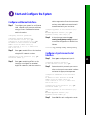
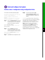
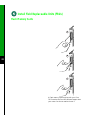
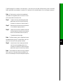
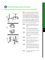
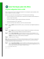
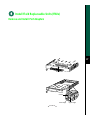
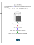
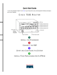
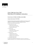
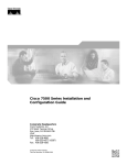
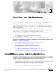
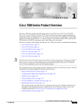
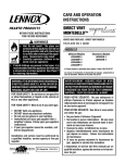
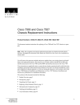
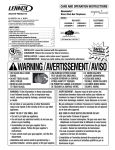
Quick Start Guide
Is Cisco documentation helpful? Click here or go to http://www.cisco.com/warp/public/732/docsurvey/rtg/ to
give us your feedback.
CISCO 7507 ROUTER
LO W ER
POW ER
NORMAL
57105
UP ER
POW ER
1
INSTALL THE HARDWARE
2
CONNECT THE RSP
3
START AND CONFIGURE THE SYSTEM
4
INSTALL FIELD REPLACEABLE UNITS (FRUS)
5
Install the Hardware
Captive
installation screw
DC
AC
FA
IL
PO
WE
R
EN
NO
AB
RM
LE
AL
Upper
power supply
Chassis
grounding
receptacles
EJ
EC
T
SL SLO
OT T
0 1
I
SL MA
AV ST
E ER
O
SL
AV
E/M
AS
TE
R
Captive
installation screw
CP
U
HA
LT
EN
AB
RE
LE
SE
T
DC
AC
FA
IL
PO
WE
H3888
R
Lower
power supply
AU
X.
NS
OL
E
I
ROUTE SWITCH PROCESSOR 2
CO
1
O
Slot 0
1
2
3
4
5
6
RSP slots
The Cisco 7507 has seven slots: slots 2 and 3 for the
Route Switch Processors (RSPs), and slots 0, 1, 4, 5,
and 6 for the interface processors. There are bays for
up to two AC-input or DC-input power supplies.
One power supply is shipped as standard equipment;
a second power supply is optional. A second
(optional) power supply allows load sharing and
increased system availability.
Packing List
•
1 Cisco 7507 router
•
1 Route Switch Processor (RSP)
•
Y-Adapter cables, 1 auxiliary and 1 console
•
1 AC power supply
•
1 AC power supply cable
•
1 Power cord
•
1 Anti-static wrist strap and documentation
Install the Hardware
Prepare to Install the Router
Note For detailed hardware installation
instructions and safety guidelines, refer to the Cisco
7500 Series Router Installation and Configuration
Guide, Site Preparation and Safety Guide, and the
Cisco 7500 Regulatory Compliance and Safety
Guide.
Warning Only trained and qualified
•
One 7/16-inch open-end (or adjustable) wrench
if you will remove the chassis feet
•
Tape measure or level (both optional)
•
Ohmmeter if your installation requires the
chassis be electrically isolated from the rack
•
Number 2 Phillips or 1/4-inch flat-blade
screwdriver for the power supply (Due to
product improvements, some power supplies use
slotted screws, and others use Phillips screws.)
Cable ties may be needed to temporarily anchor
the cables when installing the power supplies.
personnel should install, replace, or service
this equipment.
Step 1
Lift the router safely out of the packing
container.
•
Step 2
Ensure the power service at the site is
suitable for the router you are installing.
For DC-Input Power Supply:
2
Step 3
Step 4
Check the packing slip to ensure that all
the proper components are present.
Confirm that you have the required tools
and parts:
•
Twin-lead, 10-AWG cable terminal block
connection
•
Single 10-AWG wire for the ground connection
•
Number 1 Phillips or 3/16-inch flat-blade
screwdriver
For rack-mounting (optional):
For interface modules (optional):
•
Two mounting brackets (left and right are
identical), each with an attached spanner bar
•
•
Two chassis ears (each holds two captive
grommets)
•
Fasteners
•
Ten 10-32 x 5/8-inch LG Phillips pan-head
screws with integral washers
•
Four M4 x 10-mm LG Phillips, flat-head screws
•
Number 2 Phillips screwdriver
Number 1 Phillips or 3/16-inch flat-blade
screwdriver
Install the Hardware
Install the Router
DC
AC
FAIL
POW
NO
ER
EN
RM
AB
LE
AL
EJ
EC
T
SL SLOT
OT
0 1
I
SL MAST
AV
E ER
O
SL
AV
E/M
CP
RE
DC
AC
AS
U
TE
HA
SE
R
LT
EN
AB
LE
T
FAIL
POW
ER
AU
I
NS
X.
OL
E
ROUTE SWITCH PROCESSOR 2
CO
53488
O
3
Note To rack-mount the router, refer to the
Step 2
Ensure that you have at least 3 or 4 feet
(0.91 to 1.22 m) of clearance around the
rear of the chassis to install power
supplies and perform maintenance on the
chassis.
Step 3
Proceed to the “Install Interface
Processors, Fillers, VIPs, or RSPs” section
on page 10.
“Rack-Mount the Router (Optional)” section on
page 4.
Caution Two people are required to
perform this step. Avoid sudden twists or
moves to prevent injury.
Step 1
With a person positioned at either side of
the chassis, grasp the bottom edge of the
chassis with one hand near the front and
the other near the back. Slowly lift the
chassis in unison. Place the chassis on a
bench or tabletop where the air intake
vent on the front of the chassis is not
drawing in exhaust air from other
equipment.
Install the Hardware
Rack-Mount the Router (Optional)
53423
Bracket
M4 x 10-mm long Phillips
flat-head screws (to attach
ears to chassis)
4
To rack-mount a Cisco 7507 router, perform the
following steps:
Step 1
Mount the brackets to the rack posts.
Step 2
Secure the spanner bars.
Step 3
Attach the chassis ears.
Step 4
Mount the chassis.
Chassis ear with
captive sliding
grommets
10-32 x 5/8-inch long Phillips
pan-head screws with integral
square cone washers
(for mounting brackets and
chassis ears to rack posts)
Install the Hardware
Mount Brackets to the Rack Posts
Rack post
Flange
ide
ds
lde
53382
ie
Sh
5
Note The distance between the inner edges of the
left and right rack-mounting posts must be at least
17.72 inches (45.088 cm), and the distance between
the holes in the mounting posts must be 18.31 inches
(46.5 cm) (+ .063 inches or .16 cm).
Step 1
Step 2
Step 3
Place the bracket on the inner side of the
rack post, with the flanged front edge of
the bracket in front of the rack post.
Align the mounting holes in the bracket
with those in the rack post.
Support the bracket with one hand, and
use the other hand to insert a 10-32 x
5/8-inch LG Phillips pan-head screw
through the bottom mounting hole on the
front of the bracket and into the rack post.
Step 4
Secure the top of the bracket to the rack
with two pan-head screws. Finger-tighten
the screws.
Step 5
Push the brackets as far apart as possible
before using a Number 2 Phillips
screwdriver to tighten the screws.
Step 6
Adjust the brackets if the distance
between them is less than 17.5 inches
(45.45 cm).
Step 7
Repeat Step 3 through Step 6 for the
remaining bracket. Use a level or tape
measure to ensure that the two brackets
are level in the rack.
Install the Hardware
Secure the Spacers
A
C
53380
B
6
Step 1
Loosen the 10-32 x 5/8-inch LG Phillips
pan-head screw at the end of the ledge of
the right-side bracket. This screw is the
anchor for the spanner bar.
Step 2
Remove the tape that secures the spanner
bar on the left bracket, and swing the bar
down (see A) over the anchor screw on the
opposite bracket.
Step 3
If the spanner bar does not reach the
opposite bracket, loosen the pan-head
screws to allow more play between the
brackets.
Step 4
Repeat Step 1 through Step 3 to fasten the
remaining spanner bar to its anchor screw.
(See C.)
Step 5
Push the brackets as far apart as possible
before tightening the screws.
Step 6
Use a Number 2 Phillips screwdriver to
tighten the six pan-head screws that
secure the brackets to the rack-mounting
posts, and the two anchor screws that
secure the spanner bars. (See B.)
Step 7
Adjust the brackets if the distance
between them is less than 17.5 inches
(44.45 cm).
Install the Hardware
Attach the Chassis Ears
Center-mount
position
Flush-mount
position
H2297
OR
Step 1
Position the ears on the chassis as follows:
•
To flush-mount the chassis, place each ear so
that the mounting strips are flush with the end of
the chassis, and align the mounting holes in the
ear with those in the chassis.
•
To center-mount the chassis, place each ear with
the mounting strips away from the end of the
chassis, and align the mounting holes in the ear
with those in the chassis.
Step 2
Use two M4 x 10-mm LG Phillips
flat-head screws to secure each ear to the
chassis.
7
Install the Hardware
Mount the Chassis in the Rack
H2298
8
Warning Two people are required to
perform this step.
Step 1
Slowly lift the chassis in unison. Lower it
until it rests on the two ledges of the
brackets.
Step 2
Slide the chassis back into the rack along
the ledges.
Step 3
To remove a chassis foot, use a 1/4-inch
flat-blade screwdriver or insert a
7/16-inch open-end wrench between the
underside of the chassis and the foot.
Install the Hardware
Remove the Chassis Foot
Chassis foot
removal 7/16" nut
Flat-blade screwdriver
slot for removing
chassis foot
Step 4
Turn the foot counterclockwise to loosen
it until the foot drops out of the chassis.
Step 5
Continue sliding the chassis into the rack
until the ears meet the front mounting
posts on both sides of the rack.
Chassis foot
Step 6
H1396a
Underside of chassis
Secure each ear to the rack-mounting post
with two 10-32 x 5/8-inch LG Phillips
pan-head screws.
9
Install the Hardware
Install Interface Processors, Fillers, VIPs, or RSPs
Card carrier guide (black)
A
The Route Switch Processor (RSP) comes uninstalled
with your Cisco 7507 router, but is a required system
component. Install the RSPs in the slot 2 or slot 3,
and install any interface processors, fillers, or
Versatile Interface Processors (VIPs) in slots 0, 1, 4,
5, and 6 (optional).
Step 1
Hold the interface processor, filler, VIP, or
RSP with one hand, and place your other
hand under the carrier to support the card
and guide it into the slot. Avoid touching
the card.
Step 2
Place the interface processor, filler, VIP, or
RSP in the slot and align the guide on the
carrier with the groove in the slot.
Step 3
Carefully slide the interface processor,
filler, VIP, or RSP into the slot until the
faceplate makes contact with the ejector
levers.
Step 4
Use the thumb and forefinger of each hand
to push the ejector lever flat against the
interface processor, filler, VIP, or RSP.
Step 5
Use a screwdriver to tighten the captive
installation screws.
Step 6
Repeat Step 1 through Step 5 to install
any additional interface processors, fillers,
VIPs, or RSPs.
Step 7
To check an RSP installation, refer to the
“Check the RSP Installation” section on
page 30, and refer to the “Check the
Interface Processor or VIP Installation”
section on page 31 to check the interface
processor or VIP installation.
Captive
installation
screw
B
10
53375
C
Install the Hardware
Install Power Supplies in the Router
separate available power sources, connect each
power supply to separate input lines—the second
power source will likely be available during a failure.
Step 1
DC
IL
FA
AC
WER
PO
tive
allation
ew
For DC-input power supplies, turn off the
circuit breaker to which you will connect
power, and tape the breaker switch to the
off position.
I
0
This procedure applies to AC-input and DC-input
power supplies, with differences clearly noted. Do
not mix AC-input and DC-input power supplies in
the same chassis. Install the first power supply in the
lower power supply bay and the second, if any, in the
upper bay. In systems with dual power supplies and
For AC-input power supplies, confirm
that the power on the power supply is off.
Step 2
Hold the power supply by the handle and
place your other hand underneath it.
Caution Use two hands to remove and
install power supplies.
Step 3
Place the power supply inside the bay, and
align it to go straight into the bay.
Step 4
Push the power supply back into the bay
until its front panel is flush with the
chassis rear panel.
11
Step 5
Use a screwdriver to tighten the captive installation screw on the top of the power supply.
Note For DC-input power supplies, refer to the “Install the DC-Input Power Supply” section on page 13 to
complete this procedure.
12
Step 6
Push the cable retention clip away from the power supply receptacle, and push the power cable in
until the cable retention clip snaps into place.
Step 7
Connect the opposite end of the power cable to an appropriate power source.
Step 8
Repeat Step 1 through Step 7 to install the second power supply (optional).
Install the Hardware
Install the DC-Input Power Supply
Captive installation screws
on terminal block cover
DO NOT SHIP WITH POWER SUPPLY
INSTALLED
R TO BE FULLY ENGAGED
OPERATING POWER SUPPLY
FASTENER TO BE FULLY ENGAGED
BEFORE OPERATING POWER SUPPLY
13
OU
INP
TF
UT
AIL
PO
WE
R
INPUT VOLTAGE : 40-72 V=
INPUT CURRENT : 24-13A
I
allation screws
l block cover
O
B
NO SERVICEABLE COMPONENTS INSIDE
Note Perform Step 1 through Step 5 on the previous page before following the steps below.
Step 1
Using a screwdriver, loosen the captive installation screws on the terminal block cover.
Step 2
Step 3
Lift and remove the terminal block cover.
Wire the DC power supply using the appropriate lugs at the wiring end.
Note The proper wiring sequence is ground to ground, positive to positive (line to L), and negative to negative
(neutral to N). The ground wire should always be connected first and disconnected last.
14
Step 4
Attach two nylon ties around the cable and the metal bracket for strain relief.
Step 5
Install the terminal block cover over the terminal block, and tighten the captive installation screws.
Do not overtighten screws.
Step 6
Connect the opposite end of the DC-input cable to the DC power source.
Step 7
Remove the tape from the circuit breaker and turn the circuit breaker to the on position.
Step 8
Repeat Step 1 through Step 7 to install a second DC-input power supply, if any.
Connect the RSP
The auxiliary port on the RSP is an ETA/TIA DTE
DB-25 plug to which you can attach external
equipment in order to access the router from the
network. The port is located next to the console port
on the RSP and is labeled AUX.
DB-25 female
terminal
DB-25 male
RSP
Step 1
Connect the cable from the auxiliary
device to the auxiliary port on the RSP.
Step 2
Check your terminal’s documentation to
determine the baud rate of the terminal.
Note The baud rate of the terminal must match the
default baud rate (9600 baud).
Step 3
Connect the Console Port
The system console port on the RSP is a DB-25
receptacle DCE port for connecting a data terminal,
which allows you to configure and manage the
system. The console port is labeled Console.
Step 1
Connect the console cable from the
terminal to the console port on the RSP.
Step 2
Check your terminal’s documentation to
determine the baud rate of the terminal
you will be using.
Note The baud rate of the terminal you are using
must match the default baud rate (9600 baud).
Step 3
Set up the terminal as follows: 9600 baud,
8 data bits, no parity, and 2 stop bits
(9600, 8N2).
Connect the Auxiliary Port
Set up the terminal as follows: 9600 baud,
8 data bits, no parity, and 2 stop bits
(9600, 8N2).
15
Connect the RSP
Connect the Console and the Auxiliary Y-Cables
AUXILIARY
H9720
CONSOLE
16
Auxiliary
to auxili
RSPs in
external
y equipment
DB-25
The console and auxiliary Y-cables allow you to
simultaneously connect the console or auxiliary
ports on two RSP2s, RSP4s, or RSP8s, to a single
console terminal, or external auxiliary device. These
are configured as system master and slave in slots 2
and 3 in the Cisco 7507.
DB-25 fe
DB-25 fe
H9721
Console
to cons
RSPs in
sole terminal
AUXILIARY
CONSOLE
DB-25
Step 1
Connect the DB-25 male end of the
Y-cable to the external auxiliary
equipment.
Step 2
Connect one DB-25 female end of the
Y-cable to auxiliary ports on an RSP in an
RSP slot.
Step 1
Connect the DB-25 female end of the
Y-cable to the console terminal device.
Step 3
Repeat Step 2 for the auxiliary ports on a
second RSP in an RSP slot.
Step 2
Connect one DB-25 male end of the
Y-cable to an RSP or other external
auxiliary device.
Step 4
Step 3
Repeat Step 2 for the other RSP or other
external device.
Connect the interface processors or VIPs
to the external network. Refer to the
appropriate processor module manual,
such as the Route Switch Processor
(RSP4/4+) Installation and Configuration
Guide.
Start and Configure the System
Step 1
Check the following components to make sure they are secure:
•
Each interface processor is inserted all the way into its slot, and captive installation screws are tightened.
•
All interface cable connections are secured, and
any Flash memory cards are secured in their PC
slots.
•
The system power cable is connected.
•
Check the console terminal to make sure it is
connected to the console port and turned on.
Step 2
Step 3
Step 4
Step 5
Step 6
Turn the system power switch to the on (|)
position. The green AC (or DC) OK and
fan OK LEDs on each power supply
should go on. After a few seconds, the red
output fail LED will turn off.
Listen for the system blower; you should
immediately hear it operating.
Observe the normal LED indicator on the
RSP. If this indicator is not on after system
initialization, an error has occurred. If
necessary, refer to Appendix A in the
Cisco 7500 Series Installation and
Configuration Guide.
Wait until the system boot is complete
before attempting to verify the status of
interface processor indicators. During the
boot process, the LED indicators on most
of the interfaces go on and off in irregular
sequence.
Observe the LED indicators on the
interface processors in your system. When
the system boot is complete (a few
seconds), the RSP begins to initialize the
interface processors. During this
initialization, the indicators on each
interface processor behave differently
(most flash on and off).
The enabled LED on each interface
processor goes on when initialization has
been completed, and the console screen
displays a script and system banner
similar to the following:
GS Software (RSP-K ), Version 11.1(8)CA
Copyright (c) 1986-1995 by Cisco Systems, Inc.
This RSP2 is system master
Other RSP2 is not plugged in
Compiled Wed 10-May-95 11:06
Step 7
Observe the system startup banner. When
you start up the router for the first time,
the system automatically enters the setup
command facility, which determines
which interfaces are installed and prompts
you for configuration information for
each one. On the console terminal, after
the system displays the system banner and
hardware configuration, you will see the
following System Configuration Dialog
prompt:
--- System Configuration Dialog --At any point you may enter a questions mark
`?' for help.
Refer to the `Getting Started' Guide for
additional help.
Default settings are in square brackets `[]'.
continue with configuration dialog? [yes]:
17
Start and Configure the System
Start a Basic Configuration
Step 7
Many privileged-level EXEC commands are used to
set operating parameters. To enter the
privileged-level:
•
AutoInstall (proceed to Step 8)
•
Setup facility (proceed to the “Perform a Basic
Configuration Using Setup” section on page 19)
•
Configuration mode (proceed to the “Perform a
Basic Configuration Using Configuration
Mode” section on page 23)
Step 1
Enter the enable command at the EXEC
prompt (>), and then enter a
privileged-level password, as follows:
Router> enable
Password:
Router#
Step 2
Enter the configure terminal command to
enter configuration mode:
Router# configure terminal
Enter configuration commands, one per line.
End with CNTL/Z.
Router(config)#
18
Step 3
Enter the config-register value
configuration command, where value is a
hexadecimal number preceded by 0x, as in
the following example:
Router(config)# config-register 0x010F
Reboot the router, and then perform a
basic configuration using:
Note Configuration register changes take effect
only when the system reloads, such as when you
issue a reload command from the console.
Configure Using AutoInstall
Step 8
Connect to the network using a serial
(WAN) cable to the channel service
unit/data service unit (CSU/DSU).
Step 9
Contact your system administrator to
verify that the TCP/IP host on your
network is preconfigured.
Step 4
Press Ctrl-Z to exit configuration mode.
Step 10 Press Ctrl-Z to exit configuration mode.
Step 5
Save the new settings to NVRAM. Enter
the copy running-config startup-config
command.
Step 11 At the # prompt, enter the copy
running-config startup-config command
to save the configuration to NVRAM as
follows:
Note The new settings do not take effect until the
system software is reloaded by rebooting the router.
Hostname# copy running-config startup-config
Step 6
This completes the procedure for performing a basic
configuration using AutoInstall.
Enter the show version command to view
the configuration register value currently
in effect. The value is displayed on the last
line of the screen display:
Configuration register is 0x141 (will be 0x101
at next reload)
Start and Configure the System
Perform a Basic Configuration Using Setup
Note The router’s serial (WAN) cable should not be
connected to the CSU/DSU unless you are planning
to use AutoInstall. If you are using the console
Y-cable that shipped with your router, use either of
the two DB-25 male plug ends of the Y-cable.
Step 1
Select the protocols supported on your
interfaces. For Internet Protocol (IP)-only
installations, accept the default values. A
typical minimal configuration using IP,
IPX, and AppleTalk follows:
Step 2
Enter the enable secret password and the
enable password when the following is
displayed:
The enable secret is a one-way cryptographic
secret used instead of the enable password
when it exists.
Enter enable secret: barney
The enable password is used when there is no
enable secret and when using older software
and some boot images.
Enter enable password: betty
Configuring global parameters:
Step 3
Enter host name [Router]: Router
Enter yes or no to accept or refuse SNMP
management:
Configure SNMP Network Management? [yes]: yes
Community string [public]:
Step 4
Enter no to refuse to enable CLNS:
Configure CLNS? [no]: no
Step 5
Enter yes to enable routing on AppleTalk
and IPX:
Configure AppleTalk? [no]: yes
Multizone networks? [no]: yes
Configure IPX? [no]: yes
Step 6
Configure
Configure
Configure
Configure
Enter no to refuse to enable Vines, XNS,
DECnet, or bridging:
Vines? [no]: no
XNS? [no]: no
DECnet? [no]: no
bridging? [no]: no
19
Step 7
Enter yes or press Return to configure IP, and then select an interior routing protocol for IP, if you are
using IP routing:
Configure IP? [yes]: yes
Configure IGRP routing? [yes]: yes
Your IGRP autonomous system number [1]: 15
Step 8
At the # prompt, enter the copy
running-config startup-config command
to save the configuration to NVRAM as
follows:
Hostname# copy running-config startup-config
Note Consult your network administrator to
obtain network addresses and subnet mask
information.
20
Start and Configure the System
Configure an Ethernet Interface
Step 1
To configure your system for an Ethernet
LAN, respond to the prompts as follows,
using your own IP address and subnet
mask information:
cable range number. Enter the zone name
and any other additional zones that will
be associated with your local zone:
Configure AppleTalk on this interface? [no]:
yes
Extended AppleTalk network? [no]: yes
AppleTalk starting cable range [0]:
Configuring interface parameters:
Configuring interface Ethernet0/0:
Is this interface in use? [no]: yes
Configure IP on this interface? [no]: yes
IP address for this interface: 1.1.1.10
Number of bits in subnet field [0]:
Class A network is 1.0.0.0, 0 subnet bits;
mask is 255.0.0.0
Step 2
Enter yes to enable IPX on this interface,
using the IPX network number:
Configure IPX on this interface? [no]: yes
IPX network number [2]:
Step 3
Enter yes to enable AppleTalk on this
interface, to configure for extended
AppleTalk networks, and then enter the
Step 4
At the # prompt, enter the copy
running-config startup-config command
to save the configuration to NVRAM as
follows:
Hostname# copy running-config startup-config
Configure a Synchronous Serial
Interface
Step 1
Enter yes to configure serial port 0:
Configuring interface Serial1/0:
Is this interface in use? [no]: yes
Step 2
Determine which protocols you want to
allow on the synchronous serial interface
and enter the appropriate responses:
Configure IP unnumbered on this interface?
[no]:
IP address for this interface: 1.1.1.20
Number of bits in subnet field [0]:
Class A network is 1.0.0.0, 0 subnet bits;
mask is 255.0.0.0
Configure IPX on this interface? [no]: yes
IPX network number [2]:
Configure AppleTalk on this interface? [no]:
yes
Extended AppleTalk network? [no]:
AppleTalk network number [1]:
Step 3
Press Ctrl-Z to exit configuration mode.
21
Step 4
At the # prompt, enter the copy running-config startup-config command to save the configuration to
NVRAM as follows:
Hostname# copy running-config startup-config
Your Cisco 7507 router is now minimally configured
and ready to use. If you want to modify the
parameters after the initial configuration, use the
setup command. To perform more complex
configurations, use the configure command. For
more information on additional interface
configuration and information on more specific
system configurations, refer to the Cisco 7500 Series
Installation and Configuration Guide.
22
Start and Configure the System
Perform a Basic Configuration Using Configuration Mode
At the reboot, the following example appears:
Any interface listed with OK? value "NO" does
not have a valid configuration.
Interface IP-Address OK? Method Status
Protocol
Ethernet0/0 unassigned NO not set down down
Serial1/0 unassigned NO not set down down
Step 1
Enter the configure terminal command at
the enable prompt to enter configuration
mode from the terminal, as follows:
Router# configure terminal
Enter configuration commands, one per line.
End with CNTL/Z.
Router(config)#
Step 2
Enter the interface type slot/port
command at the enable prompt to enter
interface configuration mode, as follows:
Router(config)# interface serial slot/port
Router(config-if)#
Step 3
Press Ctrl-Z to exit configuration mode.
Step 4
At the # prompt, enter the copy
running-config startup-config command
to save the configuration to NVRAM as
follows:
Hostname# copy running-config startup-config
Your Cisco 7507 router is now minimally configured
and ready to use. If you want to modify the
parameters after the initial configuration, use the
setup command. To perform more complex
configurations, use the configure command. For
more information on additional interface
configuration and information on more specific
system configurations, refer to the Cisco 7500 Series
Installation and Configuration Guide.
23
Install Field Replaceable Units (FRUs)
Flash Memory Cards
NO
RM
AL
A
SL SL
OT OT
0 1
M
AV AST
ER
E
SL
NO
RM
AL
B
24
SL SL
OT OT
0 1
M
AV AST
ER
E
SL
NO
RM
AL
C
SL SL
OT OT
0 1
M
AV AST
ER
E
57002
SL
A Flash memory card that ships with your Cisco
7507 contains the Cisco IOS software image to boot
your router. You do not need to format it.
The RSP has two PC Card slots—slot 0 and slot 1—into which you can install a Flash memory card. In the RSP2,
RSP4, and RSP8, the orientation is vertical. PC Card slot 0 is on the left and slot 1 is on the right (as shown).
Note A Flash memory card can be inserted and
removed with the system power on. Both PC Card
slots can be used at the same time.
Step 1
To eject the card, press the appropriate
eject button until the card is free of the
connector at the back of the slot (see C).
Step 2
Remove the card from the slot and place it
in an antistatic bag to protect it.
Step 3
Face the front panel of the RSP, and hold
the Flash memory card with the connector
end of the card toward the slot (see A).
The label should face right.
Note The Flash memory card is keyed and cannot
be seated the wrong way. The eject button will not
pop out if the card is not properly inserted.
Step 4
Insert the card into the appropriate slot
until the card completely seats in the
connector at the back of the slot and the
eject button pops out toward you (see B).
Note The card does not insert all the way inside the
RSP; a portion of the card remains outside of the
slot. Do not attempt to force the card past this point.
25
Install Field Replaceable Units (FRUs)
Format a Flash Memory Card
Flash memory cards shipped as spare parts must be
formatted. Use only Intel Series 2+ Flash memory
cards.
An example of the copy tftp:filename command
follows for a file in the Flash memory card in PC
Card slot 0:
Step 1
Router# copy tftp:myfile1 slot0:myfile1
Enter format slot0: (or format slot1:) to
format the Flash memory card, as follows:
Router# format slot0:
Step 2
At the erase all sectors prompt, press
Enter to proceed.
All sectors will be erased, proceed? [confirm]
Step 3
26
At the volume ID prompt, enter the ID
name:
Enter volume id (up to 30 characters):
MyNewCard
Formatting sector 1
Format device slot0 completed
Router#
Copy Files to Flash Memory
To upgrade to a new Cisco IOS image, copy the
image file to Flash memory. Upgrade images one at a
time; do not delete all known good images at one
time. You cannot copy an image while the system is
running from Flash memory.
Use the command copy tftp:filename [bootflash |
slot0 | slot1]: filename for the copy procedure, where
tftp:filename is the source of the file and [bootflash |
slot0 | slot1]: filename is the destination in bootflash
memory or on either of the Flash memory cards.
20575008 bytes available on device slot0,
proceed? [confirm]
Address or name of remote host [1.1.1.1]?
Loading new.image from 1.1.1.1 (via
Ethernet1/0):
!!!!!!!!!!!!!!!!!!!!!!!!!!!!!![OK 7799951/15599616 bytes]
CCCCCCCCCCCCCCCCCCCCCCCCCCCCCCCCCCCCCCCCC
Router#
Install Field Replaceable Units (FRUs)
Make a Flash Memory Card Image Bootable
Note In this example, the filename is new.image,
and the Flash memory card is located in slot 0.
Step 1
Enter the configure terminal command at
the enable prompt, as follows:
Router# configure terminal
Step 2
Enter the no boot system command, as
follows.
Router(config)# no boot system
Step 3
Enter the boot system flash
slot0:new.image command, as follows:
Router(config)# boot system flash
slot0:new.image
Step 4
Enter the config-register 0x2102
command to enable loading an image
from Flash memory:
Router(config)# config-register 0x2102
Step 5
Press Ctrl-Z to exit configuration mode.
Step 6
Enter the copy running-config
startup-config command to save the
configuration to NVRAM as follows:
To enable booting from Flash memory, set
configuration register bits 3, 2, 1, and 0 to a value
between 2 and 15 in conjunction with the boot
system flash device:filename configuration
command, where device is bootflash:, slot0:, or
slot1:, and filename is the name of the file from
which you want to boot the system. In the following
example, the Flash memory card is in slot 0.
Step 1
Router# configure terminal
Step 2
Enter the reload command. When the
system reloads, it will boot the image
new.image from the Flash memory card in
slot 0.
Router# reload
Enable Booting from Flash
Memory
At the prompt, enter configuration
commands, one per line.
Enter configuration commands, one per line.
Step 3
Press Ctrl-Z to exit configuration.
Step 4
Enter the boot system flash
bootflash:slot0: filename command, as
follows:
Router(config)# boot system flash
blootflash:slot0:filename
Step 5
Hostname# copy running-config startup-config
Step 7
Enter the configure terminal command at
the enable prompt, as follows:
Enter the config-register command with
the value shown in the following example:
Router(config)# config-reg 0x0102
Ctrl-Z
Router#
Step 6
Press Ctrl-Z to exit enable booting mode.
27
Install Field Replaceable Units (FRUs)
Prepare to Remove and Install
an RSP
To remove and install an RSP, you will perform the
following steps:
28
•
Copy the configuration file using a Trivial File
Transfer Protocol (TFTP) server
•
Remove the RSP
•
Install the RSP
•
Connect to the RSP
•
Turn the system power back on, if it has been
turned off
•
Retrieve the configuration file
•
Configure high system availability (HSA) or high
availability (HA) features, provided you are
using two RSPs (Follow the instructions in the
appropriate Route Switch Processor Installation
and Configuration Guide, such as the Route
Switch Processor 8 (RSP8) Installation and
Configuration Guide.)
Note The high system availability (HSA) and high
availability (HA) features are beyond the scope of
this Quick Start Guide. For information on
configuring your router for HSA or for HA, refer to
the appropriate Route Switch Processor Installation
and Configuration Guide, such as the Route Switch
Processor 8 (RSP8) Installation and Configuration
Guide.
Install Field Replaceable Units (FRUs)
Remove and Install an Interface Processor, Filler, VIP, or RSP
Note Do not shut down the system power when
removing an interface processor, VIP, or an RSP in a
system configured for high availability HA. If you
are removing an RSP and have only one RSP, shut
down the system, but first copy the configuration file
to a TFTP server. See the “Copy the Configuration
File for an RSP” section on page 32. If you have a
system using high system availability (HSA), shut
down the system to remove the master RSP, but leave
power on if you remove only the slave RSP.
Bottom ejector lever
A
Captive
installation
screw
Card
carrier
guide
Card
slot
B
Step 1
Attach an ESD-preventive wrist strap
between you and any unpainted chassis
surface.
Step 2
If you have a VIP4 and are using HSA
with an RSP2 as the slave processor,
remove the RSP2 and wait 20-30 seconds.
Step 3
Disconnect all cables from the interface
processor, VIP, or RSP port adapters;
unless you are only moving a carrier, then
skip this step.
Step 4
Use a screwdriver to loosen the captive
installation screws, as shown in A.
Step 5
Place your thumbs on both ejector levers
and simultaneously pull them both
outward, as shown in B.
Step 6
Grasp the interface processor, filler, VIP,
or RSP handle with one hand and pull the
carrier straight out of the slot, keeping
your other hand under the carrier to guide
it.
Step 7
Store the interface processor, VIP, or RSP
in an antistatic bag.
STOP!
on contact
53376
C
29
Install Field Replaceable Units (FRUs)
Step 8
Step 9
If you have a VIP4 and are using HSA
with an RSP2 as the slave processor, wait
20-30 seconds, then reinsert the RSP2.
Note Boot time is approximately 1 minute for
Repeat Step 2 through Step 8 to remove
any additional interface processors, fillers,
VIPs, or RSPs.
Step 4
Verify that all the enabled LEDs (on the
interface processors) are on.
Step 5
In systems with a second RSP installed
(and HSA or HA configured), use the
show version command to verify that the
slave (or standby) RSP is recognized by
the system.
Step 6
When you have verified all the conditions
in Step 1 through Step 4 (or Step 5 if you
have a second RSP installed and want to
use the HSA or HA features), the
installation is complete.
systems with one RSP and approximately 1.5
minutes for systems with two RSPs.
Step 10 Perform the steps in the “Install Interface
Processors, Fillers, VIPs, or RSPs” section
on page 10 to install an interface
processor, filler, VIP, or RSP.
Check the RSP Installation
Step 1
•
30
•
Check the RSP connections to make sure
they are secure:
The RSP is inserted all the way into its slot, and
both the captive installation screws are
tightened.
The console terminal is turned on and is
connected to the console port.
Step 2
Observe the RSP LEDs. While the system
initializes, the CPU halt LED on the RSP
stays on. It goes off when the boot process
is complete. As the RSP initializes each
interface processor, the status LEDs on
each interface processor go on and off in
irregular sequence.
Step 3
Verify that the console terminal displays
the system banner and startup screen as
the system restarts.
If you replaced the RSP and saved your configuration
file to a remote server before doing so, proceed to the
“Retrieve the Configuration File for RSPs” section
on page 35.
An error condition exists if no LEDs go on at power
up or after initialization, or if the boot error or CPU
halt LEDs go on and remain on. If this happens, see
Appendix A in the Cisco 7500 Series Installation and
Configuration Guide.
Install Field Replaceable Units (FRUs)
Check the Interface Processor or VIP Installation
Note When a new VIP is inserted or when a VIP is
•
moved to a new slot, the system recognizes the new
interfaces, but leaves them in the shutdown state
until you configure them. After the system
reinitializes all interfaces, the enabled LED on the
port adapters and on all interface processors, VIPs,
and RSPs should go on, depending on your
connections and configuration.
Router> enable
Password:
Router#
•
Use the configure command to configure the
interface processor or VIP.
Step 1
•
Refer to the appropriate configuration section of
your port adapter documentation to configure
the port adapter.
Observe the console display messages
when the system reinitializes each
interface as follows:
•
For a new interface processor or VIP, the system
should recognize all new interfaces, but leave
them configured as down.
•
For a replaced interface processor or VIP, the
system should recognize each interface and place
it in the same state (up or down) each was in
when you removed the interface processor or
VIP.
Step 2
Step 4
If the VIP is new, configure the new
interfaces.
If the VIP is a replacement, use the show
interfaces type slot/port adapter/port or
show controllers cbus command to verify
the status of the interfaces.
If you replaced a VIP with a new VIP with
a greater number of ports (for example, if
you replaced a single-port adapter VIP
with a dual-port adapter VIP), the system
will recognize the interfaces on the
previously configured port adapter, but
will not recognize the additional port
adapter interfaces. The new interfaces will
remain in the shutdown state until you
configure them.
Verify that the enabled LED on each port
adapter goes on and remains on.
If the enabled LED on a port adapter fails
to go on, the interface processor or VIP
may not be fully seated in the backplane.
Refer to Appendix A in the Cisco 7500
Series Installation and Configuration
Guide.
Step 3
Enter the enable command at the EXEC prompt
(>), and then enter a privileged-level password,
as follows:
Step 5
When the interfaces are up, check the
activity of each interface by observing the
status LEDs, which are described in the
LED section of your port adapter
documentation.
31
Install Field Replaceable Units (FRUs)
Copy the Configuration File for an RSP
Refer to the appropriate Cisco IOS software documentation for the configuration options available, and for
specific configuration instructions, as needed.
Before you copy (save) the running configuration to a TFTP file server, ensure the following:
•
You have a connection to the router either with a console terminal connected to the RSP console port or
remotely through a Telnet session.
•
The router is connected to a network supporting a file server (remote host).
•
The remote host supports the TFTP application.
•
You have the interface processor address or name of the remote host available.
Step 1
32
Enter the enable command at the EXEC prompt (>), and then enter a privileged-level password, as
follows:
Router> enable
Password:
Router#
Step 2
Enter the ping command followed by the name or IP address of the remote server, and then press
Return to check the connection between the router and the remote host.
Step 3
Enter the show running-config command to display the currently running configuration on the
terminal and ensure that the configuration information is complete and correct. If it is not, use the
configure command to add or modify the existing configuration.
Step 4
Create a file on the TFTP server.
Note Before you can save a file to a TFTP server, a file must first exist on the TFTP server. Create this file.
Ensure that the filename matches the filename you will copy from the router. Also, ensure that the server
permissions are set so the router can copy to this file.
Step 5
Enter the copy startup-config tftp command. The EXEC command interpreter prompts you for the
name or interface processor address of the remote host that is to receive the configuration file. (The
prompt might include the name or address of a default file server.)
Router# copy startup-config tftp
Remote host []?
Step 6
Enter the name or IP address of the remote host. In the following example, the name of the remote
server is servername:
Router# copy startup-config tftp
Remote host []? servername
Translating "servername"...domain server (1.1.1.1) [OK]
33
Install Field Replaceable Units (FRUs)
Step 7
Enter the name of the configuration file. The default is to use the name of the router with the suffix
-confg. Press Return to accept the default filename, or enter a different name for the file, then press
Return. In the following example, the default is accepted:
Name of configuration file to write [Router-confg]?
Write file Router-confg on host 1.1.1.1? [confirm]
Writing Router-confg .....
Step 8
The system displays the instructions you entered for confirmation. If the instructions are not correct,
enter n (no), and then press Return to cancel the process. To accept the instructions, press Return, or
press y and then press Return. In the following example, the default is accepted:
Write file Router-confg on host 1.1.1.1? [confirm]
Writing Router-confg: !!!! [ok]
The system displays a series of exclamation points
(! ! !) or periods (. . .) during the copy process. The !!!! and [ok] indicate that the operation was successful. A
series of periods (...) and [timed out] or [failed] indicates a failure of the process.
34
If the display indicates that the process was
successful, the copy process is complete. The
configuration is stored on the remote file server.
If the display indicates that the process failed, the
configuration was not saved (see the following
example):
Writing Router-confg .....
Repeat the preceding steps, or select a different
remote file server and repeat the preceding steps.
After you upload the configuration file, continue
with the “Remove and Install an Interface Processor,
Filler, VIP, or RSP” section on page 29 to install the
RSP. If you are unable to copy the configuration to a
remote host successfully, contact your network
administrator or contact Cisco technical assistance.
Install Field Replaceable Units (FRUs)
Retrieve the Configuration File for RSPs
Retrieve the saved configuration and copy it to NVRAM by accessing the router through a console terminal, or
from a remote terminal.
Step 1
Enter the enable command at the EXEC prompt (>), and then enter a privileged-level password, as
follows:
Router> enable
Password:
Router#
Note The router runs from the default configuration in NVRAM until the previous configuration is retrieved.
Passwords configured on the previous system are not valid until they are retrieved.
Step 2
Enter the ping command followed by the name or IP address of the remote server, and then press
Return to check the connection between the router and the remote host.
Step 3
Enter the copy tftp startup-config
command and press Return to enter the
configuration mode and specify that you
will configure the system from a network
device (instead of from the console
terminal, which is the default).
Router# copy tftp startup-config
Step 4
Enter the IP address or name of the remote
host (the remote TFTP server to which
you originally saved the configuration
file).
Address of remote host [255.255.255.255]?
10.1.1.1
Step 5
Enter the name of the configuration file.
The default is to use the name of the
router with the suffix -confg
(Router-confg in the following example).
If you specified a different filename when
you copied the configuration, enter the
filename; otherwise, press Return to
accept the default.
Name of configuration file [Router-confg]?
Step 6
Before the system reloads the new
configuration file in NVRAM, it displays
the instructions you entered for
confirmation. If the instructions are not
correct, enter n (no), and then press
Return to cancel the process. To accept the
instructions, press Return, or press y and
then press Return. Output similar to the
following appears:
Configure using Router-confg from 10.1.1.1?
[confirm]
Loading Router-confg from 10.1.1.1: ! ! [OK 1186/126927 bytes]
Warning: distilled config is not generated
[OK]
%SYS-5-CONFIG_NV: Non-volatile store
configured from Router-confg by console tftp
from 10.1.1.1
35
Install Field Replaceable Units (FRUs)
The console display indicates whether or not the operation was successful. A series of exclamation points (!!!!)
and [OK] (as shown in the preceding example) indicates that the operation was successful. A series of periods (.
. .) and [timed out] or [failed] indicates a failure due to a network fault or an incorrect server name, address, or
filename). The following is an example of a failed attempt to boot from a remote server:
Booting Router-confg ..... [timed out]
If the display indicates that the process was successful, as shown in Step 6, proceed to the next step.
If the display indicates that the process failed, verify the name or IP address of the remote server and the filename,
and repeat the preceding steps. If the process fails again, contact your network administrator.
Step 7
36
Enter the show startup-config command
to confirm that the configuration file was
retrieved correctly. Look at the first line
for the configuration file size. Compare it
with the file you retrieved from the TFTP
server to confirm that it is correct.
Following is an example:
Router# show startup-config
Using 1186 out of 126968 bytes
!
version 12.0(9)S
hostname Router
!
Router#
Step 8
To ensure that the startup configuration
file stored in NVRAM is the default
running configuration file used by the
system, enter the copy
system:running-config
nvram:startup-config command:
Router# copy system:running-config
nvram:startup-config
Router#
%SYS-5-CONFIG_I: Configured from memory by
console
Router#
This completes the process for retrieving the
configuration file for the RSP.
Install Field Replaceable Units (FRUs)
Remove and Install Port Adapters
37
A
Screw
B
Carrier
Lower edge
Upper edge
Note First remove the VIP from the chassis before removing the port adapter from the VIP. See the “Remove
and Install an Interface Processor, Filler, VIP, or RSP” section on page 29 for instructions.
38
Step 1
Remove the screw that secures the port adapter (or blank port adapter), as shown in A.
Step 2
Grasp the handle and carefully pull it out of its slot, away from the edge connector at the rear of the
slot. (See A.)
Step 3
To insert the port adapter, align the carrier between the upper and the lower edges of the port adapter
slot. (See B.)
Step 4
Carefully slide the port adapter into the slot until the connector is completely seated in the connector
at the rear of the port adapter slot, as shown in B.
Step 5
Install the screw in the rear of the port adapter slot on the VIP. Do not overtighten the screw. (See A.)
Step 6
Carefully slide the VIP motherboard into the interface processor slot until the connectors at the rear
of the VIP are completely seated in the connectors at the rear of the interface processor slot. Use the
ejector levers to seat the VIP in the interface processor slot. Tighten the captive installation screws on
the VIP.
(See C.)
Install Field Replaceable Units (FRUs)
Remove and Replace the Power Supply
Redundant power supplies support online insertion and removal (OIR); if you remove one power supply, the
second power supply immediately ramps up to maintain uninterrupted operation. In this case, proceed to Step 2.
If you have only one power supply, you must turn off power before removing and replacing it. In this case,
proceed to Step 1.
Step 1
Turn off the power source.
Step 2
Turn off the switch on the power supply.
Step 3
Disconnect the power cable from the power source.
Step 4
Disconnect the power cable from the power supply.
For the AC-input power supply: Lift up the cable retention clip and remove the power cable from the
AC power receptacle.
39
Captive
installation
screw
DC
R
WE
IL
FA C PO
A
LEDs
Powe
front
AC power
receptacle
O
On/off switch
H1314a
I
Locking device
Install Field Replaceable Units (FRUs)
For the DC-input power supply: Use a screwdriver to loosen the captive installation screws on the
terminal block cover, lift the cover, use the wire cutters to cut the nylon strain-relief ties, and then
remove the three power leads (remove the ground lead last) from the terminal block. See below.
OT SHIP WITH POWER SUPPLY
ALLED
FASTENER TO BE FULLY ENGAGED
BEFORE OPERATING POWER SUPPLY
Captive installatio
screw
Power leads attac
to terminal block
( ) negative
( ) positive
( ) ground
Step 7
Pull the power supply out of the bay and
put it aside.
Step 8
If the power supply bay is to remain
empty, install a power-supply filler plate
over the opening and secure it with a
mounting screw.
Step 9
Refer to the “Install Power Supplies in the
Router” section on page 11 to replace the
power supply.
Nylon ties on cab
and metal bracke
INPUT VOLTAGE : 40-72 V=
INPUT CURRENT : 24-13A
H2530
40
Warning Keep hands and fingers out of
the power supply bays. High voltage is
present on the power backplane when the
system is operating.
Step 5
Use a screwdriver to loosen and remove
the captive installation screw on the top of
the power supply.
Step 6
Grasp the power supply handle with one
hand and place your other hand
underneath to support the bottom of the
power supply.
Corporate Headquarters
Cisco Systems, Inc.
170 West Tasman Drive
San Jose, CA 95134-1706
USA
http://www.cisco.com
Tel: 408 526-4000
800 553-NETS (6387)
Fax: 408 526-4100
European Headquarters
Cisco Systems Europe
11, Rue Camille Desmoulins
92782 Issy Les Moulineaux Cedex
9
France
http://www-europe.cisco.com
Tel: 33 1 58 04 60 00
Fax: 33 1 58 04 61 00
Americas
Headquarters
Cisco Systems, Inc.
170 West Tasman Drive
San Jose, CA 95134-1706
USA
http://www.cisco.com
Tel: 408 526-7660
Fax: 408 527-0883
Asia Pacific Headquarters
Cisco Systems Australia, Pty., Ltd
Level 17, 99 Walker Street
North Sydney
NSW 2059 Australia
Tel: +61 2 8448 7100
Fax: +61 2 9957 4350
Cisco Systems has more than 200 offices in the following countries. Addresses, phone numbers, and fax numbers are listed on the
C i s c o C o n n e c t i o n O n l i n e We b s i t e a t h t t p : / / w w w. c i s c o . c o m / g o / o f fi c e s .
Argentina • Australia • Austria • Belgium • Brazil • Bulgaria • Canada • Chile • China • Colombia • Costa Rica • Croatia • Czech
Republic • Denmark • Dubai, UAE • Finland • France • Germany • Greece • Hong Kong • Hungary • India • Indonesia • Ireland Israel
Italy • Japan • Korea • Luxembourg • Malaysia • Mexico • The Netherlands • New Zealand • Norway • Peru • Philippines Poland
Portugal • Puerto Rico • Romania • Russia • Saudi Arabia • Scotland • Singapore • Slovakia • Slovenia • South Africa • Spain •
Sweden Switzerland • Taiwan • Thailand • Turkey • Ukraine • United Kingdom • United States • Venezuela • Vietnam • Z i m b a b w e
AccessPath, AtmDirector, Browse with Me, CCDA, CCDE, CCDP, CCIE, CCNA, CCNP, CCSI, CD-PAC, CiscoLink, the Cisco NetWorks logo, the Cisco Powered Network
logo, Cisco Systems Networking Academy, the Cisco Systems Networking Academy logo, Fast Step, Follow Me Browsing, FormShare, FrameShare, GigaStack, IGX,
Internet Quotient, IP/VC, iQ Breakthrough, iQ Expertise, iQ FastTrack, the iQ Logo, iQ Net Readiness Scorecard, MGX, the Networkers logo, Packet, RateMUX,
ScriptBuilder, ScriptShare, SlideCast, SMARTnet, TransPath, Unity, Voice LAN, Wavelength Router, and WebViewer are trademarks of Cisco Systems, Inc.; Changing the
Way We Work, Live, Play, and Learn, Discover All That’s Possible, and Empowering the Internet Generation, are service marks of Cisco Systems, Inc.; and Aironet, ASIST,
BPX, Catalyst, Cisco, the Cisco Certified Internetwork Expert logo, Cisco IOS, the Cisco IOS logo, Cisco Systems, Cisco Systems Capital, the Cisco Systems logo,
Enterprise/Solver, EtherChannel, EtherSwitch, FastHub, FastSwitch, IOS, IP/TV, LightStream, MICA, Network Registrar, PIX, Post-Routing, Pre-Routing, Registrar,
StrataView Plus, Stratm, SwitchProbe, TeleRouter, and VCO are registered trademarks of Cisco Systems, Inc. and/or its affiliates in the U.S. and certain other countries.
All other brands, names, or trademarks mentioned in this document or Web site are the property of their respective owners. The use of the word partner does not imply a
partnership relationship between Cisco and any other company. (0104R)
Printed in the USA on recycled paper containing 10% postconsumer waste.
78-13034-01
42