1
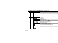
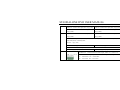
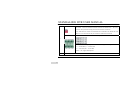
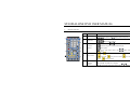
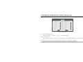
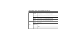
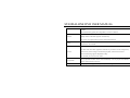
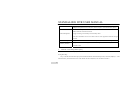
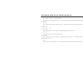
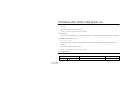
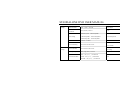
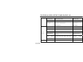
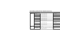
STANDALONE DVR
USER MANUAL
VER: 020811
contents
I Introduction............................................................................................................................................................... 1 1 Brief Introduction...................................................................................................................................................... 1 2 Main Features............................................................................................................................................................ 1 II Installation................................................................................................................................................................. 5 1 2 1) Front Panel of 4 and 8 Channel DVR ............................................................................................................ 5 3) Front Panel of 16 Channel DVR .................................................................................................................... 6 Rear Panel Description ............................................................................................................................................. 8 1) Rear Panel of 4 and 8 Channel DVR ............................................................................................................. 8 2) Rear Panel of 16 Channel DVR ....................................................................................................................11 3 Remote Controller................................................................................................................................................... 14 4 Hard Disk Installation ............................................................................................................................................. 15 5 III Front Panel Operation ............................................................................................................................................... 5 1) Installation of 4 and 8 Channel DVR..........................................................................................................115 2) Installation of 16 Channel DVR..................................................................................................................116 Rear Panel Connection............................................................................................................................................ 17 Menu Description.................................................................................................................................................... 19 contents
1 Menu Structure ........................................................................................................................................................ 20 2 Menu Operations ..................................................................................................................................................... 21 IV 1) General Operations ....................................................................................................................................... 21 2) Menu Selection ............................................................................................................................................. 21 3) Sub Menu Selection...................................................................................................................................... 21 4) Screen Operation .......................................................................................................................................... 22 5) Save/Exit....................................................................................................................................................... 22 Operations ............................................................................................................................................................... 23 1 2 Power on.................................................................................................................................................................. 23 1) Startup........................................................................................................................................................... 23 2) System Settings............................................................................................................................................. 24 Preview .................................................................................................................................................................. 244 1) Preview Operation ........................................................................................................................................ 25 2) OSD Settings .............................................................................................................................................. 255 3) Channel Status Display Area ........................................................................................................................ 26 4) system status bar........................................................................................................................................... 27 contents
5) 3 4 5 Tool Bar ........................................................................................................................................................ 27 Recording ................................................................................................................................................................ 29 1) Manual Recording ........................................................................................................................................ 30 2) Recording Schedule...................................................................................................................................... 30 Camera Control ....................................................................................................................................................... 32 1) PTZ Control.................................................................................................................................................. 32 2) Motion Detection Settings ........................................................................................................................... 36 Playback .................................................................................................................................................................. 36 1) File Search.................................................................................................................................................... 36 2) Playback Control .......................................................................................................................................... 38 6 Backup..................................................................................................................................................................... 39 7 Alarm Settings......................................................................................................................................................... 39 8 1) Alarm Input .................................................................................................................................................. 39 2) Event Handling............................................................................................................................................. 40 Maintenance ............................................................................................................................................................ 40 1) Log View ...................................................................................................................................................... 40 contents
9 V 2) Upgrade......................................................................................................................................................... 41 3) Device Information....................................................................................................................................... 41 4) Format HDD ................................................................................................................................................. 42 5) Lock Screen .................................................................................................................................................. 42 6) Restore to factory defaults............................................................................................................................ 42 Advanced Settings................................................................................................................................................... 42 1) Spot ............................................................................................................................................................... 43 2) Authority Manage......................................................................................................................................... 43 3) Advanced Setting Of Camera....................................................................................................................... 44 Network Operation.................................................................................................................................................. 46 1 2 Network Settings ..................................................................................................................................................... 46 1) Common Setting ........................................................................................................................................... 46 2) Advanced Setting.......................................................................................................................................... 47 Web Client Operation.............................................................................................................................................. 48 1) Web Screen Description ............................................................................................................................... 50 2) Device Parameters Settings .......................................................................................................................... 53 contents
VI 3) Playback ....................................................................................................................................................... 54 4) Bidirectional Talk ......................................................................................................................................... 56 5) Log................................................................................................................................................................ 56 6) Remote Upgrade........................................................................................................................................... 57 Appendix ................................................................................................................................................................. 58 1 2 3 Specifications .......................................................................................................................................................... 58 1) DVRY0406S, DVRY0803S Specifications ................................................................................................. 58 2) DVRY1602S Specifications....................................................................................................................... 611 Methods of Calculating HDD Capacity................................................................................................................ 677 1) Calculate the maximum capacity of the build-in hard disk. ...................................................................... 677 2) Calculate the compression bit rate for recording T hours.......................................................................... 688 Default Values ......................................................................................................................................................... 69 STANDALONE DVR USER MANUAL
I Introduction
1
Brief Introduction
This H.264 main profile standalone DVR is a professional digital video recorder for CCTV surveillance. Its Pentaplex
function allows users to record, playback, live preview, remote preview and backup at the same time. Users can view their
premises anywhere over the Internet or mobile devices. The user-friendly interface makes it simple and easy to operate. This
DVR is best fit for both home and commercial surveillance purpose.
2
Main Features
Compression
¾
4/8/16 channel PAL/NTSC/SECAM video input and H.264 compression standard with each channel being
compressed independently in real-time CIF resolution. User can also choose to record at higher resolution such as
half-D1 or Full-D1 at different flame rate.
¾
4/8/16 channel audio input and G.726/ADPCM-IMA compression standard with each channel being compressed
independently in 24Kbps.
Note: Some products do not support audio recording, please refer to the specification. 1
STANDALONE DVR USER MANUAL
¾
Compressed video & audio are synchronous.You can select either mixed stream or individual video stream.
¾
Four-level selection of record quality and self-defined bit rate and frame rate supported.
¾
Adjustable video parameters.
¾
Multi-area motion detection.
¾
OSD of channel name and time display.
Recording
¾
Support manual and/or schedule recording. The schedule record types include: time, motion detection, alarm,
motion detection/alarm.
¾
Support SATA hard disk.
¾
Backup recorded files through USB flash drive, portable USB HDD, or USB CD/DVD RW.
Preview and Playback
¾
Simultaneous output of VGA, TV, and S-Video.
¾
Up to 4 channels playback in fast play mode, slow play mode, rewind and single frame forward supported.
¾
OSD of channel name and time display.
¾
Display recording status, alarm and motion detection.
2
STANDALONE DVR USER MANUAL
Control
¾
Support PTZ control protocol – Pelco P, Pelco P_MJ, Pelco P_LX, Pelco P_Call 98, Pelco D, Pelco D_DT, Pelco
D_HD, Pelco D_MJ, Pelco D_CF, Pelco D_LX, Pelco D_CG, Pelco D_HTZ, Pelco D_FH, Pelco D_QG, Pelco
D_DSX, Pelco D_JG, Pelco D_JY, Pelco D_PTS, Pelco D_XZ, Pelco D_Jabsco, VTS, YIBOER, YAAN, CLT-618,
TD 500, SYYT, TIANDY, VIDO, JY 2000, PHILIPS, PANASONIC, and SAMSUNG.
¾
Support preset Setting and calling, sequence and tracking.
Alarm
¾
Support local alarm triggering (included motion detection).
¾
Alarm linkage: triggered recording, preset alarm output and PTZ link, sound alert, notify alarm center.
Network
3
¾
Support TCP/IP
¾
Support PPPoE
¾
Support Dynamic access to IP address, Dynamic Host Configuration Protocol (DHCP)
¾
Support DDNS
¾
Support Real-time preview, downloading and playback remotely through network
¾
Support PTZ control, device parameters configuration, device status and system logs acquiring, and remote upgrade
STANDALONE DVR USER MANUAL
through network
¾
Support local recording through network
¾
Support iPhone and other Microsoft Window base mobile devices
4
STANDALONE DVR USER MANUAL
II Installation
This chapter descripts the device interfaces and connections; hard disk installation, front and rear panels interfaces for
cables connection.
1)
Front Panel of 4/8 channels DVR
Fig II-1
DVR Front Panel
Table II-1 Front Panel Description
NO.
1
5
Type
LED
Name/Icon
Description
Power
Red light indicates power on
HDD
Green blinking light indicates Hard disk reading/writing
EVENT
Red light indicates Event alarm is activated
IR
Green blinking light indicates Remote Controller is operating
STANDALONE DVR USER MANUAL
Power
2
2)
On/Off button, press and hold 3 seconds for hard shutdown
on/off
Front Panel of 16 channels DVR
Fig II-2
Front Panel of 16 Channels DVR
Table II-2 Front Panel Description
NO.
Type
Name/Icon
1
USB
USB
Channel
Channel LED/
Red light indicates the channel is recording; Green light indicates the
LED
Recording Status LED
channel is at standby mode, not recording.
Buttons
Numbers
1) Number input button
2
interface
Description
USB2.0 High-Speed(480Mbps), support USB flash disk, portable USB
HDD, USB mouse, and USB CD/DVD-RW.
6
STANDALONE DVR USER MANUAL
2) Channel selection in preview mode.(1-16)
3
4
LED
HDD
Green blinking light indicates Hard disk reading/writing
EVENT
Red light indicates Event alarm is activated
IR
Green blinking light indicates Remote Controller is operating
Main
1. Play/Pause
Functions
2. Playback search.
Start/Stop recording button
Arrow Buttons:
1) In menu mode, press【 】or【 】to move to select boxes, press
【▲】,【▼】
【▲】or【▼】to select submenu parameters.
【 】,【 】
2) On screen ActiveX switch
1) Confirm operations button in Menu mode
2) Select record type button in Setting schedule mode
3) Status change button of the current motion detection block
1) Switch button from single channel display split to multiple channels
7
STANDALONE DVR USER MANUAL
2) Enter/Exit button for continuous selection when setting motion
detection area and schedule record
3) Start/End time button in playback search
Return to upper menu. Same as 【ESC】 button of remote controller
Backup recording button
Main
PTZ control button
Functions
System setup button
5
Alarm button
LED
Power
Power
on/off
2
Rear Panel Description
1)
Rear Panel of 4/8 channels DVR
Red light indicates power on
On/Off button, press and hold 3 seconds for hard shutdown
8
STANDALONE DVR USER MANUAL
Fig II-3 4 CH DVR Rear Panel
Fig II-4 8 CH DVR Rear Panel
Table II-3 Rear Panel Description
Description
NO.
1
2
9
4 CH DVR
8 CH DVR
USB interface USB2.0 - Support USB flash drive,
USB interface USB2.0 - Support USB flash drive,
portable HDD, USB mouse, USB CD-RW, USB
portable HDD, USB mouse, USB CD-RW, USB
DVD-RW.
DVD-RW.
Fan vent
STANDALONE DVR USER MANUAL
3
VIDEO IN: 4 channel video input, BNC (1Vp-p,75Ω)
Video IN: 8 channel video input, BNC (1Vp-p,75Ω)
AUDIO
AUDIO
IN:
4
channel
audio
input,
RCA
IN:
4
channel
audio
input,
RCA
(2Vp-p,600Ω)
(2Vp-p,600Ω)
AUDIO OUT: 1 channel audio output, RCA
AUDIO OUT: 1 channel audio output, RCA
(2Vp-p,600Ω)
(2Vp-p,600Ω)
VGA:DIN-15 (optional), 800x600@60Hz, 800x600@75Hz, 1024x768@60Hz, 1024x768@75Hz,
4
1280x1024@60Hz, 1440x900@60Hz;
TV-OUT:1Vp-p, 75Ω;
TV OUT: RCA ,1Vp-p,75Ω
TV OUT: BNC ,1Vp-p,75Ω
NET:RJ45,10/100M self-adaptive;
USB mouse, plug and play;
5
USB mouse, plug and play;
ALARM OUT:1 channel switch-level alarm output, 30VDC 1A,125VAC 1A;
RS422 interface:for duplex operation of data transmitting and receiving
TX+:transmit data;TX-:transmit data;
RX+:receive data;RX-:receive data
10
STANDALONE DVR USER MANUAL
ALARM IN:4 channel switch-level input, N/O. or N/C.
Power Input:DC 12V/3A
G:For ground connection
6
2)
Rear Panel of 16 Channels DVR
Fig II-5 DVR Rear Panel
Table II-4 Rear Panel Description
NO.
1
11
Description
VIDEO IN:video input, BNC (1Vp-p,75Ω)
STANDALONE DVR USER MANUAL
TV OUT:BNC (1Vp-p,75Ω)
SPOT:Matrix output, the DWELL time and channel are optional.
BNC, 1Vp-p,75Ω
AUDIO IN:4 channel audio input, RCA (2Vp-p,600Ω)
2
LINE IN:1 channel audio input, RCA (2Vp-p,600Ω)
Support bi-directional talk between Client Web and DVR
A-OUT:1 channel audio output, RCA (2Vp-p,600Ω)
S-VIDEO:4-Pin SVideo,75Ω;
3
RS232: Connect RS232 devices such as PC. For DB9 pin interface, please refer to Appendix.
NET:RJ45,10/100M self-adaptive;
USB interface: USB1.1 Suggest for USB mouse connection
ALARM IN:4 channel switch-level input, N/O. or N/C.
4
G:For ground connection
VGA:DIN-15(optional)800×600@75Hz、800×600@60Hz、1024×768@75Hz、1024×768@60Hz、
1280×1024@60Hz、1440×900@60Hz ;
12
STANDALONE DVR USER MANUAL
The switch 1 and 2 are terminal resistance switches for RS422 buses. The “ON”
position is factory default meaning the terminal resistances are effective.
Note: When there are several non-terminal devices connected to the 422/485 bus and
this device is not the end of the bus, the resistances should be disconnected.
ALARM OUT:4 channel switch-level alarm output,30VDC 1A,125VAC 1A;
5
RS422 interface:for duplex operation of data transmitting and receiving
TX+:transmit data, TX-:transmit data
RX+:receive data, RX-:receive data
Note: R + / R- support 485 keyboard
6
13
Power Input
STANDALONE DVR USER MANUAL
3
Remote Controller
Table II-5 Remote Controller Description
1
No.
Name
Description
1
Power on/off
On/Off button, same as the
2
Adjust Picture
parameters
5
adjust contrast up/down
6
record, same as the
2
7
3
3
Function
Buttons
picture capture
return to upper menu, same as the
front panel
8
9
button at the front panel
switch from single to multiple channel display
stop,
4
button at the front panel
adjust brightness up/down,
4
Play control
fast forward,
frame,
5
Function
Buttons
play in slow mode/fast rewind,
go to previous section,
button at the
play/pause,
go to next
go to next section
【CN/EN】
:Switch/Reverse language
【○
×】
:Alarm notification button, same as the
the front panel.
button at
14
STANDALONE DVR USER MANUAL
【ID】
:Set ID of remote controller.
6
Numbers
7
Function
Buttons
8
Arrow buttons
Number button/Channel selection in preview mode
【DEL】
:Delete
【FN】:Auxiliaries, same as the
panel
button at the front
Move/ Selection
SET:Set parameters, same as the
panel
button at the front
button at the
PTZ:Enable PTZ control, same as the
front
panel
Function
9
PROG:set sequence ,
Buttons
【PRESET】
:Set preset,
【CALL】
:Call preset,
【SEQ】
:Call sequence,
【SCAN】
:Scan automatically
Note: The following buttons are disabled currently: 【ID】、
【CN/EN】、
【PROG】、
【PRESET】
、
【CALL】、
【SEQ】、
【SCAN】、
、
. Hard Disk Installation
1)
Installation of 4/8 channels DVR
¾
15
、
4
Open the cover of the DVR case.
STANDALONE DVR USER MANUAL
¾
Mount the 4 shock absorption washers into the clamping slots inside the case.
¾
Connect the HDD data cable and HDD power cable to HDD.
¾
Attach the hard disk to the shock absorption washers, hold and fix them with 4 x M3*12 Head Screws plus plain
washers.
2)
¾
Connect the HDD data cable and HDD power cable to the main board.
¾
Close the cover of the DVR case.
Installation of 16 Channels DVR
¾
Remove the top cover of the device and the hard disk bracket.
¾
Attach the hard disk to the disk bracket, and fix them with the screws provided
¾
Reinstall the bracket with hard disk mounted into the DVR.
¾
Connect the data cable from the main board to the hard disk.
¾
Connect the power cable to the hard disk.
¾
Close the cover of the DVR case.
Note: Please format the HDD after installation. If there is an error message “Hard disk error”, please see 4.8 Maintenance for details. 16
STANDALONE DVR USER MANUAL
5
Rear Panel Connection
Power Input - Connect power adapter to Power Input interface of DVR. Confirm that the DVR power supply input switch is
positioned correctly for the local voltage before connecting power to the unit. Turn on the unit. The power LED will light if
the power cable is connected correctly.
Note: Please use ONLY the power adapter provided in the package. Failure to do so may cause damage to the DVR and void the product warranty. Video Input - The video input interface is standard BNC socket, 1Vp-p, 75 Ω.
Note: The video signal cable should keep away from the interference of strong electromagnet or any electric field. Audio Input - The audio input interface is standard RCA socket, 2Vp-p, 600 Ω.
Note1: If the audio input resistance is high; please use active sound collection device or active microphone. Keep the audio signal cable should away from the interference of strong electromagnetism and electric field. Network Input - The network input interface is RJ45 10/100M self-adaptive.
Note: Confirm that the network band width is enough for transmitting high definition image. Alarm Input and Output - The alarm input device should be GND connected alarm or voltage input alarm, which can be set as
N/O. or N/C. The requirement of signal input level for voltage input alarm type is: low level: 0~2V; high level: 5~15V. The
green angle pins of signal cable are supplied for access of PTZ and alarming devices. Please follow these steps to connect:
17
STANDALONE DVR USER MANUAL
1、Pull out the green angle pins that inserted in the alarm input and output interfaces.
2、Losen the screws on the green angle pins, insert the signal cable into interface under spring, and then tighten the screws.
3、Plug in the connected pins into green angle pin socket.
PTZ Input - Connect the PTZ control interface to RS422 TX+ and TX- interfaces at the rear panel. The connection method is
same as above.
Note: Please refer to PTZ manual for setting specific parameters. Some PTZ devices contain multiple telecommunication protocols, baud rates and IDs. VGA/Monitor Input - Video output interface: TV, VGA and S-Video. They can work together simultaneously.
18
STANDALONE DVR USER MANUAL
III Menu Description
There are several ways to control the DVR, including Front Panel Operation, Mouse Operation, Remote Controller
Operation and Client IE Web Operation. Each method allows user to operate the DVR conveniently.
Using the mouse to operate the DVR device is simple and easy. At the live view screen, a right-mouse click will bring up
the Tool Bar; left-mouse click will confirm the options selection. Simply follow the on-screen display to complete an operation
selection or adjustment.
This chapter describes the Menu Structure and most of the General Operations users will be used in operating the DVR.
1
19
Menu Structure
STANDALONE DVR USER MANUAL
Fig III-1 Menu Structure
20
STANDALONE DVR USER MANUAL
2
Menu Operations
1)
General Operations
Press 【SET】 button to enter into system setting screen.
Press 【●】 button to start/stop recording manually.
Press 【 ‖】 button to play record file.
Press【PTZ】 button to enter PTZ control screen.
Note: This manual indicates the Menu selection icons and selection boxes in 〖XX〗; the buttons in Menu screen (except menu selection icons) in<XX>; the buttons on front panel and remote controller in【XX】. 2)
Menu Selection
、
【 】buttons, and press【OK】button to confirm selection,
Move the highlighted icon at the menu using【▲】、
【▼】、
【 】
or press 【ESC】or
3)
button to return to upper menu.
Sub Menu Selection
Selection box: Move highlighted icon at the selection box using 【 】
、
【 】 buttons, and press 【OK】 button to confirm
selection. Multiple items are allowed to be selected together at once by left clicking mouse.
【 】 buttons, or roll mouse to select the item directly.
Sub menu list: Move highlighted icon at the sub menu using 【 】、
Only one item can be selected for this setting.
21
STANDALONE DVR USER MANUAL
Edition box: Type numbers by pressing the number buttons. Press 【DEL】 to delete the character before cursor and press
【OK】 or 【ESC】 button to confirm and exit.
Sub screen button: Press it to pop up sub screen. When in sub screen, select〖Confirm〗to save configuration and return to
the upper menu. Press 【ESC】 or select〖Cancel〗to return to the upper menu without being saved.
4)
Screen Operation
、
【 】 to move highlighted icon to any of the selection boxes. Press 【OK】 button to switch to another selection
Use 【 】
status. Use【▲】、【▼】to specify the sub menu value where sub menu selections exist.
5)
Save/Exit
Exit: Click
button on the right upper corner or single right click mouse or press 【ESC】 button to enter into the Save
& Exit screen. You can select exit directly or exit after being saved.
Note: There are three different ways to take effect: take effect instantly, take effect after being saved, and take effect after restarting device. Please refer to the navigation for details. 22
STANDALONE DVR USER MANUAL
IV Operations
This chapter descripts the operations for the 4ch, 8ch, and 16 ch DVR systems.
1
1)
Power On
Startup
Press 【Power On/Off】 button to start the device, and the Power LED will light. Please refer to 2.6 Rear Panel
Connection for details of the connection method. A login box will appear on the screen. Please select proper user and type in
relevant password to login.
Note 1: It takes about 60 seconds to boot up the DVR system. Note 2: Modify password by selec ng <Tool Bar>→<System>→<System Se ng>→<Password Se ng>. Set as indicated, new password will take effect instantly. Note 3: Manufacture Default – Login ID <Admin>, password 888888; Login ID <User>, password is 666666. Admin password can be restored to factory defaults by short‐circuit the “JP 10” or “JP 15” on main board. User password can be reset by Admin by IE in 【User Management】 Note 4: If the DVR has no Hard drive installed, or the Hard drive connection is not correct, buzzer will sound and “NO Hard disk” will appear on the screen. 23
STANDALONE DVR USER MANUAL
2)
System Settings
Language: Please enter <Tool Bar>→<System>→<System Setting>→< Language> to set language.
VGA Resolution: Please enter <Tool Bar>→<System>→<System Setting>→<VGA Resolution> to set VGA resolution
and refresh rate. It supports 800×600@75Hz、800×600@60Hz、1440×900@60Hz、1280×1024@60Hz、1024×
768@75Hz、1024×768@60Hz currently. Please select relevant values according to the parameters of VGA.
Date/Time: Please enter <Tool Bar>→<System>→<System Setting>→<Time Format> to set time format. DVR support
12 hours and 24 hours format. Please enter <Tool Bar>→<System>→<System Setting>→<Time Setting> to set date and
time.
Video Standard: Please enter <Tool Bar>→<System>→<System Setting>→<Video Standard> to set video standard.
DVR support PAL, SECAME, or NTSC. Please set according to the parameters of camera.
Note 1: In order to avoid recording time confusion, it is recommended to stop recording before modify the system time. Note 2: Set “Language” and ”Time” will take effect instantly. Set “Record Resolution” and ”Video Standard” will take effect after saved. Note 3: Users can refer to the navigations on the bottom of the main screen to look for relevant guides. 2
Preview
After power on the system, the screen has live view area and tool bar. Right click mouse in preview mode or press【OK】
24
STANDALONE DVR USER MANUAL
on the front panel to show the Tool Bar. Videos, channel name, time, and alarm notifications will be displayed on the screen.
1)
Preview Operation
View Mode Switching
In 4/9/16 splits view mode, a currently selected tile will have white border. Use mouse or press 【Direction】 buttons to
select the tile from one to another. If the audio output device is connected, the audio sign will show on the particular tile.
User can select to display a single channel by pressing the corresponding 【Numbers】buttons.
When in single view mode, user can enter into 4/9/16 splits view mode by pressing
button directly, or reverse.
Note: For 8 channel DVR, the view mode can be directly switched by tool bar. Please refer to 4.2.3 “Tool Bar” Image Parameters Setting
Please enter <Tool Bar>→<System>→<Camera Setting>→<Image Setting> to set brightness, contrast, hue and saturation.
It will take effect instantly.
Note 1: User can set image parameters of one channel at a time or all channels together by selecting 〖All〗 in <Camera Channel>. Note 2: In preview mode, brightness, contrast can be adjusted by remote controller. 2)
OSD (On Screen Display) Settings
Please senter <Tool Bar>→<System>→<Record Setting>→<OSD Setting> to set channel name and system time. The
25
STANDALONE DVR USER MANUAL
channel name will be displayed on upper left corner and the channel time will be displayed on the right corner of the screen.
3)
Channel Status Display
The channel status included: “Motion detection triggered recording” / “Common recording” /”Motion recording”/ “Alarm
triggered recording” / “External alarm input” / “Alarm output”.
Indication of “Motion detection” / “Common recording” / “Alarm recording” will display on the upper right corner of
screen. The details are as follows:
indicates “Motion detection”. The settings of Motion detection include sensitivity and area selection. Please see
Motion Detection Settings for details.
Blue indicates “Common recording”.Please see Recording for details.
Green indicates “Motion detection triggered recording”.
Red indicates “Alarm triggered recording”.
Grey indicates “Manual recording”.
Indication of “External alarm input” / “Alarm output” will be displayed on system status column or Tool Bar. The details
are as follows:
: The 4/8/16 icons indicate the alarm input status. When alarming, it changes into red
trigger multiple events handling, please see Alarm Settings for details.
. External alarm input can
26
STANDALONE DVR USER MANUAL
: The 1/4 icons indicates alarm output. When alarming outputs occured,it changes into red
4)
System status bar
In preview mode, the system status bar will display current system status, including: "External alarm input" / "Alarm
output" / "Hard disk capacity" / "Number of client connection" / "System time."
Indicates the hard disk is working.The number indicates the percentage of the total capacity of the hard disk.
Indicates “Hard disk error” Or “No hard disk”.
Indicates client connection.The numeric figure shows the number of linked client.
Indicates “No client connected”
Note:Some products do not support the system status bar. 5)
Tool Bar
Right mouse click or press 【OK】 button in preview mode, the Tool Bar will show as below:
27
STANDALONE DVR USER MANUAL
: Hide the tool bar.
: System configuration. Please see 3.1 Menu Structure for details.
: Manual record. Please see 4.3.1 Manual record for details.
: Search, playback and backup record files, please see 4.5 Video Playback and 4.6 Video Backup for details.
: PTZ operation. Please see 4.4.1 PTZ Control for details.
: Alarm notification. Click this button will pop a message to show the present alarm information.
: Power Off button. Click this button to turn off the DVR.
: Alarm input and output notifications.
、
、
:To set the preview mode of “Single channel view” ,“ 4 splits view”, or ”9 splits view”
:To adjust the screen, 8 pixels per unit.
、
:To reduce or increase screen in vertical direction.
、
:To reduce or increase screen in horizontal direction.
、
、
、
:To move the screen up, down, left, right.
:Zoom out and center the screen.
Note 1:The function hint will show if the cursor is moved over to a button. Note 2:When DVR in NTSC system, screen display max resolution is 720*480. 28
STANDALONE DVR USER MANUAL
3
Recording
Recording type contains Manual recording and Schedule recording. The Manual recording has higher priority and
therefore if there is a conflict setting between the Manual and Schedule recording, the Manual recording will overwrite the other
setting until it is cancelled.
There are four recording: “Common recording” / “Alarm triggered recording” / “Motion detection triggered recording” /
“Alarm & Motion detection triggered recording”, each of them has different grid color and each color indicates a particular
recording status. Please see Fig IV-1 record schedule for details.
Recording resolution: Options for "CIF" (352 x 240) / "Half D1" (352 x 480) / "D1" (704 x 480).
Recording quality: Options for various bit rate: “Best 768Kbps” / “High 640Kbps” / “Better 512Kbps” / “Common
384Kbps”.
Recording frame rate: In NTSC, the frame rate options are “All”/ “15” / “7” / “3” / “1” / ”Customized”. Default is “All”, 25
fps for PAL and 30 fps for NTSC.
Recording Resource: “Video” for video only or ”Video and Audio” for recording video and audio.
Sub-stream: To adjust sub-stream value, enabled this function and press 【ok】to go to the sub-stream menu. The sub
steam frame rate ranges from 1 to 15 frames, and bit rate ranges from 32K to 512K.
Note 1: Please refer to Appendix 6.2 for the methods of calculating HDD capacity. 29
STANDALONE DVR USER MANUAL
Note 2: The setting of Sub‐stream for some products must enter〖Advanced Setting〗. 1)
Manual Recording
Please enter <Tool Bar>→<Manual Record> to record on a specific channel.
Press【●】 button to Start/Stop recording manually.
NOTE1:This type of manual recording is called “common recording”. 2)
Scheduled recording
Please enter <Tool Bar>→<System>→<Record Setting> to set recording schedule. The setting screen is shown as the
figure below:
30
STANDALONE DVR USER MANUAL
Fig IV-1 Record Schedule
①.
The current recording channel number
②.
The recording schedule
③.
Description of recording type
Users are free to select a week day or the day of a period of time. System provides a recording option for hours every day or
a week day. The unit is hour and one grid indicates one hour.
1 . Move highlighted icon to a time grid using 【Direction】 buttons.
○
31
STANDALONE DVR USER MANUAL
2 . Specify the recording type by repeat pressing 【OK】 button or double left click of the mouse, (the color of the grid will
○
change relevantly).
3 . Select〖OK〗 to confirm settings. The settings will take effect after being saved.
○
Note 1: User can copy the current setting onto the neighboring grid by pressing 【Fn】button first, then【Direction】 buttons, and then the 【Fn】 button again to exit. User can also drag mouse to set. Note 2: When Motion detection recording is selected, the motion detection sensitivity and area should be set ahead. Please refer to 4.4.2 Motion Detection Settings for details. When alarm recording is selected, the alarm triggering settings should be set ahead. Please refer to 4.7.2 Event Handling for details. 4
Camera Control
1)
PTZ Control
PTZ Settings
Enter <Tool Bar>→<System>→<Camera Setting> to set camera channel, protocol, baud rate and ID.
Note: Different PTZ controlled by one PCI should have corresponding PTZ ID. There are 16 PTZ ID in the DVR currently: 0‐15. PTZ Operations
In preview mode, select the tile/channel (in 4/9/16 splits view mode, the selected tile is with highlight white border) using
32
STANDALONE DVR USER MANUAL
mouse or 【Numbers】 buttons, and then enter <Tool Bar>→<PTZ Control> to the PTZ Control screen that described as the
table below:
Table IV-1
PTZ Operation Description
NO.
Name
Description
①
Direction
Click the center icon
to call sequence or run scanning. Please
refer to the PTZ manual for details of PTZ scanning mode.
②
Speed
Set the turning speed of PTZ camera.
③
Advanced
Click the arrow icons to control direction of PTZ.
Click
and
part under the
33
④
Focus
⑤
Iris
to show/hide the advanced setting screen (the
button ).
Click to zoom in/out (it is disabled for cameras with automatic
zoom).
Click to adjust the image brightness (it is disabled for cameras with
automatic iris adjustment).
STANDALONE DVR USER MANUAL
Open/close auxiliaries.
⑥
Auxiliary
to open and click
to close. Different functions respond to different protocols.
Click
The auxiliaries include light, rain brash, and power etc. Please refer to PTZ manual for details.
NOTE: DVR support up to 2 auxiliaries, and Client web side support up to 4 auxiliaries.
⑦
Focus
Click to focus the object (it is disabled for cameras with automatic focus).
Preset is to set camera position, focus, zooming, and iris position, and then mark them in
numbers. Up to 16 presets can be set currently.
Set preset:
1. Select the preset number as calling name.
8
○
Preset
2. Position the camera at desired position including direction, focus, iris and zoom value.
.
3. Click the Set button
Call preset:
1. Select the preset number you want to call.
2. Click the Go-to button
.
Clear/reset preset:
1. Select the preset number you want to clear/reset.
34
STANDALONE DVR USER MANUAL
2. Click the clear button
.
Sequence is to set the camera movement following the route of multiple presets.
Set sequence:
1. Select preset number you want to call.
9
○
Sequence
.
2. Click Set button
3. Repeat step 1 and 2 to add the presets
4. Click Run button
Clear sequence:
.
button to clear sequence.
Click the
Track is a continuous running route of camera.
Set track:
10
○
Track
Click the
to start setting.
Move the PTZ camera along the track and pattern you want it to run.
Click the
again to finish setting.
to run track and click again to stop running.
Click the
NOTE: Some types of PTZ.camera does not support tracking function.
Note: DVR support up to 2 auxiliaries, and Client web side support up to 4 auxiliaries. 35
STANDALONE DVR USER MANUAL
2)
Motion Detection Settings
Motion detection Settings has two sections: Sensitivity, and Detection area. The Sensitivity includes three levels: High,
Mid, and Low. Please select <Tool Bar>→<System>→<Camera Setting>→<Motion Detection> to set the level.
Detection area setting: Drag mouse to create grid on screen, the selected area will be highlighted in blue. Save and exit to
confirm the settings.
5
Playback
1)
File Search
Specify the date/time and channel number by selecting <Tool Bar>→<Playback>. Click〖Search〗in the pop-up screen to
start searching the desired recording files. The searched results will show on the screen in different colors representing different
record types. Please see Fig IV-1 Record Schedule for details of colors description.
36
STANDALONE DVR USER MANUAL
Fig IV-2
File Search
1 Left-click the mouse to start the playback time line, a pink line will appear. Left-click the mouse again to set the playback
end time. Move the cursor to the time line and right-click to clear the selection.
2 Check channel selection box to select the playback channel.
to enlarge the timeline if necessary.
3 Click
4 Click 〖Play〗to start playback. Click 〖Backup〗to start backup the recorded files.
37
STANDALONE DVR USER MANUAL
2)
Playback Control
:Fast backwards, the available fast backwards speeds are: 8X and 16X.
:Pause the current playback, or stop the current Pause.
:Stop playing.
:Fast Forward, the available forward speeds are 1X, 8x 16x, 1/2X and 1/4X.
:Go to next frame.
:Click to switch from single view mode to 4/9 splits view mode, or reverse.
The status of playback will display on the upper right corner of the screen:
Indication
Speed
16X
16X
fast
forward
8X
8X
fast
forward
1X
Normal
playing
1/2X
1/2X
forward
1/4X
1/4X
forward
8X
8X
fast
backwards
16X
16X
fast
backwards
Note: When playback only one channel, the image will display in full‐screen. 38
STANDALONE DVR USER MANUAL
6
Backup
Enter <Tool Bar>→<Playback> to search, backup and playback the specific recorded files.
Click 〖Backup〗 to enter the backup screen. System will detect all backup devices available and display them on screen.
Select the suitable device and record type, and click 〖Backup〗 to start storing. If there is no backup device found, a prompt
tip will appear to remind users.
Note: The record types include H.264 Raw and MP4. When backup in MP4 types, the special plug‐in player will also be backed up into backup device. After player plug is installed, the stored video files can be played by Windows Media Player. 7
Alarm Settings
Make sure that the alarm input/output cables are connected correctly. Please refer to 2.6 Rear Panel Connection for
details.
Select <Tool Bar>→<System>→<Alarm Setting> to configure alarm parameters in the pop-up screen.
Note: All settings will take effect after being saved 1)
Alarm Input
The alarm input attribution includes N/O. and N/C. Please select a suitable attribution according to the types of alarm
device connected and control modes of alarm device adopted.
39
STANDALONE DVR USER MANUAL
N/O.: Normal open. Circuit connected when alarm signal triggered.
N/C.: Normal connected. Open when alarm signal triggered.
2)
Event Handling
The Alarm Triggered Event Handling included: Record/Alarm output/PTZ/Sound output/Report to alarm center.
Note 1: Before setting the Alarm Triggered Record, please set the recording schedule at “Record Schedule”. Note 2: Before setting the Alarm Triggered PTZ, please select the channel number, and then check the box. (Only 1 channel can be selected) Note 3: In 4channel DVR, event handling sound / report to alarm center need to be set in IE browser. Please refer to “5.2 Web Client Operation Table IV‐1” 8
Maintenance
Please enter <Tool Bar>→<System>→<Maintenance> to enter screen of maintenance.
1)
Log View
1 Select the type of log to be searched: All/ Operation/ Exception/ Alarm.
2 Select the time scope to be searched.
3 Click〖Searh〗to display the detail information of log.
Note 1: If the logs searched contains alarm event log, user can directly play the video recorded during the alarm event 40
STANDALONE DVR USER MANUAL
by clicking 〖
〗on the right side of screen. Note 2: The maximum number of logs supported currently is 3000. The storage mode adopts overwrite mode: continuously overwrite the old data when the database is full. 2)
Upgrade
The upgrade modes supported three methods: USB/ IE/ Remote Software:
USB:Make sure the USB device is connected correctly and the upgrade applications have already being copied into USB
root directory. Please follow the prompts to operate.
After the upgrade is completed, the Restart prompt screen will appear. Please restart the device in order to activate the latest
software.
IE:Please refer to 5.2.2 Device Parameters Settings for details.
Remote Software:Please follow the user’s manual of remote software to operate.
3)
Device Information
HDD Size: Shows the total capacity and remaining spaces of HDD
Hardware Version: Shows the hardware version
Software Version: Shows the software version
Release date: Shows the current software release date
41
STANDALONE DVR USER MANUAL
4)
Format HDD
If the HDD has been used in the DVR, please backup all the recorded files on another storage media before formatting
HDD.
Please stop recording at the beginning of HDD formatting, and follow the prompts to operate.
5)
Lock Screen
Please enter <Tool Bar>→<System>→<Save Setting>→<Log Out>, the preview screen will appear together with the
log-in box. Please type in password to log out.
6)
Restore to factory defaults
Please Enter <Tool Bar>→<System>→<Save Setting>→<Restore Defaults>, a confirmation window will pop up, click
〖Confirm〗to start restoring the system.
Note 1: Please refer to Appendix VI for the default values. Note 2: The system language, time, camera P/N system, and network settings (IP address, subnet mask, gateway, HTTP port ) will not be recovered by restoring to factory defaults. 9
Advanced Settings
Operation in this chapter is only available for administration level; please use Admin ID to login. Some settings could only
be operated via client software over Internet.
42
STANDALONE DVR USER MANUAL
1)
Spot
Please enter <Tool Bar>→< Setting >→< System >→〖Advanced Setting>>〗, select < SPOT SETTING >→〖>>〗to enter
the setting screen.
Set SPOT channel and time: the DWELL time decides a period of the selected channel
Click〖Add〗to add the channel to the Matrix output. The video output will take effect after saved.
All video channels connected with DVR video inputs can be sequentially switched for SPOT monitoring output.
2)
Authority Manage
Please enter <Tool Bar>→< Setting >→< System >→〖Advanced Setting>>〗, select < AUTHORITY MANAGE >→〖>>〗
to enter the setting screen.
Authority setting contains the authority options of local and remote operations.
43
STANDALONE DVR USER MANUAL
Fig IV-3
3)
Authority Setting
Advanced Setting Of Camera
Please enter <Tool Bar>→< Setting >→< Camera >→〖Advanced Setting>>〗
MOTION HANDLING
When a channel is set under motion detection; and such channel is set with Motion Handling. Once when a motion is
detected, it will activate the following action: “RECORD” / “ALARM OUT” / “BUZZER” / “UPLOAD”.
Note:Please refer to “4.2.2 Motion Detection Settings” for detection area and sensitivity setting. 44
STANDALONE DVR USER MANUAL
VIDEO LOST HANDLING
When a channel is set with Video Lost Handling, and such channel has video lost, it will activate the following actions:
“ALARM OUT” / “BUZZER” / “UPLOAD”.
45
STANDALONE DVR USER MANUAL
V Network Operation
1
Network Settings
1)
Common Setting
Please enter <Tool Bar>→<System>→<Network Setting>→<Network Connection>, there are three connection types:
Static IP, DHCP and PPPoE.
Static IP:This connection requires a Static IP address. Fill in the screen with IP address, subnet mask, and gateway. Once
the setting is complete, it is recommended to ping the IP address at a networked PC to ensure the connection works.
DHCP:This connection requires a DHCP server in a network. A dynamic IP address will be assigned automatically and
displayed on IP Address field.
PPPoE:Click 〖>>〗to bring up the setup screen. Type user name and password and click 〖OK〗 to confirm. The system
will dial automatically, and an IP address will be assigned and displayed automatically on IP Address field.
Types of ports:
HTTP Port:It is the port number of browsing through IE (Internet Explorer). Default is 80.
Signal Port:It is the first entry communication port between web client and the DVR, which is mainly used for controlling
log-in/out, real-time preview, remote playback, and remote download, etc.
46
STANDALONE DVR USER MANUAL
Media Port:It is for media stream transmition includes real-time streaming, voice streaming and file streaming, etc.
Note 1: All network settings will take effect after the DVR is being saved. Note 2: Some models need to enter <Network Setting>→〖Advanced Setting>>〗to set PPPoE. 2)
Advanced Setting
Please enter <Tool Bar>→< Setting >→< Net >→〖Advanced Setting>>〗
PPPoE Setting
Select PPPoE and click〖>>〗, the PPPoE setup screen will appear. Type in user name and password and click OK to
confirm. The system will dial automatically, and an IP address will be assigned and displayed automatically on IP Address field.
DNS ADDRESS
Type the DNS server IP address.
DDNS
Select DDNS and click 〖>>〗, the DDNS setup screen will appear. Select a DDNS server and type in the DDNS address,
user name and password.
Auto Register
Select Auto Register and click〖>>〗, the register setup screen will appear. Type in the register server IP, port and register
interval time.
47
STANDALONE DVR USER MANUAL
File Sharing
When the File Sharing function is activated, user’s PC is able to access video files in DVR HDD via Network
neighborhood.
Open Network neighborhood, type “\ \ IP address, for example: \ \ 192.168.10.220, enter the login interface, type in the
Super Admin user name and password, then the shared files will be able to access. (Open folder “videoout”.)
Note: Install plug‐in to Windows Media Player for playback. 2
Web Client Operation
Open IE browser, type IP address, the log-in screen will appear.
Note 1: If PPPoE or DHCP is selected, user has to check IP address again after restarting device. Note 2: If it is the first time login through IE, please install the Active X for IE and type user name and password. Default user name and password are: Admin (case sensitive). If the plug‐ins can not be downloaded normally, please lower IE's security level: Click 〖Tools〗 and choose 〖Internet Options〗in the IE menu bar to enter the ‘Internet Options’ page. Choose
【Security】
and click 〖Custom level…〗 to enter the ‘Security Settings’ page, Enable ActiveX controls and plug‐ins,Click 〖OK〗to save the settings. Note 3: Compared with the local side, the added settings on IE Web client side are as the table below: 48
STANDALONE DVR USER MANUAL
Table V-1 Settings added on IE side
Menu
Contents
Name of DVR is configurable on Web client side.
Enable PPPoE, the DNS address is configurable.
<Server> Tab
The address and port of host PC is configurable.
The DDNS is configurable.
The channel OSD is User- defined.
Motion detection can trigger audio alarm, remote notification and alarm output.
<Channel> Tab
Support multiple channels recording triggered by motion detection. (Only one channel recording can
be triggered by motion detection on local side.)
The handling of video lost is selectable: audio alarm, remote notification and alarm output.
The handling of external alarm input is selectable: audio alarm, remote notification and alarm
<Alarm> Tab
output.
Support Multiple channel recording triggered by alarm input.
<User> Tab
49
The password and authority of Admin and User can be modify.
STANDALONE DVR USER MANUAL
<Device> Tab
User can adjust DVR time accordance with PC time.
<State> Tab
Device states can be viewed directly.
PTZ
Support up to 2 auxiliary channels on local side and 4 auxiliary channels on IE side: 1、2、3、4。
1) Web Screen Description
Fig V-1
Web Screen
Address
Display the DVR IP address.
50
STANDALONE DVR USER MANUAL
Tool Bar
The description of icons from left to right is:
Configure device parameters.
Search and playback recorded files.
View logs and export them.
Set the storage directory of recorded files.
Click to switch image view modes among full-screen, single view mode and 4/9/16 splits view mode.
Log-out, restart device, Clear alarm
Alarm Notification
When network connection is broken or abnormal, the alarm notification of “No heartbeat of device, please check the
network!” will be displayed at the upper right side of the main screen. After network recovery, the preview will be displayed
automatically.
When alarms of remote notification occur, the alarm notification with alarm input number contained “Device alarm: IO
alarm, IO input x” will be displayed at the upper right side of the main screen.
51
STANDALONE DVR USER MANUAL
When alarms of motion detection with remote notification occur, the alarm notification with the alarm channel number
contained “Device alarm: motion detection, channel X” will be displayed at the upper right side of the main screen.
When alarms of video loss with uploading to center occur, the alarm notification with the alarm channel number contained
“Device alarm: video loss, channel X” will be displayed at the upper right side of the main screen.
Preview
,
:Adjust image contrast up/down.
,
:Adjust brightness up/down.
:Start/Stop voice monitoring. The icon will turn to green when recording.
:Start/Stop recording. The icon will turn to green when recording.
:Click to snapshot.
:Stop preview.
Note: Click to set the storage directory of record files and pictures captured. PTZ Setting
The PTZ setting of client web is similar as the PTZ operation of local device, please refer to 4.4 Camera Control.
Note: IE side support 4 auxiliaries setting. 52
STANDALONE DVR USER MANUAL
2)
Device Parameters Settings
Click
, the parameters configuration screen will appear. All configurations are divided into the following
selections:
<Server>
It includes the configuration of server, network, and version information. All configurations can be set in <Tool
Bar>→<System>.
Note: If selected the DHCP mode, an IP address will be assigned automatically. <Channel>
User can set motion detection, video loss, OSD, image bit rate and frame rate, image parameters and record schedule.
Note: User can first input settings for a single channel, then copy the settings to the other channels. <Serial>
User can set PTZ protocol, baud rate, and address code here. All settings can be done by selecting from <Tool
Bar>→<System>→<Camera Setting>.
<Alarm>
53
STANDALONE DVR USER MANUAL
User can set IO alarm and event handling here. All settings can be done by selecting from <Tool
Bar>→<System>→<Alarm Setting>.
<User Management>
It
includes
user
authority
and
password
setting.
Relevant
interface
information
should
be
<Tool
Bar>→<System>→<System Setting>→〖Advanced Setting>>〗“User” authority and password can be changed under “Admin”
login.
<Device>
Upgrade:Click 〖Browse〗 to select the software package, and click 〖Start Upgrade〗 to proceed. User can stop the
progress of upgrade by clicking 〖Stop Upgrade〗.
Adjust Time:Click 〖Adjust Time 〗to adjust time of device.
<State>
It store HDD information and channel state.
3)
Playback
Click
, the playback screen will pop-up. It includes file search, playback and download.
File Search
The file search part is on the upper right side of the screen, please set target, type, start time and end time. Then click
54
STANDALONE DVR USER MANUAL
〖Query〗 to start searching. The result will list on the table. Specify the files in the table list and click on the playing control
button or download button to playback.
File Playback
The play control screen is on the left side of the screen. It includes image display area, play control bar, and channel
information.
Click 〖Play〗, the selected record files will be displayed in time order. The progress of playing is shown as the figure
below:
The playback control bar is shown as below. The icons descriptions from left to right are as follows:
Play; Pause; Stop; Go to next frame; Fast forward option (Each click will double the speed of playback. The playback
speed are 2X, 4X, 8X, and 16X); Slow play option (Each click will reduce the playback speed by half. The speeds are 1/2X,
55
STANDALONE DVR USER MANUAL
1/4X, 1/8X, and 1/16X); Enhance contrast; Reduce contrast; Enhance brightness; Reduce brightness; Open/Close voice; Go to
previous file; Go to next file (
and
is enabled only when multiple record files being selected to play); Snapshot (the
storage directory can be set on the pop-up screen by clicking
).
Information of the selected recording files will be displayed in the area shown below. It includes device’s IP address,
current playback speed, channel number and start/end time of the recording files.
File Download
The File download operation buttons are on the bottom right of the screen.
Click
4)
to set the storage directory. Click 〖Download〗 to start downloading.
Bidirectional Talk
Click
in the Tool Bar to enable the bidirectional talk between Client Web and DVR. A microphone should be
connected to the device through the Line-in interface. Click
5)
again to stop talking.
Log
Click
, the system log screen will appear. There are four options: All, according to time, according to type,
56
STANDALONE DVR USER MANUAL
according to time and type.
To search logs, select the search mode and channel number, then click〖 Search 〗to proceed. Click 〖Export 〗to export
logs in html format.
6)
Remote Upgrade
Select <Server>-<Manage>, click〖 Browse 〗to specify the file for upgrade, and click 〖Start 〗to upgrade. User can click
〖Stop〗 to stop upgrading in progress.
57
STANDALONE DVR USER MANUAL
VI Appendix
1
Specifications
1)
4ch and 8ch DVR Specifications
Table VI-1 Specifications
DVR Type
4 channel DVR
8 channel DVR
Linux 2.6 O/S
System
Pentaplex operation: record, playback, preview and network browse, backup
supported.
4 channel, BNC, 1Vp-p,75Ω
I/O Interface
Video Input
PAL (625 line, 50 f/s), NTSC (525
line, 60 f/s), SECAM(625 line, 50
f/s)
8 channel, BNC, 1Vp-p,75Ω
PAL (625 line, 50 f/s), NTSC (525 line,
60 f/s), SECAM(625 line, 50 f/s)
Audio Input
4 channel, RCA, 2Vp-p,600Ω
VGA Output
1 channel, DIN-15(optional); 800x600@60, 800x600@75, 1024x768@60,
4 channel, RCA, 2Vp-p,600Ω
58
STANDALONE DVR USER MANUAL
1024x768@75, 1280x1024@60, 1440x900@60
CVBS Output
1 channel, RCA, 1Vp-p,75Ω
1 channel, BNC, 1Vp-p,75Ω
Audio Output
1 channel, RCA, 2Vp-p, 600Ω
1 channel, RCA, 2Vp-p, 600Ω
USB Interface
USB interface USB2.0 - Support
USB interface USB2.0 - Support USB
USB flash drive, portable HDD,
flash drive, portable HDD, USB mouse,
USB mouse, USB CD-RW, USB
USB CD-RW, USB DVD-RW.
DVD-RW.
RS422
1 port, receiving and transmitting duplex supported.
Network
RJ45
10/100M self-adaptive
Interface
Alarm Input
4 channel NO/NC
Alarm Output
1 channel NO/NC, relay: 30VDC 1A,125VAC 1A
SATA Interface
1 SATA port, 1 SATA HDD up to 1T supported.
Video & Audio
Video
59
Video
H.264 Baseline
STANDALONE DVR USER MANUAL
Compression
Video Standards
PAL/NTSC/SECAM
Video
Compression
PAL:352×288(CIF)NTSC: 352×240(CIF)
Resolution
Frame Rate
Audio
PAL:25F/S/CH 1,3,6,12,25 and user-defined optional;
NTSC: 30F/S/CH 1,3,7,15,30 and user-defined optional.
Video Output
32kbps-2048kbps(14M byte/hour - 922M byte/hour)
Preview
PAL:720×576(D1)
,horizontal line 550, vertical line 450
Resolution
NTSC:720×480(D1)
,horizontal line 550, vertical line 400
Playback
PAL: 352×288(CIF),horizontal line 300, vertical line 250
Resolution
NTSC: 352×240(CIF)
,horizontal line 300, vertical line 220
Audio
Compression
Input/Output
G.726 ADPCM
8KHz
60
STANDALONE DVR USER MANUAL
Sampling Rate
Audio Channel
Type
Sampling Bit
16 bit
Power Supply
DC 14-19V 2.5A,power adapter is connected outside.
Operating
Temperature
Environmental
Mono
Operating
Humidity
Power
Consumption
Dimension
0℃-+50℃
10%~90%RH
<12W(without HDD)
340mmx260mmx50mm(W*D*H)
Table VI-2 Specifications
2)
16 Ch Specifications
Table VI-3 Specifications
61
STANDALONE DVR USER MANUAL
DVR Type
16 channel DVR
Linux 2.6 O/S
System
Pentaplex operation: record, playback, preview and network browse, backup
supported.
I/O Interface
Video Input
16 channel, BNC, 1Vp-p,75Ω
PAL (625 line, 50 f/s), NTSC (525 line, 60 f/s), SECAM(625 line, 50 f/s)
Audio Input
4 channel, RCA, 2Vp-p,600Ω
VGA Output
1
channel,
DIN-15(optional);
800x600@60,
800x600@75,
1024x768@60,
1024x768@75, 1280x1024@60, 1440x900@60
CVBS Output
1 channel, BNC, 1Vp-p,75Ω
S-Video Output
1 channel, 4-Pin SVideo, 75Ω
Spot Output
1 channel, BNC, 1Vp-p,75Ω
Audio Output
1 channel, RCA, 2Vp-p, 600Ω
USB Interface
2 USB port, USB2.0 High-Speed (front) and USB1.1(rear) for USB flash disk, USB
mouse, portable USB HDD, USB CD/DVD-RW
62
STANDALONE DVR USER MANUAL
RS422
1 port, receiving and transmitting duplex supported.
Note: R + / R- support 485 keyboard
Line in
Network
Interface
1 port, Audio line input for voice
RJ45
10/100M self-adaptive
Alarm Input
16 channel NO/NC
Alarm Output
4 channel NO/NC, relay: 30VDC 1A,125VAC 1A
SATA Interface
4 SATA port, 1 SATA HDD up to 1.5T supported.
Video & Audio
Video
Video
Compression
Video Standards
H.264 Baseline
PAL/NTSC/SECAM
Video
Compression
Resolution
63
PAL:352×288(CIF)NTSC: 352×240(CIF)
STANDALONE DVR USER MANUAL
Frame Rate
Video Output Bit
PAL:25F/S/CH 1,3,6,12,25 and user-defined optional;
NTSC: 30F/S/CH 1,3,7,15,30 and user-defined optional.
32kbps-2048kbps(14M byte/hour - 922M byte/hour)
Rate
Preview
PAL:720×576(D1)
,horizontal line 550, vertical line 450
Resolution
NTSC:720×480(D1)
,horizontal line 550, vertical line 400
Playback
PAL: 352×288(CIF),horizontal line 300, vertical line 250
Resolution
NTSC: 352×240(CIF)
,horizontal line 300, vertical line 220
Audio
Compression
Input/Output
Audio
Sampling Rate
Audio
Channel
Type
Sampling Bit
ADPCM-IMA
8KHz
Mono
16 bit
64
STANDALONE DVR USER MANUAL
Power Supply
Operating
Temperature
Environmental
Operating
0℃-+50℃
10%~90%RH
Humidity
Power
Consumption
Dimension
ATX :220V+10% 50Hz+2% / 110V 60Hz AC
<14W(without HDD)
440mmx 370mmx 70mm (W*D*H)
Table VI-4 Main Functions
Main Functions
Multiple control methods: mouse, IR remote controller, front panel and GUI with navigation
Operating Interface
supported.
Multiple languages: English, Spanish, Traditional Chinese and Simplified Chinese.
Recording status and alarming status displayed directly on desktop and front panel.
Record
65
Five recording modes: Manual, Schedule, Motion Detection, Alarm, and Motion Detection
STANDALONE DVR USER MANUAL
& Alarm.
Selectable Recording Quality: Best, High, Mid, Low and User-defined.
Playback progress bar.
Playback
Multiple channel video/audio playback simultaneously.
Play, pause, stop, single frame forward, fast forward and backward.
Backup
Multiple backup modes: USB flash disk, USB HDD, External CD-RW or DVD-RW.
Output format - H.264 RAW
IPv4, PPPOE client, DHCP client and TCP/UDP protocol.
The Web Client and Client Application Software are provided for remote configuration,
Network
video browse, local recording, local and remote playback, and remote PTZ control.
Network transmitting supports independent coding.
The time delay of LAN is less than 300ms.
Log Operation
PTZ Control
The log operation and alarm will be saved automatically. User can play the recorded files
directly when the alarm event occurs.
Multiple protocols: Support Pelco-P, Pelco-D, and Samsung, etc.
66
STANDALONE DVR USER MANUAL
Multiple PTZ operations: Pan, Tilt, Zoom, Preset, Sequence, Track and Auxiliary Switch.
4 channel alarm input NO/NC.
Motion detection and Video loss alarm.
Alarm Management
Trigger recording, Link to PTZ preset and “Beep” alarm.
The alarm information can be sent to Web Client or Client Application Software through
network.
Account Management
Auxiliary Function
Support Dual account. Users can set & recover password, authentication management.
Support Hardware Watch Dog. DVR will restart if operations does not responded for 30
seconds or more.
2
Methods of Calculating HDD Capacity
1)
Calculate the maximum capacity of the build-in hard disk.
Timing Recording:
Step 1: Calculate the maximum capacity of the hard disk needed in selected channel per hour, assume Si (MByte) (“i” is the
channel number), and assume the bit rate of the channel selected as D (Kbit/s). The calculation formula is:
67
STANDALONE DVR USER MANUAL
Si =(D*3600)/(8*1024)= D * 0.439453125 MB
Step 2: Confirm the storage time length, assume “T” = hours. The total capacity of the hard disk needed in selected channel
for T hours “St” is:
St = T * S1
Step 3: Confirm the total numbers of channels, assume “n” = channel numbers. The total maximum capacity of the hard
disk needed “Sc” is:
Sc = S1 + S2 + … + Sn
Alarm Recording:
Assume the alarming rate is α%. The capacity of the hard disk needed in alarm recording “Sa” is:
Sa = Sc * α%
2)
Calculate the compression bit rate for recording T hours.
Timing Recording
Step 1: Assume the capacity of the hard disk is “S”, the total numbers of the channel as “n”. The capacity of hard disk
needed per channel “Di” is:
Di = S / n
Step 2: Assume the total recording time is “T” hours. The capacity of the hard disk needed per hour per channel “Dt” is:
68
STANDALONE DVR USER MANUAL
Dt = Di / T
Step 3: The bit rate of all the channels “Dc” is:
Dc = Dt *(8*1024)/ 3600 = Dt * 2.2756 (Kbit/s)
Alarm Recording
Step 1: Assume the alarming rate is α%, capacity of hard disk is “S”, the total numbers of the channel is “n”. The capacity
of hard disk needed per channel “Di” is:
Di = (S / n) * α%
Step 2: Assume the recording time length is T (hours). The capacity of hard disk needed per hour per channel “Dt” is:
Dt = Di / T
Step 3: The bit rate of all channels “Dc” is:
Dc = Dt *(8*1024)/ 3600 = Dt * 2.2756 (Kbit/s)
3
Default Values
Table VI-5 Default Values
Menu
System
69
LANGUAGE
Options in menu
Default
English
English
STANDALONE DVR USER MANUAL
Settings
Video Standard
Record
Resolution
PAL、NTSC、SECAM
Auto adjust
CIF, Half D-1, Full D-1
CIF
800×600@75Hz、800×600@60Hz、
VGA Setting
1440×900@60Hz、1280×1024@60Hz、
1024x768@60 Hz
1024×768@75Hz、1024×768@60Hz
Record
Settings
Time Format
12 hours,24 hours
Password Setting
Click into sub menu screen.
Record Schedule
Click into sub menu screen.
Video Quality
Best, High, Better, Common
12 hours
Admin:888888
User:666666
24
hours
Common
recording
High
PAL:All, 12, 6, 3, 1, Customized
Record Frame Rate
NTSC:All, 15, 7, 3, 1, Customized
All
SECAM:All, 12, 6, 3, 1, Customized
70
STANDALONE DVR USER MANUAL
Record Resource
Video, Video & Audio
Video & Audio
OSD Setting
Channel name, Channel name and time, time, none
Channel name and time
Frame rate and bit rate can be set:
Deactivated
Frame rate:1-15 frame/second
Frame rate:15
Bit rate: 32-512
Bit rate:288
PTZ Protocol
Pelco-P、Pelco-D、Samsung、Panosonic、LILIN
Pelco-P
PTZ Baud Rate
1200、2400、4800、9600
2400
PTZ ID
Click into sub menu screen.
1
Color Setting
brightness, contrast, hue and saturation:8\8\8\8
8\8\8\8
Sub-stream
Camera
Settings
Motion Detection
Motion
Network
71
Detection
High
Sensitivity,
Medium Sensitivity,
Low
Sensitivity
Medium Sensitivity
Triggered alarm, alarm output, sound, report to
Triggered
Event Handling
alarm center
current channel
Video Loss Handling
Alarm output, sound, report to alarm center
Deactivated
Network
Static IP、Dynamic access of IP、PPPoE
Static IP
recording
STANDALONE DVR USER MANUAL
Settings
IP Address
Click into sub menu screen.
192.168.0.10
Subnet Mask
Click into sub menu screen.
255.255.255.0
Gateway
Click into sub menu screen.
192.168.0.1
HTTP Port
Click into sub menu screen.
80
Command Port
Click into sub menu screen.
5050
Media Port
Click into sub menu screen.
6050
DNS address
Click into sub menu screen.
202.103.264.68
Click into sub menu screen.
Deactivated
Auto Register
Click into sub menu screen.
Deactivated
File Sharing
Click into sub menu screen.
Deactivated
Alarm Input Type
N/O. N/C.
N/O.
Trigger record, Trigger alarm output, Sound
Trigger alarm output and
alarm,Trigger PTZ preset
sound
Dynamic
Domain
Name
Alarm
Settings
Event Handling
72