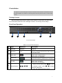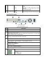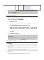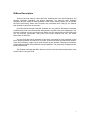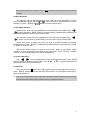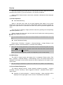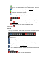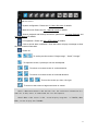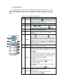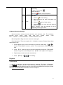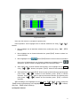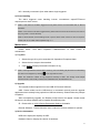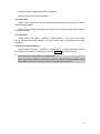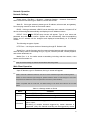
1
DVR User Manual V2.0 I About This Manual This manual is designed to assist customers in the use of the DVR developed by our company. Information in this document has been carefully designed and arranged, and also checked for accuracy before publication; however, no guarantee is given as to the correctness of the contents in print and depiction. Corrections will be made as necessary in subsequent editions for the benefit of our customers. No guarantee or other hints in any form about the content or usage of this manual is announced. Also, the information contained in this document is subject to change without any previous notice by function upgrade or addition. Edition 2.0 Apr 2009 No part of this documentation may be copied, reproduced, or translated in any form without the written permission of the copyright holder. II Before Starting Your DVR Operation This document is a basic manual for the DVR users. This manual describes the appearance of products, how to operate, how to configure the system program, and how to use the system. Before using DVR, a user should read the contents of this user manual, and then deal with the product considering the precautions defined in the manual. To open the DVR case and touch the inner parts for corrective maintenance, a user should contact the place where he/she purchased the products to get the help from expert. In addition, if there is any question for use or any damage on the product, please contact with the supplier who he/she purchased the products from. Precautions for safety 1. Precautions for installation Do not install it on a place that is exposed directly to the sunshine or contains lots of heat such as near a heating apparatus. Do not install it on a place where there is severe vibration, much humidity or soot. Install the product on a well-ventilated place. Install the product on a flat floor. The operating temperature range is 0℃~55℃. The operating humidity is 20%~90%. 2. Precautions for use Confirm that the DVR power supply input switch is positioned correctly for the local voltage before connecting and powering on the unit. Follow local rules for grounding the DVR and associated equipment. Confirm proper hard drive installation. III Table of Contents I INTRODUCTION...................................................................................................................... 1 BRIEF INTRODUCTION ...................................................................................................................... 1 MAIN FEATURES .............................................................................................................................. 1 II INSTALLATION ....................................................................................................................... 3 PACKAGE CONTENT ......................................................................................................................... 3 FRONT PANEL OPERATION ................................................................................................................ 3 REAR PANEL DESCRIPTION .............................................................................................................. 4 REMOTE CONTROLLER .................................................................................................................... 5 HARD DISK INSTALLATION ............................................................................................................... 6 REAR PANEL CONNECTION............................................................................................................... 6 III MENU DESCRIPTION ............................................................................................................ 8 MENU STRUCTURE .......................................................................................................................... 9 MENU OPERATIONS ......................................................................................................................... 9 IV OPERATIONS ........................................................................................................................ 11 TURN ON ....................................................................................................................................... 11 PREVIEW ....................................................................................................................................... 12 RECORD ........................................................................................................................................ 15 CAMERA CONTROL ........................................................................................................................ 16 PLAYBACK .................................................................................................................................... 18 BACKUP ........................................................................................................................................ 20 ALARM SETTINGS.......................................................................................................................... 20 MAINTENANCE .............................................................................................................................. 21 NETWORK OPERATION..................................................................................................... 23 NETWORK SETTINGS ..................................................................................................................... 23 WEB CLIENT OPERATION ............................................................................................................... 23 V APPENDIX ............................................................................................................................. 30 SPECIFICATIONS ............................................................................................................................ 30 METHODS OF CALCULATING HDD CAPACITY ................................................................................. 32 DEFAULT VALUES .......................................................................................................................... 33 I I Introduction Brief Introduction This Series DVR is 4-channel playback H.264 main profile stand alone DVR with Pentaplex function: record, playback, live preview, remote preview and backup supported. With professional and high performance intelligent audio & video solution, user-friendly GUI and practical industrial designs, this series DVR is quite suitable for civil applications such as home, stores, Internet bars and small offices besides the common security & surveillance applications. Main Features 1) Video/Audio Compression 4/8/16 channel PAL/NTSC/SECAM video signal input and H.264 compression standard with each channel being compressed independently in real-time CIF resolution. 4/0/0 channel audio signal input and G.726 compression standard with each channel being compressed independently in 24Kbps. Note : in this series DVR, 4ch DVR supports audio input, but no audio or 4ch audio in 8/16ch DVR Multiplex stream with audio & video synchronized and individual video stream supported. Four-level selection of record quality and self-defined bit rate and frame rate supported. Adjustable video parameters. Multi-area motion detection. OSD of channel name and time supported. 2) Recording Manual record and schedule record supported. The schedule record types include: timing, motion detection, alarm, motion detection & alarm. SATA hard disk supported. Backup and clip record files through USB flash disk, portable USB HDD, and USB CD/RW supported. 3) Preview and Playback Simultaneous output of VGA, TV, and S-Video. 1 Up to 4 channels playback in fast play mode, slow play mode, rewind and single frame forward supported. OSD of channel name and time supported. Status displaying of local record, alarm and motion detection supported. 4) Control Controlling of PTZ and dome supported. Setting and calling preset, sequence and track supported. 5) Alarm Local alarm (includes exception and motion detection) triggered handling supported. Alarm linkage: triggered record, linkage alarm output and linkage PTZ preset, sound alarm, report to alarm center. 6) Network TCP/IP supported. PPPoE supported. Dynamic access to IP address, Dynamic Host Configuration Protocol (DHCP) supported. DDNS supported Visit video files in DVR HDD through network neighborhood supported. Real-time preview, downloading and playback remotely through network supported. Controlling of PTZ, configuring device parameters, acquiring device status and logs, and upgrade remotely through network supported. Local recording through network supported. 2 II Installation This chapter is a general description of the device interfaces and connections. It describes the way of hard disk installation, the interfaces of the front panel and the rear panel for users to connect cables correctly. Package Content After purchasing DVR product, unpack it and unload it on a flat floor or a place where it is to be located, and refer to the “Package Contents” for counting device fittings. Front Panel Operation 1 2 3 4 5 Pic II-1Front Panel Table II-1 Front Panel Description NO. Type Name/Icon Description ① Interface UBS port USB 2.0 ② Numbers 1-16 Input numbers. One key channel selection from CH1 to CH16 in preview mode . Hard disk indicator. Green. Blinks when reading/writing. Black when non-operation. Event alarm indicator. Light when alarming, black when not alarming Remote Controller operation indicator. Green. Blinks when operating. Black when non-operation. HDD LED ③ Event LED IR LED 1. When in menu mode, press ④ Arrow Buttons , , , , to move to selection boxes, press , to select submenu parameters. 2. User can switch ActiveX on screen. 3 ⑤ 1. Press it to confirm operations in menu mode. 2. Press it to select record type in setting schedule. 3. Press it to change status of the current motion detection block. Press it to power on/off device. Hold pressing 3 seconds to shut down forcely. Power on/off Rear Panel Description 16CH DVR Rear Panel Pic II-3 Rear Panel Table II-2 Rear Panel Description NO. Description 16 CH DVR ① ② ③ Fan vent USB interface (Upper):USB2.0 USB interface (Lower): USB1.1 Support USB storage device, USB mouse, USB burner; Suggest USB 1.1 to connect USB mouse, USB2.0 to connect storage device. Video IN: 16 channel video input, BNC (1Vp-p,75Ω) AUDIO OUT: 4 ch audio ④ VGA : DIN-15 ( optional ) , 800x600@60Hz 、 800x600@75Hz 、 1024x768@60Hz 、 1024x768@75Hz、1280x1024@60Hz、1440x900@60Hz (optional); TV-OUT:1Vp-p, 75Ω; TV OUT: BNC ,1Vp-p,75Ω S-VIDEO:4-Pin SVideo,75Ω; VGA,SPOT output NET:RJ45,10/100M self-adaptive; USB Mouse:support USB mouse, plug and play; ⑤ ALARM OUT:1 channel switch-level alarm output,30VDC 1A,125VAC 1A; RS422 interface : for duplex operation of data transmitting and receiving TX+:transmit data TX-:transmit data 4 RX+:receive data RX-:receive data ALARM IN:4 channel switch-level input, N/O. or N/C. G:For ground connection ⑥ Power Input:AC110~220V Remote Controller Table II-3 Remote Controller Description 1 No Name 1 Power on/off 2 Adjust picture parameters 5 3 Function Buttons 6 2 7 3 8 4 9 4 Play control 5 Function Buttons 6 Numbers 7 Function Buttons 8 Arrow buttons 9 Function Buttons Fig II-1 Remote Controller Description Turn on/off the device, same as the button of front panel adjust brightness up/down, adjust contrast up/down record, same as the button of front panel. switch from single split to multiple splits view mode picture capture return to upper menu, same as the button of front panel stop , play in slow mode/fast rewind, play/pause , fast forward , go to previous section, go to next frame, go to next section CN/EN : Switch from Chinese to English, or reverse. × :Acknowledge alarm notifications, same as ○ the button of front panel. ID:Set ID of remote controller. Input numbers or select to switch among relevant channels. DEL:Delete FN:Auxiliaries, same as the button of front panel. The same as arrow buttons of front panel SET: Set parameters, same as the button of front panel. PTZ:Enable PTZ control, same as the button of front panel. 5 PROG:set sequence , PRESET:set preset, CALL:call preset, SEQ:call sequence, SCAN:Scan automatically Note: The following buttons are disabled currently: 【ID】、 【CN/EN】 、 【PROG】 、 【PRESET】 、 【CALL】 、 【SEQ】 、 【SCAN】 、 、 、 . Hard Disk Installation The hard disk is not included in factory fittings. Users can mount suitable hard disk by calculating its capacity referring to Appendix 5.2. Please follow these steps to install hard disk: 1. Open the DVR case. 2. Mount the 4 shock absorption washers into the clamping slots (four protruding steps) in the case. 3. Connect the HDD data cable and HDD power cable to HDD. 4. Attach the hard disk to the shock absorption washers by aiming installation holes to the case, hold and fix them by 4 M3*12 Head Screws plus plain washers. 5. Connect the HDD data cable and HDD power cable to the respond interfaces of main board. 6. Replace the DVR top cover. Note1: Please use the HDD special for DVR, and buy HDD from regular channels so that the quality can be guaranteed. Note2:Please format HDD for the first use, or system will sent error notification of “Hard disk error” accompanied with audio alarm. Please see 4.9 Maintenance for details. Rear Panel Connection 1) Power Input Connect power adapter to Power Input interface of DVR. Confirm that the DVR power supply input switch is positioned correctly for the local voltage before connecting and powering on the unit. Turn on the unit. The power LED will light if the power cable is connected correctly. Note: Please use the power adapter contained in the package. 2) Video Input The video input interface is standard BNC socket, 1Vp-p, 75 Ω. 6 Note: The video signal cable should keep away from the interference of strong electromagnetism and city electric field. 3) Audio Input The audio input interface is standard RCA socket, 2Vp-p, 600 Ω. Note: The audio input resistance is a little bit high; please use active sound collection device or active microphone. And the audio signal cable should keep away from the interference of strong electromagnetism and electric field. Note: 8/16 channel DVR has no audio function. 4) Network Input The network input interface is RJ45 10/100M self-adaptive. Note: Confirm that the network band width is enough for transmitting high definition image smoothly. 5) Alarm Input and Output The alarm input device should be the type of GND connected alarm or voltage input alarm, which can be set as N/O. or N/C. The requirement of signal input level for voltage input alarm type is: low level: 0~2V; high level: 5~15V. The green angle pins of signal cable are supplied for access of PTZ and alarming devices. Please follow these steps to connect: 1、Pull out the green angle pins that inserted in the alarm input and output interfaces. 2、Screw out the screws by micro Philips screwdriver, insert the signal cable into interface under spring, and then tighten the screws. 3、Plug in the connected pins into green angle pin socket. 6) PTZ Input Connect the PTZ control interface to RS422 TX+ and TX- interfaces of rear panel. The connection method is similar as above. Note: Please refer to PTZ manual for setting specific parameters, for some PTZ devices contain multiple telecommunication protocols, baud rates and IDs. 7) VGA/Monitor Input Video output interface: TV, VGA , S-Video (Spot for 16CH ) together simultaneously. . They can work 7 III Menu Description There are several ways to control the DVR, including the Front Panel Operation, the Remote Controller Operation, the Mouse Operation, PC terminal Client Software Operation and the Client IE Web Operation. Each control method allows you to operate the DVR conveniently. While some functions are controlled more easily by one method than another in particular environment. Front Panel and Remote Controller operation are very similar. Although the interface is different they both use similar button designations to perform the same operations. The Remote Controller is more convenient with which you can stand back from the DVR while you are entering commands. Using the Front Panel requires that you are within arms-reach of the DVR. You may find that mouse operation is the more convenient for local operation of the DVR. Mouse operation is intuitive for PC users. A left mouse click will select most options. From the live display a right mouse click will pop-up the Tool Bar. Selecting most options will be straight forward using traditional mouse operation. The particulars of operations are listed in the manual. This chapter describes the Menu Structure and most of the General Operations users will be used in using the DVR. 8 Menu Structure 语言/Language Video Standard Record Resolution System setting VGA Setting Time Format Time Setting Record setting Password Setting Record schedule Video quality Record frame rate Camera Channel PTZ Protocol Camera setting Video Channel Record source OSD setting PTZ Baud rate Network PTZ ID System IP address Color Setting Manual Record Subnet mask Motion Detection Network setting Playback Alarm setting Tool Bar PTZ Control Gateway HTTP port Alarm input channel Alarm input type Event Handling Command port Media port Log view Upgrade Clear Alarm Shut down Status Format HDD Maintenance HDD capacity Save & exit Save setting 4CH Alarm input 1CH Alarm output Exit Restore defaults Firmware version Software version Release date Lock screen Menu Operations 1) General Operations Press 【SET】 button to enter into system setting screen. Press 【●】 button to start/stop recording manually. Press 【 ‖】 button to play record file. Press【PTZ】 button to enter into PTZ control screen. Note: This manual indicates the Menu selection icons and selection boxes in <XX>; the buttons in 9 Menu screen (except menu selection icons) in XX; the buttons on front panel and remote controller in【XX】. 2) Menu Selection The highlight menu is the current active one. User can move highlight icon to the menu needed using 【▲】,【▼】,【 】,【 】 button, and press 【OK】 button to confirm selection, or press 【ESC】or button to return to upper menu. 3) Sub Menu Selection Selection box: User can move highlight icon to the selection box needed using 【 】, 【 】 button, and press 【OK】 button to confirm selection. Multiple items are allowed to be selected together at once by left clicking mouse. Sub menu list: User can move highlight icon to the sub menu needed using 【 】, 【 】 button. Or roll mouse to select directly. Only one item can be selected here. Edition box: when in edition box, user can type in numbers directly by pressing number buttons. Press 【DEL】 to delete the character before cursor and press 【OK】 or 【ESC】 button to exit. Sub screen button: Press it to pop up sub screen. When in sub screen, select “Confirm” to save configuration and return to the upper menu. Press 【ESC】 or select “Cancel” to return to the upper menu without being saved. 4) Screen Operation Use 【 】,【 】 to move highlight icon to any of the selection boxes. Press 【OK】 button to switch to another selection status. Use 【▲】, 【▼】 to specify the sub menu value where sub menu selections exist. 5) Save/Exit Exit: User can click × button on the right upper corner, or single right click mouse, or press 【ESC】 button to enter into the Save & Exit screen. You can select exit directly or exit after being saved. Note: There are three different ways to take effect: take effect instantly, take effect after being saved, and take effect after restarting device. Please refer to the navigation for details. 10 IV Operations This chapter mainly describes the main system operations of DVR. Please see the following contents for details. Turn on 1) Startup The Power LED will light after powering on correctly. Please refer to 2.6 Rear Panel Connection for details of connection method. Press 【Power on/off】 button to start up device., the login box will appear then. Please select proper user and type in relevant password to log in. Note1: It costs about 60 seconds to start up, please wait for a moment. Note2: Modify password by selecting <Tool Bar>→<System>→<System Setting>→<Password Setting>. Set as indicated, new password will take effect instantly. Note3: Default password for User is 666666; default password for Admin is 888888. Admin password can be restored to factory defaults by short-circuit the “JP 10” or “JP 15” on main board. The default password is 888888. User password can be reset by Admin via IE in ”User Management” Note4: The DVR will buzz and “NO Hard disk” appears when no hard disk in DVR. 2) System Settings Language: Please select <Tool Bar>→<System>→<System Setting>→< 语 言 /Language> to set language. VGA Resolution: Please select <Tool Bar>→<System>→<System Setting>→<VGA Resolution> to set VGA resolution and refresh rate. It supports 800×600@75Hz、800× 600@60Hz 、 1440 × 900@60Hz 、 1280 × 1024@60Hz 、 1024 × 768@75Hz 、 1024 × 768@60Hz currently. Please select relevant values according to the parameters of VGA. Date/Time: Please select <Tool Bar>→<System>→<System Setting>→<Time Format> to set time format. 12 hours and 24 hours are supported. Please select <Tool Bar>→<System>→<System Setting>→<Time Setting> to set date and time. Video Standard: Please select <Tool Bar>→<System>→<System Setting>→<Video Standard> to set video standard. PAL, SECAME, and NTSC are supported. Please select according to the parameters of camera. Note1: In order to avoid record files’ time confusion, you’d better stop recording before modifying system time. Note2: “Language” and ”Time” will take effect instantly. “Record Resolution” and ”Video Standard” will take effect after being saved. Note3: Users can refer to the navigations on the bottom of the main screen to look for relevant guides. 11 Preview After start-up system, the screen has live view area and tool bar. Right click mouse in preview mode or press on the front panel , the Tool Bar will appear. Videos, OSD of channel name, record time, and alarm notifications will be displayed on the screen. 1) Preview Operation View Mode Switching When in 4/9 splits view mode, the tile with highlight white border is the current selected one. User can use mouse or press 【Direction】 buttons to switch to another tile. If the audio output device is connected, the audio can also be previewed together with video. User can select to display a single particular channel by pressing the corresponding 【Numbers】buttons 1~8. When in single split view mode, user can enter into 4/9 splits view mode by pressing button directly, or reverse. Note: For 8 channel DVR, the view mode can be directly switched by tool bar. Please refer to 4.2.3 “Tool Bar” Image Parameters Setting Please select <Tool Bar>→<System>→<Camera Setting>→<Image Setting> to set brightness, contrast, hue and saturation. It will take effect instantly. Note1: User can set image parameters of one channel one time or all channels together at once by selecting All in <Camera Channel>. It is similar in other screen when user wants to set four channels together at once: select All in <Channel>. Note2: In preview mode, brightness, contrast can be adjusted by remote controller directly. 2) OSD Settings The OSD of channel name and system time is supported. Please select <Tool Bar>→<System>→<Record Setting>→<OSD Setting> to set. The channel name will be displayed on left upper corner and the channel time will be displayed on the righter corner of the screen. Note: After setting accomplished, the system time of OSD will be only added to record data stream. 3) Channel Status Display Area The channel statuses include: “motion detection triggered recording” / “common recording” /”motion recording”/ “alarm triggered recording” / “peripheral alarm input” / “alarm output”. Indication of “motion detection” / “common recording” / “alarm recording” will be displayed on the right upper corner of screen. The details are as follows: 12 indicates “motion detection”. The settings of motion detection include sensitivity and area selection. Please see 4.4.2 Motion Detection Settings for details. Blue indicates “common recording” Please see 4.3 Record for details. Green indicates “motion detection triggered recording”. Red indicates “alarm triggered recording”. Grey indicates “manual recording”. Indication of “peripheral alarm input” / “alarm output” will be displayed on system status column or Tool Bar. The details are as follows: : The four icons indicate the alarm input status. When alarming, it changes into red . Peripheral alarm input can trigger multiple events handling, please see 4.7 Alarm Settings for details. : the last icon indicates alarm output. When alarming outputs, it changes into . 4) Tool Bar Right click mouse or press 【OK】 button in preview mode, the Tool Bar shown as below will appear: : Hide the tool bar. : System configuration. Please see 3.1 Menu Structure for details. : Manual record. Please see 4.3.1 Manual record for details. : Search, playback and backup record files, please see 4.5 Video Playback and 4.6 Videl Backup for details. : PTZ operation. Please see 4.4.1 PTZ Control for details. : Click to cancel alarm notification. Click this button will pop a message to show the present alarm information. : Power off. : Alarm input and output notifications. 13 : Hide the tool bar. : System configuration. Please see 3.1 Menu Structure for details. : Manual record. Please see 4.3.1 Manual record for details. : Search, playback and backup record files, please see 4.5 Video Playback and 4.6 Videl Backup for details. : PTZ operation. Please see 4.4.1 PTZ Control for details. : Click to cancel alarm notification. Click this button will pop a message to show the present alarm information. : Power off. 、 、 :To set the preview mode of “Single image” ,“ Quad”,”9 image” :To adjust the screen, 8 pixels per unit can be adjusted. 、 :To reduce or increase screen in vertical direction. 、 :To reduce or increase screen in horizontal direction. 、 、 、 :To move the screen up, down, left, right :To zoom out the screen to largest and show in central. Note 1:When mouse moves to the tool bar icon, the indication information will come out to help users to understand the icon and operate. Note2:When video source is PAL, screen display range max. is 720*576;When NTSC,screen display max 720*480。 14 Record Record type contains manual record and schedule record. The priority of manual record is higher than schedule. If the record schedule is conflict with manual record, the manual record will be processed firstly until the manual record being canceled. Record types include “common recording” / “alarm triggered recording” / “motion detection triggered recording” / “alarm & motion detection triggered recording”. Each of them is indicated with grid of different color, and each color indicates a particular record status. Please see figure IV-3 record schedule for details. Record resolution: CIF Record quality: “Best 768Kbps” / “High 640Kbps” / “Better 512Kbps” / “Common 384Kbps”. And “User setting” can help user to set bit rate Record frame rate: if the current selection is PAL, the frame rate options are “All” / “12” / “6” / “3” / “1” / “Customized”. If the current selection is NTSC, the frame rate options are “All”/ “15” / “7” / “3” / “1” / ”Customized”. Default is “All”, 25 fps for PAL and 30 fps for NTSC. Record Resource: “Video” for video only or ”Video and Audio” and audio. for recording video Sub-stream: sub-stream can be enabled or disabled. After enabled, press 【ok】to set sub-stream, to set sub steam frame rate and bit rate. Sub stream frame rate rages from 1 to 15 frames, bit rate ranges from 32K to 512K. Note 1: Please refer to Appendix 5.2 for the methods of calculating HDD capacity. Note 2: Sub-stream for 8 or 16 channel DVR can only be set in 〖Advanced Setting〗. 1) Manual Record Please select <Tool Bar>→<Manual Record> to let the specific channel record or not. Press【●】 button to start/stop recording manually. NOTE1:The video recorded manually is named “common recording”. 2) Record Schedule Please select <Tool Bar>→<System>→<Record Setting> to set record schedule. The setting screen is shown as the figure below: 15 1 2 3 Fig IV-1 Record Schedule ①. ②. ③. The current recording channel number The record schedule Description of record type System provides a recording option for hours every day and Sun. through Sat. every week. Unit is hour. One grid indicates one hour. 1. Move highlight icon to a time grid using 【Direction】 buttons. 2. Specify the recording type by repeat pressing 【OK】 button or double left clicking mouse,(the color of the grid will change relevantly). 3. Select OK to confirm settings. The settings will take effect after being saved. Note1: User can copy the current setting onto the neighboring grid by pressing 【Fn】button first , 【Direction】 buttons secondly, and then the 【Fn】 button again to exit. Or user can drag mouse to set. Note2: When motion detection & alarm recording is selected, the motion detection sensitivity and area should be set ahead. Please refer to 4.4.2 Motion Detection Settings for details. When alarm recording is selected, the alarm triggering settings should be set ahead. Please refer to 4.7.2 Event Handling for details. Camera Control 1) PTZ Control PTZ Settings Select <Tool Bar>→<System>→<Camera Setting> to set camera channel, protocol, baud rate and ID. Note: The different PTZ controlled by one PCI should have corresponding PTZ ID. There are 16 PTZ ID supported currently: 0-15. 16 PTZ Operations In preview mode, select a tile first (in 4/9 splits view mode, the selected tile is with highlight white border) using mouse or 【Numbers】 buttons, and then select <Tool Bar>→<PTZ Control> to enter into the PTZ Control screen that described as the table below: Table IV-1 PTZ Operation Description NO. Name Description Click the arrow icons to control direction of PTZ. ① Direction ② Speed ③ Advanced ④ Focus ⑤ Iris 1 2 3 4 6 5 7 8 ⑥ Auxiliary ⑦ Zoom ⑧. Preset 9 10 Fig IV-2 PTZ Click the center icon to call sequence or run scanning. Please refer to the PTZ manual for details of PTZ scanning mode. Set the turning speed of PTZ camera. Click and to show/hide the advanced setting screen (the part under the button ). Click to focus-in and focus-out (it is disabled for cameras with automatic focus). Click to make the image brighter or darker (it is disabled for cameras with automatic iris adjustment). Open/close auxiliaries. Click to open and click to close. Different functions respond to different protocols. The auxiliaries include light, rain brash, and power etc. please refer to PTZ manual for details. NOTE: Up to 2 auxiliaries are supported on device side. Up to 4 auxiliaries are supported on client web side. Click to zoom in/zoom out (it is disabled for cameras with automatic focus). Preset is to set camera position, focus, zooming, and iris position, and then mark them in numbers for later calling. Up to 16 presets can be set currently. Set preset: 1. Select the preset number you want to name as. 2. Position the camera as desired position including direction, focus, iris and zoom value. 3. Click on the set button . call preset: 1. Select the preset number you want to call. 2. Click on the go-to button . Clear/reset preset: 1. Select the preset number you want to clear/reset. ⑨. Sequence 2. Click on the clear button . Sequence is a running route of camera that passes through multiple presets. Set sequence: 1. Select preset number you want to call. 2. Click on set button . 17 3. Repeat step 1 and 2 to add the other presets till finishing. 4. Click on run button Clear sequence: . Click on button to clear sequence. Track is a continuous running route of camera. Set track: ⑩. Track 1. Click on to start setting. 2. Move camera as the track and pattern you want it to run. 3. Click on again to finish setting. 4. Click on to run track and click again to stop running. NOTE: Whether Track is supported or not is depending on the type of PTZ. 2) Motion Detection Settings Motion detection settings include sensitivity and detection area. The sensitivity includes three levels: High, Mid, and Low. Please select <Tool Bar>→<System>→<Camera Setting>→<Motion Detection> to set. Mouse Operation: Drag mouse on screen to create grid. Panel Operation: There are totally 16 X 12 blocks in screen. Please follow these steps below to set: 1. Move highlight icon to one of the blocks you want to create using 【 】、【 】 buttons. Press【OK】 button to confirm. The created block will be in highlight blue. 2. Press 【Fn】 button to copy the current configuration, and press 【Direction】 button to copy to the relevant grid. Press 【Fn】 button again to exit copying. 3. Repeat steps 1 and 2 to set the second area. 4. Press 【ESC】 or to exit setting. Playback 1) File Search Specify the date/time and channel number by selecting <Tool Bar>→<Playback>. Click Search in the pop-up screen to start searching. The searching results will be list on the screen in responding different colors so as to distinguish different record types. Please see Fig4-1 Record Schedule for details of colors description. 18 Fig IV-3 File Search User can click mouse or use panel to specify time. Panel operation: move highlight icon to relevant selection box using 【 】,【 】 buttons. 1. Move highlight icon to date/time selection box, modify time using 【▲】,【▼】 buttons. 2. Move highlight icon to channel selection box, press【OK】 button to select it or cancel selection. 3. Move highlight icon to , press 【OK】 button to zoom in/zoom out timeline (time ruler). If the timeline is out of screen, please move highlight icon to and press 【OK】 button to display the part out of screen in order. 4. After setting time, channel number and timeline, move highlight icon to Search using 【 】,【 】 buttons, and press 【OK】 button to start searching. 5. After searching over, press 【Fn】 button to pop-up the timeline for selecting start point. Press 【 】,【 】 buttons to move timeline, press 【Fn】 to confirm selection. Press 【Fn】 again to pop-up the second timeline for selecting stop point, press 【 】, 【 】 buttons to move timeline, press 【Fn】 to confirm selection. After all settings, move highlight icon to Play using 【 】,【 】 buttons, and press 【OK】button to start playing. move highlight icon to Backup using 【 】,【 】 buttons, and press 【OK】button to backup. 2) Playback Control 19 :Fast backwards, the available fast backwards speeds are: 8X and 16X. :Pause the current play, or stop the current pause. :Stop playing. :Click to control speed of Forward, the available forward speeds are 1X, 8x 16x, 1/2X and 1/4X. :Go to next frame. :Click to switch from single split view mode to 4/9 splits view mode, or reverse. The status of playing will be displayed on the right upper corner of screen: Indication Speed 16X 16X fast forward 8X 1X 8X fast Normal forward playing 1/2X 1/2X forward 1/4X 1/4X forward 8X 8X fast backwards 16X 16X fast backwards Note: When playback only one channel, the image will display in full-screen. Backup Select <Tool Bar>→<Playback> to search, backup and playback the specific record files you needs. Click Backup to enter into the backup screen. System will detect all the backup devices available and display them. Please select the suitable device and record type according to requirement first, and click Backup to start storing. If there is no backup device found, a prompt tip will appear to remind users of connecting USB device well. Note: The record types include H.264 Raw and MP4. When backup in MP4 types, the special player plug will also be backed up into USB together automatically. After player plug is installed, the stored video files can be played by Windows Media Player. Alarm Settings Please make sure that the alarm input and output cables are connected correctly. Please refer to 2.6 Rear Panel Connection for details. Select <Tool Bar>→<System>→<Alarm Setting> to configure alarm parameters in the pop-up screen. Note: All the settings will take effect after being saved. 1) Alarm Input The alarm input attribution includes N/O. and N/C. Please select a suitable attribution according to the types of alarm device connected and control modes of alarm device adopted. N/O.: Normally open. Circuit connected when alarm single triggered. 20 N/C.: Normally connected. Open when alarm single triggered. 2) Event Handling The alarm triggered event handling include: record/alarm output/PTZ/sound output/report to alarm center. Note1: if user wants to set alarm triggered record, please set the record schedule first at “Record Schedule”. Note2: if user wants to set alarm triggered PTZ, please select the channel number first, and then to set (only preset 1 can be selected) Note: In 4channel DVR, event handling sound / report to alarm center need to be set in IE explorer. Please refer to 4.8.2 Web Client Operation Fig. IV-2 Maintenance Please select <Tool maintenance. Bar>→<System>→<Maintenance> to enter screen of 1) Log View 1. Select the type of log to be searched: All/ Operation/ Exception/ Alarm. 2. Select the time scope to be searched. 3. Click Searh to display the detail information of log. Note1: If the logs searched contains alarm event log, user can directly play the video recorded during the alarm event happens by clicking on the right side of screen. Note2: The maximum number of logs supported currently is 3000. The storage mode adopts overwrite mode: continuously overwrite the oldest data when the database is full. 2) Upgrade The upgrade modes supported now are USB/ IE/ Remote Software: USB:Please make sure the USB device is connected correctly and the upgrade applications have already being copied into USB root directory. Please follow the prompts to operate. After accomplishing upgrade, the Restart prompt screen will appear. Please restart the device, the latest software will be installed automatically then. IE:Please refer to 4.8.2.2 Device Parameters Settings for details. Remote Software:Please follow the user’s manual of remote software to operate. 3) Device Information HDD Size: display the capacity of HDD. Hardware Version: display the version of hardware. 21 Software version: display the version of software. Release date: for the current software. 4) Format HDD Please make sure that all of the important record files have already being saved before formatting HDD. Please stop all of the recordings in the beginning of formatting HDD. And follow the prompts to operate. 5) Lock Screen Please select <Tool Bar>→<System>→<Save Setting>→<Log Out>, the preview screen will appear together with the log-in box. Please type in the password for other operation. 6) Restore to factory defaults Please select <Tool Bar>→<System>→<Save Setting>→<Restore Defaults>, system will remind you of whether recovering or not. Click Confirm to process restoring. Note1: Please refer to Appendix VI for the default values. Note2: The system language, time, camera P/N system, and network settings (IP address, subnet mask, gateway, HTTP port ) will not be recovered by restoring to factory defaults. 22 Network Operation Network Settings Please select <Tool Bar>→<System>→<Network Setting>→<Network Connection>, there are three connection types: Static IP, DHCP and PPPoE. Static IP:If this type selected, please type in IP address, subnet mask, and gateway. User can ping network to check its connection status. DHCP:If this type selected, a DHCP server should be set in network. A dynamic IP of device will be assigned automatically and displayed on IP Address column. PPPoE:Click >>, the PPPoE setup screen will appear. Type in user name and password and click OK to confirm. System will dial automatically. After accomplishing dialing, the IP address will be assigned and displayed automatically on IP Address column. The following are types of ports: HTTP Port:It is the port number of browsing through IE. Default is 80. Signal Port:It is the first entry port for communication between web client and device, which is mainly used for controlling of log-in, log-out, real-time preview, remote playback, and remote download, etc. Media Port:It is for media stream transmitting including real-time stream, voice stream and file stream etc. Note: All of these settings of network will take effect after being saved. Web Client Operation Open IE browser, type in IP address, the log-in screen will appear. Note1: If PPPoE or DHCP is selected, user has to check IP address again after restarting device. Note2: If it is the first time login through IE, please install the Active X of IE and type in user name and password. Default user name and password are: Admin (case sensitive). Note3: Compared with the local side, the added settings on IE Web client side are as the table below: Table IV-2 Settings added on IE side Menu Contents Name of DVR is configurable on Web client side. <Server> Enable PPPoE, the DNS address is configurable. The address and port of host PC is configurable. <Channel> Motion detection can trigger audio alarm, remote notification and alarm output. Recording of multiple channels triggered by motion detection is supported. (Only one channel recording can be triggered by motion 23 detection on local side.) The event handling of video lost is selectable: audio alarm, remote notification and alarm output. <Alarm> The event handling of alarm input is selectable: audio alarm, remote notification and alarm output. Multiple channel recording triggered by alarm input is supported. <Device> User can adjust DVR time accordance with PC time. <State> Device states can be viewed directly. PTZ Support up to 2 auxiliary channel on local side and 4 auxiliary channel on IE side: 1、2、3、4。 1) Web Screen Description Fig IV-4 Web Screen Address:Display the DVR IP address. Tool Bar: The description of icons from left to right is: Configure device parameters. Search and playback record files. View logs and export them. Set the storage directory of record files. Click to switch image view modes among full-screen, single split view mode and 4/9 splits view mode. 24 Log-out, restart device, Clear alarm Alarm Notification: When network connection is broken or abnormal, the alarm notification of “No heartbeat of device, please check the network!” will be displayed in the right up side of the main screen. After recovery of network, the preview will be displayed automatically. When alarms of remote notification occur, the alarm notification with alarm input number contained such as “Device alarm: IO alarm, IO input x” will be displayed in the right up side of the main screen. When alarms of motion detection with remote notification occur, the alarm notification with the alarm channel number contained such as “Device alarm: motion detection, channel 1” will be displayed in the right up side of the main screen. When alarms of video loss with uploading to center occur, the alarm notification with the alarm channel number contained such as “Device alarm: video loss, channel x” will be displayed in the right up side of the main screen. Preview , :Adjust image contrast up/down. , :Adjust brightness up/down. :Start/stop voice monitoring. The icon will turn to green when recording. :Start/stop recording. The icon will turn to green when recording. :Click to snapshot. :Stop preview. Note: Click to set the storage directory of record files and pictures captured. PTZ Setting The PTZ setting of client web is similar as the PTZ operation of local device, please refer to 4.4 Camera Control. Note: Our DVR supports 4 auxiliaries on IE side. 2) Device Parameters Settings Click , the parameters configuration screen will appear. All of the configurations are divided into the following six selections: <Server> It includes the configuration of server, network, PPPoE, and version information. All of these configurations except PPPoE can be set in <Tool Bar>→<System>. 25 PPPoE: it is to set the information of registering to central management software. It includes server address, port number and intervals of registration. Note1: If the DHCP mode selected, the IP address is assigned automatically without being modified. Note2: DVR-this series DVR does not support DNS mode currently. <Channel> User can set motion detection, video loss, OSD, image bit rate and frame rate, image parameters and record schedule here. Note: User is allowed to set single channel first, and then to copy the settings to the other channels. <Serial> User can set PTZ protocol, baud rate, and address code here. All of these settings can be done by selecting from <Tool Bar>→<System>→<Camera Setting>. <Alarm> User can set IO alarm and event handling here. All of these settings can be done by selecting from <Tool Bar>→<System>→<Alarm Setting>. <User Management> Including user authority and password setting. Relevant interface information should be <Tool Bar>→<System>→<System Setting>→<Advanced Setting> . “User” authority and password can be changed by “Admin”, <Device> Upgrade:Click Browse to select the software package needed, and click Start Upgrade to progress. User can stop the progress of upgrade by clicking Stop Upgrade. Adjust Time:Click Adjust Time to adjust time of device accordance with the PC time. <State> The information of HDD and channel state is contained here. 3) Playback Click download. , the playback screen will appear. It includes file search, playback and File Search The file search part is on the right upper side of the screen, please set target, type, start time and end time there. Then click Search to start searching. The result will list on the table. Specify the files in the table list and click on the playing control button or download button to do the relevant operations. 26 File Playback The play control screen is on the left side of the screen. It includes image display area, play control bar, and channel information. Click Play, the record files selected will be displayed in time order. The progress of playing is shown as the figure below: The playing control bar is shown as the figure below. The descriptions of all these icons from left to right are as follows: Play; Pause; Stop; Go to next frame; Fast play option (The speed of playing will be doubled by each clicking. It includes: 2X, 4X, 8X, and 16X); Slow play option (The speed of playing will be half down by each clicking. It includes 1/2X, 1/4X, 1/8X, and 1/16X); Enhance contrast; Reduce contrast; Enhance brightness; Reduce brightness; Open/close voice; Go to previous file; Go to next file ( and is enabled only when multiple record files being selected to play); Snapshot (the storage directory can be set on the pop-up screen by clicking ). The information of the record file selected will be displayed in the area shown as the figure below. It includes device’s IP address, current play speed, channel number and start/end time of the record file. File Download The File download operation part is on the right bottom of the screen. Click to set the storage directory of the file selected. Click Download to start downloading. 4) Log Click , the screen of device logs will appear. There are four options for choosing: All, according to time, according to type, according to time and type. To search logs, please select the search mode and channel number needed first and then click Search to progress. Click Export to export logs in html format. 27 5) Remote Upgrade Select <Server>-<Manage>, click Browse to specify the file for upgrade, and click Start to upgrade. User can click Stop to stop upgrading in progress. 6) Advanced Setting Note1: This setting is just suitable for 8 CH DVR. Advanced setting of 4 channel DVR need be done in IE explorer. Note 2: Advanced setting requires the user to have enough authority. Please use “Admin” to log in and run advanced settings. <User Management> Enter <Tool Bar>—<System>—<System Setting>—〖Advanced Setting 〗, select 〖Authority Management〗 to enter the authority setting page for “User” Authority setting includes local and remote authority setting, as the following figure. Fig.4-7 Authority Setting Interface When operation in front panel, Use direction【Up/Down/Left/Right】button to move focus the relevant authority, press【OK】to select or double press【OK】to cancel the item. After selecting, press direction 【Up/Down/Left/Right】 to position of【OK】 or 【Cancel】 to exit with or without save. When operation with mouse, just click mouse to choose proper authority and click 【OK】 or 【Cancel】to exit with or without save. <Camera Setting> Enter <Tool Bar>—<System>—<Camera Setting>—〖Advanced Setting 〗 to set camera 28 <Motion Event Handling> When motion event happens in special area, motion event handling can be set : triggered recording / triggered alarm output / sound Alarm / Report to Alarm Center. Not: Sensibility setting can be referred to 4.2.2 “Motion Detection Setting” Video Loss When video loss in selected channel, event upon video loss can be handled : Triggered alarm output / sound alarm / Report to Alarm Center. § 1.1.1 Network Connection Enter <Tool Bar>—<System>—<Net >—〖Advanced Setting 〗 Set PPPOE Select to activate PPPoe, click 〖>>〗, enter PPPoe user name and password input interface. After right information input, DVR will dial automatically. After successful dial, auto accessed IP address and relevant information will appear on DVR. Set DNS Server Address DNS server IP address information is required to type in. Set Dynamic Domain Name Select “Activate Dynamic Domain Name ”, click 〖>>〗to configure dynamic domain name. Select a special kind of domain name server, type in Dynamic Domain Name address, user name and password. Note : Presently 6 kinds of dynamic domain server are included in this DVR Auto Register Setting Select to activate Auto Register function, click 〖>>〗 to Auto Register interface, management host IP address, host port, register interval time is required to input. File Sharing Check to activate file sharing function, then able to visit video files in DVR HDD via network neighborhood How to visit shared files: Double click network neighborhood, input \\ IP address, such as \\192.168.10.220 , to enter the login page, type in the super authority “Admin” and password, the shared files can be accessible now, click into folder of “videoout” to check video files. Note:After player plug is installed, video files can be played by Windows Media Player. 29 V Appendix Specifications Table V-1 Specifications DVR Type 4 channel DVR System Video Input Audio Input VGA Output 8 /16 channel DVR Linux 2.6 O/S Pentaplex operation: record, playback, preview and network browse, backup supported. 4 channel, BNC, 1Vp-p,75Ω 8 channel, BNC, 1Vp-p,75Ω PAL (625 line, 50 f/s), NTSC PAL (625 line, 50 f/s), NTSC (525 line, 60 f/s), (525 line, 60 f/s), SECAM(625 SECAM(625 line, 50 f/s) line, 50 f/s) 4 channel, RCA, 2Vp-p , 0/4 ch audio 600Ω 1 channel, DIN-15(optional); 800x600@60, 800x600@75, 1024x768@60, 1024x768@75, 1280x1024@60, 1440x900@60 CVBS Output 1 channel, RCA, 1Vp-p,75Ω 1 channel, BNC, 1Vp-p,75Ω S-Video Output Audio Output 1 channel, 4-Pin S-Video, 75Ω USB Interface 1 USB port (USB2.0 High-Speed 480Mbps) in rear panel for USB flash disk, USB mouse, portable USB HDD, USB CD-RW PS2 Interface 1 port for PS2 mouse, plug and play RS422 1 port, receiving and transmitting duplex supported. Network Interface Alarm Input RJ45 Alarm Output 1 channel NO/NC, relay: 30VDC 1A,125VAC 1A SATA Interface 1/2 SATA Port ,support 1X1T /2X1T SATA HDD Video Compression H.264 Main Profile I/O Interface 1 channel, 600Ω RCA, 2Vp-p, 0/4 audio 2 USB port. 1 port USB1.1,1 port USB 2.0 in rear panel. Support USB storage device, USB mouse, USB burner. USB 1.1 is recommended for mouse, USB 2.0 for USB storage device. No 10/100M self-adaptive 4 channel NO/NC Video & Audio Video 30 Video Standards Video Compression Resolution Frame Rate Video Output Bit Rate Audio PAL/NTSC/SECAM PAL:352×288(CIF)NTSC: 352×240(CIF) PAL:25F/S/CH 1,3,6,12,25 and user-defined optional; NTSC: 30F/S/CH 1,3,7,15,30 and user-defined optional. 32kbps-2048kbps(14M byte/hour - 922M byte/hour) Preview Resolution Playback Resolution Audio Compression Input/Output Sampling Rate Audio Channel Type PAL:720×576(D1) ,horizontal line 550, vertical line 450 NTSC:720×480(D1) ,horizontal line 550, vertical line 400 PAL: 352×288(CIF) ,horizontal line 300, vertical line 250 NTSC: 352×240(CIF) ,horizontal line 300, vertical line 220 Sampling Bit 16 bit G.726 ADPCM 8KHz Mono Main Functions Operating Interface Record Playback Backup Network Log Operation PTZ Control Multiple control methods: mouse, IR remote controller, front panel and GUI with navigation supported. Multiple languages: Traditional Chinese, Simplified Chinese and English supported. Some other languages supported after upgrading. Recording status and alarming status can be displayed directly on desktop and front panel. Five recording modes: Manual, Schedule, Motion Detection, Alarm, and Motion Detection & Alarm supported. Selectable Record Quality: Best, High, Mid, Low and User-defined. Play progress bar supported. Multiple channel video/audio playback simultaneously. Play, pause, stop, single frame forward, fast forward and backward (up to 4/9ruple when playback 4 channels) supported. Multiple backup modes: USB flash disk, USB HDD, USB CD-RW, and DVD-RW supported. The output format can be H.264 RAW. IPv4, PPPOE client, DHCP client and TCP/UDP protocol supported. The Web Client and Client Application Software are provided for remote configuration, video browse, local recording, local and remote playback, and remote PTZ control. Network transmitting supports independent coding. The time delay of LAN is less than 300ms. The log of operation and alarming will be saved automatically. User can directly play the record files that being record when the alarm event occurs. Multiple protocols: Pelco-P, Pelco-D, and Samsung, etc. supported. Upgrade of protocol supported. Multiple PTZ operations: Pan, Tilt, Zoom, Preset, Sequence, 31 Track and Auxiliary Switch supported. Alarm Management Account Management Auxiliary Function Environmental Power Supply Operating Temperature Operating Humidity Power Consumption Dimension 4 channel alarm input NO/NC supported. Motion detection and alarm of video loss supported. Trigger recording, Linkage PTZ preset and Bee alarm supported. The alarm information can be sent to Web Client or Client Application Software through network. Dual account supported. Users can set & recover password, authentication management. Hardware Watch Dog supported. Device will be restarted if operations being not responded for 30 seconds or more. DC 14-19V 3A,positive inside, negative outside, power adapter is connected outside. 0℃-+50℃ 10%~90%RH <12W(without HDD) 1U /1.5U Methods of Calculating HDD Capacity 1) Calculate the maximum capacity of the build-in hard disk. Timing Recording: Step 1: Calculate the maximum capacity of the hard disk needed in selected channel per hour, suppose as Si (MByte) (i is the channel number), and suppose the bit rate of the channel selected as D (Kbit/s). The formula of calculation is: Si =(D*3600)/(8*1024)= D * 0.439453125 MB Step 2: Confirm the storage time length, suppose as T hours. The total maximum capacity of the hard disk needed in selected channel for T hours, suppose as St is: St = T * S1 Step 3: Confirm the total numbers of the channels, suppose as n. The total maximum capacity of the hard disk needed, suppose as Sc is: Sc = S1 + S2 + … + Sn Alarm Recording: Suppose the rate of alarming as α%. The capacity of the hard disk needed in alarm recording supposed as Sa is: Sa = Sc * α% 2) Calculate the compression bit rate for recording T hours. Timing Recording 32 Step 1: Suppose the capacity of the hard disk as S, the total numbers of the channel as n. The capacity of hard disk needed per channel supposed as Di is: Di = S / n Step 2: Suppose the total recording time as T hours. The capacity of the hard disk needed per hour per channel supposed as Dt is: Dt = Di / T Step 3: The bit rate of all the channels supposed as Dc is: Dc = Dt *(8*1024)/ 3600 = Dt * 2.2756 (Kbit/s) Alarm Recording Step 1: Suppose the rate of alarming as α%, capacity of hard disk as S, the total numbers of the channel as n. The capacity of hard disk needed per channel supposed as Di is: Di = (S / n) * α% Step 2: Suppose the time length of recording as T (hours). The capacity of hard disk needed per hour per channel supposed as Dt is: Dt = Di / T Step 3: The bit rate of all channels supposed as Dc is: Dc = Dt *(8*1024)/ 3600 = Dt * 2.2756 (Kbit/s) Default Values Menu 语言 System Settings /LANGUAGE Video Standard Record Resolution Table V-2 Default Values Options in menu Default 繁体中文、简体中文、English English PAL、NTSC、SECAM Auto adjust CIF CIF 800×600@75Hz、800×600@60Hz、 VGA Setting 1440×900@60Hz、1280×1024@60Hz、 1024×768@75Hz、1024×768@60Hz Record Settings 1024x768@60 Hz Time Format 12 hours,24 hours 12 hours Password Setting Click into sub menu screen. Record Schedule Click into sub menu screen. Video Quality Best, High, Better, Common Admin:888888 User:666666 24 hours Common recording High Record PAL:All, 12, 6, 3, 1, Customized All 33 Frame Rate NTSC:All, 15, 7, 3, 1, Customized SECAM:All, 12, 6, 3, 1, Customized Record Resource OSD Setting Sub-stream PTZ Protocol PTZ Baud Rate PTZ ID Color Setting Camera Settings Network Settings Alarm Settings Motion Detection Motion Detection Event Handling Video Loss Handling Video, Video & Audio Video & Audio Channel name, Channel name and time, time, none Frame rate and bit rate can be set: Frame rate:1-15 frame/second Bit rate: 32-512 Channel name and time Deactivated Frame rate:15 Bit rate:288 Pelco-P、Pelco-D、Samsung、Panosonic、 LILIN Pelco-P 1200、2400、4800、9600 2400 Click into sub menu screen. 1 brightness, contrast, hue and saturation : 8\8\8\8 High Sensitivity, Medium Sensitivity, Low Sensitivity Triggered alarm, alarm output, sound, report to alarm center 8\8\8\8 Medium Sensitivity Triggered recording current channel Alarm output, sound, report to alarm center Deactivated Network Static IP、Dynamic access of IP、PPPoE Static IP IP Address Subnet Mask Gateway HTTP Port Command Port Media Port Click into sub menu screen. Click into sub menu screen. Click into sub menu screen. Click into sub menu screen. 192.168.0.10 255.255.255.0 192.168.0.1 80 Click into sub menu screen. 5050 Click into sub menu screen. DNS address Click into sub menu screen. 6050 202.103.264.6 8 Dynamic Domain Name Auto Register File Sharing Alarm Input Type Event Handling Click into sub menu screen. Deactivated Click into sub menu screen. Click into sub menu screen. Deactivated Deactivated N/O. N/C. N/O. Trigger record, Trigger alarm output, Sound alarm,Trigger PTZ preset Trigger output sound alarm and 34 35