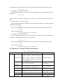
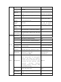
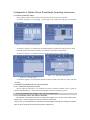
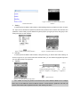
1
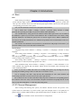
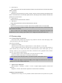
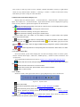
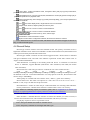
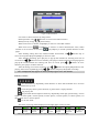
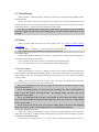
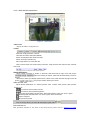
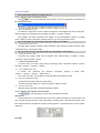
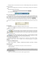
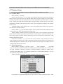
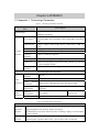
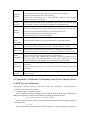
TS9004A Embedded
NVR
USER MANUAL
Ver 1.1
Contents
CHAPTER 1 PRODUCT INTRODUCTION .......................................................................................4
1.1 PRODUCT OVERVIEW.....................................................................................................................4
1.2 MAIN FUNCTIONS ...........................................................................................................................4
CHAPTER 2 INSTALLATION INSTRUCTION .................................................................................6
2.1 CHECK DEVICE AND ACCESSORY ..................................................................................................6
2.2 PANEL INTRODUCTION ...................................................................................................................6
2.3 REAR PANEL DESCRIPTION ...........................................................................................................6
2.4 INSTALLATION METHOD OF HARD DRIVE .......................................................................................7
2.41 Steps of Install Hard Drive...................................................................................................7
2.5 DEVICE WIRING DESCRIPTION ......................................................................................................7
CHAPTER 3 MENU DESCRIPTION ..................................................................................................9
3.1 MENU NAVIGATION .........................................................................................................................9
3.2 MENU OPERATION .........................................................................................................................9
CHAPTER 4 INTRODUCTIONS ....................................................................................................... 11
4.1 BOOT ............................................................................................................................................ 11
4.2 IP CHANNEL MANAGEMENT ......................................................................................................... 11
4.3 PREVIEW SETUP ...........................................................................................................................12
4.3.1 Channel Video Preview Area ...........................................................................................12
4.3.2 System Status Bar.............................................................................................................13
4.3.3 Toolbar.................................................................................................................................13
4.4 RECORD SETUP ...........................................................................................................................14
4.41 Manual Record....................................................................................................................14
4.4.2 Record Schedule Setup....................................................................................................15
4.5 CAMERA CONTROL ......................................................................................................................15
4.5.1 PTZ Control ........................................................................................................................15
4.6 DATA PLAYBACK ...........................................................................................................................17
4.7 DATA BACKUP ..............................................................................................................................19
4.8 ALARM ..........................................................................................................................................19
4.8.1 Alarm Input .........................................................................................................................19
4.8.2 Alarm Linkage ....................................................................................................................19
4.8.3 Alarm Defense and Plan...................................................................................................19
4.8.4 Device Exception Action...................................................................................................19
4.9 NETWORK CONNECTION ..............................................................................................................20
4.9.1 Network Setup....................................................................................................................20
4.9.2 Web Client Operation........................................................................................................21
4.10DEVICE MAINTENANCE ...............................................................................................................24
4.10.1Log View ............................................................................................................................24
4.10.2Upgrade Software.............................................................................................................24
4.10.3Device Information ...........................................................................................................25
4.10.4HDD Manage ....................................................................................................................25
4.10.5USB Manage.....................................................................................................................25
4.10.6Auto Maintain ....................................................................................................................25
4.10.7Boot Guide.........................................................................................................................25
4.10.8Logout User.......................................................................................................................25
4.10.9Restore the factory setting ..............................................................................................25
4.11SYSTEM SETUP ...........................................................................................................................26
4.11.1 System Menu ...................................................................................................................26
4.11.2User Management ............................................................................................................26
4.11.3Sub Stream........................................................................................................................27
4.11.4Video Advanced Setup.....................................................................................................27
CHAPTER 5 APPENDIX ....................................................................................................................28
5.1APPENDIX 1: TECHNOLOGY PARAMETER .....................................................................................28
5.2 APPENDIX 2: METHODS OF CALCULATING HARD DRIVE CAPACITY MOUNT IN NVR (FOR YOUR
REFERENCE).......................................................................................................................................29
5.3 APPENDIX 3: SYSTEM DEFAULT INFORMATION............................................................................30
5.4APPENDIX 4: MOBILE PHONE SURVEILLANCE OPERATING INSTRUCTIONS .................................33
5.4.1Server (miniNVR) Setup ....................................................................................................33
5.4.2Install Client (Mobile Phone Client) Software .................................................................33
CHAPTER 1 Product Introduction
1.1 Product Overview
This Product is quadruplex embedded NVR product, integrated video and audio
preview, record, playback and network access. Receive digital video stream from IPC
(network camera), DVS (video encoder) and other devices and have preview, store and
playback, centralize management functions. Take advantage of distributed architecture
and modularization access.
This Product use professional and high-performance intelligent video and audio
decoding solution, integrality concise and elegant user interface and useful industrial
design. Meet requirements of industrial security user and suit for consumer applications,
such as family, store, Internet bar and small office.
1.2 Main Functions
Front-end Device
¾
Support network sonar of 720P-IPC ;
¾
Support bindings connections of 720P-IPC;
Decoding
¾
Support input four channels code flow of 720P-IPC;
¾
Support forwarding four channels code flow of 720P-IPC;
¾
Compress video and audio signal to generate composite code stream, video and audio
synchronization. Can only record video stream;
¾
Receive IPC record parameter of front-end device, support custom setup code rate and frame
rate;
¾
Support adjust video parameter;
¾
Support OSD overlay channel name and time;
Video
¾
File record contains manual record and plan record, plan record can setup multiple record file
types: schedule record, , alarm record;
¾
Built-in SATA hard drive interface, support SATA hard drive;
¾
Support USB device(USB flash disk, USB mobile hard drive, USB CD/DVD RW, etc) to backup
and cutting video information in hard drive;
Preview and Playback
¾
Support single channel preview and playback with HD720P resolution, four channels 360P
video preview;
¾
Support single channel playback pattern, playback pattern such as: fast forward, slow, fast
backward and go to next frame;
¾
Support OSD overlay, channel name overlay;
Alarm
¾
Local Alarm Linkage(exception event,, video lost and hard drive full);
¾
Alarm Linkage: record, alarm out linkage, linkage PTZ preset, linkage channel frame zoom out
display, buzzer, upload alarm center, E-mail and upload picture via FTP;
Network Function
¾
Support TCP/IP protocol;
¾
Support PPPOE protocol;
¾
Support DHCP address(DHCP);
¾
Support DDNS;
¾
Support access hard drive’s video file through network neiborhood;
¾
Realize network video real time preview, remote video file download and remote video file
playback through IE plug-in module;
¾
Realize network , remote configure device parameter, get device running status and log
information and remote upgrade through IE plug-in module;
¾
Realize local video through IE plug-in module;
If there are any discrepancy found between product and attached pictures
in specification, all product-based.
Chapter 2 Installation Instruction
2.1 Check Device and Accessory
When you receive our product, please refer to “container list” that comes with packing
box to check device and accessories.
2.2 Panel Introduction
Figure 2-1
Type
Name
Indicator
Light
Panel buttons description
Description
POWER
Power Light: green, on when plug in
HDD
Hard drive indicator light, green, light flicker when hard drive
in read and write status, off means in other status.
Numeric
Key
0-9 numeric key:
1. Input number;
2. One key channel switching in preview mode.
Button
Function
Key
FN(use with numeric key 0), auxiliary function key:
1. In preview and playback mode, realize single channel,
multi-channel switching;
2. Press it to set play start time and end time in Record Search;
ESC: Return or exit to menu mode.
Control
Button
Direction
Key;
[▲],[▼]
[ ],[ ]
It consist of four buttons:
1.Use [ ],[ ] button to move menu setup action bar in menu
mode, use[▲],[▼]button to select data in menu setting;
2. Switch ActiveX on screen.
1.Make sure the operation in menu mode;
2.Select record type in record plan table.
2.3 Rear Panel Description
Figure 2-2 rear panel interface description
Order
1
Interface
Description
VGA output
1*DIN-15 socket
Alarm input
Four channels on-off input
Alarm out
One channel on-off output
Network
Interface
1*RJ45 10/100M, self-adaption
USB Interface
2*USB 2.0 interface, postposition 2*USB interface
3
RS485
1* data receive and send half-duplex interface(±)
4
Power supply
DC 12V 4A
2
2.4 Installation Method of Hard Drive
The hard drive is not included in factory fittings. Users can mount suitable hard drive by
calculating its capacity referring to “Appendix 2 in section 5.2: Methods of Calculating Hard
Drive Capacity Mount in NVR (for your reference)”.
2.41 Steps of Install Hard Drive
1
2
3
4
5
Open the roof cover of chassis, take out vibration washer in screw bag, Mount the four
vibration washers into the clamping slots (four protruding steps) in the chassis;
Connect SATA data cable and hard drive power cable to hard drive;
Turn the chassis and hold up the hard drive, aiming the four holes in rear of chassis to the
installation holes of hard drive; Fix them by four head screws(M3*12) and one plain
washers.
Connect SATA data cable and hard drive power cable to rear panel;
Close the cover of chassis and fix it by screws.
Note 1(Hard drive purchase on selection): Please choose hard drive that is recommended by hard drive
manufacturer and dedicated for video surveillance to meet requirements of long time and large capacity
read-write. Please buy hard drive from regular channels to make sure its quality.
Note 2: After installing hard drive, format the hard drive first before use it. Method of format hard
drive please refer to “4.10 Device Maintenance” for details.
2.5 Device Wiring Description
Power Input
Make sure alternating voltage is match with the requirements of power adapter then connect
power supply interface to adapter. If power indicator light is on means power input normally.
Note: Please use the power adapter that comes with NVR, avoid to damage device.
Access Network
Device offers standard RJ45 interface, you can access it into LAN or WAN easily. You must offer
adequate bandwidth in network connection to make sure network video transmission’s fluency and
clarity.
Alarm input/output device
Alarm input device need use GND input alarm or voltage input alarm type, support N.O. or N.C.
alarm type.
Requirements of voltage alarm signal input level: low level range: 0~2V, high level range: 5~15V.
Device offer “bent pin plug” to access PTZ and alarm device, steps of wiring:
1. Dial-out bent pin plug;
2. Use micro crosshead screwdriver to unscrew the screw in plug, connect signal cable to spring
lamination which in plug and tighten the screws;
3. Input the connected pin plug into the corresponding bent pin plug.
Output video device: Display/Monitor
Chapter 3 Menu Description
3.1 Menu Navigation
Figure 3-1 menu navigation of product
3.2 Menu Operation
Press [SET] key to enter Setting interface.
Press [●] key to enter manual record setup interface.
Press [ ‖] key to enter playback record file interface.
Press [PTZ] key to enter PTZ control interface.
Move or Select Menu
Main Menu has highlight rectangle box call “focus menu”. Use[▲],[▼],[ ],[ ]key to move
menu between focus, enter focus menu or execute focus operation please use[OK]key, return to
upper menu use[ESC]key.
Menu Item Type
Choice Box: offer multiple options, use [ ], [ ] to switch options, press [OK] key to make
sure choose this option, you can use mouse to choose one or multiple options.
List Box: offer multiple options but you can only choose one option, use [ ], [ ] key to
choose one option in multiple options or use mouse pulley to slide in list box.
Edit Box: offer a numeric keyboard rectangle box to enter edit status, you can directly input
number or use [▲], [▼], [ ], [ ] key to move the cursor location, confirm input. Use [DEL] key
to delete character before cursor; Press [OK] key or [ESC] key to quit editing status.
Button: execute current functions or enter next level menu. In next level menu,
press[Enter]key to save setup parameter and return to upper menu, press[ESC]key or[cancel]key
to quit setting parameter and return to upper menu.
Interface operation
Use [ ], [ ] key to switch focus in display item, use [OK] key to modify button operation,
switch option status. Use [▲] or [▼] to switch option value when choice box exists.
Quit/Save
Quit Interface: quit current interface by click the “ ” key in top right corner/click the right
mouse button or press [ESC] key. Enter<Toolbar>→<Setting>→<Save > after quit setup interface,
please choose quit directly or quit after saving the modified setup.
Note: After modifying menu setup, you can choose “with immediate effect” or “take effect after being
saved”. Please refer to specific setup information.
Chapter 4 Introductions
4.1 Boot
Boot
Finish Wiring according to “section 2.6 Device Wiring Description”. After finishing wiring,
power indicator light in panel turns to green, press [on/off] key to start up device, system will
enter preview interface and at the same time pop up login window, choose user and input the
corresponding password to enter system.
Note 1: It takes about 60 seconds to boot system, please wait a moment.
Note 2: Please enter <toolbar>→<Setting>→<System>→<password setting> interface to modify
password, after operating successfully, new password will take affect immediately.
Note 3: Default factory setting password for admin is 123456, default password for User is 123456. If
lose admin user’s password, you can short circuit terminal of “JP1” on main board to restore factory setting
password. Admin user can modify the password for User. Device support 8 users, admin is administrator
user and you can’t modify and delete the user. Admin has all permissions and can add and delete other users
and their permissions.
Note 4: If there is no hard drive when system boots, system interface will prompt “no hard drive”, you
can choose whether to buzz or not when there is no hard drive.
System Setup
Language Setup: Enter<Toolbar>→<Setting>→<System>→<Language> interface to setup
language.
VGA setting: Enter<Toolbar>→<Setting>→<System>→<VGA Setting> to setup resolution
and
refresh
rate
for
monitor,
support
800×600@60Hz,1024×768@60Hz,1280×1024@60Hz,1440×900@60Hz. Please choose suitable
value according to the monitor you have.
Time Setting: Enter<Toolbar>—<Setting>→<System>→<Time Format>,setup time display
format(12 hours or 24 hours)and setup specific time value.
Video Standard Setup: Enter<Toolbar>→<Setting>→<System>→<Video Standard> to set
video standard, only support PAL and NTSC. Please choose the suitable value according to the
video standard parameter.
Note 1: If you want to modify time when it in recording status, please stop recording first. Restore
recording after finishing setting to make sure that time of record file is correct.
Note 2: “Language” and “time” setup will take effect immediately, if want “video standard” and
“VGA setting” take effect, you need to choose [save] before quit interface.
Note 3: When focus move in menu, information will prompt below interface for corresponding option to
learn interface menu more easily. In the meanwhile, navigation information will prompt that the current
setup is “take effect immediately” or “take effect after being saved”.
4.2 IP Channel Management
After booting and entering into system, surveillance interface divide into preview area,
system status bar and toolbar, in preview mode, right click through mouse or use [OK] key in
panel will show toolbar. Hide toolbar by right click through mouse in toolbar or click left arrow.
Click
button in toolbar to enter front-end device configuration.
¾
Detect Device
Click to add device, enter into add new device interface, show the 720P-IPC front-end device which
detect in network.
¾
Add Device
Choose the front-end device you need to connect, enter the correct username and password and
bind it to channel of NVR or choose other specific devices; manually input the IP address, username and
password for front-end device.
¾
Delete Device
Delete the front-end device bound to channel.
¾
Edit Device
Setup network parameter for front-end device bound to channel.
¾
Diagnose
Show current front-end device’s connection status and the possible reason of connect failed.
Note 1: Front-end device bound to channel will not appear to detect device list, a front-end device only
can be bound to one channel.
Note 2: If click “save” after finishing configuring front-end device, configuration information will
automatically save after rebooting. If quit without “save”, configuration information will not save.
4.3 Preview setup
4.3.1 Channel Video Preview Area
In Preview mode, channel area will play every channel’s real time video and display video
status information (video status and type).
Video Preview Display
¾ Switch Preview Mode
Video Preview can divide into “single channel” or “four channels” to view video.
In four channels mode, frame with green box is focus frame. Can use left mouse button or
panel direction key to switch focus frame. If front-end device access audio input, you can
directly connect to voice of preview focus frame, when device not in playback status, monitor
preview voice bound to audio channel.
Use numeric key to choose channel frame, zoom out and view its video.
In Preview mode, use [Fn] key to switch play channel mode.
Note 1: Directly switch video play mode by used toolbar. Specific contents please refer to “Section 4.3.3
Toolbar”.
Note 2: Device only support VGA preview display, do not support TV, when access TV, device will
prompt you to use VGA as display output device.
Adjust Picture Parameter:
Enter<Toolbar>→<Setting>→<Video>→<Color> to adjust display brightness, contrast and
saturation.
Brightness, contrast and saturation adjustment will take effect immediately.
¾
Channel Overlay Information
Information can overlay for every channel contains channel name and system time. System
time overlay in left top corner of every channel, channel information overlay in right bottom
corner of every channel. Enter <Toolbar>→<Setting>→<Video>→<OSD> to choose the overlay
information you want to setup for video data flow.
Channel Status Information Display Area
Display status for channel contains “Common Record”,, “Alarm Record”, “External Alarm
Input” and “Alarm out”. “Common Record”, “Input Alarm Record” status is displayed in right top
corner of every channel. Specific descriptions are shown below:
Means the channel is recording, record type is “common record”. Record setup method; please
refer to “Section 4.4 Record Setup”.
Means Channel is recording, record type is “motion record”.
Means Channel is recording, record type is “alarm record”.
Means Channel is recording, record type is “manual record”.
“External Alarm Input” and “Alarm out” are display in toolbar or system status area. Specific
descriptions are shown below:
: First four indicator lights stand for corresponding alarm input information. No alarm defense
status display grey icon “
”, alarm defense status display “
”icon, when alarm, grey icon turn into
”. External alarm input can trigger multiple linkage configruation, specific contents please
red icon “
refer to “4.8 Alarm”.
: The last indicator light stands for corresponding alarm out information. When alarm, icon status
turn to red
.
4.3.2 System Status Bar
In Preview Mode, system status display bar will real time display status of current system,
contain “external alarm input”, “alarm out”, “HDD capacity”, “number of client connection” and
“system time”.
Alarm input/output information can refer to “Section 4.3.1 Channel Video Preview Area”.
Means hard drive normal, HDD percentage stand for the use capacity percentage of total hard
drive.
Means hard drive abnormal or no have hard drive.
Means client connect, NET: plus the client connect channel numbers.
Means no client connect.
4.3.3 Toolbar
In Preview mode, click right mouse button or press [OK] directly to show toolbar area.
Figure 4-1
System Toolbar
Means hide toolbar.
: Set relevant parameters; please see “Section 3.1 Menu Navigation” for details.
: Control manually record, please refer to “Section 4.4.1 Manual Record” for details.
: Search, playback and backup record file in hard drive, please refer to “Section 4.6 Data
Playback” and “Section 4.7 Data Backup”.
: If want to control front-end device or speed dome camera, click to enter the interface and
execute relevant PTZ operation, please refer to “Section 4.5.1 PTZ control”.
: Clear Alarm. If alarm information exists, click [Clear Alarm] will pop up prompt information,
prompt current alarm information.
Quick Playback. You can enter 10s,20s,30s,60s before the current play position to begin play or
jump to the specific time to playback video.
: Device shutdown key, click it will pop up [confirm password] dialog, you must input password of
admin before shutdown.
and
: Set video display mode, “single channel” and “four channels”.
: Adjust screen function; adjust 8 pixels per unit every time.
,
and
: Zoom out or zoom in screen in vertical direction.
and
: Zoom out or zoom in screen in horizontal direction.
,
,
: Move the screen up, down, left and right.
: Maximize the screen and show in central.
: Open front-end device configuration interface, bind front-end device to channel.
Note 1: When mouse move to button of toolbar, information about the button will appear in interface to
help you understand and operate.
4.4 Record Setup
Record type contains manual record and schedule record. The priority of manual record is
higher than schedule record. If the record schedule is conflict with manual record, the manual record
will be processed firstly and take effect all the time.
Record types include “common record”/“alarm triggered record”. Each of them is indicated
with grid of different color, and each color indicates a particular record status. Please refer to
“Figure 4-2 Record Schedule”.
Video Resolution: According to the binding front-end device. If resolution of front-end
device is 720P-IPC, support HD720P (mainstream video resolution) and 360P (sub stream
video resolution).
Record code rate: code rate type contains “constant bit rate” and “variable bit rate”.
Code
rate
ceiling
for
“constant
bit
rate”
is
1024Kbps/2048Kbps/3072Kbps/4096kKbps/5120Kbps/6144Kbps/7168Kbps/8192Kbps/customiz
ed definition code rate. “Customized definition” can setup specific code rate, the maximum code
rate for setup is 10240 Kbps.
Video quality of “variable code rate contains “best”, “better”,” good” and “ordinary”.
Record frame rate: The frame rate options are “All”/“20”/“15”/“10”/“8”/“6”/“3”/“2”/“1” .
Default is “All”, 25 fps for PAL and 30 fps for NTSC.
Record Resource: “Video” for video only or “Video and Audio” for recording video and audio.
Overlay information: “channel name and time”/“channel name”/“time”/“no overlay”.
Note: Method of calculating capacity of hard drive, please refer to “Appendix 2 in section 5.2:
Methods of Calculating Hard Drive Capacity Mount in NVR (for your reference)”.
4.41 Manual Record
Enter<Toolbar>→<Manual Record> interface to choose the channel you want to record, if
need to cancel manual record, enter manual record interface and cancel your setup.
Use [●] key in panel to start or stop manual record.
Note 1: The type of manual record mode is “common record”.
Note 2: The priority of manual record is higher than other types.
4.4.2 Record Schedule Setup
Enter<Toolbar>→<Setting>→<Record>interface to setup video plan, record schedule table
interface as shown below:
1
2
3
Figure 4-2
Video Record schedule table
Area①: Display the channel information.
Area②: Display the record time and plan.
Area③: Describe the Record type.
Users are free to select a week day or the day of a period of time (Unit is hour. One grid
indicates one hour) to set record mode.
1. Use [Direction: up/down/left/right] key to choose a certain period of time.(unit is day or
hour)
2. press [OK] key repeatedly or double click left mouse button can change record type for a
period of time (the color of a period of time will change), finish setting a period of time after
switching to the record type you need.
3. Repeat step 1 and step 2, until you finish setting. Select [OK] to confirm settings. The
settings will take effect after being saved.
Note 1: When use panel , press [Fn] key and direction key can copy current setting to the neighboring
grid. After setting video record for a certain area, press [Fn] key to enter vicious status then press [Direction:
up/down/left/right] key to copy the current area status to another area. After finishing setting, press [Fn]
key to quit vicious status. You can press on mouse and move the mouse to finish same function.
Note 2: Realize Alarm Trigger Video need to setup alarm linkage, please see “Section 4.8.2 Alarm
Linkage” for details.
4.5 Camera Control
4.5.1 PTZ Control
PTZ Parameters Setup
Enter<Toolbar>→<Setting>→<Video>interface; choose channel number of camera and
setup PTZ protocol, baud rate and PTZ device address for that channel.
Tips: Set different PTZ address code for different PTZ which is controlled by same control bus. Device
supports 256 address codes (0-255).
PTZ Control Operation
In preview interface, choose the channel you need to control (in multi-frame mode, the
selected channel is surrounded by green border.) or through panel/numeric key to choose
destination channel, enter <toolbar>→<PTZ >to control PTZ. AS shown below:
Figure 4-1 PTZ Interface Description
⑩
Track
Track
is
record
operating
route
of
Description
camera.
Device
only
supports
setup
a
track route.
The step of
track setup
as follow:
1.
Click “ ”
to begin set
track
position.
2.
Control
PTZ.
3.
After
Finishing
controlling,
”
click“
to
finish
setting
track
position.
View track:
click “ ”
to
begin
track, click
”
again“
to
finish
tracking.
Whether
track
is
supported
or not is
relevant to
the
PTZ
equipment.
Control PTZ up/down/left/right.
Middle key: If protocol supports cruise operation,
①
Direction
Key
②
Speed Key
③
Advanced
④
Focus
⑤
Iris
click
to let PTZ move according to the cruise
path. If protocol don’t support cruise, click
to let
PTZ begin automatically scan, specific scan mode
please refer to the instructions of PTZ.
Set the turning speed of PTZ camera.
Click
and
to popup/show advanced menu
interface (the part under blue line).
Adjust focus for lens (unavailable for automatic
focusing camera).
Adjust iris for lens (unavailable for auto iris camera).
Setup PTZ auxiliary function: open or close.
⑥
Auxiliary
⑦
Zoom
⑧
Preset
”Means
“ ”Means open auxiliary function. “
close auxiliary function. Different protocols have
different auxiliary functions; include light,
windshield wiper and power supply, etc. Please see
the instruction of PTZ for details.
Zoom in/out camera (unavailable for auto focusing
camera).
1. Select preset point in preset window.
2. Press [Direction Key] to adjust camera to
expected position, click “ ” to save the preset
position.
If need to define other preset points, please repeat
step 1 and step 2.
Callback preset point: select preset point in preset
window, click “ ” to call on preset point.
Clear/Reset preset point: select preset point in preset
⑨
Cruise
” to delete preset point.
window, click“
Cruise route is a route for camera, it can have
many ordered cruise points, every cruise point
contains preset point and stay time. The stay time for
preset please refer to the default value of PTZ.
Device only supports 1 cruise route. The step of
setup cruise route as follow:
1. Setup cruise point 1: select preset point in
preset window, click“ ”.
2. Repeat step 1 to set other cruise points.
After finish operating, click “
setting cruise route. Click “
route.
” to finish
” to call back cruise
Note: 1.Device-side support 3 auxiliary devices, IE-side supports 3 auxiliary devices either.
2. You need to reset cruise route after changing system software.
4.6 Data Playback
Search File
Enter<Toolbar>→<Record Search>interface to choose the data you need to search,
Click[search]then interface will show the search result, different color blocks means different
record types, please refer to “Figure 4-2 Record Schedule Table”. Use mouse or panel to play back
the time slot.
Figure 4-2 Record Search
It is easier to choose time slot by using mouse.
Panel Operation: Use [ ], [ ] direction to move focus between menus.
Modify time by using [▲], [▼] direction key.
When focus move to channel, use[OK]key to select or cancel that channel.
, use[OK]key to increase or reduce timeline(time scale). When
When focus move to
, use [OK] key to switch operation between several
timeline is out of screen, move focus to
pages.
After finishing setting time slot, channel number and timeline, use[ ],[ ]direction key to
move focus to[select]and press[OK]key to find out video.
After finishing searching, press [Fn] key to pop-up the timeline for selecting start time of
record. Press [ ], [ ] buttons to move timeline, press [Fn] to confirm selection. Press [Fn] again to
pop-up the second timeline for selecting end time of record, press [ ], [ ] buttons to move
timeline, press [Fn] to confirm selection.
After all settings, move focus to [Play], use [ ], [ ] buttons and press [OK] button to start
playing. Move focus to [Backup], using [ ], [ ] buttons and press [OK] button to backup.
Note: NVR playback only support one channel, backup supports one to four channels.
File Play Control
: Fast backward key. Repeatedly switch between “8 times fast backward” and “16 times
fast backward” by click.
: In normal play status is pause function, in pause status is replay function.
: stop playing file.
: play(forward direction)speed control key. Repeatedly switch play speed among “1 times
speed”, “2 times speed”,“4 times speed”,“8 times speed”,“16 times speed”,“1/8 times speed”,“1/4
times speed” and “1/2 times speed”.
: Go to next frame.
The status of playing will be displayed on the right upper corner of screen:
Indication
16X
16 times fast
forward
Speed
8X
8 times fast
forward
1X
Normal
play
1/2X
1/2 times
fast
forward
1/4X
1/4 times fast
forward
8X
8 times fast
backwards
Note: Enter playback interface, channel video will zoom in to full screen display.
16X
16 times fast
backwards
4.7 Data Backup
Enter<Toolbar>→<Record Search> interface to search file record and click [backup] to enter
backup interface.
System will detect and show all backup devices firstly, after choosing backup device and
backup file type you need, click [backup] key to begin backup record file. If system has not been
detected equipment, it will prompt and stop backup automatically.
Note: File type contains H.264 Raw, MP4 and AVI, when backup type is MP4, device will automatically
backup play plug-in into USB device. After Installing plug-in, you can use Windows Media Player to play
record file.
4.8 Alarm
Wring of alarm input and alarm out device please refer to “Section 2.6 Device Wring
Description”.
Enter<Toolbar>—<Setting>—<Alarm>interface to setup alarm type.
Note: Alarm relevant setup information take effect after being saved.
4.8.1 Alarm Input
Alarm input attribution includes N.O. and N.C. Please select a suitable type according to the
alarm device and actually control mode.
N.O.: Normally open circuit. Close the circuit when alarm signal triggers.
N.C.: Normally close circuit. Turn off circuit when alarm signal triggers.
4.8.2 Alarm Linkage
When alarm happens, you can set linkage process mode, include record/PTZ preset/alarm
zoom out/alarm out/buzzer/Email/upload /upload via FTP. Alarm input channel will single frame
zoom in display, interval 1-10s optional. If the display interval time is set “off”, the zoom in display
will be invalid.
Enable “zoom out” function, alarm linkage zoom out picture and upload center, IE client
preview and device client will zoom out simultaneously.
Note 1: After happening alarm, if want to set trigger record, please set time plan for alarm record in
record schedule table first.
Note 2: After happening alarm, you can set preset point 1 for linkage PTZ. Choose channel number for
<PTZ> to enter that channel’s PTZ setup interface. After finishing setting, PTZ device will save the
configuration of preset point.
Note 3: After happening alarm, the mailbox which is linked will receive email, email attaches snapshot
picture attachments and picture attachments name begin with 1. Please enter <Network>→<Email Setting>
interface to setup email.
Note 4: If you have set up FTP server, you will receive snapshot picture in FTP server after happening
alarm. Please enter<Network>→<FTP setting>interface to set up and enable FTP function.
4.8.3 Alarm Defense and Plan
Setup alarm defense and schedule in Alarm interface, operation method is the same as the
video plan configuration, in defense status, alarm input icon in system status bar display as yellow.
4.8.4 Device Exception Action
Choose<Device exception action>->> to enter device abnormal linage interface. You can
choose linkage process mode for device in hard drive full, network cable disconnect and IP
conflict status. For hard drive full status, process mode can be “alarm out”/“buzzer”/“upload”/
“email”, for network cable disconnected and IP conflict; you can only set up linkage mode as
“alarm out”/“buzzer”. After this setting has been saved, device exception will handle the way user
has set.
4.9 Network Connection
4.9.1 Network Setup
Enter<Tool Bar>→<System>→<NET>→<Network> interface, there are three connection
types:
Static IP: Need to input IP address, subnet mask and gateway. User can use ping command to
check its connection status.
DHCP: Need to enable DHCP server, if enable, device will get a dynamic IP address and show
it in network address bar.
PPPOE: Click [>>] to enter PPPOE username and password input interface. If information is
correct, device will dial up automatically. After accomplishing dial up, the IP address will be
assigned and displayed automatically on IP Address item. User can click [save] to save the user
name and password even if the dialing is not success.
HTTP: port number for IE browser, default port number is 80.
Command port: It is the entry port for communication between web client and device, which is
mainly used for control operations, such as log-in, log-out, real-time preview, remote playback and
remote download, etc.
Media Port: It is transmission channel for media stream, includes transmit real-time stream,
voice stream and file stream etc.
DDNS: Use Domain name to access device. Click [>>] to enter DDNS setup interface. Select
a DDNS server and type in the DDNS address, user name and password.
Auto Register: Select auto register function, click [>>] to enter auto register interface. Input
IP address, host post and register interval time. You can manage device in center management
server after automatically register to center management sever.
File sharing: Enable file sharing function, open network neiborhood, input \\IP such as
\\192.168.0.10 to enter login interface, input super username (admin) and its password to enter
device’s sharing directory. View video file in “videoout” directory.
Note: After installing play plug-in, you can use Windows Media Player to play video file.
Email Setting: Click [>>] to enter email service setup interface. The function need to work
with alarm linkage. Input email server address (domain name), login email server’s username,
password, receiver, email address of receiver in interface. Click [test] button to test email
function.
Note: If server address is domain name, please configure correct DNS.
Mobile Port: mobile port is the data transmission channel for mobile phone surveillance; all
the media and signaling data are transmitted from this port.
FTP Server: Enable upload via FTP, click [>>] to set up IP of FTP server, login FTP
username and password. The Alarm linkage snapshot can be uploaded to the FTP server.
UPNP: Enable UPNP function, click[>>], device will automatically find the intranet modem
UPNP service, map the HTTP, signal, media, mobile port and return the map result and modem’s
internet IP. After mapping successfully, user can access the IE client-side through the internet IP.
IP access: Disable it, no PC is restricted; if enable black list, IP in black list can’t access IE
client of device. Enable white list, IP in white list can access IP client of device, IP not in white
list can’t access IP client of device.
Time SYNC: enable synchronization, click [>>], the device can automatically synchronize by
the server name, synchronization interval, time zone.
Note 1: All network information will take effect after being saved.
Note 2: Currently only support mail server with SMTP protocol.
Note 3: Mobile phone client download method: you can download client software to access NVR device
through web browser in mobile phone; enter IP address into IE address bar in the form of
http://xxx.xxx.xxx.xxx/download.html.
Client-side support operating system versions are as follows: Android 2.1-2.3, Symbian V3 and V5,
windows mobile5.5 and 6.1, iPad ios and Iphone, BlackBerry 7.
Please refer to “Appendix 5: Mobile phone Surveillance Introduction” for details.
4.9.2 Web Client Operation
Open IE browser and input IP address of device into address bar to enter IE login interface.
Note 1: If PPPOE or DHCP is enabled, user has to check IP address of device after restarting device.
Note 2: If it is the first time login device through IE, system will be prompted to install plug-in. Operate
according to tips.
Note 3: Compared with device side, the added settings on IE Web client side as “Figure 4-2 IE
client-side new added setup function”.
Figure 4-1
<Device
Parameter>Tab
IE client-side new added setup function
Contents
The name of device can be configured by IE client-side
<Channel
Parameter>Tab
The channel name is user-defined and you can set up font form and size.
<Device
Management>Tab
User can adjust time of NVR accordance with PC time.
Channel status can be viewed directly.
<Device
Status>Tab
4.9.2.1 Web Interface Introduction
Figure 0-3
Web Interface
Address Bar
Display IP address of login device.
Toolbar
Read and modify parameter of device;
Client-side and device side audio talkback;
Search and playback video file and local file;
Search and export operation log;
Set storage directory for local video file;
Click to switch image view modes among full-screen, single channel view mode and four channels
view mode.
User logout, device reboot, IE clear alarm operation.
Alarm Notification
When network connection is broken or abnormal, Web client-side top right corner will prompt:
.After reconnecting to network, client-side will automatically connect to
preview.
When Device alarm input linkage upload center, if alarm occurs, Web client-side top right corner will
prompt
, the prompt contains alarm input number.
Video Preview Area
Adjust relevant parameters of 4 channel preview video, contains audio preview, video preview,
snapshot, etc.
,
: Increase or reduce picture contrast;
,
: Increase or reduce picture brightness;
: open/close audio listening of Web client. When audio listening opens, icon turns to green.
: Start/Stop Web client-side video. Icon turns to green when record starts;
: Click to snapshot;
: Stop channel preview.
Note: Set storage directory for video file and snapshot, please enter
.
PTZ control Area
PTZ operation interface is the same as the device-client; please refer to “Section 4.5.1 PTZ
Control” for details.
Note: IE client-side only support 3 auxiliary devices.
4.9.2.2 Remote Device Parameter Setup
Click
to enter device parameter setup interface. All of the configurations are divided into
the following seven tabs:
¾
<Device Parameters>Tab
It includes the configuration of server, network configuration, Auto Register and version information.
Other information can be displayed and modified in<Toolbar>→<System> interface.
Auto Register: Set device information auto register to center management software. It includes
server address of center management software’s directory, port and register time interval.
Tip: If enable DHCP, IP is automatically assign and not allow to be modified.
¾
<Channel Parameters>Tab
It includes video lost setup; channel overlay information, video stream and frame rate setup, video
parameters setup, video schedule table.
Tip: You can first setup for single channel and copy its information to other channels.
¾
<Serial Parameters>Tab
It includes PTZ protocol, baud rate and address code. Enter<Toolbar>→<System>→<Video>
interface to view information of device.
¾
<Alarm Parameters>Tab
It includes alarm input setup, trigger setup and linkage setup. Information interface of device
client-side: <Toolbar>→<System>→<Alarm>.
¾
<User Management>Tab
It
includes
user
permission
and
password.
Information
interface
of
device
client:
<Toolbar>→<Setting>→<System>→ [Next Page>>].
If use admin user login, you can directly modify permission and password of User.
¾
<Device Management>Tab
Remote device upgrade and time synchronization.
Use [Time SYNC] to adjust time of device accordance with the PC time.
¾
<Device status>Tab
Hard drive status information and channel status information.
4.9.2.3 Remote file playback and download
Click
to enter file playback, search, play and download interface.
Search File:
The file search part is on the top right side of the screen, please set target file, channel number, file
type, start time and end time there. Then click [Query] to search file lists. The result will be listed on the
table. Specify the files in the table list and click on the play button or download button to do the relevant
operations.
Play File:
The player screen is on the left side of the screen. It includes display window, play controller and
information interface.
Select File and click [play] then the video file you choose will play according to time sequence of
video.
File progress display as shown below:
Play Controller as shown below:
Key Function Description:
Play, Pause, Stop, Go to next frame; Fast Forward (The speed of playing will be doubled by each
click. It includes: 2X, 4X, 8X, and 16X); fast backward (The speed of playing will be half down by each
click. It includes 1/2X, 1/4X, 1/8X, and 1/16X); Increase brightness; Reduce brightness; Increase contrast;
Reduce contrast; open/close audio; capture picture(picture will save in the path setup by
).
The information of the selected record file will be displayed in the area as shown below. It
includes device’s IP address, current play speed, channel number and start/end time of the record
file.
Download File:
Video file download operation is displayed in top right corner of screen.
Select file and Click
you set.
to choose save directory for video file, the video file will store in the directory
4.9.2.4 Audio Talkback
Click
to begin audio takback, if begin audio talkback, Web client-side can communicate
with device client-side. An active microphone need to connect to “Line in” port which is in rear panel of
device. Click
to stop audio talkback, break off commnunication between client-side and device
client-side.
4.9.2.5 View Remote Log
Click
to enter “search and backup device log” interface. Log search supports four modes
(all/type/time/time and type). After setting search mode and channel number, click [search] to search
device log information. Click [export] to export .html format log information file.
4.9.2.6 Remote Device Upgrade
Enter<Device Parameters>→<Device Management>Tab, use[Search]to select upgrade package,
click [begin upgrade]to upgrade device. If exception occurs, choose [stop upgrade] to stop upgrade
operation.
4.10Device Maintenance
Please enter<Toolbar>→<Setting>→<Maintenance>interface and<Save> interface
to maintain device.
4.10.1Log View
1. Select log type: “All”/“Operation”/“Exception”/“Alarm”/“Front Device”.
2. Select time range.
3. Click [search] to show result.
Note: The record number of log supports up to 1000. Log overwrite mode: automatically replace the
earliest log information.
4.10.2Upgrade Software
Support local USB/IE/client-side software mode to upgrade software.
USB mode: Please make sure the USB device is connected correctly and the upgrade
applications have already been copied to USB root directory. Please follow the prompts to operate.
After accomplishing upgrade, the Restart prompt screen will appear. Please restart to enable
new software.
IE mode: Please refer to “section 4.9.2.6 Remote Device Upgrade”.
Client-side software: please refer to user manual of client-side software.
4.10.3Device Information
HDD capacity: display the current total capacity of HDD and the remaining capacity
Hardware Version: display the current version of hardware.
Software version: display the current version of software.
Release date: display the release date of current software.
MAC address: display MAC address information of device.
4.10.4HDD Manage
Please make sure that all of the important record files have already been saved before
formatting hard drive. Click [>>] to enter hard drive management interface, you can format single
or multiple hard drives. Automatically enable video service function after the first hard drive has
been formatting.
4.10.5USB Manage
Format USB equipment, includes USB flash disk and mobile HDD. Click [>>] to enter USB
manage interface, USB partition information and capacity information are displayed there, you
can format several USB equipments.
4.10.6Auto Maintain
Enter<Toolbar>→<Setting>→<Maintenance>interface to set up automatic maintenance. If
disable automatic maintenance, device will not reboot automatically. If enable automatic
maintenance, device will prompt user to reboot device, system has three maintenance types (every
day, every week and one time).
4.10.7Boot Guide
Modify network parameters of device, support front-end device configuration. Local network
setup has two network connection modes (static IP and DHCP). Please refer to “Section 4.9.1
Network Setup” for details. The second page can configure front-end device, please refer to
“Section 4.2 IP Channel Management” for details.
In addition, you can decide enable or disable boot guide when device boots. Choose “yes” or
“not”. Next page is “Local network setup” / “front-end device configuration”.
4.10.8Logout User
Enter <Toolbar>→<Setting>→<Save> and click [logout] to logout user. System will return
to preview interface and popup login interface After Clicking [logout]. You are not allowed to do
other operations until input correct password.
4.10.9Restore the factory setting
Enter<Toolbar>→<Setting>→<Save>and click[Restore Defaults]to restore the factory
setting, After clicking, system will prompt you to make sure whether to restore or not. Restore
System default setting after rebooting system.
Note 1: If want to know default information of menu, please refer to “Appendix 3 in Section 5.3 System
Default Information” for details.
Note 2: Restore default setting operation will not modify language information, time, video standard of
system information and IP address, subnet mask ,gateway and HTTP port of network information.
4.11System Setup
Note: Operation of this chapter need user has permission, please use admin user to operate.
4.11.1 System Menu
Enter<Toolbar>→<Setting>.
Choose <Preview cruise>→ [>>] to enter cruise interface. Set preview cruise interval and 1/4
frame preview for preview cruise. It will take effect after saving the settings; the screen will be
cruised in accordance with the setting intervals over the segmentation preview. Disable < preview
cruise> will be back to the initial interface after saving the setting. If enable preview cruise, enter
configuration interface will interrupt preview cruise, quit configuration interface will continue
preview cruise.
<DVR ID number> input number from 1 to 99, 485 keyboard setup number same as device,
you can one-to-one control device.
Choose <DST>→ [>>] to enter DST interface. User can setup start/end date and time of DST.
After being saved, device will automatically adjust time.
<Menu overtime> enable it and set up timeout for menu, if time of preview interface and
search interface without any operation reach timeout, system will lock screen automatically, user
need to login again to unlock. Menu overtime does not have restrictions to PTZ control, video
playback and backup interface.
Choose<Lock Camera >→ [>>] to enter lock camera interface. Select channel you want to
lock in interface and click “Yes” button. The locked channel information (preview, playback and
backup through device and IE client) can’t be seen after user quit login. Only admin user can
configure and unlock Lock camera.
4.11.2User Management
Enter<Toolbar>→<Setting>→<System>→[Next
Page>>]interface,
click<Add
User>→[>>]to enter add user interface, the default password for new added user is 123456, you
can enter <Toolbar>→<Setting>→<System>→<Password Setting> interface to modify user’s
password; click<Delete user>→[>>]to delete specified user; Click<Authority Manage >→[>>]to
enter authority setup interface of User.
Authority Setup includes local and remote permission setup option, as shown below:
Figure 0-4
Permission setup interface
Use [Direction: up/down/left/right] key to move focus to certain permission option. After
finishing setting, click [Yes] key to save setting.
4.11.3Sub Stream
Enter<Toolbar>→<Setting>→<Video>→ [Advanced Setting >>] interface.
Sub Stream: you can choose whether to enable sub stream function or not. If enable it, press
[>>] key to enter sub stream setup interface, you can define frame rate and code rate of sub
stream as need. Sub stream supports 1-15 fps and full frame rate; code rate supports
32K-512Kbps.
4.11.4Video Advanced Setup
Enter<Toolbar>→<Setting>→<Video>→ [Advanced Setting>>] interface.
Event Handling
Event
Handing
mode
includes:
“Record”/“Alarm
Zoom
Out”/“Alarm
out”/“Buzzer”/“Upload”/ and “Email”.
Device Lost Handling
Device lost handling mode includes: “alarm out”/ “buzzer”/ “buzzer” and “Email”.
Channel Name Setup
Input channel name through soft keyboard, only number is allowed to input, Click[OK]to
save setting.
Chapter 5 APPENDIX
5.1Appendix 1: Technology Parameter
Figure 5-1 Technology Parameter of Product
Type:
NVR
Four channels
Linux 2.6 OS; video, playback, preview and network browse
quadruplex operations.
Main Message
VGA Output
External
Interface
1*VGA
interface,
support
800*600@60Hz,1024*768@60Hz,1280*1024@60Hz,1440*900@
60Hz
USB Interface
USB2.0, support USB storage device, USB mouse, USB CD
writer.
RS232
Debugging serial port, main board pin mode
RS422
1*RS422,±, receive and dispatch duplex
Network
Interface
1*RJ45 10/100M self-adaption;
Alarm Input
4 channels on-off input (alarm daughter board)
Alarm out
1 channel on-off output, relay characteristic: 30VDC 1A, 125VAC
1A (alarm daughter board).
SATA
Interface
Support 2*SATA hard drive, support 2T hard drive.
Basic AV(audio/video) Parameter
Video
Standard
Video
Parameter
Other
Parameters
Coding
H.264
Video Standard
PAL/NTSC
Video
Preview
Resolution
Main Stream: HD720P(1280*720), Sub Stream:360P
Decoding/Preview
Performance
Support four channels HD720(1280*720) ,4M format real time
decoding
Working
temperature
AC Adapter
Size
N/A
DC 12V 4A
Figure 5-2 Product Function Description
Basic Function
Operation
Interface
Support mouse, panel operation;
Support graphical user interface, built-in navigation;
Visual display record status and alarm status on desktop, display record and alarm
status on panel.
Video
Function
Five recording modes: Manual, Schedule, Alarm.
Record Quality (optional): Best, better, good, ordinary and User-defined.
Playback
Function
Time bar play mode;
Play interface directly display playback status and current play speed;
Support one channel audio and video playback;
Support fast forward/slow /go to next frame/fast backward, the maximum
playback speed is 16 times speed.
Backup
Function
Support USB flash disk backup, USB hard drive backup and USB CD/DVD
writer backup. Can directly backup H.264 RAW, AVI and MP4 format.
Network
Function
Support IPv4, PPPOE client, DHCP client, TCP/UDP protocol family. The Web
Client and Client Software are provided for remote configuration, video preview,
local record, local and remote playback, and remote PTZ control.
Network transmission supports independent coding.
Transmission delay of LAN less than 300ms.
Mobile
Phone
Surveillance
Support Window Mobile, Symbian OS, BlackBerry, Android and iPhone
Operation
Log
The operation log and alarm information will be saved automatically. User can
directly play the record files contains video information and log moment.
PTZ Control
Alarm
Management
User
Management
Auxiliary
Function
Support PELCO_P, PELCO_D and Samsung, etc. Support protocol upgrade;
Support Pan, Tilt, zoom, preset number, cruise, track and auxiliary on-off control.
Support four channels configurable N.O. and N.C. type alarm input;
Support video signal lost alarm(configure by network client);
Alarm can trigger video, linkage PTZ preset point, channel single frame zoom in
and voice prompt; the alarm information can be sent to Web client or client
software through network. Support alarm information email notification.
Multiple user management, support set password, reset password and set
permission.
Admin operation permission is not allowed to modify, contains all operation
permission.
Hardware watchdog Timer, automatically reboot after device stop response more
than 30 seconds.
5.2 Appendix 2: Methods of Calculating Hard Drive Capacity Mount
in NVR (for your reference)
Calculate the maximum capacity of the build-in hard disk, according to video requirements
(compression parameters of encoding).
¾ Schedule Video – calculation method:
Step 1: Calculate the maximum capacity of the hard disk for single channel per hour, suppose as Si
(MByte) and suppose the code rate for the channel is D (Kbit/s), the formula as follow:
Si = (D*3600)/ (8*1024) = D * 0.439453125 MB
Step 2: Confirm store time of video: T (hour), calculate the maximum capacity for single channel, the
formula as follow:
St = T * S1
Step 3: Confirm the total numbers of the channels, suppose as n. S1 is the capacity of first channel,
S2 is the capacity of second channel and so on. The total maximum capacity of the hard disk can be:
Sc = S1 + S2 + … + Sn
¾
Alarm Record – calculation method:
Suppose alarm incidence is α%, total capacity of schedule video is Sc, the total capacity of alarm
video can be:
Sa = Sc * α%
Calculate code rate parameter according to the capacity of hard drive and NVR record time T
(hour).
¾ Schedule Video – calculation method:
Step 1: suppose total capacity of hard drive is S, total numbers of channel is n, calculate capacity of
hard drive for per channel.
Di = S / n
Step 2: calculate capacity of hard drive per hour according to every channel’s video time T (hour).
Dt = Di / T
Step 3: calculate code rate.
Dc = Dt *(8*1024)/ 3600 = Dt * 2.2756 (Kbit/s)
¾
Alarm Record –calculation method:
Step 1: Suppose alarm incidence is α%, total capacity of schedule video is S, total numbers of
channel is n, calculate capacity of hard drive for per channel.
Di = (S / n) * α%
Step 2: calculate capacity of hard drive per hour according to every channel’s video time T (hour).
Dt = Di / T
Step 3: calculate code rate.
Dc = Dt *(8*1024)/ 3600 = Dt * 2.2756 (Kbit/s)
5.3 Appendix 3: System Default Information
Figure 5-4 System Default Information
Menu
Menu Option
Default Factory Setting
System
LANGUAGE
Traditional Chinese, Simplified Chinese,
English, Japanese, Turkish, Hungarian,
Italian, French, Spanish, Portuguese,
Polish, Russian, Dutch, German, Thai,
Farsi and Hebrew.
Simplified Chinese
Video
Standard
PAL, NTSC and SECAM
Self- adaption
VGA Setting
800*600@60Hz,1024*768@60Hz,
1280*1024@60Hz,1440*900@60Hz
1280×1024@60 Hz
Time Format
12 hours, 24 hours
12 hours
Time Setting
No menu option, directly enter sub menu
to set
Year-month-day
second PM
DST
OFF,ON, directly enter sub menu to set
OFF
Password
No menu option, directly enter sub menu
Admin: 123456
hour:
setting
to set
User: 123456
HDD
overwrite
ON,OFF
ON
Add User
No menu option, directly enter sub menu
to set
Have been added to
maximum user quantity
Delete User
No menu option, directly enter sub menu
to set
Authority
Manage
Current user has no menu option, directly
enter sub menu to set
Current User: admin
OFF, ON
Cruise interval:2,5,10,
15 and 20 seconds;
cruise mode: 1 and 4
1-99
1
Menu
overtime
OFF, 30 seconds, 1 minute and 5 minutes
OFF
Lock camera
No menu option, directly enter sub menu
to set
Video Plan
No menu option, directly enter sub menu
to set
Set common video all
day
Video Quality
Best, better, good and ordinary
best
Video Frame
Rate
Full, 20,15,10,8,6,3,2,1and user-defined
full
Video Source
Video, video and audio
Video and audio
Overlay
Information
Channel name, channel name and time,
time, no overlay
Channel name and time
Video
resolution
Maximum
Main
Stream:
HD720P(1280*720), Sub Stream: 360P
Maximum resolution of
front-end device.
Sub Stream
Custom setup frame rate and code rate:
Frame rate: 1-15 fps, full
Code rate:32-512 Kbps
ON
Frame rate: full
Code rate: 96
Preview
Cruise
DVR
number
Record
ID
Pelco-P, Pelco-D, Samsung, Panosonic, yaan,
yiboer,
pelco-p_call98,
pelco-p_lx,
Video
PTZ protocol
vido,
vts,
tiandy,
pelco-d_jabsco,
syyt,
pelco-d_cg,
pelco-d_lx, pelco-d_cf, pelco-d_mj, pelco-p_mj,
pelco-d_hd,
pelco-d_dsx,
pelco-d_htz,
pelco-d_dt,
pelco-d_jg,
pelco-d_qg,
pelco-d_xz,
jy2000,
Pelco-P
pelco-d_fh,
pelco-d_pts,
td500,
clt-618, Philips, pelco-d_jg
PTZ
rate
Baud
1200, 2400, 4800, 9600
2400
PTZ address
No menu option, directly enter sub menu
to set
0
Color Setup
Brightness/contrast/saturation: 128/46/64
128/46/64
Network
Setup
Alarm
Mosaic
ON, OFF, directly enter sub menu to set
OFF
Device
exception
action
Alarm out, buzzer, upload, email
OFF
Alarm
CH
No menu option, directly enter sub menu
to set
CH1/2/3/4
Network
Static IP, DHCP, PPPOE
Static IP
IP Address
No menu option, directly enter setting
192.168.0.10
Subnet Mask
No menu option, directly enter setting
255.255.255.0
Gateway
No menu option, directly enter setting
192.168.0.1
HTTP port
No menu option, directly enter setting
80
Command
port
No menu option, directly enter setting
5050
Media port
No menu option, directly enter setting
6050
PPPOE
Setting
OFF, ON, No menu option, directly enter
setting
OFF
PPPOE IP
No menu option, show IP address which is
dialed successfully
0.0.0.0
DNS address
No menu option, directly enter setting
0.0.0.0
DDNS
No menu option, directly enter setting
OFF
Auto Register
No menu option, directly enter setting
OFF
File Sharing
No menu option, directly select setting
OFF
Email setting
No menu option, directly enter setting
Mobile phone
setup
No menu option, directly enter setting
7050
UPnP setup
OFF, ON, directly enter setting
OFF
FTP server
OFF, ON, directly enter setting
OFF
IP access
Disable, Allow access, Forbidden, directly
enter setting
Disable
Time SYNC
OFF, ON, directly enter setting
OFF
Alarm
Type
N.O.,N.C.
N.O.
Event
handling
Record, linkage PTZ, Zoom out, alarm
out, buzzer, upload and email
Linkage
buzzer,
email
Alarm input
defense
ON, OFF, no menu option, directly enter
setting
ON
Zoom out
OFF, 1, 2, 3, 4, 5, 6, 7, 8, 9, 10
OFF
Device
exception
handling
no menu option, directly enter setting:
alarm out, buzzer, upload, email
Input
input
Linkage all
alarm
upload
out,
and
5.4Appendix 4: Mobile Phone Surveillance Operating Instructions
5.4.1Server (miniNVR) Setup
After booting system, input username and password in device preview interface.
As shown in Figure 5-3, in [setting] → [network] menu, click [Next Page] to enter [mobile
port] interface.
Figure 5-3
Device Network Setup Interface
Figure 5-4
Device Mobile Port Setup Interface
As shown in Figure 5-4, modify port, the default setting of mobile surveillance port is 7050.
Click the right mouse button or enter [save] interface, quit after saving setting.
As shown in Figure 5-5, enable sub stream in [sub stream] menu of video interface.
Figure
Figure 5-5
5-6
Sub stream setup interface
select sub stream
As shown in Figure 5-6, setup frame rate and code rate, usually set frame rate: 3fps, code rate:
128 Kbps.
5.4.2Install Client (Mobile Phone Client) Software
5.4.2.1 Client-side Supporting Version
Device supports Android 2.1~2.3, Symbian V3 and V5, windows mobile5.5 and 6.1, ipad ios
5, Iphone and BlackBerry 7. Please choose smartphone with above operating system.
Note: Take winmobile6.0 for example to show you how to install and use.
5.4.2.2 Get Mobile Phone Surveillance Software:
Get software accompanied with CDs or contact with supplier. You can also enter mobile phone
system to get it, input IP address of device into browser’s address bar:
http://xxx.xxx.xxx.xxx/download.html, download and install suitable mobile phone surveillance software.
(Note: A part of mobile phone should support RAR unzipped tool.)
Figure 5-8 mobile surveillance software main
Download Interface
¾
interface
Setting
In mobile phone surveillance main interface, select [setting] will pop up interface as shown in Figure
5-9. Input correct username and password (username and password is accordance with username and
password of server NVR); input IP address into [server] option; input [port] as 7050; click [yes] to save
setting and return to main interface.
Figure 5-9 Mobile Phone Setup Interface
¾
Figure 5-10 Mobile Phone Preview Interface
Preview
In mobile phone surveillance main interface, click [connection], you will see video after buffering. As
shown in Figure 5-10. If you need to vide other channels’ video, you can select through [channel] combo
box. Use [disconnect] to stop preview.
¾
Operate
PTZ
button:
From
control
left
to
are[left][right][up][down][zoom
right,
they
out]
[zoom
in][Focus Far][Focus Near][Enlarge iris][Narrow
Iris].
: capture function.
Figure 5-11 mobile phone operating button
Note: Thanks for using our products. The interface above takes Windows Mobile OS for example.
There may be some differences between different software versions.Products, updated in real time; the
contents of the manual will be updated from time to time without prior notice.