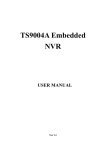
1
User Manual H.264 Standalone DVR 16CH 1 For further help, please visit www.zmodo.com User Manual for Zmodo DVR Thank you for buying our DVR Dear customer, thank you for choosing to purchase and use our product! If while using this product you encounter any technical problems or problems with quality, please contact us. We are ready to serve you. Before using this product, please carefully review the warranty information. 1. Service Contract This device may be returned for a refund from the seller within 30 days. Outside the return policy and within 90 days of the purchase, a defective device will qualify for a replacement at the discretion of Zmodo. This device otherwise comes with a 1 year limited parts and labor warranty. 2. Requirements for Return or Replacement The products outward appearance should have no scratches, dirt, dents, blemishes, or alterations of any kind. A copy of the purchase invoice and warranty certificate will be required. 3. In the event of the following situations, regardless of expiration Date, location, repair or part replacement, our company must receive payment, and is not liable for any payment to the consumer. All resulting loses will be the consumer’s responsibility: In cases of use causing the product’s malfunction or damage, or if the environment is not suitable for the product’s usage and causes malfunction or damage; In cases of natural disasters, as defined by law, or unavoidable circumstances that are not related to the product’s quality that cause the product’s malfunction or damage; In cases that the consumer’s purchase receipt and the product ID number/model number written on the warranty card are inconsistent; In cases that the consumer’s use, care, or protection inadvertently cause the machine’s malfunction or damage; In cases that the product’s up-to-standard certificate is damaged; In cases that there is no purchase receipt or warranty card; In cases that the repair warranty has already expired. 4. No other warranties, other than Zmodo’s repair warranty rules are acknowledged. 5. In order to ensure consumer’s rights, please carefully read the repair warranty content. 1 User Manual for Zmodo DVR Contents Chapter 1 Product Introduction ............................................................................................................ 4 1.1 Brief Introduction .................................................................................................................................... 4 1.2 Main Features ......................................................................................................................................... 4 Chapter 2 Installation ............................................................................................................................. 6 2.1 Package Content .................................................................................................................................... 6 2.2 Front Panel Operation ........................................................................................................................... 6 2.3 Rear Panel Operation ............................................................................................................................ 7 2.4 Remote Control....................................................................................................................................... 8 2.5 Hard Disk Installation ............................................................................................................................. 9 2.5.1 Installation Procedure ................................................................................................................. 9 2.6 Real Panel Connection .......................................................................................................................... 9 Chapter 3 Menu Description ............................................................................................................... 11 3.1 Menu Structure .....................................................................................................................................11 3.2 Menu Operations ..................................................................................................................................12 Chapter 4 Operations ........................................................................................................................... 12 4.1 Power on DVR ......................................................................................................................................13 4.2 Preview ..................................................................................................................................................14 4.2.1 Channel Status Display Area...................................................................................................14 4.2.2 System Status Bar ....................................................................................................................16 4.2.3 Tool Bar .......................................................................................................................................16 4.3 Record....................................................................................................................................................17 4.3.1 Manual Record ..........................................................................................................................18 4.3.2 Record Schedule .......................................................................................................................18 4.4 Camera Control ....................................................................................................................................18 4.4.1 PTZ Control ................................................................................................................................19 4.4.2 Motion Detection Setting ..........................................................................................................20 4.4.3 Mask Setting ..............................................................................................................................20 2 User Manual for Zmodo DVR 4.5 Playback ................................................................................................................................................20 4.6 Backup ...................................................................................................................................................22 4.7 Alarm Settings .......................................................................................................................................22 4.7.1 Alarm Input .................................................................................................................................22 4.7.2 Alarm Linkage ............................................................................................................................22 4.7.3 Alarm Defense and Schedule ..................................................................................................23 4.7.4 Device Exception Action...........................................................................................................23 4.8 Network Operation ...............................................................................................................................23 4.8.1 Network Settings .......................................................................................................................23 4.8.2 Web Client Operation ...............................................................................................................25 4.9 Maintenance ..........................................................................................................................................30 4.9.1 Log View .....................................................................................................................................30 4.9.2 Upgrade ......................................................................................................................................30 4.9.3 Device Information ....................................................................................................................30 4.9.4 Format HDD ...............................................................................................................................30 4.9.5 Log Out .......................................................................................................................................31 4.9.6 Restore to Factory Defaults .....................................................................................................31 4.9.7 Input/output Parameters...........................................................................................................31 4.9.8 Auto-maintenance .....................................................................................................................31 4.10 Advanced Settings .............................................................................................................................32 4.10.1 Settings of System ..................................................................................................................32 4.10.2 User Management ..................................................................................................................32 4.10.3 Advanced Setting of Record..................................................................................................33 4.10.4 Advanced Settings of Video ..................................................................................................33 Chapter 5 Appendix.............................................................................................................................. 34 5.1 Product Specifications .........................................................................................................................34 5.2 Methods of Calculating HDD Capacity ..............................................................................................36 5.3 Default Values .......................................................................................................................................37 5.4 Introduction of Mobile Phone Monitor ...............................................................................................39 3 User Manual for Zmodo DVR Chapter 1 Product Introduction 1.1Brief Introduction This series DVR is a H.264 main profile standalone DVR with Pentaplex functions: record, playback, live preview, remote preview and backup supported. It is a professional, high performance intelligent audio & video solution with a user-friendly GUI and practical industrial design. This series DVR is suitable for civil applications such as a home, office, and small business beside the common security and surveillance applications. 1.2 Main Features Compression 16-channel video input and H.264 compression standard with each channel being compressed independently in real-time CIF resolution. 4-channel audio input and G.726/ADPCM-IMA compression standard with each channel being compressed independently in 24Kbps. Compressed video & audio are synchronous. You can select either mixed stream or individual video stream. Four-level selection of record quality and self-defined bit rate and frame rate supported. Adjustable video parameters. Multi-area motion detection. OSD (On Screen Display) of channel name and time supported. Recording Manual record and schedule record supported. The schedule record types include: timed, motion detection, and alarm. SATA hard disk supported. Backup and clip record files through USB flash disk, portable USB HDD, and USBCD/DVDRW supported. Preview and Playback Simultaneous output of VGA and VOUT to TV. Up to 4 channels playback in fast play mode, slow play mode, rewind and single frame forward supported. OSD of channel name and time supported. Status displaying of local record, alarm and motion detection supported. Control Controlling of PTZ and dome supported. Controlling multiple DVRs with one RS485 keyboard. Setting and calling preset, sequence and track supported. 4 User Manual for Zmodo DVR Alarm Local alarm (includes exception and motion detection, video loss, and hard disk full) triggered handling supported. Alarm linkage: triggered record, linkage alarm output and linkage PTZ preset, sound alarm, report to alarm center, linkage channel single screen display and E-mail. Network TCP/IP, PPPoE, DHCP, DDNS supported. Real-time preview, downloading and playback remotely through network supported. Controlling of PTZ, configuring device parameters, acquiring device status and logs, and upgrade remotely through network supported. Local recording through network supported. 5 User Manual for Zmodo DVR Chapter 2 Installation This chapter provides a general description of the device’s interfaces and connections. It will describe how to install a hard disk drive, the buttons on the front panel, and the connections on the back panel. 2.1 Package Content After removing the DVR from its shipping box, unpack the contents on a flat surface or immediately place it where it will be located. Please refer to the “Package Contents” to ensure you have the entire contents. 2.2 Front Panel Operation Table 1-1 Front Panel Description Type Name Numbers:0-9 Input numbers. One key channel selection in preview mode. One key channel selection in play mode. Numbers:10+/0 Used in combination with 0-9 to select channels 10-16. PWR Green LED indicating DVR is powered on. HDD Green LED indicating that the hard disk drive is being accessed. May be solid or intermittent. Buttons LED IR Arrow Buttons: 【▲】 【▼】 【 】 【 】 Main Functions Description Green LED. Will blink to indicate the use of the remote control in conjunction with the DVR When in menu mode press【 】,【 】to move the selection boxes. press【▲】,【▼】to select submenu parameters. OK Press it to confirm operations in menu mode. Press it to select record type in setting schedule. Press it to change status of the current motion detection block. POWER Press it to power off device. REC Press it to start/stop manual recording. FN Press it to switch from single camera to multi camera view and back in preview and playback mode. Press it to enter/exit continuous selection when setting motion detection area and schedule record. 6 User Manual for Zmodo DVR Press it to set start time and end time in file search. ESC Return to upper menu. The same as 【ESC】button of remote control. PTZ One key PTZ control TV/VGA Switch the TV/VGA default output. REW<< Play in slow mode/fast rewind PAUSE 1.Play FWD>> Fast Forward STEP Go to next frame STOP Stop 2.Pause 2.3 Rear Panel Operation Table 1- 2 Rear Panel Description NO. Interface Description 1 Video In 16-channel video input: BNC(1Vp-p,75Ω) 2 TV Out 1 channel TV output: BNC(1Vp-p, 75Ω) 3 Audio Out 1 channel audio output: BNC(2Vp-p, 600Ω) 4 Audio In 4-channel audio input: RCA(2Vp-p, 600Ω) 5 VGA output 1 DIN-15 Network interface 1 RJ45 USB interface 2 USB 2.0 7 RS485 1 Half duplex(+ -) 8 Alarm in 4-channel switch-level input, N/O or N/C 9 Alarm out 1 channel switch-level alarm output 10 Power DC12V 6 7 10/100M self-adaptive User Manual for Zmodo DVR 2.4 Remote Control Table 1-3 Remote Control Description NO. Name Description 1 Rec Record 2 Power Press it to power off device. 3 Numbers Input numbers or select to switch among relevant channels. 4 Function Buttons DEL: Delete Arrow Buttons When in menu mode, press 【 】,【 】to move selection boxes. Press 【 ▲ 】 , 【 ▼ 】 to select submenu parameters. OK 1) Press it to confirm operations in menu mode. 2) Press it to select record type in setting schedule. 3) Press it to change status of the current motion detection block. 5 6 7 Switch from single camera and multi-camera viewing modes. 8 FN 1) Press it to switch from single split to multi split view mode, or reverse in preview and playback mode. 2) Press it to enter/exit continuous selection when setting motion detection area and schedule record. 3) Press it to set start time and end time in file search. 9 MENU Opens DVR main menu. 10 ESC Return to upper menu. 11 PTZ One key PTZ control 12 Backup Backup record 13 TV/VGA Switches the default output between TV and VGA. 14 CLEAR Alarm off. 15 SEQ Call sequence : Stop 16 : 1) Play/Pause 2) One key file search. Play Control Buttons : Play in slow mode/fast rewind : Go to previous section 8 User Manual for Zmodo DVR 2.5 Hard Disk Installation The hard disk is not included in factory configurations. Users can mount a suitable hard disk by calculating its capacity referring to “Appendix5.2 Methods of Calculating HDD Capacity”. 2.5.1 Installation Procedure 1. 2. 3. 4. 5. Open the DVR case. Take out the screw package, and mount the screw into the clamping slots in the case. Connect the HDD data cable and HDD power cable to HDD. Attach the hard disk by aligning installation holes to the case, hold and fix them by 4 M3*12 Head Screws plus plain washers. Connect the HDD data cable and HDD power cable to the correct interfaces on the mainboard. Replace the DVR top cover, and attach it with the included screws. Note1: Please use a HDD that is rated for security camera systems and purchase from a reputable retailer to ensure quality. See http://kb.zmodo.com/article.php?id=176 for assistance choosing a hard drive. Note2: Please format HDD after installation, or the system will show an error notification of “Hard disk error” accompanied by an audible alarm. Please see 4.9 Maintenance for details. 2.6 Real Panel Connection *Power Input Connect power adapter to Power Input interface of DVR. Confirm that the DVR power supply input switch is positioned correctly for the local voltage before connecting and powering on the unit. Turn on the unit by flipping the switch on the power supply. The power LED will light if the power cable is connected correctly. Note: Please use the power adapter contained in the package (Output will read 12v/5a). *Video Input The video input interface is a standard BNC socket, 1Vp-p, 75Ω. Note: The video signal cable should be kept away from any interference such as electromagnetism. *Audio Input The audio input interface is standard RCA socket, 2Vp-p, 600Ω. Note: The audio input resistance is a little bit high; please use active sound collection device or active microphone. The audio signal cable should be kept away from any interference such as electromagnetism. 9 User Manual for Zmodo DVR *Network Input The network input interface is RJ45 10/100M self-adaptive. Note: Confirm that the network band width is enough for transmitting high definition image smoothly. A 4 or 8 channel DVR will require 512kbps upload and a 16 channel DVR will require 1mbps upload speed from your ISP. *Alarm Input and Output The alarm input device should be the type of GND connected alarm or voltage input alarm, which can be set as N/O. or N/C. The requirements for the signal input level for voltage input alarm type is: low level: 0~2V; high level: 5~15V. The green angle pins of the signal cable are supplied for access of PTZ and alarm devices. Please follow these steps to connect: 1. Pull out the angle pins that inserted in the alarm input and output interfaces. 2. Screw out the screws by micro Philips screw driver, insert the signal cable into interface under spring, and then tighten the screws. 3. Plugin the connected pins into green angle pin socket. *PTZ Input Connect the PTZ control interface to RS485 interface on rear panel. The connection method is similar as above. Note: Please refer to PTZ manual for setting specific parameters, for some PTZ devices contain multiple telecommunication protocols, baud rates and IDs. *Video Output Interface: TV (BNC) and VGA. Note: VGA and TV cannot be selected in the operation interface simultaneously, but may be switched by the mouse, front panel, or remote control in the menu. 10 User Manual for Zmodo DVR Chapter 3 Menu Description 3.1 Menu Structure 11 User Manual for Zmodo DVR 3.2 Menu Operations Press [SET] button to enter into system setting screen. Press [●] button to start/stop recording manually. Press [►] button to play record file. Press [PTZ] button to enter into PTZ control screen. Note: This manual shows the Menu selection icons and selection boxes in【XX】; the buttons in the menu screen (except menu selection icons) in <XX>; the buttons on front panel and remote controller in【XX】. The highlighted menu is the active menu. Users can change the highlighted icon to the menu needed using【▲】,【▼】,【◄】,【►】button, and pressing【OK】button to confirm selection, or pressing 【ESC】button to return to previous menu. Selection box: Users can change the highlighted icon to the selection box needed using the 【◄】, 【►】 buttons, and press the【OK】button to confirm selection. Multiple items are allowed to be selected together at once by left clicking on the mouse. Sub menu list: Users can change the highlighted icon to the sub menu needed using【◄】, 【►】 buttons, or by using the scroll wheel on the mouse to select directly. Only one item can be selected here. Edition box: When in edition box, user can type in numbers directly by pressing number buttons. Press 【DEL】 to delete the character before cursor and press 【OK】 or 【ESC】 button to exit. Sub screen button: Press it to pop up sub screen. When in sub screen, select 【Confirm】 to save configuration and return to the upper menu. Press 【ESC】 or select 【Cancel】 to return to the upper menu without being saved. Use 【◄】,【►】 to move highlight icon to any of the selection boxes. Press 【OK】 button to switch to another selection status. Use【▲】,【▼】 to specify the sub menu value, where a sub menu selection exists. Exit: User can click 【 】 button on the right upper corner, or single right click mouse, or press 【ESC】 button to enter into the Save & Exit screen. From here you may choose to save your changes and then exit or just exit. 12 User Manual for Zmodo DVR Chapter 4 Operations 4.1 Power on DVR *Start-up The Power LED will light after powering on correctly. Please refer to “2.6 Rear Panel Connection” for details of the connection method. Press【Power on/off】 button to start up device. The preview screen will appear. After pressing the【ESC】 button on the front panel or remote, or right clicking mouse, the login box appears. Here you will select your user ID and enter the appropriate password. Note1: Start up may take anywhere from 1-2 minutes. Please be patient. Note2: You may modify passwords by selecting <Tool Bar>→<System>→<Password Setting>. Enter the current password, then you may enter your new password, confirm it, and click OK. The new password will take effect immediately. Note3: Default password for Admin is 111111. Default password for User is 111111. Admin password can be restored to factory defaults by short-circuit “JP 1” on the motherboard. After logging in to the DVR as Admin, the Admin user can change other user’s passwords. The system supports 8 users, and the Admin is the account manager with all permissions, whose name cannot be deleted or changed. The Admin user can add and delete all other users and permissions with those corresponding users. Note4: The DVR can identify display devices automatically. When connected either to VGA or TV, the menu will be on the specified screen automatically after start-up; when connecting VGA and TV simultaneously, two images will be displayed on the screen, but the menu system will display only on the currently selected video output. The user may switch the output by clicking icon in the tool bar. *System settings Language: Please enter <Tool Bar>→<System>→<System Setting>→<Language> to set language. VGA Resolution: Please enter <Tool Bar>→<System>→<System Setting>→<VGA Setting> to set VGA resolution and refresh rate. It supports 800×600@60Hz, 1024×768@60Hz, 1280×1024@60Hz, 1440×900@60Hz currently. WARNING: Setting an inappropriate resolution will give you a blank screen. Date/Time: Please enter <Tool Bar>→<System>→<System Setting>→<Time Format> to set time format. 12 and 24 hour clocks are supported. Please enter<Tool Bar>→<System>→<System Setting>→<Time Setting> to set the date and time. Video Standard: Please enter <Tool Bar>→<System>→<System Setting>→<Video Standard> to set video standard. PAL, SECAME, and NTSC are supported. Please set according to camera’s parameters. 13 User Manual for Zmodo DVR Note1: In order to avoid record files’ time confusion, you’d better stop recording before modifying system time. Note2: “Language” and “Time” will take effect instantly. “Record Resolution” and “Video Standard” will take effect after being saved. Note3: When the resolution setting exceeds the range of the display, please click 【ESC】->【2】-> 【ESC】on the Front Panel or remote control (within 3 seconds) to reduce the resolution to 800X600 @60HZ. Note4: All Zmodo cameras are NTSC cameras. If your image is in black and white and rolling, please check this setting to verify it is not on PAL or SECAME. 4.2 Preview After starting up the system, the screen has a live view area and a tool bar. Right click on the mouse in preview mode or press【OK】on the front panel to make the System Status/Tool Bar appear. System status bar can be dragged to anywhere on the screen by the mouse. It will go back to the original position after a device reboot. The system status bar will switch to the Tool Bar by right-clicking on the mouse and hidden by right clicking again. The camera images, channel name, record time, and alarm notifications will be displayed on the main screen. 4.2.1 Channel Status Display Area Under preview mode, channel shows current input image and channel status information (video status, mode, and motion detection). *View Mode Switching When in 1/4/6/8/9/16 split view mode, the tile with a light green border is the current selected channel. User can use the mouse or press 【Direction】 buttons to switch to another tile. If the audio output device is connected, the audio can also be heard together with the video when the matching channel is selected. The audio will also be heard on its corresponding channel in playback mode. User can select to display a single particular channel by pressing the Numbers buttons. When in preview mode, user can enter into 1/4/6/8/9/16 split view mode by pressing 【FN】 button directly, or by the toolbar. 14 User Manual for Zmodo DVR *Image Parameters Setting Please enter <Tool Bar>→<System>→<Video>→<Color Setting> to set brightness, contrast, hue and saturation. It will take effect instantly. Note1: User can set image parameters of one channel one at a time or all channels at once by selecting 【All】 in <Camera Channel>. Note2: In preview mode, brightness, contrast can be adjusted by remote controller directly. *OSD Settings The OSD of channel name and system time is supported. Please enter <Tool Bar>→<System> →<Record Setting>→<OSD Setting> to set. The channel name will be displayed on upper left corner and the channel time will be displayed on the upper right corner of the camera window. *Channel Status Display Area The channel statuses include: “motion detection triggered recording” / “common recording” / “motion recording”/ “alarm triggered recording” / “external alarm input” /“alarm output”. Indication of “motion detection” / “common recording” / “alarm recording” will be displayed on the right upper corner of screen. The details are as follows: Indicates “motion detected”. The settings of motion detection include sensitivity and area selection. Please see “Motion Detection Settings” for details. Blue indicates “common recording”. Please see Record for details. Green indicates “motion detection triggered recording”. Red indicates “alarm triggered recording”. Grey indicates “manual recording”. Indication of “external alarm input” / “alarm output” will be displayed on system status bar or Tool Bar. The details are as follows: : The 4/8 icons indicate the alarm input status. If alarm record mode is set, the icon is otherwise it is . When triggered, it changes into red , External alarm input can trigger multiple events handling rules. Please see Alarm Settings section for details. : This icon indicates an alarm output. When the alarm output is in effect it will display this symbol. 15 , User Manual for Zmodo DVR 4.2.2 System Status Bar In preview mode, the system status bar will display current system status, including: "External alarm input" "Alarm output" / "hard disk capacity" / "number of the client connection" / "system time." Indicates hard disk being OK. The number indicates the percentage of the total capacity of the hard disk. Indicates “Hard disk error” or “No hard disk”. Indicates client connection. The number shows client linking number. Indicates “No client connection”. 4.2.3 Tool Bar Right click mouse or press [OK] button in preview mode, the Tool Bar shown as below will appear. 16 Channel DVR’s tool bar is as follows: : Hide the tool bar. : System configuration. Please see “3.1MenuStructure” for details. : Manual record. Please see “4.3.1 Manual Record” for details. : Search, playback and backup record files, please see “4.5 Video Playback” and “4.6 Video Backup” for details. : PTZ operation. Please see “4.4.1 PTZ Control” for details.. : Click to cancel alarm notification. Click this button will pop a message to show the present alarm information. : Fast play back. User can enter 10, 20, 30, or 60 seconds before position to start playback and can also jump to a specified time in the video. : Shut down. Click this button will pop a message of “confirm password”. User has to enter Admin password to shut down. , , , , , : To set the preview mode of “Single splits view” , “4 splits view”, “6 splits view”, “8 splits view”, “9 splits view” ,“16 splits view”. : Switch between TV and VGA. Menu will not be available on the current screen, only a preview image. : Adjusts the screens overall display location on the display, 8 pixels per unit. 16 User Manual for Zmodo DVR , : To reduce or increase screen in vertical direction. , : To reduce or increase screen in horizontal direction. , , , : To move the screen up, down, left, right. : To zoom out the screen to largest and show in central. Note1:When the mouse hovers over a toolbar icon, it will display that buttons menu function in a floating text box next to the cursor. Note2:When video source is PAL, screen display range max is 720*576;When NTSC, screen display max 720*480. Note3: You may switch the display menu between VGA and TV by selecting 【ESC】->【1】->【ESC】 (sequence must be pressed within 3 seconds) on the remote control or Front panel. 4.3 Record Record type contains manual record and schedule record. The priority of manual record is higher than schedule. If the record schedule is conflicting with manual record, the manual record will be processed first, until the manual record is disabled. Record types include “common recording” / “alarm triggered recording” / “motion detection triggered recording” / “alarm motion detection triggered recording”. Each of them is indicated with a grid of different color, and each color indicates a particular record status. Please see ”4.3.2 Record Schedule” for details. Record resolution: The device support "CIF" format. Record quality: “Best 768Kbps” / “High 640Kbps” / “Better 512Kbps” / “Common 384Kbps”. And “User setting” can help user to set one channels bit rate up to 2048Kbps. Record frame rate: if the current selection is PAL, the frame rate options are “Full” / “12” / “6” / “3” / “1” / “User-defined”. If the current selection is NTSC, the frame rate options are “Full”/ “15” / “7” / “3” / “1”/ “User-defined”. Default is “All”, 25 fps for PAL and 30 fps for NTSC. Record Resource: “Video” for video only or “Video and Audio” for recording video and audio. 17 User Manual for Zmodo DVR 4.3.1 Manual Record Please enter <Tool Bar>→<Manual Record> to enable or disable manual record on specific channels. Press the 【●】 button to start/stop recording manually. Note1: The video type shown in the playback menu for “Manual Record” will appear as “Common Record” Note2: When Manual Record is enabled, it takes precedence over any Record Schedule settings. 4.3.2 Record Schedule Please enter<Tool Bar>→<System>→<Record Setting> to set record schedule. The setting screen is shown as the figure below: Area 1: The current recording channel number. Area 2: The record schedule. Area 3: Description of record type. The grid based recording schedule allows users to customize a schedule by inputting different record types for days of the week on horizontal columns and hours of the day on vertical columns as matches the users’ needs. ① Move highlight icon to a time grid using 【Direction】 buttons. ② Specify the recording type by repeat pressing 【OK】button or double left clicking mouse,(the color of the grid will change relevantly). Alternatively with the mouse you may click on a record type selection at the bottom and then click and drag across the grid to change large grid portions at once. ③ Select 【OK】 to confirm settings. The settings will take effect after being saved. Note1: User can copy the current Record type onto the neighboring grid by pressing 【FN】 button first , 【Direction】 buttons secondly, and then the【FN】 button again to exit. Note2: When motion detection recording is selected, the motion detection sensitivity and area should be set to match your needs. Please refer to “4.4.2 Motion Detection Settings” for details. When alarm recording is selected, the alarm triggering settings should be set to match your needs. Please refer to “4.7.2 Event Handling” for details. 18 User Manual for Zmodo DVR 4.4 Camera Control 4.4.1 PTZ Control *PTZ Settings Enter <Tool Bar>→<System>→<Video> to set camera channel, protocol, baud rate and ID. Note: The different PTZ controlled by one PCI should have the corresponding PTZ ID. There are 256PTZ ID supported currently: 0-255. *PTZ Operations In preview mode, select a camera first (in 4/9/16 splits view mode, the selected tile is has a green highlighted border) using mouse or 【Numbers】buttons, and then enter <Tool Bar>→<PTZ Control> to bring up the PTZ control menu as shown below: NO. Name Description ① Direction Click the arrow icons to control the pan and tilt of PTZ. Click the center icon to call sequence or run scanning. Please refer to the PTZ manual for details of PTZ scanning mode. ② Speed Set the turning speed of PTZ camera. ③ Advanced Click ④ Focus Click to focus-in and focus-out (it is disabled for cameras with an automatic focus). ⑤ Iris Click to make the image brighter or darker (it is disabled for cameras with automatic iris adjustment). ⑥ Auxiliary Open/close auxiliaries. Click to open and click to close. Different functions respond to different protocols. The auxiliaries include light, rain brash, power, etc. Please refer to PTZ Cameras manual for details. NOTE: Up to 2 auxiliaries are supported on DVR side. Up to 4 auxiliaries are supported on the Web Client. ⑦ Zoom Click to zoom in/zoom out. Preset 1. Select the preset number in the preset window. 2. Position the camera as desired position. Save the position by clicking step 1 and 2 to reset the desired position. ⑧ and to show/hide the advanced setting options. 19 . Repeat the User Manual for Zmodo DVR 3. Call preset: Select the preset number you want to call, and click on the go to button . 4. Clear/reset preset: Select the preset number you want to clear/reset and click on the clear button . ⑨ ⑩ Sequence Sequence is a running route of the camera that passes through multiple presets. Set sequence: 】 1. Select preset number you want to call. Click on set button . 2. Repeat step 1 and 2 to add the other presets till finishing. 3. Click button to end setting. Click on button to clear sequence. Track Track is a continuous running route of camera. Set track: Click on to start setting. Move camera as the track and pattern you want it to run. Click on again to finish setting. Click on to run track and click again to stop running. Note: Whether Track is supported or not depends on the type of PTZ. 4.4.2 Motion Detection Setting Motion detection settings include sensitivity and area. The sensitivity includes three levels: High, Med, and Low. Please select <Tool Bar>→<System>→<Video>→<Motion Detection> to set schedule and area settings. With the grid displayed for both schedule and area detection settings click and drag mouse to alter the schedule and area settings. Areas not covered by a blue box on area detection grid will be disabled for motion detection. Front Panel Operation: The area detection grid is displayed as 16 X 12 blocks on screen. Move highlight icon among the blocks by using [◄], [►]buttons. Please follow these steps below to set: 1. Move highlight icon to one of the blocks you want to adjust by using [◄], [►] buttons. Press [OK] button to adjust that blocks setting. An active motion detection block will be colored blue. 2. Press [FN] button to open a multi-box selection grid. User the [Direction] buttons to expand grid in desired directions. Once the grid covers the desired area, press [OK] to adjust the entire grids setting. 3. Repeat steps 1 and 2 until finished. 4. Press [ESC] to exit grid. In the Motion Detection Schedule Settings, users are free to schedule motion detection capabilities being on or off based on a grid which allows for hourly and daily customization throughout the week. 4.4.3 Mask Setting The mask setting function can make some regions of the camera image invisible. These regions in both live preview and playback will be masked out in black. The method to set the mask is similar to the motion detection setting. You may click and drag to select an area to mask out. Right clicking on a masked area will remove the mask and right clicking in a non-masked area will exit the masking screen. A total of 4 masking blocks can be added to each channel. 20 User Manual for Zmodo DVR 4.5 Playback * File Search Select <Tool Bar>→<Record Search>. Specify the date/time and channel number. Click 【Search】 in the pop-up screen to start searching. The search results will be listed on the screen in corresponding colors so as to distinguish different recording types. Please see Fig IV-2Record Schedule for details of colors description. You may click the mouse or use panel to specify time. Panel operation: Move highlight icon to relevant selection box using [◄],[►] buttons. Move highlight icon to date/time selection box, modify time using [▲],[▼] buttons. Move highlight icon to channel selection box, press [OK] button to select it or cancel selection. Move highlight icon to , press [OK] button to zoom in/zoom out the timeline (time ruler). If the desired time is not shown, please move highlight icon to and press [OK] button to move the timeline to the desired time of day. After setting time, channel number and timeline, move highlight icon to [Search] using [◄],[►] buttons, and press [OK] button to display the recorded files on the timeline. Once the video files are displayed, press [FN] button to enter the timeline and bring up your start point selection. Press [◄],[►] buttons to move your start point. Press [FN] to confirm selection. Press [FN] again to bring up the stop point, Press [◄], [►] buttons to move the stop point to desired location and press [FN] to confirm selection. After a start and stop point for viewing are selected, move highlight icon to [Play] using [◄],[►] buttons and press [OK] button to start playing. Move the highlight icon to [Backup] using [◄],[►] buttons, and press [OK] button to bring up and begin file backup of the selected time frame. * Playback Control : This will allow for rewind in playback. Available speeds are 8X and16X. : Allows you to pause or resume playing current playback video. : Stop playback video. : Allows fast forwarding through playback video. Availablespeedsare1X, 2X, 4X, 8x 16x, 1/2X and 1/4X. 21 User Manual for Zmodo DVR : Go to the next frame. : Click to switch from single view mode to 4/9 split view mode, or back. 4.6 Backup Enter<Tool Bar>→<Playback> to search, backup or playback the desired video files. Click 【Backup】 to enter into the backup screen. The DVR will auto-detect all compatible devices available (such as a flash drive) and display them. Select the appropriate device and the preferred video format first, and then click 【Backup】 to start transferring video to the selected device. Note: The video format types include AVI and MP4. For AVI type, device will automatically back up the video to USB device. Please install the player which supports AVI format to view the video. 4.7 Alarm Settings Please make sure that the alarm input and output cables are connected correctly. Please refer to Rear Panel Connection for details. Select <Tool Bar>→<System>→<Alarm> to configure alarm parameters. Note: All the settings will take effect after being saved. 4.7.1 Alarm Input The alarm input attribution includes N.O. and N.C. Please select a suitable attribution according to the types of alarm devices connected and methods of operation on the alarm device. N.O.: Normally open. Alarm is triggered when the circuit is completed. N.C.: Normally connected. Alarm is triggered when the circuit is disrupted. 4.7.2 Alarm Linkage The alarm triggered event handling includes: record/PTZ preset/alarm zoom out/buzzer/upload/ E-mail /upload via FTP. The channel alarm input can zoom the display in intervals of 1-10s (optional). If the display interval time is set to off, the zoom display will be disabled. After using the “zoom out image”, Alarm zooms out and IE client preview will zoom out simultaneously. Note1: If user wants to set alarm triggered record, please set the record schedule first at “Record Schedule”. Note2: If user wants to set alarm triggered PTZ, please select the channel number first, and then to set (only preset 1 can be selected). Note3: After alarm, email will be sent immediately with the attachment of the caught snapshot. 22 User Manual for Zmodo DVR 4.7.3 Alarm Defense and Schedule User can enable a customized alarm schedule in the advanced menu, which is similar to setting the recording schedule. In the alarm defense status, the icon of alarm input will appear as yellow. 4.7.4 Device Exception Action Select < DEVICE EXCEPTION ACTION > to enter the “Device Exception Action” screen. Choose among these three options: HDD full, Off line, and IP collision. For the hard drive setting the user can select “alarm output”/ “buzzer”/ “upload”/ “email”. Off line and IP collision can only be set to “alarm output”/ “buzzer”. After these settings have been saved, device exceptions will be handled the way as user has selected. 4.8 Network Operation 4.8.1 Network Settings Please enter<Tool Bar>→<System>→<Network Setting>→<Network>. There are three connection types available: Static IP, DHCP and PPPoE. *Static IP: If this type selected, please type in an IP address, subnet mask, and gateway. User can ping the IP address to check its connection status from a computer. *DHCP: If this type is selected, the DVR will attempt to automatically pull an IP address, subnet mask, and gateway from the network it is connected to. A result of all 0’s indicated either a bad connection or no connection. Note: It will not populate the information until DHCP has been saved and you have re-entered the menu. *PPPoE: Click 【】, the PPPoE setup screen will appear. Type in user name and password and click 【OK】 to confirm. System will dial automatically. After accomplishing dialing, the IP address will be assigned and displayed automatically in the IP Address line. You can save the user name and password even if the dialing is not successful. Note: PPPoE addressing is very rarely used. Please consult your Internet Service Provider if you believe you should be using this setting. - More Network settings *HTTP Port: It is the port number used for browsing through Internet Explorer. The default is 80. *Command Port: It is the first entry port for communication between the web client and the device, which is mainly used for controlling log-in, log-out, real-time preview, remote playback, and remote download, etc. *Media Port: It is for media stream transmitting including real-time stream, voice stream and file stream etc. 23 User Manual for Zmodo DVR *DDNS: Click 【】, the DDNS setup screen will appear. Select a DDNS server and type in the DDNS address, user name and password. You can set these up with the company that runs the selected utility. *Auto Register: Select activating Auto Register and click【】, the register setup screen will appear. Type in the registration server IP, port and register interval time. *File sharing: Please refer to http://kb.zmodo.com for more information about it. *Email Setting: Click 【】, the EMAIL setup screen will appear. To take effect this function, must be paired with an alarm email setting. Enter the SMTP mail server address in the screen, the corresponding SMPT port number (if the port uses SSL, you must check the box indicating such as the desired email address to be used for sending the email, that emails corresponding password, please check the validating identity box), and the recipient email address. Press the [Test] button, the mail address will send a test email if the settings match up to the chosen email address. *Mobile port: This port controls all information transmitted for viewing and control via a mobile device such as a smart phone or tablet when used in conjunction with the Zviewer application on the device. *FTP server: Please refer to the previous section regarding file sharing. *UPnP: To start UPnP set the feature to on and select []. UPnP, short for universal plug and play, when connected to a network with the same feature will automatically map out and open the necessary ports in order of the user to be able to view the system through the internet. Not all networks or routers in use today have this feature. Refer to your routers user manual for more information on compatibility. *IP ACCESS: When disabled any PC (IP address) can access the device. When set to “Allow Access” only devices using IP addresses entered into, this setting will be allowed access to the IE web client and all others will be restricted at the log in screen. When using the “Forbidden” setting, any device will have access to the IE web client with the exception of devices using IP addresses entered in to this category. Only one of these 3 settings is in effect at any time. *Time synchronization: Click [] to start synchronization. The device can automatically update its time and date based on the server information entered in this option. If turned off the device when connected to the internet will pull a date and time from a default server and update accordingly. Note1: Any settings adjusted in the network will not take effect until saved from the save menu. Note2: Currently mail using PPPoE is only supported if using the SMTP protocol. Note3: Please refer to our knowledgebase at http://kb.zmodo.com for this information. 24 User Manual for Zmodo DVR 4.8.2 Web Client Operation BEFORE PROCEEDING: Set IE ActiveX Controls. Instructions at: http://kb.zmodo.com/article.php?id=96 Open IE browser, type in the IP address of the DVR and the corresponding web port if you are using anything other than 80. The log-in screen will appear. Note1: If PPPoE or DHCP is selected, the user should check the IP address again after restarting device. Note2: If it is the first time logging in through IE, after setting ActiveX as mentioned above you will have to install the IE Add-On associated with the DVR. The default user name and password are: Admin (case sensitive) and the password is either 111111 or 888888. Note3: Compared with the local side, the added settings on IE Web client side are as the table below: Settings added on IE side Menu Contents <Server>Tab Name of server is configurable on Web client side. <Channel>Tab The channel OSD is User-defined. <Device>Tab User can adjust Mini NVR time accordance with PC time. <State>Tab Device states can be viewed directly. 4.8.2.1 Web Screen Description *Address Display the DVR IP address. 25 User Manual for Zmodo DVR *Tool Bar The description of icons from left to right is: Configure device parameters. Search and playback record files. View logs and export them. Set the storage directory of record files. Click to switch image view modes among full-screen, single view and 4/8/9 split view mode. Log-out, restart device, Clear alarm *Alarm Notification When network connection is broken or abnormal, the alarm notification of “No heartbeat of device, please check the network!” will be displayed in the right up side of the main screen. After recovery of network, the camera preview will be displayed automatically. When alarms on remote notification occur, the alarm notification with alarm input number contained such as “Device alarm: IO alarm, IO input x” will be displayed in the right upper side of the main screen. When alarms of motion detection with remote notification occur, the alarm notification with the alarm channel number contained such as “Device alarm: motion detection, channel 1” will be displayed in the upper right side of the main screen. When alarms of video loss occur, the alarm notification with the alarm channel number contained such as “Device alarm: video loss, channel x” will be displayed in the upper right side of the main screen. *Preview , : Adjust image contrast up/down. , : Adjust brightness up/down. : Start/stop voice monitoring. The icon will turn to green when sound is on. : Start/stop recording. The icon will turn to green when recording. : Click to snapshot the image in the camera at that moment. : Stop preview. Note: Click to set the storage directory of record files and pictures captured. *PTZ Setting The PTZ setting of client web is similar as the PTZ operation of local device, please refer to “PTZ Control”. Note: IE side supports 3 auxiliaries setting. 26 User Manual for Zmodo DVR 4.8.2.2 Device Parameters Settings Click , the parameters configuration screen will appear. All of the configurations are divided into the following six selections: *Server This includes the configuration of server, network, and version information. All of these configurations can be set in [Tool Bar]→[System]. Note: If the DHCP mode selected, the IP address is assigned automatically without being modified. *Channel User can set motion detection, video loss, OSD, image bit rate and frame rate, image parameters and record schedule here. Note: User is allowed to set a single channel first, and then to copy the settings to the other channels. *Serial User can set PTZ protocol, baud rate, and address code here. All of these settings can also be done by selecting on the DVR [Tool Bar]→[System]→[Video]. *Alarm User can set IO alarm and event handling here. All of these settings can be done by selecting on the DVR [Tool Bar]→[System]→[Alarm]. *User Management Includes user authority and password settings. This will be found on the DVR at <Tool Bar>→<System>→<System Setting>→<Advanced Setting>, “User” authority and password can only be changed by “Admin” account. *Device Upgrade: Click [Browse] to select the software package needed, and click [Start Upgrade] to progress. User can stop the progress of upgrade by clicking [Stop Upgrade]. Adjust Time: Click [Adjust Time] to adjust time of device accordance with the PC time. WARNING: Changing times on the DVR will make previously recorded files unsearchable *State The information of HDD and channel state is contained here. 27 User Manual for Zmodo DVR 4.8.2.3 Playback Click , the playback screen will appear. It includes file search, playback and download. Note: In windows Vista or newer, when opening IE you must right click and choose “Run as Administrator” in order to use the playback feature in the IE Web Client. *File Search The file search part is on the right upper side of the screen, please set target, type, start time and end time there. Then click [Query] to start searching. The result will list on the table. Specify the files in the table list and click on the play control button or download button to do the indicated operations. *File Playback The play control screen is on the left side of the screen. It includes image display area, play control bar, and channel information. Click [Play], the recorded files selected will be displayed in chronological order. The progress of playing is shown as the figure below: The playing control bar is shown as the figure below. The descriptions of all these icons from left to right are as follows: : Play : Pause : Stop : Go to next frame : Fast Forward (The speed of playing will be doubled by each clicking. It includes:2X, 4X, 8X, and 16X). 28 User Manual for Zmodo DVR : Slow motion (The speed of playing will be half down by each clicking. It includes 1/2X, 1/4X, 1/8X, and 1/16X). : Enhance contrast. : Reduce contrast : Enhance brightness : Reduce brightness : Open/close voice : Go to previous file : Go to next file Note: ( and is enabled only when multiple record files being selected to play). : Snapshot (the storage directory can be set on the pop-up screen by clicking ). The information of the record file selected will be displayed in the area shown as the figure below. It includes device’s IP address, current play speed, channel number and start/end time of the record file. *File Download The File download operation part is on the bottom right of the screen. Click to set the storage directory of the file to be downloaded. Click [Download] to start downloading. 4.8.2.4 Bidirectional Talk Click in the Tool Bar to enable the bidirectional talk between IE Web Client and DVR side. A microphone should be connected to the computer through the Line-in interface and speakers and an audio capable camera or microphone are required at the DVR location. Click 29 again to stop talking. User Manual for Zmodo DVR 4.8.2.5 Log Click , the screen of device logs will appear. There are four options for choosing: All, according to time, according to type, according to time and type. To search logs, please select the search mode and channel number needed first and then click [Search] to progress. Click [Export] to export logs in html format. 4.8.2.6 Remote Upgrade Select <Server>-<Manage>, click [Browse] to specify the file for upgrade, and click [Start] to upgrade. User can click [Stop] to stop upgrading in progress. 4.9 Maintenance Select <Tool Bar>→<Settings>→<Maintenance> to enter maintenance setup. 4.9.1 Log View 1 Select the type of log to be searched: All/ Operation/ Exception/ Alarm/Front-end device. 2 Select the time scope to be searched. 3 Click [Search] to display the detail information of log. Note1: If the logs searched contains an alarm event log you can directly play the video recorded during the alarm event by clicking【►】on the right side of screen. Note2: The maximum number of logs supported currently is 10000. The system will automatically overwrite the oldest logs with the list becomes full. 4.9.2 Upgrade The upgrade modes supported now are USB and IE Web Client: USB: Please be sure the USB device is connected correctly and that the firmware upgrade has already been properly copied in to the drive. After accomplishing upgrade the Restart prompt screen will appear. Please restart the device, the latest software will be installed automatically then. IE: Please refer to “5.2.2 Device Parameters Settings” for details. 4.9.3 Device Information HDD Size: display the current total capacity of HDD and the remaining capacity. Hardware Version: display the hardware version on the DVR. Software version: display the current software version on the DVR. 30 User Manual for Zmodo DVR 4.9.4 Format HDD Please make sure that any important video files have already been saved prior to formatting HDD. Please stop all of the recordings before the beginning of formatting HDD. This will erase all video files on the DVR. 4.9.5 Log Out Please enter<Tool Bar>→<Settings>→<Save>→<Log Out>, the preview screen will appear together with the log-in box. Please type in your password for further operation. 4.9.6 Restore to Factory Defaults Please enter <Tool Bar>→<Settings>→<Save>→<Restore Defaults>. The DVR will prompt you on whether you would like to continue with removing all personalized settings. Click 【Confirm】to proceed restoring. Note1: Please refer to Appendix VI for the default values. Note2: The system language, time, camera P/N system, and network settings (IP address, subnet mask, gateway, and HTTP port ) will not be recovered by restoring to factory defaults. 4.9.7 Input/output Parameters Please enter <tool bar>-<system>-<maintenance>, when USB is connected, the device setting parameters can be exported to the USB device. Parameters can import to the device from USB to restore settings after a reset to defaults. Reboot the device, and the imported parameters will take effect. Note: Parameters may only be imported to the same model and software device as was saved from. 4.9.8 Auto-maintenance Please enter <tool bar>-<system>-<maintenance>. Auto-Maintenance allows for the DVR to reboot itself periodically (This is recommended). There are three types of maintenance: per day, per week, per time. Turn this feature off to prevent the DVR from rebooting. 31 User Manual for Zmodo DVR 4.10 Advanced Settings Note: Operations in this chapter require the operator to be logged in with Admin authority. 4.10.1 Settings of System Please enter<Tool Bar>→< Settings >→<System>→【Advanced Setting】. Preview Cruise: Select <PREVIEW CRUISE>→【】 to enter the setting screen. This feature will allow the DVRs display to cycle through the cameras 1 at a time or by groups instead of showing all at once. Set the preview cruise interval, 1/4/9 cruise way. It will take effect after saving the settings, the screen will be cruised in accordance with the setting intervals over the segmentation preview. To turn off Preview Cruise go in and select disabled and it will return to standard operation after saving. DVR ID: Setting this ID in accordance with a DVR Controller allows for operation of the DVR through the device. Please refer to the controller’s manual for operating instructions. Daylight Savings Time: Select <DST>-【】to enter DST settings. User can set beginning and ending dates and time of DST. Device will automatically adjust the time after being saved. Menu Overtime: After started <menu overtime>, when there is no mouse motion on the menu, will time out and automatically close the menu and lock the device. User will have to log in to the DVR with ID and password each time this happens. Channel Lock: Select <channel lock>-【】to enter channel lock setting screen. Select the desired channels to lock out and press 【OK】. The User will be unable to see any locked channels when the DVR is logged out. This setting can only be adjusted under Admin authority. 4.10.2 User Management *Add User: Please enter <tool bar>-<setting>-<system>. Select <ADD USER>→【】to enter the setting screen, the password of any new user is 111111. *Password Change: User may enter < Tool Bar>→< Setting >→<System>→<Password Settings> to modify the password. *Delete User: Select <DEL USER>→【】to enter the setting screen and delete a user. Only the Admin is capable of deleting a user. *Change Permissions: Select < AUTHORITY MANAGE >→【】to enter the setting screen. Authority setting contains the authority options of both local and remote access. 32 User Manual for Zmodo DVR Move highlight icon to desired option using 【Direction】 buttons. Press【OK】 button or click mouse to select the option. 4.10.3 Advanced Setting of Record Please enter <Tool Bar>→< Setting >→<Record>→【Advanced Setting>>】→<SUB STREAM>, select “On” and press【】 key to enter the setting screen. Then user can customize the sub-stream frame rate and bit rate. The Sub-stream supports a frame rate of 1-15, and a bit rate 32K-512K. 4.10.4 Advanced Settings of Video Please enter <Tool Bar>→< Setting >→<Video>→【Advanced Setting>>】. *MOTION HANDLING Motion Handling settings allow you to link specific actions to motion detection for the channel selected on the first page of the Video settings: “RECORD " / " ALARM OUT " / " BUZZER " / " UPLOAD " can all be linked or disabled when regarding motion on this page. Note: Please refer to “4.2.2 Motion Detection Settings” for the setting of detection area and sensitivity. *VIDEO EXCEPTION HANDLING After the selected video channel signal is lost, this setting will trigger the selected setting just as the motion handling page does for motion: " ALARM OUT " / " Buzzer " / " UPLOAD ". *CHANNEL NAME SETTING This feature will allow you to change the channel display name from “Channel 1”, “Channel 2”, etc. to any desired name. 33 User Manual for Zmodo DVR Chapter 5 Appendix 5.1Product Specifications Table5-1 Product Specifications DVR Type System I/O Interface Video Audio Environmental 16 channel DVR Linux 2.6 O/S Pentaplex operation: record, playback, preview, network browse, backup supported. Video Input BNC, 1Vp-p, 75Ω NTSC: 480 fps @ CIF / PAL: 400 fps @ CIF Audio Input RCA 4-channel Input VGA Output 800×600@60Hz, 1024×768@60Hz, 1280×1024@60Hz, 1440×900@60Hz Audio Output RCA 1-channel Output USB Interface Support USB storage device, USB mouse, USB burner. RS485 1 port, receiving and transmitting duplex supported. Network Interface RJ45 10/100M self-adaptive. SATA Interface 2 SATA port, 2 SATA HDD up to 2T supported. Video Compression H.264 Baseline Video Standards PAL/NTSC/SECAM Video Resolution CIF Frame Rate NTSC/PAL:480 fps/400 fps Video Output Bit Rate 32kbps-2048kbps (14M byte/hour - 922M byte/hour) Playback Resolution CIF Audio Compression G.726/ADPCM-IMA Input/output Sampling Rate 8KHz Audio Channel Type Mono Sampling Bit 16 bit Power Supply DC 12V, 5V Operating Temperature 0℃-+50℃ Operating Humidity 10%~90%RH Power Consumption <12W(without HDD) 34 User Manual for Zmodo DVR Table5-2 Main Functions Operating Interface Multiple control methods: mouse, IR remote controller, front panel and GUI with navigation supported. Recording status and alarming status can be displayed directly on desktop and front panel. Record Five recording modes: Manual, Schedule, Motion Detection, Alarm, and Motion Detection & Alarm supported. Selectable Record Quality: Best, High, Mid, Low and User-defined. Playback Play progress bar supported. Multiple channel video/audio playback simultaneously. Play, pause, stop, single frame forward, fast forward and backward (up to 4/9ruple when playback 4 channels) supported. Backup Multiple backup modes: USB flash disk. USB CD-RW, and DVD-RW supported. The output format can be H.264 RAW. Network IPv4, PPPOE client, DHCP client and TCP/UDP protocol supported. The Web Client and Client Application Software are provided for remote configuration, video browse, local recording, local and remote playback, and remote PTZ control. Network transmitting supports independent coding. The time delay of LAN is less than 300ms. Mobile phone monitoring Android and iOS devices are supported. Log Operation The log of operation and alarming will be saved automatically. User can directly play the record files that being record when the alarm event occurs. PTZ Control Multiple protocols: Pelco-P, Pelco-D, and Samsung, etc. supported. Upgrade of protocol supported. Multiple PTZ operations: Pan, Tilt, Zoom, Preset, Sequence, Track and Auxiliary Switch supported. Alarm Management 4 channel alarm input NO/NC supported. Motion detection and alarm of video loss supported. Trigger recording, Linkage PTZ preset and Bee alarm supported. The alarm information can be sent to Web Client or Client Application Software through network. Account Management Multi-account supported. Users can set & recover password, authentication management. Auxiliary Function Hardware Watch Dog supported. Device will be restarted if operation is non-responsive for 30 seconds or more . 35 User Manual for Zmodo DVR 5.2 Methods of Calculating HDD Capacity 1) Calculate the maximum capacity of the build-in hard disk. *Timing Recording: Step 1: Calculate the maximum capacity of the hard disk needed in selected channel per hour, suppose as Si (MByte) (i is the channel number), and suppose the bit rate of the channel selected as D (Kbit/s). The formula of calculation is: Si =(D*3600)/(8*1024)= D * 0.439453125 MB Step 2: Confirm the storage time length, suppose as T hours. The total maximum capacity of the hard disk needed in selected channel for T hours, suppose as St is: St = T * S1 Step 3: Confirm the total numbers of the channels, suppose as n. The total maximum capacity of the hard disk needed, suppose as Sc is: Sc = S1 + S2 + … + Sn Alarm Recording: Suppose the rate of alarming as α%. The capacity of the hard disk needed in alarm recording supposed as Sa is: Sa = Sc * α% 2) Calculate the compression bit rate for recording T hours. *Timing Recording Step 1: Suppose the capacity of the hard disk as S, the total numbers of the channel as n. The capacity of hard disk needed per channel supposed as Di is: Di = S / n Step 2: Suppose the total recording time as T hours. The capacity of the hard disk needed per hour per channel supposed as Dt is: Dt = Di / T Step 3: The bit rate of all channels supposed as Dc is: Dc = Dt *(8*1024)/ 3600 = Dt * 2.2756 (Kbit/s) 36 User Manual for Zmodo DVR 5.3 Default Values Table5-3 Default Values Menu Options in menu Default LANGUAGE Multi-language English Video Standard PAL, NTSC, SECAM Auto adjust VGA Setting 800×600@60Hz, 1024×768@60Hz, 1280×1024@60Hz, 1440×900@60Hz 800×600@60 Hz Time Format 12 hours, 24 hours Time Format Time Setting Click into sub menu screen Year-month-day Hour: minute PM DST Off, on, click into sub menu screen Off Password setting Click into sub menu screen. Admin:111111 User:111111 HDD Overwrite On ,off on Add user Click into sub menu screen Reach the maximum number of users Delete user Click into sub menu screen / Authority manage Click into sub menu screen Admin Preview Cruise Off, on Cruise time: 2, 5,10,15,20 seds; cruise mode:1,3,9 1-99 1 Off,30seds,1min,5mins off lock Click into sub menu screen / Resource distribution mode Click into sub menu screen / Record Schedule Click into sub menu screen 24 hours Video quality Best, High, Mid, Low Best Record Rate PAL: Full, 12, 6, 3, 1, User-defined NTSC: Full, 15, 7, 3, 1, User-defined SECAM: Full, 12, 6, 3, 1, User-defined Full Video, Video & Audio Video & audio System Settings Device number Menu setting ID time-out Channel setting Video settings Record Resource Frame 37 User Manual for Zmodo DVR OSD Setting Channel name, Channel name and timestamp, timestamp, none Channel timestamp Record Resolution CIF CIF Frame rate and data bit user-defined settings: Frame rate:1-15 fps Date bit:32-512 kbps On Frame rate:5fbs Data bit:96 kbps Pelco-P, Pelco-D, Samsung, Panosonic, yaan, yiboer, pelco-p_call98,vts, pelco-d_jabsco, pelco-p_lx, vido,tiandy, syyt,pelco-d_cg, pelco-d_lx, pelco-d_cf, pelco-d_mj, pelco-p_mj, pelco-d_hd, pelco-d_dt, pelco-d_jg, jy2000, pelco-d_dsx, pelco-d_qg, pelco-d_fh, pelco-d_htz,pelco-d_xz,pelco-d_ pts,td500 clt-618, philips, pelco-d_jg Pelco-P PTZ Baud Rate 1200, 2400, 4800, 9600 2400 PTZ address Click into sub menu screen Channel-1 Color settings brightness, contrast, hue and saturation: 6\6\8\8 6\6\8\8 Motion Detection Highest Sensitivity, Normal Sensitivity, Low Sensitivity Normal Sensitivity Mosaic On, off, click into sub menu screen Off Motion Detection Event Handling record, zoom out , alarm out , buzzer, upload, email record Video handling loss Alarm out, sound, report to the center, email / Video Handling Loss Alarm email Off Channel settings name Sub-code PTZ protocol Network Settings out, buzzer, upload, name Click into the sub menu screen CH1/2/3……./16 Network Static IP, Dynamic access of IP, PPPoE Static IP IP Address Click into sub menu screen. 192.168.0.10 Subnet Mask Click into sub menu screen. 255.255.255.0 Gateway Click into sub menu screen. 192.168.0.1 38 and User Manual for Zmodo DVR Alarm settings HTTP Port Click into sub menu screen. 80 Command Port Click into sub menu screen. 5050 Media Port Click into sub menu screen. 6050 PPPoE Setting ON,OFF, Click into sub menu screen. Off PPPoE address Click into sub menu screen. 0.0.0.0 DNS address Click into sub menu screen. 0.0.0.0 Dynamic Domain Name ON,OFF Off Auto Register ON,OFF Off File Sharing Click to select or deselect Off Email Setting Click into sub menu screen / Mobile Port Click into sub menu screen. 7050 UPnP setting Off, on, click into sub menu screen Off Dedicated server Off, on, click into sub menu screen Off FTP setting Off, on, click into sub menu screen Off IP Access Disabled, Allowed Access or Forbidden. Disabled Time synchronized Off, on, click into sub menu screen Off Alarm Input Type N.O. N.C. N.O. Event Handling record, PTZ preset, zoom out, alarm out , buzzer , upload, email Trigger alarm buzzer and email Alarm Setting Off,1-10 ON Alarm Zoom Out 1-10 seconds, Off Off Abnormal device click into sub screen :alarm out, upload, email menu buzzer, output, All 5.4 Introduction of Mobile Phone Monitor Configuration of server(DVR) In configuring your iOS or Android device you will use the mobile port shown on your DVR as seen below. 39 User Manual for Zmodo DVR Figure 1 Figure 3 Figure 2 Figure 4 40 User Manual for Zmodo DVR 41 Lifetime Customer Support Informative Knowledge Base at kb.zmodo.com 24/7 Live Support onwww.zmodo.com