1
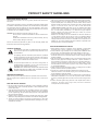
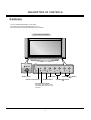
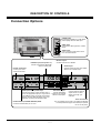
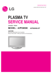
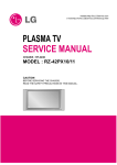
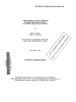
http//www.zenithservice.com
SERVICE MANUAL
Product Type:
Chassis:
Manual Series:
Manual Part #:
Model Line:
Product Year:
Model Series:
P42W46X
PLASMA
RF-043A
P42W46XH
2004
CONTENTS
Description of Controls .................................................4
Product Specifications ..................................................7
Adjustment Instructions ................................................8
Diagrams ...................................................................23
Parts List ...................................................................27
Schematics ....................................................................
Published Oct. 2003
by Technical Publications
LG Electronics USA, Inc.
201 James Record Road,
Huntsville, Alabama 35824-1513
Copyright © 2003 by Zenith Electronics Corporation
Printed in Korea
PRODUCT SAFETY GUIDELINES
IMPORTANT SAFETY NOTICE
This manual was prepared for use only by properly trained audio-visual service
technicians.
When servicing this product, under no circumstances should the original design
be modified or altered without permission from Zenith Electronics Corporation.
All components should be replaced only with types identical to those in the
original circuit and their physical location, wiring and lead dress must conform
to original layout upon completion of repairs.
CAUTION: Do not attempt to modify this product in any way.
Never perform customized installations without manufacturer’s
approval.
Unauthorized modifications will not only void the warranty, but may
lead to property damage or user injury.
Service work should be performed only after you are thoroughly familiar with
these safety checks and servicing guidelines.
5. No lead or component should touch a receiving tube or a resistor rated at 1
watt or more. Lead tension around protruding metal surfaces must be avoided.
6. After reassembly of the set, always perform an AC leakage test on all
exposed metallic parts of the cabinet (the channel selector knobs, antenna
terminals, handle and screws) to be sure that set is safe to operate without
danger of electrical shock. DO NOT USE A LINE ISOLATION
TRANSFORMER DURING THIS TEST. Use an AC voltmeter having 5000
ohms per volt or more sensitivity in the following manner: Connect a 1500
ohm, 10 watt resistor, paralleled by a .15 mfd 150V AC type capacitor
between a known good earth ground water pipe, conduit, etc.) and the
exposed metallic parts, one at a time.
Measure the AC voltage across the combination of 1500 ohm resistor and
.15 mfd capacitor. Reverse the AC plug by using a non-polarized adaptor
and repeat AC voltage measurements for each exposed metallic part.
Voltage measured must not exceed 0.75 volts RMS. This corresponds to 0.5
milliamp AC. Any value exceeding this limit constitutes a potential shock
hazard and must be corrected immediately.
TIPS ON PROPER INSTALLATION
GRAPHIC SYMBOLS
The exclamation point within an equilateral triangle is intended to
alert the service personnel to important safety information in the
service literature.
The lightning flash with arrowhead symbol within an equilateral
triangle is intended to alert the service personnel to the presence
of noninsulated “dangerous voltage” that may be of sufficient
magnitude to constitute a risk of electric shock.
A
V
The pictorial representation of a fuse and its rating within an
equilateral triangle is intended to convey to the service personnel
the following fuse replacement caution notice:
CAUTION: FOR CONTINUED PROTECTION AGAINST RISK
OF FIRE, REPLACE ALL FUSES WITH THE SAME TYPE AND
RATING AS MARKED NEAR EACH FUSE.
SERVICE INFORMATION
While servicing, use an isolation transformer for protection from AC line shock.
After the original service problem has been corrected, make a check of the
following:
FIRE AND SHOCK HAZARD
1. Never install any receiver in a closed-in recess, cubbyhole, or closely fitting
shelf space over, or close to, a heat duct, or in the path of heated air flow.
2. Avoid conditions of high humidity such as: outdoor patio installations where
dew is a factor, near steam radiators where steam leakage is a factor, etc.
3. Avoid placement where draperies may obstruct venting. The customer
should also avoid the use of decorative scarves or other coverings that might
obstruct ventilation.
4. Wall- and shelf-mounted installations using a commercial mounting kit must
follow the factory-approved mounting instructions. A product mounted to a
shelf or platform must retain its original feet (or the equivalent thickness in
spacers) to provide adequate air flow across the bottom. Bolts or screws
used for fasteners must not touch any parts or wiring. Perform leakage tests
on customized installations.
5. Caution customers against mounting a product on a sloping shelf or in a tilted
position, unless the receiver is properly secured.
6. A product on a roll-about cart should be stable in its mounting to the cart.
Caution the customer on the hazards of trying to roll a cart with small casters
across thresholds or deep pile carpets.
7. Caution customers against using a cart or stand that has not been listed by
Underwriters Laboratories, Inc. for use with its specific model of television
receiver or generically approved for use with TVs of the same or larger screen
size.
8. Caution customers against using extension cords. Explain that a forest of
extensions, sprouting from a single outlet, can lead to disastrous
consequences to home and family.
1. Be sure that all components are positioned to avoid a possibility of adjacent
component shorts. This is especially important on items transported to and
from the repair shop.
2. Verify that all protective devices such as insulators, barriers, covers, shields,
strain reliefs, power supply cords, and other hardware have been reinstalled
per the original design. Be sure that the safety purpose of the polarized line
plug has not been defeated.
3. Soldering must be inspected to discover possible cold solder joints, solder
splashes, or sharp solder points. Be certain to remove all loose foreign particles.
4. Check for physical evidence of damage or deterioration to parts and
components, for frayed leads or damaged insulation (including the AC cord),
and replace if necessary.
- 2 -
TABLE OF CONTENTS
DESCRIPTION OF CONTROLS ...........................................4
SPECIFICATIONS.................................................................7
ADJUSTMENT INSTRUCTIONS ..........................................8
TROUBLE SHOOTING GUIDE ...........................................12
BLOCK DIAGRAM...............................................................23
EXPLODED VIEW...............................................................26
EXPLODED VIEW PARTS LIST .........................................27
REPLACEMENT PARTS LIST ............................................28
SCHEMATIC DIAGRAM..........................................................
PRINTED CIRCUIT BOARD ...................................................
- 3 -
DESCRIPTION OF CONTROLS
Controls
- This is a simplified representation of front panel.
Here shown may be somewhat different from your TV.
- This manual explains the features available on the P42W46X.
Front Panel Controls
ON/OFF
TV/VIDEO
ON/OFF Button
MENU
VOL
MENU Button
Remote Control Sensor
TV/VIDEO Button
Power Standby Indicator
Illuminates red in standby mode,
Illuminates green when the TV is
turned on.
- 4 -
CH
CHANNEL (E,
VOLUME (F,G) Buttons
D)
Buttons
DESCRIPTION OF CONTROLS
Connection Options
L / MONO
A/V INPUT2
VIDEO
S-VIDEO
S-VIDEO Input
A connection available to provide better
picture quality than the video input.
VIDEO Input
Connects the video signal from a video
device.
R AUDIO
AUDIO Input
Use to connect to hear stereo sound
from an external device.
Monitor Output
Connect a second TV or Monitor.
DVD/DTV Input (Component 1-2)
Connect a component video/audio
device to these jacks.
S-Video Input
Connect S-Video out from an S-VIDEO
device to the S-VIDEO input.
Remote Control Port
Connect your wired
remote control here.
COMPONENT
INPUT 2
MONITOR
OUTPUT
COMPONENT
INPUT 1
REMOTE
CONTROL
RS-232C INPUT
(CONTROL/SERVICE)
DVI INPUT
AUDIO INPUT
A/V
INPUT 1
R
RGB INPUT
VIDEO
RGB Input/Audio Input/DVI Input
Connect the monitor output connector from a
PC to the appropriate input port. If you want to
use RGB/DVI audio, we strongly recommend
that you use the cable that has a core, or the
EMI filter core along with separate cable.
L
AUDIO
R
L/MONO
AUDIO
S-VIDEO
Antenna
AC INPUT
VIDEO
Audio/Video Input 1
Connect audio/video
output from an external
device to these jacks.
Antenna Input
Connect cable or antenna
signals to the TV, either
directly or through your
cable box.
Power Cord Socket
This TV operates on AC power. The voltage is indicated
on the Specifications page. Never attempt to operate
the TV on DC power.
RS-232C INPUT (CONTROL/SERVICE) PORT
Connect to the RS-232C port on a PC.
- 5 -
DESCRIPTION OF CONTROLS
Remote Control Key Functions
- When using the remote control, aim it at the remote control sensor on the TV.
MUTE
Switches the sound on or off.
TVVIDEO
Selects: TV, Video 1-2, Component
1-2, RGB, and DVI input sources.
MUTE
POWER
TV/VIDEO MULTIMEDIA MTS
CAPTION ARC
MENU
MULTIMEDIA
Selects: Component 1-2, RGB, and
DVI input sources.
CAPTION
Selects CAPTION mode.
VOLUME UP/DOWN
Increases/decreases the sound level. Selects
a menu item.
CHANNEL UP/DOWN
Selects available channels found with Auto
program. Adjusts menu settings.Switches the
set on from standby.
ENTER
Accepts your selection or displays the current
mode.
FCR
Use to scroll the favorite channel list.
APC
Adjusts the factory preset picture according
to the room.
PIP/DW
Switches between PIP and Double
Window modes.
SPLIT ZOOM
Enlarges the picture with regular ration.
POWER
Turns your TV on or off.
MENU
Brings up the main menu to the screen.
CH
ENTER
VOL
MTS
Selects the MTS sound: Mono, Stereo,
or SAP.
VOL
ARC
Changes the picture format.
CH
1
2
3
4
5
6
7
8
FCR
9
NUMBER buttons
REVIEW
Tunes to the last channel viewed.
REVIEW
0
APC PIP/DW
DASP
SPLIT ZOOM PIP CH + SLEEP
DASP
Selects the sound appropriate for the program's character.
SLEEP
Sets the sleep timer.
WIN.SIZE PIP CH - PIP INPUT
POSITION SWAP A.PROG
MEMORY/ERASE
PIPCH-/PIPCH+
Changes to next lower/higher PIP channel.
PIP INPUT
Selects the input source for the sub picture.
A.PROG (AUTO PROGRAM)
Searches for available channels.
WIN. SIZE
Adjusts the sub picture size.
MEMORY/ERASE
Memorizes or erases selected channel.
POSITION
Moves the sub picture in pip mode.
SWAP
Exchanges the main/sub images.
- 6 -
SPECIFICATIONS
MODEL
P42W46X
Width (inches / mm)
48.4 / 1210
Height (inches / mm)
27.6 / 701
Depth (inches / mm)
11.4 / 290
Weight (pounds / kg)
66 / 22.9
Resolution
852 x 480 (Dot)
Power requirement
AC100-240V, 60Hz
Television System
NTSC
Program Coverage
VHF 2 ~ 13, UHF 14 ~ 69, CATV 1 ~ 125
External Antenna Impedance
75 Ω
Color
16,770,000 (256 steps of each R, G and B)
Operating Temperature Range
32 ~ 104°F (0 ~ 40°C)
Operating Humidity Range
Less than 80%
Maximum Elevation
6561 feet (2000m)
• The specifications shown above may be changed without notice for quality improvement.
- 7 -
ADJUSTMENT INSTRUCTIONS
(2) After installing the Gprobe, [Option -> Connection Setup]
or click the icon indicated in the picture and then setup as
below the picture.
(In case of the port (second one), set to the serial port
of the connected PC.
The other only have to be set as below the picture.)
(3) After finishing inputs, click the button [OK] to complete the
connection setup.
1. Application Object
These instructions apply to the RF-043A Chassis.
2. Specification
(1) Because this is not a hot chassis, it is not necessary to
use an isolation transformer. However, the use of isolation
transformer will help protect test instrument.
(2) Adjustment must be done in the correct order.
(3) The adjustment must be performed in the circumstance of
25±5°C of temperature and 65±10% of relative humidity if
there is no specific designation.
(4) The input voltage of the receiver must keep 100~220V,
50/60Hz.
(5) The receiver must be operated for about 15 minutes prior
to the adjustment.
3-2. Confirming the G-prove
(1) Connect Rs232 cable and then turn on the power.
If communication is correct, the message is showed like in
the left output terminal.
(2) If the message is not showed, push the [INSTART] button
of the adjust remocon twice, and change the right selection
of the [System Control -> RS-232 Host] from GProbe to
PC.
** If it is impossible to check the OSD, push the [TILT]
button of the adjust remocon.
Then, the message which is “Starting Gprove...”
comes up. From this time, communication is operated
correctly.
However, you have to push the [TILT] button again
in case of turning on Main Power.
** If you want to check again whether commnunication is
on or not, input “test” and push the Enter key on the
right input terminal. If communication is on, the
message of “Test passed.” will come up
After RGB Full white HEAT-RUN Mode, the receiver must
be operated prior to adjustment.
O Enter into HEAT-RUN MODE
1) Press the POWER ON KEY on R/C for adjustment.
2) OSD display and screen display 100% full WHITE
PATTERN.
O
[ Set is activated HEAT-RUN without signal generator in
this mode.
[ Single color pattern(RED/BLUE/GREEN) of HEAT-RUN
mode uses to check PANEL.
Caution) If you turn on a still screen more than 20 minutes
(Especially digital pattern, cross hatch pattern), a after
image may be occur in the black level part of the
screen.
3. Channel memory
3-1. Setting up the G-prove
(Fig 2)
3-3. Channel memory method
(1) Click [Command -> Batch].
(2) When the window of [Batch] is showed, enter the text file
(Ch_Memory-RZ_PX10.txt) in the right blank of the File.
(3) Click the button [OK] to write CH information in the
EEPROM.
(4) It means the completion of the CH memory download that
the message of right output terminal is showed as below.
(Fig 1)
(1) Install the GProve. (GProve4.4.0.2.exe)
- 8 -
ADJUSTMENT INSTRUCTIONS
Each PCB assembly must be checked by check JIG set.
(Because power PCB Assembly damages to PDP Module,
especially be careful)
5. POWER PCB Assy Voltage
Adjustments (Va, Vs Voltage Adjustments)
5-1. Test Equipment : D.M.M. 1EA
5-2. Connection Diagram for Measuring
Refer to Fig 5.
(Fig 3)
4. HDCP download
4-1. Setting up & Confirming the G-prove
: Refer to 3-1 and 3-2.
4-2. HDCP download method
(1) Click [Command -> NVRAM Write]
(2) When the window of [NVRAM Write] is showed, select
“LGEKEY1.bin” to insert fill up in the File.
(3) LGEKEY1 : first KEY value
(4) Address : insert ‘0’
(5) After finishing inputs, click the button [OK] to write HDCP
key in the EEPROM.
(6) It means the end of the HDCP key download that the
message of Output terminal is showed as below.
< 3501V00180A >
< 3501V00182A >
(Fig 5) Connection Diagram of power adjustment for measuring
(Fig 4)
5-3. Adjustment Method for
P/No. 3501V00180A B/D
(1) Va Adjustment
1) After receiving 100% Full White Pattern, HEAT RUN.
2) Connect + terminal of D.M.M to Va pin of P805, connect
- terminal to GND pin of P805.
3) After turning RV501, voltage of D.M.M adjustment as
same as Va voltage which on lable of panel right/top
(Deviation; ±0.5V)
(2) Vs Adjustment
1) Connect + terminal of D.M.M to Vs pin of P805, connect
– terminal to GND pin of P805.
- 9 -
ADJUSTMENT INSTRUCTIONS
(2) Supply Gray Pattern (216 Level Full Size Pattern) signal
to VIDEO input. (AV2 Input 60Hz)
(Refer to Fig. 6)
(3) To adjust, stick sensor to 216 Gray Level Pattern, press
ADJ key twice(White Balance) on remote control.
For adjustment and D, E on reomte control for adjustment
mode to select Red Gain and Blue Gain, press VOL +, Key and adjust it until color coordination becomes as
below.
2) After turning RV401, voltage of D.M.M adjustment as
same as Va voltage which on label of panel right/top.
(Deviation; ±0.5V)
5-4. Adjustment Method for
P/No. 3501V00182A B/D
(1) Va Adjustment
1) After receiving 100% Full White Pattern, HEAT RUN.
2) Connect + terminal of D.M.M to Va pin of P805, connect
- terminal to GND pin of P805.
3) After turning RV601, voltage of D.M.M adjustment as
same as Va voltage which on lable of panel right/top
(Deviation; ±0.5V)
X; 0.283±0.003, Y; 0.297±0.003
Color Temperature; 9,300°K±500°K
(4) Exit adjustment mode using A Key.
(2) Vs Adjustment
1) Connect + terminal of D.M.M to Vs pin of P805, connect
– terminal to GND pin of P805.
2) After turning RV401, voltage of D.M.M adjustment as
same as Va voltage which on label of panel right/top.
(Deviation; ±0.5V)
7. Auto RGB Color Balance
7-1. Pattern Equipment
PC Pattern Generator (VG828, VG854, 801GF, MSP3240A)
(16 Gray Scale Pattrtn output(RGB output Level: 0.7Vp-p)
7-2. Method of Auto RGB Color Balance
6. Adjustment of White Balance
(1) Input RGB Source : 16 Gray Scale Pattern output (RGB
output Level : 0.7Vp-p)
(2) Press ADJ KEY on R/C for adjustment.
(3) Press Vol. + KEY and operate To SET.
(4) Auto-RGB OK means completed adjustment.
6-1. Required Equipment
Color Analyzer (CA-100 or same product)
6-2. Connection Diagram of Equipment for
Measuring
8. Auto Component Color Balance
216 Gray Level
8-1. Pattern Equipment
AV Signal Input
MSP3240A or same product
(16 Gray Scale Pattern output(Component output Level:
0.7Vp-p)
Full Size Pattern
60Hz
Window
8-2. Method of Auto RGB Color Balance
RS-232C Serial Communication
(1) Input RGB Source : Component 480p/576p 16 Gray Scale
Pattern
At this time, except Pb and Pr signal, only Y signal insert.
(2) Press ADJ KEY on R/C for adjustment.
(3) Press Vol. + KEY and operate To set.
(4) Auto-RGB OK means completed adjustment.
MSPG-2100 or
MSTG-5200
(Fig 6) White Balance Adjustment
6-3. Adjustment of White Balance
O
O
Operate the Zero-calibration of the CA-100, then stick
sensor to PDP module surface when you adjust.
For manual adjustment, it is also possible by the following
sequence.
(1) Select white pattern of heat-run mode by pressing power
on key on remote control for adjustment then operate heat
run more than 15 minutes.
(Fig 7) Auto RGB/ Component Color Balance Test Pattern
- 10 -
ADJUSTMENT INSTRUCTIONS
9. Auto Adjustment Map(RS-232C)
6) If Check Sum is not 53, repeat 3) ~ 4).
7) If Check Sum is 53, DDC data for Analog-RGB input is
completed.
RF-043A
Type
RS232
(2) DDC Data input for Digital-RGB(DVI)
Baud Rate
Data bit
Stop bit
Parity
115200
8
1
NONE
Index Cmd1 Cmd2 Data Min Value Max Value
R Gain
j
a
00(00)
255(FF)
G Gain
j
b
00(00)
255(FF)
Protocol B Gain
Setting
R Offset
j
c
00(00)
255(FF)
j
d
00(00)
255(FF)
G Offset
j
e
00(00)
255(FF)
B Offset
j
f
00(00)
255(FF)
10. DDC Data Input
10-1. Required Test Equipment
(1) A jig for adjusting PC, DDC (PC serial to D-sub
Connection equipment)
(2) S/W for writing DDC (EDID Data Write & Read)
(3) D-sub 15P Cable, D-Sub to DVI Connector (Connect to
DVI Jack)
10-2. Setting of Device
10-3. Preparation for Adjustment
(1) Set devices as above and turn the PC, jig on.
(2) Put S/W for writing DDC (EDID data Write & Read) into
operation. (operated in DOS mode.)
10-4. Sequence of Adjustment
(1) DDC Data Input for Analog-RGB
1) Put the set on the table and turn the power on.
2) Connect PC Serial to D-sub 15P Cable of jig for DDC
adjustment to RGB terminal (D-Sub 15Pin).
3) Operate S/W for DDC record and select DDC data for
Analog RGB in Model Menu.
4) Operate EDID Write command.
5) Operate EDID Read command and check whether
Check Sum is 53.
- 11 -
1) Connect PC Serial to DVI Cable of jig for DDC
adjustment to DVI terminal (DVI Jack).
2) Operate S/W for DDC record and select DDC data for
digital RGB in model menu.
3) Operate EDID Write command.
4) Operate EDID Read command and check whether
Check sum is D2(1page), BF(2page).
5) If Check sum is not D2(1page), BF(2page), repeat 3) ~
4).
6) If Check sum is D2(1page), BF(2page), DDC data for
Analog-RGB input is completed.
TROUBLE SHOOTING GUIDE
1. Power Board
1-1. The whole flowchart which it follows in voltage output state
Start check
Doesn't the
screen whole come
out?
Yes
It is identical
with Power Off
condition?
No
Is the Interface
signal operated?
Yes
No
Doesn't the
low pressure output
come out?
Yes
1. Check the Power Off
condition.
Yes
Doesn't the
St-by 5V signal
come out?
2. Check the Interface
signal condition.
Doesn't the
5V Monitor signal
come out?
No
Yes
No
Doesn't the
high tension output
come out?
Yes
3. Check the St-by 5V
signal circuit.
Yes
Doesn't the
VSC signal Vs-ON
come out?
High tension
output voltage Drop
it occurs?
Yes
5. Check the VSC RL-ON
signal.
Doesn't the
Vs, Va voltage output
come out?
No
Doesn't the
VSC low pressure
output come out?
Yes
7. Check the VSC Vs-ON
signal
When remove
the Y, Z B/D Module
Input Connector, Power
Board high tension output
voltage Drop
it occurs?
Yes
4. Check the 5V Monitor
signal circuit.
Yes
No
Doesn't the
VSC signal RL-ON
come out?
No
Yes
8. Check the Vs, Va
voltage output circuit.
No
No
When
remove the
Y B/D Module
Input Connector, output
voltage Drop
it occurs?
6. Check the VSC low
pressure output
No
When
remove the
Z B/D Module
Input Connector, output
voltage Drop
it occurs?
No
Yes
Manufacture enterprise
meaning of a passage
Yes
10. Check the Z B/D
Module Coutput circuit
9. Check the Power
Board Output high
tension circuit
- 12 -
Yes
11. Check the Y B/D
Module Coutput circuit
TROUBLE SHOOTING GUIDE
1-2. Sony Power Board Structure
T502: Vs Trans
T702: Va Trans
1
2
3
T101: St-by Trans
T103: Low Voltage Trans
- 13 -
TROUBLE SHOOTING GUIDE
1-3. Sanken Power Board Structure
T221: Vs Trans
T271: Va Trans
1
2
3
T121: St-by Trans
T201: Low Voltage Trans
- 14 -
TROUBLE SHOOTING GUIDE
2. No Power
(1) Symptom
¯
¯
Does’t minute discharge at module.
Non does not come in into the front LED.
(2) Check follow
No
Is plug in power cord?
Plug in power cord.
Yes
Is connect the Line Filter and Power
Switch Cable?
No
Connect Cable.
Yes
Is connect the Power Switch and
Power Board Cable?
No
Connect Cable.
Yes
Is normal the Fuse(F101) on Power
Board?
No
Replace Fuse.
Yes
Is connect the Power Board and 7P
of VSC Board Cable?
No
Connect Cable.
Yes
Is connect the Power Switch and
Power Board Cable?
No
Connect Cable.
Yes
After remove the cable connect to
Power Board(except the CN101
connection cable), authorizes the
AC voltage marking on manual.
When ST-BY 5V does not operate,
replace Power Board.
- 15 -
TROUBLE SHOOTING GUIDE
3. Protect Mode
(1) Symptom
After once shining, it does not discharge minutely
from module
¯ The Rely falls(The sound is audible “click”)
¯ It is converted with the color where the front LED
is red from green.
¯
(2) Check follow
Is normal the Power
Board?
No
Is output the normality Low/High
voltage except Stand-by 5V?
No
Replace Power
Board.
Yes
Is normal the each
connector?
No
After connecting well each connector,
the normality it operates?
No
Replace
connector.
Yes
Is normal the
Y- Board?
No
Is normal the Fuse(F52) on Y-B/D?
(In case of open is replace)
Yes
Is normal the output
voltage after remove
P5, P6 connector of
Y-B/D?
Yes
Replace
Y-Board.
Yes
Replace
Z-Board.
Yes
Is normal the
Z- Board?
No
Is normal the Fuse(FS1, FS2) on ZB/D? (In case of open is replace)
Yes
Is normal the output
voltage after remove
P1 connector of
Z-B/D?
Yes
Is normal the
X- Board?
No
Is normal the output voltage after
remove P1, 2, 3, 4, 6, 7 connector of
X-B/D?
Yes
No
Is normal the output voltage after
remove P1, 2, 101, 300, 701, 702
connector of Ctrl-B/D?
Yes
After remove P1, P2, P3, P4 output voltage
normality: Replace Right X-B/D
After remove P6, P7 output voltage
normality: Replace Left X-B/D
Yes
Is normal the
Ctrl Board?
Replace
X-Board.
Yes
Is normal the
VSC Board?
No
Is normal the output voltage after
remove P1000, P1200?
Yes
After remove P1000 normal operation:
Replace Analog Board
After remove P1200 normal operation:
Replace Digital Board
Yes
Is normal the
COF of X, Y, Z?
No
After crisis COF of each board, check the normality operates.
If in case normality operates, correspondence COF Fail is
replace the module.
- 16 -
TROUBLE SHOOTING GUIDE
4. No Raster
(1) Symptom
¯
¯
Does’t minute discharge at module.
It maintains the condition where the front LED is green.
(2) Check follow
Is normal the Power
Board?
No
Is output the normality Low/High
voltage except Stand-by 5V?
No
Replace Power
Board.
Yes
Is normal the each
connector?
No
After connecting well each connector,
the normality it operates?
No
Replace
connector.
Yes
Is normal the
Y- Board?
No
Is normal the Fuse(F52) on Y-B/D?
(In case of open is replace)
Yes
Is normal the output
voltage after remove
P5, P6 connector of
Y-B/D?
Yes
Replace
Y-Board.
Yes
Replace
Z-Board.
Yes
Is normal the
Z- Board?
No
Is normal the Fuse(FS1, FS2) on ZB/D? (In case of open is replace)
Yes
Is normal the output
voltage after remove
P1 connector of
Z-B/D?
Yes
Is normal the
X- Board?
No
Is normal the output voltage after
remove P1, 2, 3, 4, 6, 7 connector of
X-B/D?
Yes
No
Is normal the output voltage after
remove P1, 2, 101, 300, 701, 702
connector of Ctrl-B/D?
Yes
After remove P1, P2, P3, P4 output voltage
normality: Replace Right X-B/D
After remove P6, P7 output voltage
normality: Replace Left X-B/D
Yes
Is normal the
Ctrl Board?
Replace
X-Board.
Yes
Is normal the
VSC Board?
No
Is normal the output voltage after
remove P1000, P1200?
Yes
After remove P1000 normal operation:
Replace Analog Board
After remove P1200 normal operation:
Replace Digital Board
Yes
Is normal the
COF of X, Y, Z?
No
After crisis COF of each board, check the normality operates.
If in case normality operates, correspondence COF Fail is
replace the module.
- 17 -
TROUBLE SHOOTING GUIDE
5. In case of occur strange screen into specific mode
5-1. In case of does’t display the OSD
(1) Symptom
¯
¯
LED is green
The minute discharge continuously becomes
accomplished from module
(2) Check follow
Is normal the LVDS
cable?
No
Yes
Is the LVDS cable
connected well?
Replace cable.
No
Cable inserts well.
Yes
Is normal the VSC
Digital Board?
No
Operates the Thine Yes
IC(IC1100)?
Operates the
IEP(IC500)?
No
Replace Thine
IC(IC1100).
Yes
Is normal the Ctrl
Board of Module?
No
Replace
IEP(IC500).
No
Replace Ctrl B/D.
- 18 -
Yes
Operates the
Scaler(IC700)?
No
Replace
Scaler(IC700).
Yes
Replace
VSC Digital
B/D.
TROUBLE SHOOTING GUIDE
5-2. In case of does’t display the screen into specific mode
(1) Symptom
¯
The screen does not become the display from specific input mode
(RF, AV, Component, RGB, DVI).
(2) Check follow
¯
¯
Check the all input mode should become normality display.
Check the Video(Main)/Data(Sub), Video(Main)/Video(Sub) should become
normality display from the PIP mode or DW mode. (Re-Check it Swap)
(3) In case of becomes unusual display from RF mode
No
Is normal the Tuner?
Is the Tuner Cable
connected well?
Yes
Is normal the Input voltage, IIC
Communication and CVBS output?
No
No
Yes
Cable inserts well.
Is normal the
CXA2069Q?
No
Replace Tuner
Is normal the Input voltage, IIC
Communication and HV sync?
No
Is normal the Input voltage, IIC
Communication and HV sync?
No
Replace IC
Yes
Is normal the
VPC3230?
No
Replace IC
(4) In the case of becomes unusual display from RF, AV mode
Is normal the
CXA2069Q?
No
Is normal the Input voltage, IIC
Communication and HV sync?
No
Is normal the Input voltage, IIC
Communication and HV sync?
No
Replace IC
Yes
Is normal the
VPC3230?
No
- 19 -
Replace IC
TROUBLE SHOOTING GUIDE
(5) In the case of becomes unusual display from RF, AV, Component 480i mode
Is normal the
VPC3230?
No
Is normal the Input voltage, IIC
Communication and HV sync?
No
Is normal the Input voltage, IIC
Communication and HV sync?
No
Is normal the Input voltage, IIC
Communication and HV sync?
No
Replace IC
Yes
No
Is normal the S2300?
Replace IC
Yes
No
Is normal the Scaler?
Replace IC
(6) In the case of becomes unusual display from Component DTV mode
Is normal the
74LS123?
No
Is normal the Input voltage, IIC
Communication and HV sync?
No
Is normal the Input voltage, IIC
Communication and HV sync?
No
Is normal the Input voltage, IIC
Communication and HV sync?
No
Is normal the Input voltage, IIC
Communication and HV sync?
No
Replace IC
Yes
Is normal the
CXA2101?
No
Replace IC
Yes
Is normal the
M52758?
No
Replace IC
Yes
No
Is normal the Scaler?
- 20 -
Replace IC
TROUBLE SHOOTING GUIDE
(7) In the case of becomes unusual display from RGB DTV mode
Is normal the
CXA2101?
No
Is normal the Input voltage, IIC
Communication and HV sync?
No
Is normal the Input voltage, IIC
Communication and HV sync?
No
Is normal the Input voltage, IIC
Communication and HV sync?
No
Replace IC
Yes
Is normal the
M52758?
No
Replace IC
Yes
No
Is normal the Scaler?
Replace IC
(8) In the case of becomes unusual display from RGB PC mode
Is normal the
M52758?
No
Is normal the Input voltage, IIC
Communication and HV sync?
No
Is normal the Input voltage, IIC
Communication and HV sync?
No
Replace IC
Yes
No
Is normal the Scaler?
Replace IC
(8) In the case of becomes unusual display from DVI mode
No
Is normal the Scaler?
Is normal the Input voltage, IIC
Communication and HV sync?
- 21 -
No
Replace IC
TROUBLE SHOOTING GUIDE
6. In case of no sound
(1) Symptom
¯
¯
LED is green
Screen display but sound is not output
(2) Check follow
Is normal the SPK
cable?
No
Is the SPK cable
connected well?
Yes
Replace SPK cable
No
Yes
Is normal the
RGB/DVI sound?
Cable inserts well.
No
Is the Flat cable
connected well?
Yes
No
No
Cable inserts well.
Yes
Yes
Operates the IC800?
Replace IC800
Operates the IC801?
No
Replace IC801
Yes
Is normal the
RF/AV/Component
sound?
No
Replace
VSC Analog B/D
Operates the IC802?
No
Replace IC802
- 22 -
- 23 -
24LC21
RX/ TXC
24LC21
74HCT08
Co mp _Y
YCin4
Vin4
TU_Sub
TU_Main
Text _V
Main_YC
HYV641620
SRAM
SDA6001
Text Processor
VPC3230 (S)
Video Decoder
VPC3230 (M )
Video Decoder
Sid e - AV BOARD
Co mp _480i
CVBS S-VHS
Vin5 YCin5
CXA2069Q
SWITCH
Main_V
Main_YC
Main_V
M52758F
Sw it c h
RGB_Dat a
AM29LV160
F-ROM
HY57V64322
SDRAM ( 8MB)
YCb Cr
S2300
/
DeInt erlac er
8
DVI_Dat a
g m 1601
Sc aler ( Malib u)
ADC
w/ PLL
10
24
ZHINE
Po s-t p ro c es sing Blo c k is o m it t ed .
so-c alled JEPICO, in this c ase
TMDS TX is also req uired .
So und Pro c es sing Blo c k Diag ram
is sep arat ed . .
RCA-t yp e Blo c k Diag ram is also
sep arat ed . .
AM29LV
F-ROM (1MB )
IEP
TX0/ 1/ 2/ 3/ C
Disp _En
SDATA
SCLK, SLE
24
Co mp _480I/ P
Co mp
/ RGB_SW
HY5DU283222A
SDRAM ( 128MB)
DVI RX
w/ HDCP
RS232_RX/ TX
TX_Out
Main_Vid eo
/
24
Sub _Vid eo
/
Co mp / RGB_SW
8
Fro m Malib u
CXA_RGB
Vid eo f o r Text
CXA2101
Text
Comp DTV
RGB DTV
RGB PC
Co mp _480I/ P
To Malib u
74LS123
Tuner ( S )
Tuner (M)
Vin3 (CVBS )
MNT OUT
Vin2 ( CVBS )
1H RGB
TV OUT
Vin1 ( CVBS)
SCL/ SDA
RX/ TX0/ 1/ 2,
SCL/ SDA
RGB H/ V
Analo g BOARD
Comp1
(DVD/DTV )
S-VHS
CVBS
RF
Scart 3
Scart 2
Scart 1
ST3232C
74ACT253
RGB PC/ DTV
RX0/1,TX0/1
Dig it al BOARD
DVI
(PC/DTV)
RGB
(PC/DTV)
RS232
WIRE IR
TX
IR
BLOCK DIAGRAM
IIS
RGB DTV
IIS
HV
IIS
Tx
- 24 -
Sid e
S-VHS
Side-CVBS
Sid e A/ V
RF
S-VHS
CVBS OUT
CVBS IN
( DVD/ DTV)
Co m p 2
( DVD/ DT V)
Co m p 1
24LC21
24LC21
Y/ CIN2
VIN2
Tuner ( S)
CXA2069Q
74HCT08
ST3232C
74ACT253
Tuner ( M)
Y/ CIN1
MNT_OUT
VIN1
Co mp 2
Co mp
Analo g BOARD
DVI
( PC/ DTV)
RGB
( PC/ DTV)
RS232
WIRE IR
Di gt a l BOARD
MAIN_YOUT
MAIN_VOUT
MAIN_COUT
CAB_VIN
DTV2_Co mp
DAC_RGB
RGB_DTV
M52758FP
IC202( MUX)
LA7151M
DVD2_MAIN
DVD_MAIN
DTV_Co mp
M52758FP
IC204
CXA2101
RGB PC
SUB_COUT
SUB_YOUT
DVD2_SUB
DVD_SUB
ALT_Y2_480I_SUB
VPC3230
( SUB)
COMB_COUT
SW CVBS/ Y
ALT_Y_480I_SUB
UPD64083
COMB_YOUT
MAIN_YOUT
ALT_Y2_480I_MAIN
M62320FP
( I2C Exp end er)
HY57V64322
SDRAM ( 8MB)
Flash ROM
512K/ 1M
TQFP 128K
DDR Memo ry
M656 8 Bit
FLI2300
S656 8 Bit
VPC3230
( MAIN)
S/ DVD_Co mp
CAB_Co mb
RGB_24Bit
SVPORT
( 16b it)
g m1501H
ALT_Y_480I_MAIN
M52758FP
IC400( MUX)
M37136
( OTP)
VPORT
( 24b it)
DVI
Analo g
RGB
TMDS Transf er
/ Thine
LVDS
31PIN
ZHINE
IEP
BLOCK DIAGRAM
NOTES
- 25 -
EXPLODED VIEW
300
121
600
601
301
305
304
120
303
302
200
207
202
206
205
530
201
490
204
531
402
580
203
560
410