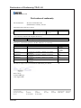
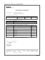
1
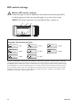
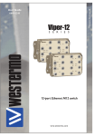
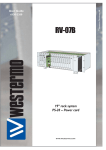
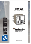
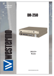
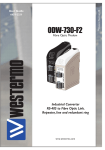
6600-2204 TD-23 Leased Line V.23 Modem Multidrop applications www.westermo.com © Westermo Teleindustri AB User Guide Legal information The contents of this document are provided “as is”. Except as required by applicable law, no warranties of any kind, either express or implied, including, but not limited to, the implied warranties of merchantability and fitness for a particular purpose, are made in relation to the accuracy and reliability or contents of this document. Westermo reserves the right to revise this document or withdraw it at any time without prior notice. Under no circumstances shall Westermo be responsible for any loss of data or income or any special, incidental, and consequential or indirect damages howsoever caused. More information about Westermo can be found at the following Internet address: http://www.westermo.com 2 6600-2204 Safety ! Before installation: This modem is for restricted access area use only. Read this manual completely and gather all information on the unit. Make sure that you understand it fully. Check that your application does not exceed the safe operating specifications for this unit. This unit should only be installed by qualified personnel. This unit should be built-in to an apparatus cabinet, or similar, where access is restricted to service personnel only. The power supply wiring must be sufficiently fused, and if necessary it must be possible to disconnect manually from the power supply. Ensure compliance to national installation regulations. This unit uses convection cooling. To avoid obstructing the airflow around the unit, follow the spacing recommendations (see Cooling section). ! Before mounting, using or removing this unit: Prevent access to hazardous voltage by disconnecting the unit from power supply. Warning! Do not open connected unit. Hazardous voltage may occur within this unit when connected to power supply. Care recommendations Follow the care recommendations below to maintain full operation of unit and to fulfil the warranty obligations. This unit must not be operating with removed covers or lids. Do not attempt to disassemble the unit. There are no user serviceable parts inside. Do not drop, knock or shake the unit, rough handling above the specification may cause damage to internal circuit boards. Do not use harsh chemicals, cleaning solvents or strong detergents to clean the unit. Do not paint the unit. Paint can clog the unit and prevent proper operation. Do not expose the unit to any kind of liquids (rain, beverages, etc). The unit is not waterproof. Keep the unit within the specified humidity levels. Do not use or store the unit in dusty, dirty areas, connectors as well as other mechanical part may be damaged. If the unit is not working properly, contact the place of purchase, nearest Westermo distributor office or Westermo Tech support. Maintenance No maintenance is required, as long as the unit is used as intended within the specified conditions. 6600-2204 3 Agency approvals and standards compliance Type Approval / Compliance EMC EN 61000-6-2, Immunity industrial environments EN 55024, Immunity IT equipment EN 61000-6-3, Emission residential environments FCC part 15 Class B EN 50121-4, Railway signalling and telecommunications apparatus IEC 62236-4, Railway signalling and telecommunications apparatus Safety EN 60950-1, IT equipment FCC Part 15.105 Notice:This equipment has been tested and found to comply with the limits for a Class B digital device, pursuant to Part 15 of the FCC Rules. These limits are designed to provide reasonable protection against harmful interference in a residential installation. This equipment generates, uses and can radiate radio frequency energy and, if not installed and used in accordance with the instructions, may cause harmful interference to radio communications. However, there is no guarantee that interference will not occur in a particular installation. If this equipment does cause harmful interference to radio or television reception, which can be determined by turning the equipment off and on, the user is encouraged to try to correct the interference by one or more of the following measures: … Reorient or relocate the receiving antenna … Increase the separation between the equipment and receiver … Connect the equipment into an outlet on a circuit different from that to which the receiver is connected … Consult the dealer or an experienced radio/TV technician for help. 4 6600-2204 Declaration of Conformity, TD-23 LV Westermo Teleindustri AB Declaration of conformity The manufacturer Westermo Teleindustri AB SE-640 40 Stora Sundby, Sweden Herewith declares that the product(s) Type of product Leased Line V.23 Modem Model TD-23 LV TD-23 LV (relay option) Art no 3600-2001 3600-2051 is in conformity with the following EC directive(s). No Short name 2004/108/EC Electromagnetic Compatibility (EMC) References of standards applied for this EC declaration of conformity. No EN 55022 Title Information technology equipment - Emission EN 55024 Information technology equipment - Immunity EN 61000-6-1 Electromagnetic compatibility – Immunity for residential environments Electromagnetic compatibility – Immunity for industrial environments Electromagnetic compatibility – Emission for residential environments Electromagnetic compatibility – Emission for industrial environments EN 61000-6-2 EN 61000-6-3 EN 61000-6-4 The last two digits of the year in which the CE marking was affixed: Issue 2006 +A1:2007 1998 +A1:2001 +A2:2003 2007 2005 2007 2007 10 Pierre Öberg Technical Manager 31th August 2010 Postadress/Postal address Tel. Telefax Postgiro Bankgiro Org.nr/ Corp. identity number Registered office S-640 40 Stora Sundby Sweden 016-428000 Int+46 16428000 016-428001 Int+46 16428001 52 72 79-4 5671-5550 556361-2604 Eskilstuna 6600-2204 5 Declaration of Conformity, TD-23 HV Westermo Teleindustri AB Declaration of conformity The manufacturer Westermo Teleindustri AB SE-640 40 Stora Sundby, Sweden Herewith declares that the product(s) Type of product Leased line V.23 modem Model TD-23 HV TD-23 HV (relay option) Art no 3600-2101 3600-2151 is in conformity with the following EC directive(s). No Short name 2004/108/EC 2006/95/EC Electromagnetic Compatibility (EMC) Low Voltage (LVD) References of standards applied for this EC declaration of conformity. No EN 55022 Title Information technology equipment - Emission EN 55024 Information technology equipment EN 61000-6-1 Electromagnetic compatibility – Immunity for residential environments Electromagnetic compatibility – Immunity for industrial environments Electromagnetic compatibility – Emission for residential environments Electromagnetic compatibility – Emission for industrial environments Information technology equipment – Safety – General requirements EN 61000-6-2 EN 61000-6-3 EN 61000-6-4 EN 60950-1 - Immunity The last two digits of the year in which the CE marking was affixed: Issue 2006 +A1:2007 1998 +A1:2001 +A2:2003 2007 2005 2007 2007 2006 + A1:2006 + A11:2009 11 Pierre Öberg Technical Manager 8th July 2011 6 Postadress/Postal address Tel. Telefax Postgiro Bankgiro Org.nr/ Corp. identity number Registered office S-640 40 Stora Sundby Sweden 016-428000 Int+46 16428000 016-428001 Int+46 16428001 52 72 79-4 5671-5550 556361-2604 Eskilstuna 6600-2204 Type tests and environmental conditions Electromagnetic Compatibility Phenomena Test Description Test levels ESD EN 61000-4-2 Enclosure contact ± 6 kV Enclosure air ± 8 kV RF field AM modulated IEC 61000-4-3 Enclosure 6 V/m 80% AM (1 kHz) 2000 – 2700 MHz 10 V/m 80% AM (1 kHz), 80 – 1000 MHz 20 V/m 80% AM (1 kHz), 80 – 2000 MHz RF field 900 MHz ENV 50204 Enclosure 20 V/m pulse modulated 200 Hz, 900 ± 5 MHz Fast transient EN 61000-4-4 Signal ports ± 2 kV Power ports ± 2 kV Signal ports unbalanced ± 2 kV line to earth, ± 2 kV line to line Signal ports balanced ± 2 kV line to earth, ± 1 kV line to line Power ports ± 2 kV line to earth, ± 2 kV line to line Signal ports 10 V 80% AM (1 kHz), 0.15 – 80 MHz Power ports 10 V 80% AM (1 kHz), 0.15 – 80 MHz Surge RF conducted EN 61000-4-5 EN 61000-4-6 Power frequency magnetic field EN 61000-4-8 Enclosure 100 A/m, 50 Hz, 16.7 Hz & 0 Hz Pulse magnetic field EN 61000-4-9 Enclosure 300 A/m, 6.4 / 16 µs pulse Voltage dips and interruption EN 61000-4-11 AC power ports 10, 20, 5000 ms interruption 10 & 500 ms, 30% reduction 200 ms, 60% reduction Mains freq. 50 Hz EN 61000-4-16 Signal ports 100 V 50 Hz line to earth Mains freq. 50 Hz SS 436 15 03 Signal ports 250 V 50 Hz line to line Voltage dips and interruption EN 61000-4-29 DC power ports 10 & 100 ms, interruption 500 ms, 30% reduction 10 ms, 60% reduction +20% above & –20% below rated voltage Radiated emission EN 55022 Enclosure Class B FCC part 15 Conducted emission Class B EN 55022 AC power ports Class B FCC part 15 AC power ports Class B EN 55022 DC power ports Class B EN 60950 Signal port to other isolated ports 2 kVrms 50 Hz 1 min Power port to other isolated ports 3 kVrms 50 Hz 1 min 2 kVrms 50 Hz 1 min (@ rated power <60 V) Operating –25 to +70°C Storage & Transport –30 to +70°C Operating 5 to 95% relative humidity Storage & Transport 5 to 95% relative humidity Altitude Operating 2 000 m / 70 kPa Service life Operating 10 year Dielectric strength Environmental Temperature Humidity Vibration IEC 60068-2-6 Operating 7.5 mm, 5 – 8 Hz 2 g, 8 – 500 Hz Shock IEC 60068-2-27 Operating 15 g, 11 ms UL 94 PC / ABS Flammability class V-1 Packaging Enclosure Dimension W x H x D 55 x 100 x 132 mm Weight Degree of protection 0.25 kg IEC 529 Enclosure IP 20 Cooling Convection Mounting Horizontal on 35 mm DIN-rail 6600-2204 7 Description TD-23 is designed to satisfy industry's demands on reliability and functionality in environments with high levels of interference.TD-23 communicates via a 2- or 4-wire leased line according to the V.23 standard. Equipment with an RS-232 or RS-422/485 interface can be connected and communicate point-to-point or in a multidrop application.The modem is equipped with DIP-switches to set specific functions in hardware, for example, reception sensitivity, output signal level, etc. This is of particular importance as it allows each modem to be optimised according to the line quality. A general calculation allows 16 units over a distance of up to 25 km (15.5 miles). TD-23 is intended for mounting on a 35 mm DIN-rail, where the modem is attached and locked in a single action. … Data rate 1200 bit/s (V.23) … 2-wire (half duplex), 4-wire (full duplex) … Number of multidrop points, 16 (typical value) … Transmission distance up to 25 km (15.5 miles) … Adjustable output signal level … Adjustable reception sensitivity … Transient protection on the line side … AC-/DC-supply … Galvanic isolation (line/supply) … Optional relay output reflecting the transmitter carrier 8 6600-2204 Functional description Block diagram Modulated data VCC Line relay 2 or 4-wire GND Selectable output level Selectable input sensitivity Modem Analog filter Frequency modulation Frequency demodulation DIP-switches Processor Data buffer Data buffer Modem chip control OR GND 6600-2204 DSR RTS CTS DCD RD TD TD RD RS-232 RS-422/485 GND Relay output 9 Interface specifications Power LV Rated voltage Operating voltage Rated current Rated frequency Inrush current I²t Startup current* Polarity Isolation to Connection Connector size Shielded cable Power HV Rated voltage Operating voltage Rated current Rated frequency Inrush current I²t Startup current* Polarity Isolation to Connection Connector size Shielded cable 12 to 48 VDC 12 to 27 VAC 10 to 60 VDC 10 to 30 VAC 125 mA @ 12 VDC 50 mA @ 24 VDC 28 mA @ 48 VDC 125 mA @ 12 VAC 50 mA @ 24 VAC 25 mA @ 32 VAC DC / AC 48 – 62 Hz 0.09 A²s 0.35 A peak Polarity independent RS-232 / RS-422/485 / Leased Line Detachable screw terminal 0.2 – 2.5 mm² (AWG 24-12) Not required 110 to 250 VDC 95 to 240 VAC 88 to 300 VDC 85.5 to 264 VAC 10 mA @ 110 VDC 7 mA @ 250 VDC 30 mA @ 95 VAC 23 mA @ 240 VAC DC / 48 – 62 Hz 0.05 A²s 0.03 A peak Polarity independent RS-232 / RS-422/485 / Leased Line Detachable screw terminal 0.2 – 2.5 mm² (AWG 24-12) Not required * Ska startup current beskrivas? 10 6600-2204 RS-422/485 Electrical specification Data rate Data format Protocol Retiming Turn around time Transmission range Settings Protection Isolation to Connection Connector size Shielded cable RS-232 lectrical specification Data rate Data format Protocol Retiming Transmission range Isolation to Connection Connector size Shielded cable Conductive housing E IA RS-485 2-wire or 4-wire twisted pair 300 bit/s – 1200 bit/s 7 or 8 data bits, Odd, even or none parity, 1 or 2 stop bits; Σ 9-12 bits Transparent No 4.2 ms (half duplex) ≤ 1200 m, depending on data rate and cable type (EIA RS-485) 120 Ω termination and failsafe biasing 680 Ω Installation Fault Tolerant (up to ±60 V) Power / Leased Line Detachable screw terminal 0.2 – 2.5 mm² (AWG 24 – 12) Not required* EIA RS-232 300 bit/s – 1200 bit/s 7 or 8 data bits, Odd, even or none parity, 1 or 2 stop bits; Σ 9-12 bits Transparent No 15 m Power / Leased Line 9-pin D-sub female (DCE) or Detachable screw terminal (DCE) 0.2 – 2.5 mm² (AWG 24 – 12) Not required* Isolated to all other housings * Railway installation close to the rails. For a cable located inside 3 m boundary and connected to this port, the use of shielded cable is recommended, this is to minimise the risk of interference. The cable shield should be properly connected (360°) to an earthing point within 1 m from this port. This earthing point should have a low impedance connection to the conductive enclosure of the apparatus cabinet, or similar, where the unit is built-in. This conductive enclosure should be connected to the earthing system of an installation and may be directly connected to the protective earth. 6600-2204 11 Relay (optional) Rated voltage Operating voltage Contact rating Contact resistance Transmission range Function Isolation to Connection Connector size Shielded cable Leased Line Electrical specification Data rate Transmission level Sensitivity reseption Protocol Turn around time Transmission range / Budget Protection Isolation to Connection Connector size Shielded cable 12 Up to 48 VDC Up to 60 VDC 50 mA @ 48 VDC 8Ω ≤ 3 m, depending on data rate and cable type The output follows the transmit carrier, I.e. output shorted when carrier is ON. Power, Leased Line, RS-232, RS-485/422 Detachable screw terminal 0.2 – 2.5 mm² (AWG 24 – 12) Not required 2- or 4-wire Leased Line 300 bit/s – 1200 bit/s +3, –3, –6, –9, –10, –12, –13, –15 dBm Transmision levels above –9 dBm are not allowed on PTT networks only on private wires –45, –33, –27, –23 dBm V23hdx, V23fdx 33 ms (half duplex) 30dB Installation Fault Tolerant (up to ±60 V) Power / RS-232 / RS-422/485 Detachable screw terminal 0.2 – 2.5 mm² (AWG 24 – 12) Not required 6600-2204 Location of Interface ports, LED’s and DIP-switches TD-23 HV RS-422/485 Product marking 9-pos. Direction* Description No 9 In R+ (A’) Receive RS-422/485 4-wire R+ No 8 In R– (B’) Receive RS-422/485 4-wire R– Out T+ (A) Transmit RS-422/485 4-wire No 7 In/Out Out No 6 In/Out T+ T+/R+ (A/A’) Transmit/Receive RS-422/485 2-wire T– (B) Transmit RS-422/485 4-wire T– T–/R– (B/B’) Transmit/Receive RS-422/485 2-wire Relay (optional) Leased Line Fore details, se below Position Direction* Description No. 1 Out Normal open No. 2 Out Common RS-232 (DTE) Fore details, se below Power connection HV Fore details, se below RS-232 (DTE) Position D-sub Screw terminal No. 1 D-sub description Direction* Description Out Data Carrier Detect (DCD) No. 2 No. 4 Out Received Data (RD) No. 3 No. 3 In No. 4 NC No. 5 No. 5 – Transmitted Data (TD) Data Terminal Ready (DTR) No. 6 Out Data Set Ready (DSR) No. 7 In Request To Send (RTS) No. 8 Out Clear To Send (CTS) No. 9 NC Ring Indicator (RI) Pos. Direction* Description L In AC: Live DC: +Voltage In AC: Neutral DC: –Voltage – Not used Product marking * Direction relative this unit. NC = Not Connected 6600-2204 6 7 8 9 Leased Line Power connection HV N 1 2 3 4 5 Signal Ground (SG) Pos. No. 1 Direction* Out In/Out No. 2 Out In/Out Description Product marking 4-wire Transmit 2-/4-wire Receive/ Transmit 4-wire Transmit TX 2-/4-wire Receive/ Transmit No. 3 In 4-wire Receive No. 4 In 4-wire Receive RX 13 Location of Interface ports, LED’s and DIP-switches TD-23 LV RS-422/485 Product marking 9-pos. Direction* Description No 9 In R+ (A’) Receive RS-422/485 4-wire R+ No 8 In R– (B’) Receive RS-422/485 4-wire R– Out T+ (A) Transmit RS-422/485 4-wire No 7 In/Out Out No 6 In/Out T+ T+/R+ (A/A’) Transmit/Receive RS-422/485 2-wire T– (B) Transmit RS-422/485 4-wire T– T–/R– (B/B’) Transmit/Receive RS-422/485 2-wire Relay (optional) Leased Line Fore details, se below Position Direction* Description No. 1 Out Normal open No. 2 Out Common RS-232 (DTE) Fore details, se below Power connection LV Fore details, se below RS-232 (DTE) Position D-sub Screw terminal D-sub description Direction* Description No. 1 Out Data Carrier Detect (DCD) No. 2 No. 4 Out Received Data (RD) No. 3 No. 3 In No. 4 No. 5 NC No. 5 – Transmitted Data (TD) Data Terminal Ready (DTR) No. 6 Out Data Set Ready (DSR) No. 7 In Request To Send (RTS) No. 8 Out Clear To Send (CTS) No. 9 NC Ring Indicator (RI) Pos. Direction* Description No. 1 In AC: Neutral DC: –Voltage In 6 7 8 9 Leased Line Power connection LV No. 2 1 2 3 4 5 Signal Ground (SG) Product marking AC: Line DC: +Voltage Pos. No. 1 Direction* Out In/Out No. 2 Out In/Out * Direction relative this unit. NC = Not Connected 14 Description Product marking 4-wire Transmit 2-/4-wire Receive/ Transmit 4-wire Transmit TX 2-/4-wire Receive/ Transmit No. 3 In 4-wire Receive No. 4 In 4-wire Receive RX 6600-2204 LED Indicators LED Status Description PWR ON In service OFF Out of service ON Data transmitted on the RS-232 or RS-485 port OFF No data transmitted on the RS-232 or RS-485 port ON Data received on the RS-232 or RS-485 port OFF No data received on the RS-232 or RS-485 port ON RTS signal active on the RS-232 port OFF RTS signal inactive on the RS-232 port ON CTS signal active on the RS-232 port OFF CTS signal inactive on the RS-232 port ON DCD signal active on the RS-232 port OFF DCD signal inactive on the RS-232 port Power RD Receive data TD Transmit data RTS Request to send CTS Clear to send DCD Data carrier detect 6600-2204 PWR RD TD RTS CTS DCD 15 DIP-switch settings ! Before DIP-switch settings: Prevent damage to internal electronics from electrostatic discharges (ESD) by discharging your body to a grounding point (e.g. use of wrist strap). NOTE DIP-switch alterations are only effective after a power on. S1 S2 S3 S1 DIP-switch Selection of transmission level ON 1 2 34 56 78 ON 3 dBm ON ON 1 2 34 56 78 –3 dBm ON 1 2 34 56 78 1 2 34 56 78 ON –9 dBm 1 2 34 56 78 1 2 34 56 78 –13 dBm ON –10 dBm 1 2 34 56 78 –15 dBm ON –6 dBm 1 2 34 56 78 –12 dBm Selection of transmission level specifies the maximum output power level. The maximum value is 3 dBm. By selecting the higher transmission levels communication over longer distances can be achieved, but the noise and disturbance levels will increase. We recommend that you try your system with the factory default setting first. If disturbances are detected (faulty characters or other errors) decrease the power level step by step. If the transmission fails because of a weak signal the transmission level can be increased step by step until a satisfactory transmission quality is achieved. Please note that levels above –9 dBm are not allowed on PTT networks and can only be used on private wires! 16 6600-2204 S1 DIP-switch Selection of minimum level detection DCD ON 1 2 34 56 78 ON –45 dBm ON 1 2 34 56 78 1 2 34 56 78 –27 dBm ON –33 dBm 1 2 34 56 78 –23 dBm Selection of minimum level, DCD detection specifies the minimum power level the receiver can handle. With the receiver having a dynamic range of 30 dBm, this means that with the level set to –15 dBm the TD-23 will pick up signals in the range –15 dBm to –45 dBm. We recommend that you try your network with the factory settings. If disturbances are detected (faulty characters or other errors) decrease the level step by step. If there is no communication because of a weak signal the receiver sensitivity can be increased step by step until satisfactory transmission quality is achieved. S1 DIP-switch 2 or 4 Wire Line side ON 1 2 34 56 78 ON 4-wire 1 2 34 56 78 2-wire S1 DIP-switch Carrier active using RTS or incoming data ON 1 2 34 56 78 ON RTS 1 2 34 56 78 ON Incoming data 1 2 34 56 78 Permanent carrier If the DTE uses the control signal- (RTS) the RTS signal is used to activate the transmitter. If the DTE does not control RTS or if RS-485 is used then the transmitter is activated by incoming data. In this case the data is buffered in the TD-23 while the carrier is established. By setting RTS always active a permanent carrier will be established. This is the typical setting for a full duplex 4-wire communication. 6600-2204 17 S2 DIP-switch Selection of 2/4 wire RS-422/485 side ON 1 2 34 56 78 ON 2-wire 1 2 34 56 78 ON 4-wire 1 2 34 56 78 Deactivate RS-422/485 All RS-422/485 lines should be terminated at the end-points. The RS-422/485 interface also has a fail-sate circuit which forces a non-active line into idle state. S2 DIP-switch RTS-CTS delay, 23 or 60 ms ON 1 2 34 56 78 ON 60 ms 1 2 34 56 78 23 ms When a 23 ms delay is chosen, the modem can handle the normal RTS-CTS behavoiur as well as handle that TxD data is received before the 23 ms delay has elapsed. If TxD data is received before the modem has activated the CTS signal, the data is buffered. The time the data is delayed depends on how long after the activation of the RTS the first data bit is received. If a delay of 60 ms is chosen , all data received from the DTE interface (TxD) before the modem has activated the CTS signal is ignored. S2 DIP-switch Termination of the line ON 1 2 34 56 78 No termination ON 1 2 34 56 78 Termination The line should be terminated at the end-points. S2:6 Not used. S2 DIP-switch Activity timer ON 1 2 34 56 78 ON Off 1 2 34 56 78 On 1 min The use of the timer is a fail safe to ensure that a faulty unit connected to the modem will not block the line. S2:6 Not used. S2 DIP-switch Filtering of DCD and RXD ON ON 1 2 34 56 78 Off 1 2 34 56 78 On If this is enabled, RxD is delayed (buffered) 6 ms in order to avoid garbage characters when carrier is deactivated. The turn around time for the modem from sending to receiving on the line is 10 ms if this filter is enabled. 18 6600-2204 S3 DIP-switch RS-422/485 termination ON 1 2 34 No termination or failsafe ON 1 2 34 2-wire termination with failsafe;T+/R+ and T– /R– ON 1 2 34 4-wire termination with failsafe; R+ and R– Factory settings ON 1 2 34 56 78 6600-2204 ON ON S1 1 2 34 56 78 S2 1 2 34 S3 19 RS-422/485 general advice 4-wire termination R+ R– T+ T– R– R+ T– T+ R– R+ T– T+ TD-23 B’ A’ B A =Termination Slave unit Slave unit Slave unit 2-wire termination T+ T– Max 0.3 metre T- T+ TD-23 T- T+ B A =Termination Slave unit Slave unit Slave unit Termination recommendations The RS-422/485 line must be terminated. In the TD-23 the termination is combined with fail-safe functionality. For that reason it is important that the termination is used not to get undefined states when the bus is in three state condition. … At 2-wire RS-485 both ends shall be terminated at the other most units of the bus. … At 4-wire RS-485 both pairs shall be terminated at both ends. … At 4-wire RS-422 it is only necessary to terminate the receivers. RS-422/485 connection pins can be differently named. For some brands the T+ corresponds to A, but other brands might use some other naming convention. If a unit does not work it can help to swap A and B. 20 6600-2204 Mounting This unit should be mounted on 35 mm DIN-rail, which is horizontally mounted inside an apparatus cabinet, or similar. Snap on mounting, see figure. CLICK! Cooling This unit uses convection cooling. To avoid obstructing the airflow around the unit, use the following spacing rules. Minimum spacing 25 mm (1.0 inch) above /below and 10 mm (0.4 inches) left /right the unit. Spacing is recommended for the use of unit in full operating temperature range and service life. 10 mm * (0.4 inches) 25 mm * S pacing (left/right) recommended for full operating temperature range 25 mm Removal Press down the black support at the back of the unit using a screwdriver, see figure. 6600-2204 21 Application examples RS-232 RS-232 RS-232, 2-wire connection 2-wire twisted pair DIP-switch setting for both units S1 ON 1 2 3 4 5 6 7 8 22 S2 ON 1 2 3 4 5 6 7 8 S3 ON 1 2 3 4 6600-2204 Multidrop application S1 ON 1 2 3 4 5 6 7 8 S2 RS-485 ON 1 2 3 4 5 6 7 8 S3 ON 1 2 3 4 Master S1 ON S1 1 2 3 4 5 6 7 8 S2 1 2 3 4 5 6 7 8 ON S2 1 2 3 4 5 6 7 8 S3 ON ON 1 2 3 4 5 6 7 8 ON S3 1 2 3 4 ON 1 2 3 4 RS-232 S1 ON 1 2 3 4 5 6 7 8 S2 ON 1 2 3 4 5 6 RS-422 S1 ON S1 1 2 3 4 5 6 7 8 S2 1 2 3 4 5 6 7 8 ON S2 1 2 3 4 5 6 7 8 S3 ON ON 1 2 3 4 5 6 7 8 ON S3 1 2 3 4 ON 1 2 3 4 RS-232 S1 RS-232 ON 1 2 3 4 5 6 7 8 S2 ON 1 2 3 4 5 6 7 8 S3 ON 1 2 3 4 6600-2204 23 Westermo Teleindustri AB • SE-640 40 Stora Sundby, Sweden Phone +46 16 42 80 00 Fax +46 16 42 80 01 E-mail: [email protected] Westermo Web site: www.westermo.com United Kingdom Westermo Data Communications Ltd Talisman Business Centre • Duncan Road Park Gate, Southampton • SO31 7GA Phone: +44(0)1489 580‑585 • Fax.:+44(0)1489 580586 E-Mail: [email protected] Germany Westermo Data Communications GmbH Goethestraße 67, 68753 Waghäusel Tel.: +49(0)7254-95400-0 • Fax.:+49(0)7254-95400-9 E-Mail: [email protected] France Westermo Data Communications S.A.R.L. 9 Chemin de Chilly 91160 CHAMPLAN Tél : +33 1 69 10 21 00 • Fax : +33 1 69 10 21 01 E-mail : [email protected] Singapore Westermo Data Communications Pte Ltd 2 Soon Wing Road #08-05 Soon Wing Industrial Building Singapore 347893 Phone +65 6743 9801 • Fax +65 6745 0670 E-Mail: [email protected] North America Westermo Data Communications 939 N. Plum Grove Road, Suite F Schaumburg Chicago Phone: +1 847 619 6068 Fax: +1 847 619 66 74 E-mail: [email protected] Taiwan Westermo Data Communications Co F2, No. 188, Pao-Chiao Rd. Shing-Tien City Taipei 23145 Phone:+886 2 8911 1710 E-mail: [email protected] Westermo Teleindustri AB have distributors in several countries, contact us for further information. REV.G 6600-2204 2011-08 Westermo Teleindustri AB, Sweden – A Beijer Electronics Group Company Sales Units Sweden Westermo Data Communications AB Svalgången 1 SE-724 81 Västerås Phone: +46 (0)21 548 08 00 • Fax: +46 (0)21 35 18 50 E-Mail: [email protected]