1
© Westermo Teleindustri AB
User Guide
6641-2241
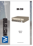
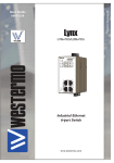
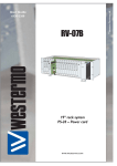
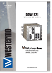
Viper-12
s e r i e s
X1
DC
SRV 1
X2
SRV 2
X3
X4
X5
X9
X6
X10
X7
X11
X8
X12
X1
X5
X9
X6
X10
X7
X11
X8
X12
ON
USB
X2
RSTP
FRNT
X3
CON
DC
X4
12-port Ethernet M12 switch
www.westermo.com
License Information
This device contains public available software which is under the GPL license.
For more information see legal.pdf included with all firmware releases.
This product includes software developed by the OpenSSL Project for use in the
OpenSSL Toolkit. http://www.openssl.org
Legal information
The contents of this document are provided “as is”. Except as required by applicable
law, no warranties of any kind, either express or implied, including, but not limited to,
the implied warranties of merchantability and fitness for a particular purpose, are made
in relation to the accuracy and reliability or contents of this document. Westermo
reserves the right to revise this document or withdraw it at any time without prior
notice.
Under no circumstances shall Westermo be responsible for any loss of data or income
or any special, incidental, and consequential or indirect damages howsoever caused.
More information about Westermo can be found at the following Internet address:
http://www.westermo.com
2
6641-2241
Safety
!
Before installation:
Read this manual completely and gather all information on the unit. Make sure that
you understand it fully. Check that your application does not exceed the safe operating specifications for this unit.
This unit should only be installed by qualified personnel.
This unit should be built-in to an apparatus cabinet, or similar, where access is
restricted to service personnel only. The power supply wiring must be sufficiently
fused, and if necessary it must be possible to disconnect manually from all power
supply. Ensure compliance to national installation regulations. This unit uses convection cooling. Make sure that the unit is installed such as its ambient temperature is
within its specified maximum/minimum temperature.
!
Before mounting, using or removing this unit:
Prevent access to hazardous voltage by disconnecting the unit from all power supply.
Warning! Do not open connected unit. Hazardous voltage may occur within this
unit when connected to power supply.
Before powering-up, a protective earthing conductor must be connected to the
protective earthing terminal and have a cross-sectional area of at least 1.5 mm².
Note that this unit can be connected to two different power sources.
WARNING
When this unit is operated at an ambient temperature above +55°C, the External
Surface of Equipment may exceed Touch Temperature Limit according to EN/IEC/
UL 60950-1.
CAUTION – To reduce the risk of fire, use only No. 26 AWG or larger telecommunication line cord.
Care recommendations
Follow the care recommendations below to maintain full operation of unit and to fulfill
the warranty obligations.
This unit must not be operating with removed covers or lids.
Do not attempt to disassemble the unit. There are not any user serviceable parts inside.
Do not drop, knock or shake the unit. Rough handling above the specification may cause
damage to internal circuit boards.
Do not use harsh chemicals, cleaning solvents or strong detergents to clean the unit.
Do not expose the unit to any kind of liquids (rain, beverages, paint etc), unless all
connectors and the ventilation membrane are sufficiently protected.
Do not use or store the unit in dusty or dirty areas, unless all connectors and the
ventilation membrane are sufficiently protected.
Do not cover or bring mechanical force to the ventilation membrane on the back
of the unit.
If the unit is not working properly, contact the place of purchase, nearest Westermo
distributor office or Westermo Tech support.
Maintenance
No maintenance is required, as long as the unit is used as intended within the specified
conditions.
6641-2241
3
Agency approvals and standards compliance
Type
Approval / Compliance
EMC
EN 61000-6-1, Immunity residential environments
EN 61000-6-2, Immunity industrial environments
EN61000-6-3, Emission standard for residential, commercial and light-industrial
environments
EN 61000-6-4, Emission industrial environments
EN 55022 +A1, Emission IT equipment
EN 55024, Immunity IT equipment
FCC part 15 Class B
EN 50121-4, Railway signaling and telecommunications apparatus
EN 50121-3-2:2006 Railway applications –Rolling stock – apparatus
EN 50155:2007 Railway applications – Electronic equipment used on rolling stock
IEC 62236-4, Railway signaling and telecommunications apparatus
Safety
EN 60950-1, IT equipment
Environmental
EN 61373:1999
Railway applications – Rolling stock equipment. Shock and vibration tests
IEEE 1478:2001
Environmental conditions for transit rail car electronic equipment
EN 50124-1: 2001+A1:2003+A2:2005
Railway applications – Insulation coordination
Fire safety standard CEN 45545-2
FCC Part 15.105 Notice:
4
This equipment has been tested and found to comply with the limits for a
Class B digital device, pursuant to Part 15 of the FCC Rules. These limits
are designed to provide reasonable protection against harmful interference
in a residential installation. This equipment generates, uses and can radiate
radio frequency energy and, if not installed and used in accordance with
the instructions, may cause harmful interference to radio communications.
However, there is no guarantee that interference will not occur in a particular installation. If this equipment does cause harmful interference to radio
or television reception, which can be determined by turning the equipment
off and on, the user is encouraged to try to correct the interference by
one or more of the following measures:
… Reorient or relocate the receiving antenna
… Increase the separation between the equipment and receiver
… Connect the equipment into an outlet on a circuit different from that to
which the receiver is connected
… Consult the dealer or an experienced radio/TV technician for help.
6641-2241
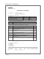
Declaration of Conformity
Westermo Teleindustri AB
Declaration of conformity
The manufacturer
Westermo Teleindustri AB
SE-640 40 Stora Sundby, Sweden
Herewith declares that the product(s)
Type of product
12-port unmanaged Ethernet M12 Switch
Model
Viper-012
Art no
3641-0540
12-port managed Ethernet M12 Switch
Viper-112
3641-0555
12-port managed Ethernet M12 Switch
Viper-212
3641-0560
is in conformity with the following EC directive(s).
No
Short name
2004/108/EC
2006/95/EC
Electromagnetic Compatibility (EMC)
Low voltage (LVD)
References of standards applied for this EC declaration of conformity.
No
EN 50121-3-2
Title
Railway applications - Electromagnetic compatibility -Rolling stock - Apparatus
Issue
2006
EN 50121-4
Railway applications - Electromagnetic compatibility - Emission and immunity of
the signalling and telecommunications apparatus
Information technology equipment - Radio disturbance characteristics - Limits and
methods of measurement
Information technology equipment - Immunity characteristics - Limits and methods
of measurement
2006
EN 55022
EN 55024
EN 61000-6-1
EN 61000-6-2
EN 61000-6-3
EN 61000-6-4
EN 60950-1
Electromagnetic compatibility - Generic standards - Immunity for residential,
commercial and light-industrial environments
Electromagnetic compatibility - Generic standards - Immunity for industrial
environments
Electromagnetic compatibility - Generic standards - Emission standard for
residential, commercial and light-industrial environments
Electromagnetic compatibility - Generic standards - Emission standard for
industrial environments
Information technology equipment - Safety - General requirements
The last two digits of the year in which the CE marking was affixed:
2006
+A1:2007
1998
+A1:2001
+A2:2003
2007
2005
2007
2007
2006
+A11:2009
+A1:2009
+A12:2011
11
Pierre Öberg
Technical Manager
13th December 2011
Postadress/Postal address
Tel.
Telefax
Postgiro
Bankgiro
Org.nr/
Corp. identity number
Registered office
S-640 40 Stora Sundby
Sweden
016-428000
Int+46 16428000
016-428001
Int+46 16428001
52 72 79-4
5671-5550
556361-2604
Eskilstuna
6641-2241
5
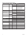
Type tests and environmental conditions
Environmental phenomena
ESD
Basic standard Description
EN 61000-4-2
Enclosure
Fast transients
EN 61000-4-4
Surge
EN 61000-4-5
Power port
Signal ports
Earth port
Power port
Power frequency magnetic field
Pulsed magnetic field
Radiated RF immunity
EN 61000-4-8
EN 61000-4-9
EN 61000-4-3
Ethernet ports
Enclosure
Enclosure
Enclosure
Conducted RF immunity
EN 61000-4-6
Radiated RF emission
Conducted RF emission
EN 55022
FCC Part 15
EN 55022
Dielectric strength
EN 60950-1
Environmental
Temperatures
Humidity
Altitude
Service life
MTBF
Vibration
Shock
Bump
Enclosure
Dimension W x H x D
With connectors
Weight
Degree of protection
Cooling
IEC 60068-2-6
(sine)
IEC 60068-64
(random)
IEC 60068-2-27
IEC 60068-2-27
EN 60950-1
EN 60529
Power port
Ethernet ports
Earth port
Enclosure
Power port
Ethernet ports
Power port to all
other ports
Ethernet ports to all
other ports
Test levels
Contact: ±6 kV
Air: ±8 kV
±5 kV
±5 kV
±1 kV
L-E: ±0.5 kV, 12 Ω, 9 μF, 1.2/50 μs
L-L: ±0.5 kV, 2Ω, 18 μF, 1.2/50 μs
L-E: ±2 kV, 42 Ω, 0.5 μF, 1.2/50 μs
L-L: ±2 kV, 42Ω, 0.5 μF, 1.2/50 μs
L-E: ±8.4 kV, 100 Ω, 0.05/0.1 μs
L-L: ±8.4 kV, 100 Ω, 0.05/0.1 μs
L-E: ±1 kV, 2 Ω L-E: ±2 kV, 42Ω, 0.5 μF
300 A/m; 0, 16.7, 50, 60 Hz
300 A/m
20 V/m @ (80 MHz – 2.7 GHz)
1 kHz sine, 80% AM
10 V, 80% AM, 1 kHz; (0.15 – 80) MHz
10 V, 80% AM, 1 kHz; (0.15 – 80) MHz
10 V, 80% AM, 1 kHz; (0.15 – 80) MHz
Class B
Class B
Class B
Class B
1.5 kV ACrms, 50 Hz, 1 min
1.5 kV ACrms, 50 Hz, 1 min
Operating
Storage and transport
Operating
Storage and transport
Operating
Operating
554,000 h
Non operating long
life simulation
Operating
–40 to +70°C*
–50 to +85°C
5 to 95 % relative humidity
5 to 95 % relative humidity
2 000 m / 70 kPa
15 years
MIL-C217F2, GB, 25°C
7.9 m/s² (RMS) 5 – 150 Hz
Operating
Operating
Zinc
5 g, 30 ms
10 g, 11 ms
Fire enclosure
See "Dimensions" chapter for details
Enclosure
1 m/s² (RMS) 5 – 150 Hz
1.4 kg
IP 65
Convection
* Refer to “Safety” section
6
6641-2241
Description
Viper-12 series is a range of switches consisting of managed and unmanaged versions
developed for rail and industrial applications. To meet the environmental requirements
from rail and harsh industrial applications the switch has rugged M12 Ethernet connectors and full metal housing. The switch fulfills IP 65 degree of protection when all ports
are protected or connected; else IP 40. Our unique FRNT (Fast Recovery of Network
Topology) technology is the fastest protocol on the market to re-configure a network
in the event of any failure of a link or hardware. Real-time properties are implemented
in the switch in order to achieve determinism for real time critical applications. Viper-12
series supports QoS (Quality of Service) with four priority queues and strict priority
scheduling as well as HoL (Head of Line Blocking Prevention). All to assure that the data
network is deterministic.
There are three different models in the Viper-12 series:
3641-0540 Viper-012 unmanaged switch.
3641-0555 Viper-112 managed switch with Layer 2 SW functions.
3641-0560 Viper-212 managed switch with Layer 3 SW functions.
6641-2241
7
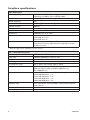
Interface specifications
DC, Power port
Operating voltage
Rated current
Rated frequency
Inrush current, I²t
Startup current*
Polarity
Redundant power input
Isolation to
Connection
Connector size
Rated: 24 to 110 VDC Operating: 24 to 110 VDC ± 30 %
Operating for 100 ms: 24 to 110 VDC ±40%
350 mA @ 24 V and 90 mA @ 110V
DC
1 mA²s @ 24V and 6 mA²s @ 110V
400 mA
Reverse polarity protected
Yes
1500 VAC rms to all other
4 pin male M12 A-coded connector, use Westermo cable
3146-1106 for 1.5 m
3146-1107 for 5 m
M12, recommended cable area 0.5 mm² recommended
(minimum 0.25 mm²), cable dimensions depend on choice
of M12 connector
* External supply current capability for proper start-up
X1 – X12, Ethernet ports
Electrical specification
Data rate
Duplex
Circuit type
Transmission range
Isolation to
Connection
Shielded cable
Conductive housing
Number of ports
8
IEEE std 802.3. 2005 Edition
10 Mbit/s, 100 Mbit/s, manual or auto
Full or half, manual or auto
TNV-1
Up to 150 m with CAT5e cable or better
Other Ethernet ports, 1500 VAC rms
USB and CON or SRV1 and SRV2, 1500 VAC rms
DC, 1500 VAC rms
4-pin M12 D-code, auto MDI/MDI-X, use e g Westermo cable
3146-1100 M12-M12 – 1 m
3146-1101 M12-M12 – 5 m
3146-1103 RJ45-M12 – 1 m
3146-1104 RJ45-M12 – 5 m
Not required, but recommended in severe electromagnetic
environments
Yes
12
6641-2241
USB (Viper-112/212 Managed), USB port
Electrical specification
USB 2.0 host interface
Data rate
Up to 480 Mbit/s (high-speed mode)
Maximum supply current
500 mA
Circuit type
SELV
Isolation to
Ethernet ports, 1500 VAC rms
DC, 1500 VAC rms
No isolation to CON
Connection
5-pin M12 female A-code, use Westermo USB plug 3641-0190
CON (Viper-112/212 Managed), Console port
Electrical specification
RS-232
Data rate
115.2 kbit/s
Data format
8 data bits, no parity, 1 stop bit, no flow control
Circuit type
SELV
Isolation to
Ethernet ports, 1500 VAC rms
DC, 1500 VAC rms
No isolation to USB
Connection
5-pin M12 female B-code, use Westermo cable 1211-2215
SRV1 and SRV2, (Viper-012 Unmanaged)
Service ports that must not be used
Isolation to
Ethernet ports, 1500 VAC rms
DC, 1500 VAC rms
No isolation between SRV1 and SRV2
6641-2241
9
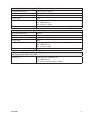
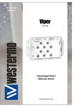
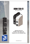
Location of interface ports and LED’s
Ethernet connection TX (X1 – X12)
LED indicators
(for details see page 13)
Position
Signal
Direction
No.1
TD+
In/Out
Description
Transmitted/Received data
No. 2
RX+
In/Out
Transmitted/Received data
No. 3
TX–
In/Out
Transmitted/Received data
No. 4
RD–
In/Out
Transmitted/Received data
Housing
Shield
Enclosure of product (ground)
X1
X5
X9
ON
USB
RSTP
FRNT
X2
X6
X10
X3
X7
X11
X4
X8
X12
CON
DC
Earth
connection
Power connection
4-position
Product marking
Direction
Description
No. 1
+DC1
Input
Supply voltage input DC1
No. 2
+DC2
Input
Supply voltage input DC2
No. 3
-COM
Input
Common
No. 4
-COM
Input
Common
Viper-12 supports redundant power connection.
The positive inputs are +DC1 and +DC2, the negative input
for both supplies are –COM.
10
6641-2241
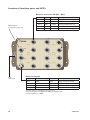
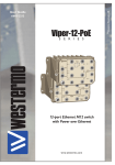
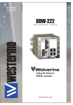
Viper-112/212 Managed
X1
X5
X9
Viper-012 Unmanaged
X1
X5
X9
ON
USB
RSTP
FRNT
X2
X6
X10
SRV 1
X2
X6
X10
X3
X7
X11
SRV 2
X3
X7
X11
X4
X8
X12
X4
X8
X12
CON
DC
DC
Power
Pin number
Signal
No 1
+DC1
No 2
+DC2
No 3
-COM
No 4
-COM
2
1
3
4
USB
Pin number
Signal
No 1
DN
No 2
VBUS
No 3
NC
No 4
DP
No 5
GND
Pin number
Signal
No 1
NC
No 2
TX
CON
No 3
RX
No 4
NC
No 5
GND
6641-2241
11
Connection to console port (Viper-112/212 Managed only)
The console port can be used to connect to the CLI (Command Line Interface).
The following steps needs to be taken
1. Connect the serial diagnostic cable
(use Westermo cable 1211-2215 to the console port).
2. Connect cable to your computer serial port.
3. Use a terminal emulator and connect with correct speed and format (115200, 8N1)
to the assigned port.
For more information about the CLI, see the WeOS management guide.
Connection to USB port (Viper-112/212 Managed only)
The USB port can be used to copy configuration and log files to/from the switch.
The following steps needs to be taken
1. Connect the USB plug (use Westermo USB plug 3641-0190) to the USB port.
2. Access the switch CLI (via console cable or SSH)
3. Use the CLI ''copy'' command to copy files between the USB plug and the switch.
For more information about the CLI, see the WeOS management guide.
12
6641-2241
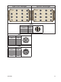
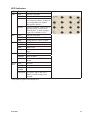
LED Indicators
LED
ON
Status
OFF
GREEN
RED
BLINK
DC
OFF
GREEN
RED
FRNT * OFF
GREEN
RED
BLINK
RSTP*
OFF
GREEN
BLINK
X1 to
X12
OFF
GREEN
GREEN
FLASH
YELLOW
Description
Unit has no power.
All OK, no alarm condition.
Alarm condition, or until unit
has started up. (Alarm conditions
are configurable, see ''WeOS
Management Guide'').
Location indicator ("Here I am!").
Activated when connected to
IPConfig Tool, or when configuring the unit via Web or CLI.
Unit has no power.
Power OK on DC1 and DC1.
Power failure on DC1 or DC2.
FRNT disabled.
FRNT OK.
FRNT Error.
Unit configured as FRNT Focal
Point.
RSTP disabled.
RSTP enabled.
Unit elected as RSTP/STP root
switch.
No Link.
Link established.
Data traffic indication.
X1
X5
X9
ON
USB
RSTP
FRNT
X2
X6
X10
X3
X7
X11
X4
X8
X12
CON
DC
Port alarm and no link. Or if
FRNT or RSTP mode, port is
blocked.
* Only valid for Viper-112 and Viper-212
6641-2241
13
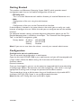
Wall mounting
There are four 6 mm bore holes intended for mounting the unit. The unit can be mounted vertical or horizontal. Use four M6 screws with 12 mm washer on a flat and stable
surface.
X1
X5
X9
ON
USB
RSTP
FRNT
X2
X6
X10
X3
X7
X11
X4
X8
X12
CON
DC
Connection of cables
Recommended tightening torque for the M12 connectors: 0.6 Nm
Removal
Disconnect all cables and unscrew the unit from the wall.
Time For Replacement < 15 minutes
Cooling
This unit uses convection cooling. Avoid obstructing the airflow around the unit. Spacing
is recommended for the use of unit in full operating temperature range and service life.
CEN/TS 45545-2 mounting notes
Two Viper units can be mounted together and as a single interior non-listed group in the
sense of CEN/TS 45545-2 definitions. For multiple units the spacing requirements for
interior non-listed groups must be met.
14
6641-2241
Getting Started
This product runs Westermo Operating System (WeOS) which provides several
management tools that can be used for configuration of the unit.
• IPConfig tool
This is a custom Westermo tool used for discovery of attached Westermo units.
• Web
Configuration of the unit using the web browser.
• CLI
Configuration of the unit via the Command Line Interface.
If the computer is located in the same subnet as the switch you can easily use a web
browser to configure the unit. Within the web you can configure most of the available
functions.
For advanced network settings and more diagnostic information, please use the CLI.
Detailed documentation is available in the chapter ”The Command Line Management
Tool” in the WeOS management guide.
Factory default IP address: 192.168.2.200
Netmask:
255.255.255.0
Gateway:
Disabled
Note! If you are not sure about the subnet – consult your network administrator.
Configuration
Configure the unit via web browser
The unit can easily be configured via a web browser.
Open the link http://192.168.2.200 in your web browser, and you will be prompted with
a Login screen, where the default settings for Username and Password are:
Username: admin
Password: westermo
Once you have logged in, you can use the extensive integrated help function describing
all configuration options. Two common task when configuring a new switch is to assign
appropriate IP settings, and to change the password of the admin account.
The password can be up to 64 characters long, and should consist of printable ASCII
characters (ASCII 33-126); 'Space' is not a valid password character.
Note! Version of IP Config tool must be 10.4.0 or higher.
6641-2241
15
Referring documents
Type
Management Guide
Description
Westermo OS management guide
Document number
6101-3201
Factory default on Viper-112/212
It is possible to set the unit to factory default settings by using two standard Ethernet
M12 cables.
1. Power off the switch and disconnect all Ethernet cables.
2. Connect one Ethernet cable between Ethernet ports X1 and X6, and the other
between Ethernet ports X2 and X5. The ports need to be connected directly by an
Ethernet cable, i.e., not via a hub or switch. Use a straight cable – not a cross-over
cable – when connecting the ports.
3. Power on the unit.
4. Wait for the unit to start up. Control that the ON LED is flashing red.
The ON LED flashing indicates that the unit is now ready to be reset to factory
default.
You now have the choice to go ahead with the factory reset, or to skip factory reset and
boot as normal.
• Go ahead with factory reset: Acknowledge that you wish to conduct the factory reset by unplugging the Ethernet
cables. The ON LED will stop flashing. This initiates the factory reset process*, and after approximately 1 minute the unit
will restart with factory default settings. When the switch has booted up, the ON
LED will show a green light, and is now ready to use.
• Skip the factory reset:
To skip the factory reset process, just wait for approximately 30 seconds
(after the ON LED starts flashing RED) without unplugging the Ethernet cables. The switch will conduct a normal boot with the existing settings.
* Note Do not power off the unit while the factory reset process is in progress.
16
6641-2241
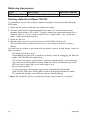
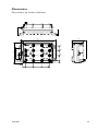
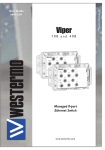
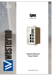
Dimensions
36,7
7,4
Measurements are stated in millimeters.
164
65,2
142
10,9
53,6
73,5
72
48,8
48
56
24
23,3
22,9
100
M5
0
1,5
6,5 (4x)
14
6641-2241
110
111
75
35
1
0
16,1
6,7
17
Westermo Teleindustri AB • SE-640 40 Stora Sundby, Sweden
Phone +46 16 42 80 00 Fax +46 16 42 80 01
E-mail: [email protected]
Westermo Web site: www.westermo.com
United Kingdom
Westermo Data Communications Ltd
Talisman Business Centre • Duncan Road
Park Gate, Southampton • SO31 7GA
Phone: +44(0)1489 580‑585 • Fax.:+44(0)1489 580586
E-Mail: [email protected]
Germany
Westermo Data Communications GmbH
Goethestraße 67, 68753 Waghäusel
Tel.: +49(0)7254-95400-0 • Fax.:+49(0)7254-95400-9
E-Mail: [email protected]
France
Westermo Data Communications S.A.R.L.
9 Chemin de Chilly 91160 CHAMPLAN
Tél : +33 1 69 10 21 00 • Fax : +33 1 69 10 21 01
E-mail : [email protected]
Singapore
Westermo Data Communications Pte Ltd
2 Soon Wing Road #08-05
Soon Wing Industrial Building
Singapore 347893
Phone +65 6743 9801 • Fax +65 6745 0670
E-Mail: [email protected]
North America
Westermo Data Communications
939 N. Plum Grove Road, Suite F
Schaumburg
Chicago
Phone: +1 847 619 6068
Fax: +1 847 619 66 74
E-mail: [email protected]
Taiwan
Westermo Data Communications Co
F2, No. 188, Pao-Chiao Rd.
Shing-Tien City
Taipei 23145
Phone:+886 2 8911 1710
E-mail: [email protected]
Westermo Teleindustri AB have distributors in several countries, contact us for further information.
REV.G 6641-2241 2012-05 Westermo Teleindustri AB, Sweden – A Beijer Electronics Group Company
Sales Units
Sweden
Westermo Data Communications AB
Svalgången 1
SE-724 81 Västerås
Phone: +46 (0)21 548 08 00 • Fax: +46 (0)21 35 18 50
E-Mail: [email protected]