1
VOICECRAFTERTM
3000 Series
Echo Canceling Audio System
operation manual
®
! "#$% &
'(()))*
VOICECRAFTERTM
TABLE OF CONTENTS
TABLE OF CONTENTS
1.
FRONT PANEL FEATURES .............................................................................. 2
2.
REAR PANEL FEATURES ................................................................................ 3
3.
CONNECTOR PIN-OUTS ................................................................................... 4
4.
CONFIGURATION .............................................................................................. 5
5.
USER CONTROL INTERFACE (SOFTWARE) .................................................. 7
6.
INSTALLATION ................................................................................................ 13
7.
CONNECTING EXTERNAL EQUIPMENT ....................................................... 15
8.
TROUBLESHOOTING ...................................................................................... 20
9.
DTMF DIALING & BTV MODE ......................................................................... 24
10.
SPECIFICATIONS ............................................................................................ 26
11.
GENERAL INFORMATION .............................................................................. 28
12.
WARRANTY
13.
WARNING (FCC Compliance)
14.
EQUIPMENT ATTACHMENT LIMITATIONS (Canadian Certification)
1
VOICECRAFTERTM
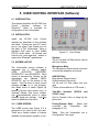
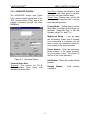
FRONT PANEL FEATURES
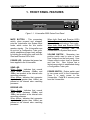
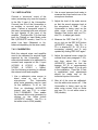
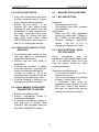
1. FRONT PANEL FEATURES
®
BIAMP SYSTEMS
MUTE
VOICECRAFTERTM 3000
POWER
SEND
VOLUME
POWER
RECEIVE
System Status
Figure 1-1. Voicecrafter 3000 Series Front Panel
When both Send and Receive LED’s
blink Green: Indicates that the
Voicecrafter is performing a Train cycle.
When both Send and Receive LED’s
blink Amber: Indicates that the
Voicecrafter is in System Mute mode.
MUTE BUTTON - This momentary
switch, when pressed and released,
puts the Voicecrafter into System Mute
mode, which mutes the mic and/or
speaker signals. The Voicecrafter can
be put into a Configuration Train cycle,
which establishes proper level settings,
by holding the mute button until both the
Send and Receive LED’s blink.
VOLUME SWITCH - Momentary two
position switch used to raise or lower
User Volume from the front panel. User
Volume affects output level at Speaker
and Line Out. User Volume has a
limited range which is established during
a Configuration Train cycle.
POWER LED - Indicates that power has
been applied to the Voicecrafter.
SEND LED
When Green: Indicates that normal
signal levels (between -30dBm and
-6dBm) are present at the internal echo
canceling processor.
When Amber: Indicates that excessive
signal levels (greater than -6dBm) are
present at the internal echo canceling
processor.
POWER SWITCH - Rocker switch used
to turn power on/off to the Voicecrafter.
Press I to apply power to the
Voicecrafter. Press O to remove power
from the Voicecrafter.
RECEIVE LED
When Green: Indicates that normal
signal levels (between -30dBm and
-6dBm) are present at the internal echo
canceling processor.
When Amber: Indicates that excessive
signal levels (greater than -6dBm) are
present at the internal echo canceling
processor.
2
VOICECRAFTERTM
REAR PANEL FEATURES
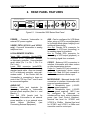
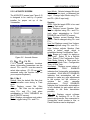
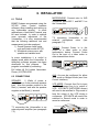
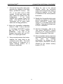
2. REAR PANEL FEATURES
TO TRAIN THIS UNIT, PRESS AND HOLD THE
"MUTE" BUTTON UNTIL TRAINING STARTS.
AUDIO OUT
POWER
2-WIRE PSTN
LOCAL/REMOTE CONTROL
PHONE
AUX
CODEC
IN
SPEAKER
LINE
OUT
OUT
MICROPHONE
OUT
1
2
IN
LINE
Figure 2-1. Voicecrafter 3000 Series Rear Panel
POWER - Connects Voicecrafter to
external DC power supplies.
AUX - Can be configured for VCR Mode
(when using a VCR for record/playback)
or for Bridge Mode (when bridging to an
additional network site).
Aux Out: Female RCA connector for
connection to VCR input (recording), or
for sending signal to a network.
Aux In: Female RCA connector for
connecting to VCR output (playback), or
for receiving signal from a network.
2-WIRE PSTN (VC3010 and VC3011
only) - Connects Voicecrafter to analog
telephone lines.
LOCAL/REMOTE CONTROL
Upper DB9 connector (female/DTE):
Connects to PC, Hand-Held Terminal,
or third-party controller. Uses standard
serial cable (Pin 1 to Pin 1, Pin 2 to
Pin 2, etc.).
Lower DB9 connector (male/DCE):
Connects to external modem, using
standard serial cable. Also can connect
to PC or third-party controller, using nullmodem cable. If the Device that the
Voicecrafter is connecting to does not
control the CTS line, Pins 7 and 8 must
be connected together.
CODEC - Balanced XLR connectors to
interface Voicecrafter with video codecs
or other transmission devices.
Codec In: Female XLR jack connects to
codec or transmission device output.
Codec Out: Male XLR jack connects to
codec or transmission device input.
MICROPHONE - Balanced female XLR
connectors to interface Voicecrafter with
near end sound equipment.
MIC 1: Microphone input (+12VDC
phantom power supplied).
MIC 2: Microphone input (+12VDC
phantom power supplied). MIC 2 can
be
configured
for
balanced
or
unbalanced line input, without phantom
power (see User Control Interface).
Nominal line level for VC3000 and
VC3010 is -35dBm. Nominal line level
for VC3001 and VC3011 is 0dBm and
cannot be used for a mic input.
AUDIO OUT
Speaker: Knife jack terminals for
connecting speakers to Voicecrafter
internal power amplifier (Red is + and
Black is - ).
Line Out: RCA female jack for
connecting Voicecrafter to an external
power amplifier, or to an external mixer
which
utilizes
‘Mix-Minus’
(see
Connecting External Equipment).
3
VOICECRAFTERTM
CONNECTOR PIN-OUTS
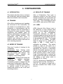
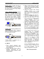
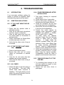
3. CONNECTOR PIN-OUTS
MIC 2 (Line Level)
MIC 1 & MIC 2 (Mic Level)
2
Pin 1 - Chassis Gnd.
or Shield
Pin 2 - Signal (-)
Pin 3 - Signal (+)
1
3
2
1
3
CODEC IN & OUT
Pin 1 - Chassis Gnd.
or Shield
Pin 2 - Signal Ground
2
3
Pin 3 - Signal
High Z (Unbalanced)
600 Ohm (Balanced)
Pin 1 - Chassis Gnd.
or Shield
Pin 2 - Signal (-)
Pin 3 - Signal (+)
600 Ohm (Balanced)
Transformer Isolated
AUXILIARY OUT
AUXILIARY IN
AUDIO LINE OUT
Inner - Signal (+)
Inner - Signal (+)
Inner - Signal (+)
Outer - Signal (-)
Outer - Signal (-)
Outer - Signal (-)
10 k Ohm (Balanced/Unbalanced)
Transformer Isolated
600 Ohm (Balanced/Unbalanced)
Transformer Isolated
LOUDSPEAKER
LOCAL DTE CONTROL
(TOP PORT)
5
600 Ohm (Balanced/Unbalanced)
Transformer Isolated
REMOTE DCE CONTROL
(BOTTOM PORT)
5
1
+
Red - Signal (+)
Black - Signal (-)
9
1
9
6
Pin 1 - +5 VDC
Pin 2 - Tx (From Voicecrafter)
Pin 3 - Rx (To Voicecrafter)
Pin 5 - Ground
2-WIRE PSTN
LINE
6
1
6
Pin 1 - DCD (Not Implemented)
Pin 2 - Rx (To Voicecrafter)
Pin 3 - Tx (From Voicecrafter)
Pin 4 - DTR (From Voicecrafter)
Pin 5 - Ground
Pin 7 - RTS (From Voicecrafter)
Pin 8 - CTS (To Voicecrafter)
2-WIRE PSTN
PHONE
1
6
Pin 1 - PHONE Jack Pin 6
Pin 2 - PHONE Jack Pin 5
Pin 3 - PSTN Tip & PHONE Jack Pin 4
Pin 4 - PSTN Ring & PHONE Jack Pin 3
Pin 5 - PHONE Jack Pin 2
Pin 6 - PHONE Jack Pin 1
1
Pin 1 - LINE Jack Pin 6
Pin 2 - LINE Jack Pin 5
Pin 3 - PSTN Ring & LINE Jack Pin 4
Pin 4 - PSTN Tip & LINE Jack Pin 3
Pin 5 - LINE Jack Pin 2
Pin 6 - LINE Jack Pin 1
Figure 3-1. Connector Pin-Outs
4
VOICECRAFTERTM
CONFIGURATION
4. CONFIGURATION
4.1 INTRODUCTION
4.3 RESULTS OF TRAINING
This chapter describes how to configure
the Voicecrafter, and also defines terms
which are related to the Voicecrafter.
After a Configuration Train cycle is
initiated by means of the User Control
Interface (software), the Voicecrafter will
provide resulting information from the
Train cycle. The Voicecrafter will send
out an AERL value and an ERLE value.
4.2 TRAINING
After all the microphones and speakers
are connected to the Voicecrafter, the
unit needs to be trained before a video
conference or teleconference can be
held. Training is how the Voicecrafter is
configured for proper operation, setting
microphone and speaker gains for
optimum performance, by means of the
User Control Interface software. The
Voicecrafter uses white noise to
establish gain settings as well as to
make an acoustic model of the room for
echo canceling purposes.
4.3.1 AERL
AERL (Acoustic Echo Return Loss) is
the difference in level between what
comes out of the speakers and what is
picked up by the microphones.
Voicecrafter calculates an AERL by
subtracting what is received by the echo
canceller (EC_Si)* from what is sent out
to the speakers (EC_Ri)*. The formula
is (EC_Ri - EC_Si = AERL). An AERL
target is factory set for +10dB, with a
range of 0dB ~ +15dB, which is
adjustable via software. This default
number is used as the basis for a
Configuration Train cycle. This number
represents the amount of attenuation
that the Voicecrafter expects to see, due
to the normal acoustics of the room.
AERL should be within +/-2dB of target.
If the Voicecrafter fails to achieve an
AERL greater than 0dB, the Voicecrafter
will display a train alarm (refer to
paragraph 5.3.4 - Alarm).
(*EC_Si - the amount of signal fed to the
echo canceller from Mic 1 and Mic 2.)
(*EC_Ri - the amount of signal fed to
the echo canceller from Codec In and
Aux In.)
4.3 MODES OF TRAINING
There are 2 modes of training for the
Voicecrafter.
Configuration Train: Training mode
where Voicecrafter sets microphone
gain and speaker gain settings. The
Voicecrafter
also
updates
the
H-register* in this training mode.
Refresh Train: Training mode where the
H-register* is updated (message:
“Voicecrafter
3000
Ready”).
Voicecrafter reverts to settings from the
most recent Configuration Train cycle.
(* H-Register: A memory location where
an acoustic model of the room is
created and stored for use in the echo
canceling process.)
5
VOICECRAFTERTM
CONFIGURATION
Placement of microphones in relation to
speakers is essential for proper training
values. If a microphone is too close to a
speaker, the Voicecrafter may set
microphone or speaker gains to low,
which will affect the AERL. Microphone
default settings also play an important
part in determining AERL and ERLE
values. When connecting a microphone
mixer directly into a Voicecrafter, be
sure that Mic 2 is set for line level input.
The Mic 2 default gain will depend on
the output level of the microphone mixer
(see paragraph 6.3).
4.3.2 ERLE
ERLE
(Echo
Return
Loss
Enhancement) is a measurement of the
Voicecrafters ability to build an echo
canceling model of the room. The
ERLE
is
actually
a
snapshot
measurement taken at the end of a
Configuration Train cycle.
The
Voicecrafter calculates ERLE by taking
what is received by the echo canceller
(EC_Si) and subtracting what is sent
out of the echo canceller (EC_So)*.
The formula is (EC_Si - EC_So =
ERLE). The ERLE should be 8dB or
greater. If the ERLE is 7dB or less, the
Echo canceller will not be able to adapt
quickly to changes in the conference
environment.
(*EC_So - the amount of signal fed out
of the echo canceller to Codec Out and
Aux Out.)
The loopback features, described in
paragraph 5.3.4, are excellent tools for
determining if your microphone gain
and speaker gain settings are correct.
If you talk through a microphone and
get a clear signal during a microphone
loopback, this is a good indication that
the microphone and speaker settings
are correct.
4.4 PROBLEMS WITH TRAINING
AERL and ERLE values can more
easily be achieved by properly adjusting
microphone gain settings, and by
paying
attention
to
appropriate
microphone and speaker alignment.
If the Voicecrafter can’t achieve an
AERL within +/-2dB of target, the target
may need to be raised or lowered
depending on the room. Example: A
large room, which produces excessive
loudspeaker gain and echo after
training, may require the AERL target be
increased. However, a small room,
which produces insufficient loudspeaker
gain, may require the AERL target be
decreased. After adjusting the AERL
target, the Voicecrafter must again be
put through a Configuration Train cycle.
The room should be quiet during any
training cycle. An EC_Si of less than
-35dB is desired for an accurate training
cycle.
This can be measured by
selecting the DSP AVE button on either
the
ACOUSTIC,
NETWORK,
or
DIAGNOSTIC screens. Use F2⇐ or
F3⇒ to display EC_Si.
4.5 MIX-MINUS
When a mixer is connected to both a
Voicecrafter and a local sound
reinforcement system, it is essential that
Voicecrafter output signal never be fed
back to the Voicecrafter input.
Therefore, the mixer must provide an
output to the local sound reinforcement
system, which includes all signals (near
end and far end). In addition, the mixer
must also provide an output to the
Voicecrafter, which includes only local
signals (near end). This is known as a
‘mix-minus’ output.
6
VOICECRAFTERTM
USER CONTROL INTERFACE
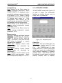
5. USER CONTROL INTERFACE (Software)
5.1 INTRODUCTION
This chapter describes the SC-300 User
Control
Interface
software
for
Windows®, which is provided for
configuration of the Voicecrafter.
5.2 INSTALLATION
Install the SC-300 User Control
Interface as described on the software
disk label. Connect an open PC comm
port to the upper 9-pin female port on
the back of the Voicecrafter, using a
standard 9-pin male to 9-pin female
RS-232 serial cable. All buttons and
controls are ‘point-and-click’, similar to
many other Windows® applications.
Figure 5-1. User Screen
Speaker
The Vol Up and Vol Dwn buttons control
the User Volume.
5.3 SCREEN LAYOUT
The Voicecrafter control software is
separated into 5 different pages:
USER,
ACOUSTIC,
NETWORK,
DIAGNOSTIC, and ADVANCED. Each
screen is accessed by clicking on the
appropriate
tab
(labeled
USER,
ACOUSTIC, etc.) at the bottom of the
screen. Use File menu to save current
software settings or to exit program.
Use Mode menu to select Expert (all
screens), Novice (user screen only), or
Terminal Display (text entry) access.
Use Communications menu to adjust
software serial port settings. Use Help
menu for additional instruction.
Microphone Mute
The Microphone Mute buttons mute and
un-mute the respective mic inputs.
5.3.1 USER SCREEN
Privacy/System Mute - Mutes and
un-mutes
the
Voicecrafter
(see
paragraph 5.3.5).
AUX/VCR Port
Mute selects Record mode.*
UnMute selects Play mode.*
Vol Up and Vol Dwn adjust Aux port
gain.
(*When Voicecrafter is in VCR mode.)
Two-Wire Interface (VC3010 and
VC3011 only)
Use to Connect, Hold, or Hang Up the
phone line.
The USER screen (see Figure 5-1) is
designed to be used by the end user.
There are a limited number of buttons
available for the system operator to use.
Train - Puts the Voicecrafter into a
Configuration Train cycle.
7
VOICECRAFTERTM
USER CONTROL INTERFACE
Input Mode: Selects between Mic level,
Unbalanced line input, or Balanced line
input. Change Input Mode using F2
and F3 (Mic 2 input only).
5.3.2 ACOUSTIC SCREEN
The ACOUSTIC screen (see Figure 5-2)
is designed to be used by a system
installer for proper set up of the
Voicecrafter.
Speaker
AERL: Sets the target AERL to be used
during a Train cycle
Gain: Displays current Speaker Gain.
Can be adjusted using F2 and F3
(only when autoadaption is FULLY
DISABLED via ACOUSTIC screen).
Mute: Displays current Speaker Mute
status. Can be changed using F2 and
F3.
User Vol: Displays current User Volume.
Can be adjusted using F2 and F3.
User Volume adjusts Speaker Gain
within a limited range, which is
established during Configuration Train.
Train: Brings up a menu for starting a
Train cycle. Select F2 for a Refresh
Train. Select F3 for Configuration Train.
Train Mode: Selects a Train mode for
power up. Refresh Train, Configuration
Train, or Skip Train.
AutoAdapt: Displays current status of
autoadaption.
FULLY
ENABLED
indicates that Voicecrafter autoadaption
is enabled. GAIN ADJUST DISABLED
indicates that autoadaption will not
attempt to make any gain adjustments
to the system, but will continue to
optimize
the
echo
canceller
performance.
FULLY DISABLED
indicates that Voicecrafter autoadaption
is fully disabled (no gain adjust and no
changes to the echo cancellation
process).
SW Ver: Displays current software
version. By selecting F2 or F3, the
latest training results, time connected to
Voicecrafter, serial number in Hex, or
Flash Checksum can be displayed.
Figure 5-2. Acoustic Screen
F1, F2, F3, F4, F5,
F1~F5 buttons represents locations
where Voicecrafter parameters can be
stored. F2 and F3 are also used to
select other options. (F1~F5 can not be
accessed using the function keys on
your computer keyboard.)
Mic 1 / Mic 2
Default: Sets the default Mic Gain that
the Voicecrafter uses during a Train
cycle.
Gain: Displays current Mic Gain
settings. Mic Gain can be adjusted
using F2 and F3 (only when
autoadaption is FULLY DISABLED via
the ACOUSTIC screen).
Mute: Displays microphone mute status.
Mute is toggled using F2 and F3.
8
VOICECRAFTERTM
USER CONTROL INTERFACE
Config Memory
Store: Brings up the Store menu for
storing Voicecrafter parameters. When
STORE CONFIG? is displayed, select
appropriate memory location for settings
to be stored (F1~F5). When F1 has a
configuration stored, the unit will recall
F1 settings upon power up.
Only
Configuration Train settings will be
saved (manual adjustments to Mic Gain
and Speaker Gain will not be saved).
Recall: Brings up the Recall menu for
recalling stored configuration presets
(locations F1~F5).
Erase: Brings up the Erase menu for
erasing stored configuration presets
(locations F1~F5).
5.3.3 NETWORK SCREEN
The NETWORK screen (see Figure 5-3)
is used to adjust the Voicecrafter
interface to external devices, such as
Codec, VCR, or phone line.
Measurements
DSP AVE: Displays calculated average
levels from the DSP (EC_So, NLP_So,
Codec In, EC_Si, EC_Ri, VCR IN,
AERL, and ERLE). Each time the DSP
AVE button is pressed, a current
average will be displayed.
SEND Mon: Displays current send
speech
level
as
calculated
by
autoadaption.
RCV Mon: Displays current receive
speech levels as calculated by
autoadaption.
Noise: Displays current status of the
internal white noise generator. Noise
can be turned on/off using F2 or F3.
Figure 5-3. Network Screen
Codec Port
Input Offset: The Input Offset Gain can
be raised or lowered using F2 and
F3.
The CODEC/4-wire #1 Input
Offset defaults to a factory preset gain
of 0dB, and should be compatible with
most external equipment or network
interface levels. Input Offset Gain can
be adjusted in cases where an atypical
external interface level is required.
9
VOICECRAFTERTM
USER CONTROL INTERFACE
These adjustments to the CODEC Input
Gain level are used to compensate for
different audio signal levels from a
Video CODEC or 4-wire network. The
user should follow the audio signal level
recommendations of the video codec
manufacturer or network provider. In
typical networks, this signal level is
approximately 0dBm and will be within
the operational capability of the
Voicecrafter factory preset range. For
example: if the audio signal level at the
“CODEC IN” interface port is +6dBm,
the CODEC Input Gain Offset can be
adjusted to -6dB to compensate for the
high input signal level. Conversely, the
CODEC Output Gain should be
adjusted to +6dB to ensure unity gain.
(*Adj. Range = -12dB to +12dB)
Input Gain: Displays the 4-Wire or
Codec Input Gain.
Gain can be
adjusted by pressing F2 or F3.
Output Gain: Displays the 4-Wire or
Codec Output Gain.
Gain can be
adjusted by pressing F2 or F3.
2-Wire Port (VC3010 and VC3011
only)
Hook: Displays current status of 2-wire
port (On Line or Off Line). The 2-wire
status can be changed by pressing F2
or F3.
Input Gain: Displays current 2-Wire
Input Gain. Gain can be adjusted by
pressing F2 or F3.
DB9M Baud - Allows baud rate of lower
serial port (DB9M) to be changed.
Change baud rate by pressing F2 or
F3.
5.3.4 DIAGNOSTIC SCREEN
The DIAGNOSTIC screen (see Figure
5-4) is for trouble shooting or fine tuning
the Voicecrafter.
Aux Port
Mode: Displays current mode of the Aux
port. Aux port can be configured for
VCR mode or Bridged mode. Bridged
mode allows both Aux In and Aux Out to
be used simultaneously. VCR mode
allows Aux In and Aux Out only to be
used alternately.
This avoids the
problem of feedback which occurs
between the input and output of a VCR.
Input Gain: Displays current Aux Input
Gain. Gain can be adjusted by pressing
F2 or F3.
Output Gain: Displays current Aux
Output Gain. Gain can be adjusted by
pressing F2 or F3.
VCR Mute: Displays current mute status
of Aux In and Aux Out (while in VCR
mode). In Bridged Mode, Voicecrafter
will display “Bridged Mode” on the
screen.
Figure 5-4. Diagnostic Screen
Loopback
Mic/SPKR: Displays the current state of
the microphone loopback.
Pressing
F2 or F3 will cycle through the
various loopback modes available.
They are as follows:
OFF - No mic loopback occurs.
MIC #1 - Mic #1 is looped back to
Speaker output.
10
VOICECRAFTERTM
USER CONTROL INTERFACE
MIC #2 - Mic #2 is looped back to
Speaker output.
MIC #1 & #2 - Mic #1 & Mic #2
looped back to Speaker output.
4-Wire: Displays the current state of the
4-Wire loopback.
Pressing F2 or
F3 will cycle through the various
loopback modes available. They are as
follows:
OFF - No loopback process.
CODEC LOOP - CODEC IN signal is
looped back to CODEC OUT.
AUX/VCR LOOP - Signal from AUX
IN is looped back to AUX OUT (only
when Bridged mode is selected).
CODEC & AUX/VCR LOOP - Both
CODEC LOOP and AUX/VCR LOOP
modes are selected.
Near Thresh: Displays the current NLP
near end noise setting. This setting is
used to optimize the Non-Linear
Processor for the ambient noise
conditions of the room. The value of
this setting can be changed using F2
or F3. The available options are:
00min
01weak
02weak
03weak
04weak
05normal (default)
06strong
07strong
08strong
09strong
10Max
Alarm - Displays current alarm status of
the Voicecrafter. A display of Alarm
0x0000 indicates that no alarm condition
exists. Latch indicates if an alarm has
ever existed. The third line indicates the
results of an EC ASIC test that is
executed when Alarm is pressed. To
clear a Latch, click F3 after Alarm is
selected.
Far Thresh: This function has been
obsoleted.
Echo Canceller
Cancellation: Displays current status of
the echo canceller. The echo canceller
is enabled or disabled using F2 or
F3.
H-Reg: Displays current status of the
H-register. The H-register is enabled or
disabled by using F2 or F3.
Decode Alarm - Displays the meaning
of an alarm that has occurred.
Convergence: Displays current state of
Convergence. Convergence is enabled
or disabled using F2 or F3.
NLP Config
NLP: Displays current status of the NLP
(Non-Linear Processor).
NLP is
enabled or disabled using F2 or F3.
11
VOICECRAFTERTM
USER CONTROL INTERFACE
Hold Time: Displays the amount of time
it takes for the noise gate to activate,
once the room has become silent.
Decay Time: Displays how quickly the
noise gate will suppress noise, once the
room has become silent.
5.3.5 ADVANCED SCREEN
The ADVANCED screen (see Figure
5-5) is used to make adjustments to the
TNG (Transmit Noise Gate), and to the
modem connection through the lower
DB9M port.
Privacy Mode - Defines what is muted
when Mute or System Mute buttons are
activated. Select Mic Only, or Mic and
Speaker, using F2 and F3.
Modem Init String - If you are using
the null-modem (lower) port to connect
your Voicecrafter to a modem, you will
need to enter the initialization string for
your modem in the space provided.
Phone Number - Enter the destination
phone number, in the space provided,
for your modem to dial. (This does not
dial out of the 2-wire interface.)
Figure 5-5. Advanced Screen
Dial Modem - Starts the modem dialing
process.
Transmit Noise Gate
Threshold: This controls the EC_Si
(Echo Canceler Send Input) that
activates the Noise Gate.
Hangup Modem
connection.
12
-
Ends
modem
VOICECRAFTERTM
INSTALLATION
6. INSTALLATION
MICROPHONE: Connect mics to XLR
connectors labels MIC 1 and MIC 2 on
the Voicecrafter.
6.1 TOOLS
BIAMP Systems recommends using the
SC-300
(User
Control
Interface
software) when installing and setting up
any Voicecrafter product.
In some
applications a Hand-Held Terminal may
be used instead. In order to achieve
more accurate adjustment of the
Voicecrafter, it is also recommended
that the following additional test and
measurement tools be employed:
1) Sound Pressure Level meter,
such as Extech model 407750.
2) White/pink noise source, with
speaker and variable level.
TO TRAI N THIS UNIT, PRESS AND HOL D THE
"MUTE" BUTTON UNTIL TRAI NING STARTS.
POWER
2-W IRE
CODEC
AUX
AUDIO OUT
IN
LINE
PSTN
SPEAKER
OUT
OUT
OUT
LINE
MICROPHONE
OUT
LINE
1
OR
2
MIC 1
+
TO TRAIN THIS UNIT, PRES S AND HO LD THE
"MUT E" BUTT ON UNTIL T RA INI NG STA RTS .
POWER
MIC 2
M
I
X
E
R
2-WIRE
AUDIO OUT
CODEC
AUX
IN
LI N E
PSTN
SP EAK ER
OU T
OU T
MICROPHONE
OU T
1
2
IN
LO CAL /REM OT E C ONT R O L
PH O NE
+
LI N E
AUX: Aux can be configured for either
VCR mode or Bridged mode (see User
Control Interface).
VCR MODE: Connect Aux Out to input
of VCR. Connect Aux In to output of
VCR. VCR MUTE (NETWORK screen)
will need to be switched to Play mode to
hear the output of the VCR during a
conference. VCR MUTE will need to be
switched to Record mode in order to
record a conference.
2
IN
LOCA L/REMOTE C ON TROL
PHONE
IN
IN
OUT
CODEC: Connect Codec In to the
output of a video codec or other
transmission device. Connect Codec
Out to the input of a video codec or
other transmission device.
MICROPHONE
1
OUT
**If connecting Voicecrafter to an
external
microphone
mixer
(see
paragraph 7.2).
SPEAKER:
5 Watts of power is
available into a 4 ohm minimum speaker
load. Wire the speaker positive to the
Red (+) terminal, and wire the speaker
negative to the Black (-) terminal.
POWER
CODEC
AUX
LINE
LOCA L/REMOTE CONTROL
PHONE
6.2 CONNECTIONS
TO TRAIN THIS UNIT, PRESS AND HOL D THE
"MUTE" BUTTON UNTIL TRAINING STARTS.
AUDIO OUT
PSTN
SPEAKER
In some installations it is useful to
display levels within the Voicecrafter. A
third-party software program has been
developed for this purpose.
This
program is available by contacting:
Ed Lethert @ Ed Lethert Associates.
Phone: (612) 545-0030
S
P
E
A
K
E
R
2- WIRE
+
**If connecting the Voicecrafter to an
external power amplifier (see paragraph
7.3).
T O TRA IN THI S UNIT , P RES S A ND HOL D THE
"MUT E" B UTTON UNTIL TRAI NING START S .
POWER
2-W IRE
13
LINE
IN
LINE
SP EAKER
LOCAL/REMOTE CONTROL
PHONE
CODEC
AUX
AUDIO OUT
PSTN
+
OUT
OUT
IN
OUT
MICROPHONE
1
2
VOICECRAFTERTM
INSTALLATION
BRIDGE MODE: Connect Aux Out to
the input of the device to be ‘bridged’
into the conference. Connect Aux In to
the output of the device being ‘bridged’
into the conference.
3. Place a sound pressure level meter
(SPLM) at the microphone location.
Adjust noise source level until SPLM
measures 72dB.*
4. Using the SC-300 User Control
Interface software, go to the
ACOUSTIC screen and click on DSP
AVE. Click on F3 until EC_Si is
displayed.
5. Click on AutoAdapt, then click F3
until FULLY DISABLED is displayed.
6. Adjust Mic Gain (Using F2 and
F3) until EC_Si of approximately
-20dB is displayed. EC_Si is a
momentary reading, and is only
updated by clicking DSP AVE again.
7. After the correct EC_Si and mic
gains are established, Click on MIC
Default and click F2 or F3 until
Mic Default is equal to established
Mic Gain. If Configuring Mic 2 input
for an external microphone mixer,
see Connecting External Equipment.
LOCAL / REMOTE CONTROL: Connect
computer to the upper DB9 (female)
jack using a standard RS-232 serial
cable connected to the appropriate
comm port of your computer. Configure
the SC-300 User Control Interface
software for proper comm port settings,
using the pull-down menu labeled
COMMUNICATIONS.
TO TRAIN THIS UNIT, PRESS AND HOLD THE
"MUTE" BUTTON UN TIL TRAINING STARTS.
POWER
2-WI RE
AUDIO OUT
CODEC
AUX
IN
LINE
PSTN
SPEAKER
OUT
OUT
MICROPHONE
OUT
1
2
IN
LOCAL/REMOT E CONTROL
PHONE
+
LINE
2-WIRE PSTN: Connect telephone line
to RJ11 jack labeled LINE. Connect a
telephone handset or ringing device to
RJ11 jack labeled PHONE.
TO TRAIN THIS U NIT, PRESS AND HO LD T HE
"MUT E" BUTTON UNTIL TRAINING STARTS.
POWER
2-WIRE
AUDIO OUT
CODEC
AUX
IN
LINE
PST N
SPE AKE R
O UT
O UT
O UT
(*If an external noise source is not
available,
click
on
AutoAdapt
(ACOUSTIC screen), and use F3
to select FULLY DISABLED. Then,
click on Noise and click F3 to enable
noise. Select Speaker Gain and use
F2 or F3 to adjust for a 72dB
reading on the SPLM at the
microphone location. Complete the
Setup procedure, as described
above. Then, set AutoAdapt back to
FULLY ENABLED.)
MICROPHONE
1
2
IN
LOCAL/REMOTE CONTRO L
PHO NE
LINE
+
**2-Wire PSTN is provided only on
models VC3010 or VC3011.
6.3 SETUP
On the ACOUSTIC Screen, click on
the button labeled TRAIN and click
on F3 when prompted. This will
begin a Configuration Train cycle.
1. Place external white/pink noise
source approximately 6 inches away
from microphone.
2. Enable High pass filter on Mics if
available. (Eliminating the low
frequency signals produces better
training results).
End of setup procedure
14
VOICECRAFTERTM
CONNECTING EXTERNAL EQUIPMENT
7. CONNECTING EXTERNAL EQUIPMENT
7.1 INTRODUCTION
7.2.2 CALIBRATION
This chapter describes the procedure
for installing and configuring external
equipment for use with the Voicecrafter.
The Voicecrafter supports the use of an
external microphone mixer and/or an
external power amplifier. An external
microphone mixer is required when
providing more than two microphones.
An external power amplifier is required
when providing distributed loudspeaker
systems. Both an external mixer and an
external amplifier are required when
sound reinforcement of the local
microphones is desired.
The external mixer needs to be
calibrated for the nominal level expected
at the Mic 2 input of the Voicecrafter
(VC3000 & VC3010 = -35dBm;
VC3001
&
VC3011
=
0dBm).
Use the following procedure to calibrate
the external mixer:
1. Apply power to the Voicecrafter and
the external mixer. If Voicecrafter
should attempt to train, wait for train
cycle to complete before continuing.
2. Use a white/pink noise source to
direct noise at one of the
microphones.
The Voicecrafter
white noise generator may be used
for this calibration. To enable the
internal white noise generator, click
on the Noise button (ACOUSTIC
screen) and use F3⇒ to set white
noise to ENA (enable).
7.2 EXTERNAL MIXER WITHOUT
LOCAL REINFORCEMENT
An external microphone mixer is
required
when
more
than
two
microphones are to be used. Mic 2 of
the Voicecrafter is capable of accepting
a signal from an external microphone
mixer. (If sound reinforcement of local
mics is desired, refer to paragraph 7.4.)
3. Use a sound pressure level meter to
measure the noise level at the
microphone.
7.2.1 INSTALLATION
4. Adjust the level of the noise source
so that the sound pressure level at
the microphone is 72dB.
If the
Voicecrafter is being used as the
white noise source, the noise level
can be adjusted by clicking
AutoAdapt (ACOUSTIC screen) and
using F3⇒ to select FULLY
DISABLED.
Then click on the
Speaker Gain button and use F2⇐
and F3⇒ to adjust gain levels.
The Mic 2 input must be configured for a
line level input. Click on Input Mode
under Mic 2 (ACOUSTIC screen). Use
F3⇒ to select Line Input (Balanced or
Un-balanced depending on mixer used).
The output of the external mixer should
be connected to the Voicecrafter Mic 2
input (+ to pin 3, - to pin 2, and ground
to pin 1) using 2-conductor shielded
cable. Microphones are then connected
to the inputs of the external mixer.
5. Measure the DSP Gain EC_Si. To
do this: click on the DSP AVE button
15
VOICECRAFTERTM
CONNECTING EXTERNAL EQUIPMENT
7.3 EXTERNAL AMPLIFIER WITHOUT
LOCAL REINFORCEMENT
(ACOUSTIC screen). Use F2⇐ or
F3⇒ to display EC_Si. EC_Si is a
momentary reading, and is only
updated by clicking DSP AVE again.
The Voicecrafter has a line level audio
output that is capable of driving external
power amplifiers. This line level output
is provided on a rear panel RCA jack
labeled LINE OUT.
6. Adjust the external mixer output for
nominal level (see paragraph 7.2.2).
Then adjust Mic 2 Gain (ACOUSTIC
screen) so that the average EC_Si is
approximately -20dB. Repeat steps
2~5 for all mics in the installation.
Once Mic 2 Gain is established, level
adjustments should be made only at
the individual inputs of the mixer.
7.3.1 INSTALLATION
Connect LINE OUT to the input of the
external amplifier. Connect the external
amplifier to the loudspeakers that are to
be used.
When more than one
loudspeaker is to be used, they should
be wired in phase (loudspeakers wired
out of phase will cause acoustic dead
zones in the conference room). For
distributed loudspeaker systems (25V,
70V, 100V), the external amplifier will
require proper interface for the constant
voltage system which is to be installed.
**The Voicecrafter internal amplifier is
not capable of interfacing to distributed
speaker systems.
7. After all mics are calibrated, click on
Mic 2 Default Gain and use F2⇐
and F3⇒ to make Mic 2 Gain equal
Mic 2 Default Gain. Turn the white
noise source off. If the Voicecrafter
is being used as the white noise
source, click on Noise and use F3⇒
to set white noise to DIS (disable)
Then set Autoadapt back to FULLY
ENABLED.
8. If an external amplifier is to be
provided, as well as an external
mixer, refer to paragraph 7.3.
TO TRAIN THIS UNIT, PRESS AND HOLD THE
"MUTE" BUT TON UNT IL T RAINING ST ART S.
POWER
2-WIRE
AUDIO OUT
CODEC
AUX
IN
LI NE
PSTN
SPEAKER
OUT
OUT
OUT
MICROPHONE
1
2
IN
LOCAL/ REMOTE CONTROL
PHONE
9. Train the Voicecrafter. Click the
Train button (ACOUSTIC screen)
and click on F3⇒ when prompted, to
begin a Configuration Train cycle.
+
LI NE
Voicecrafter
SPEAKER
OUT
IN
- +
Power Amplifier
10. Once acceptable training responses
have been achieved (see paragraph
4.3), store the resulting configuration
by clicking on the Store button
(ACOUSTIC Screen) followed by the
desired memory location (F1~F5).
2-conductor speaker wire
+
-
+
-
16
S
P
E
A
K
E
R
S
P
E
A
K
E
R
Additional speakers must
be wired "In Phase"
VOICECRAFTERTM
CONNECTING EXTERNAL EQUIPMENT
5. Adjust the gain of the external
amplifier so that a sound pressure
level of 72dB is produced at the
sound pressure level meter.
7.3.2 CALIBRATION
The external amplifier needs to be
calibrated for the output level expected
by the Voicecrafter. Use the following
procedure to calibrate the amplifier:
6. Disable the Voicecrafter white noise
generator by clicking on the Noise
button (ACOUSTIC screen) and
using F3⇒ to set white noise to DIS
(disable). Set AutoAdapt to FULLY
ENABLED.
1. Adjust amplifier for low output level.
Apply power to the Voicecrafter and
the external amplifier. If Voicecrafter
should attempt to train, wait for Train
cycle to complete before continuing.
7. Train the Voicecrafter. Click on the
Train button (ACOUSTIC screen)
and click on F3⇒ when prompted to
perform a Configuration Train cycle.
2. Click on AutoAdapt (ACOUSTIC
screen) and use F3⇒ to select
FULLY DISABLED. Then activate
the
Voicecrafter
white
noise
generator by clicking on the Noise
button (ACOUSTIC screen). Use
F3⇒ to set white noise to ENA
(enable). At this point, white noise
(hiss) should be audible from the
loudspeakers. If not, check amplifier
level, speaker wiring, and power.
(The
Receive
LED
on
the
Voicecrafter will be green when
white noise is being generated.)
8. Once acceptable training responses
have been achieved (see paragraph
4.3), store the resulting configuration
by clicking on the Store button
(ACOUSTIC Screen) followed by the
desired memory location (F1~F5).
7.4 EXTERNAL MIXER AND
AMPLIFIER WITH LOCAL
REINFORCEMENT
3. Adjust the Voicecrafter loudspeaker
volume to -10dB. To do this, click on
Speaker Gain button (ACOUSTIC
screen) and use F2⇐ and F3⇒ to
adjust gain levels.
When a mixer is connected to both a
Voicecrafter and a local sound
reinforcement system, it is essential that
Voicecrafter output signal never be fed
back to the Voicecrafter input.
Therefore, the mixer must provide an
output to the local sound reinforcement
system, which includes all signals (near
end and far end). In addition, the mixer
must also provide an output to the
Voicecrafter, which includes only local
signals (near end). This is known as a
‘mix-minus’ output.
4. Using a sound pressure level meter,
measure the noise level at the
conference room table. The sound
level should be measured at a
typical listening position for a
conference participant.
17
VOICECRAFTERTM
CONNECTING EXTERNAL EQUIPMENT
2. Use a sound pressure level meter to
measure the noise level at one of the
microphone locations.
7.4.1 INSTALLATION
Connect a ‘mix-minus’ output of the
mixer (containing only near end signals)
to the Mic 2 input of the Voicecrafter.
Connect Line Out of the Voicecrafter to
an auxiliary or un-used input of the
mixer. Connect a ‘composite’ output of
the mixer (containing both near end and
far end signals) to the input of the
amplifier. Configure Mic 2 for line level
input by Clicking on Input Mode under
Mic 2 (ACOUSTIC screen). Use F3⇒ to
select Line Input (Balanced or Unbalanced depending on the mixer used).
3. Adjust the level of the noise source
so that the sound pressure level at
the microphone is 72dB.
If the
Voicecrafter is being used as the
white noise source click on the
Speaker Gain button and use F2⇐
and F3⇒ to adjust gain levels.
4. Measure the DSP Gain EC_Si. To
do so, click on the DSP AVE button
(ACOUSTIC screen). Use F2⇐ or
F3⇒ to display EC_Si. EC_Si is a
momentary reading, and is only
updated by clicking DSP AVE again.
7.4.2 CALIBRATION
Both the external mixer and amplifier
need to be calibrated for nominal levels
expected by the Voicecrafter.
The
external mixer needs to be calibrated for
nominal level expected at Mic 2 input
(VC3000 & VC3010 = -35dBm;
VC3001
&
VC3011
=
0dBm).
Use the following procedure to calibrate
the external mixer and amplifier:
5. Adjust the external mixer output for
nominal level (see paragraph 7.4.2),
and then adjust Mic 2 Gain
(ACOUSTIC screen) so that the
average EC_Si is approximately
-20dB. Repeat steps 1~4 for all mics
in the installation. Once Mic 2 Gain
is established, level adjustments
should be made only at the
individual inputs of the mixer.
1. Use a white/pink noise source to
direct noise at one of the
microphones.
The Voicecrafter
white noise generator may be used
for this calibration. To do so, first
Click on AutoAdapt (ACOUSTIC
screen) and use F3⇒ to select
FULLY DISABLED. Then, enable
the internal white noise generator by
clicking on the Noise button
(ACOUSTIC screen). Use F3⇒ to
set white noise to ENA (enable).
6. After all of the mics are calibrated,
turn the white noise source off. If the
Voicecrafter is being used as the
white noise source, click on Noise
and use F3⇒ to set white noise to
DIS (disable).
18
VOICECRAFTERTM
CONNECTING EXTERNAL EQUIPMENT
7. Activate the Voicecrafter white noise
generator by clicking on the Noise
button (ACOUSTIC screen). Use
F3⇒ to set white noise to ENA
(enable). At this point, white noise
(hiss) should be audible from the
loudspeakers.
If not, check
amplifier level, speaker wiring, and
power. (The Receive LED on the
Voicecrafter will be green when
white noise is being generated.)
10. Adjust the level of the external
amplifier and/or the mix-minus
output of the external mixer which is
feeding the amplifier, so that 72dB
is measured at the sound pressure
level meter.
11. Disable the Voicecrafter white noise
generator by clicking on the Noise
button (ACOUSTIC screen) and
using F3⇒ to set white noise to DIS
(disable). Then set AutoAdapt back
to FULLY ENABLED.
8. Adjust the Voicecrafter loudspeaker
volume to -10dB. To do so, first click
on AutoAdapt (ACOUSTIC screen)
and use F3⇒ to select FULLY
DISABLED.
Then, click on the
Speaker Gain button and use F2⇐
and F3⇒ to adjust gain levels.
12. Train the Voicecrafter. Click on the
Train button (ACOUSTIC screen)
and click on F3⇒ when prompted to
begin a Configuration Train cycle
13. Once acceptable training responses
have been achieved (see paragraph
4.3),
store
the
resulting
configuration by clicking on the
Store button (ACOUSTIC Screen)
followed by the desired memory
location (F1~F5).
9. Using a sound pressure level meter,
measure the noise level at the
conference room table. The sound
level should be measured at a
typical listening position for a
conference participant.
19
VOICECRAFTERTM
TROUBLESHOOTING
8. TROUBLESHOOTING
8.1
8.2.4 POOR PERFORMANCE AFTER
INSTALLATION
INTRODUCTION
If you encounter problems getting the
system to perform as expected, these
troubleshooting tips should be helpful.
8.2
1. Train again, listening for improved
performance.
2. Check wiring to/from Voicecrafter.
3. Ensure that proper settings for the
microphones have been selected.
4. Check mic orientation: be sure they
are facing away from loudspeakers.
5. Ensure that mics are located at least
4 feet from the loudspeakers.
6. Consult the codec manual for
nominal codec input/output levels
(VC3000 and VC3010 = -20dBm;
VC3001 and VC3011 = 0dBm).
**If lower levels are required,
decrease Codec Out and Increase
Codec In Offset Gain by equal
amounts.
If higher levels are
required, increase Codec Out, and
decrease Codec Input Offset Gain
by equal amounts (NETWORK
screen). There is a 12dB adjustment
range on codec transmission levels).
7. Verify that loudspeakers and wiring
provide a minimum load of 4 ohms,
when using the internal amplifier.
Loudspeakers should be wired in
phase to avoid acoustic dead zones.
SYMPTONS AND ACTIONS
8.2.1 IF YOU CAN'T HEAR THE FAR
END
1. Check that the speaker cable is
attached correctly.
2. Have the far end check microphone
inputs for proper connections.
3. Have far end ensure that mics are
not muted (either at Vocecrafter or
external mixer).
4. Check Voicecrafter for System Mute
at either near end or far end.
5. Verify that the video codec (if any) is
not muted.
8.2.2 IF THE FAR END CAN'T HEAR
YOU
1. Check all microphone inputs.
2. Ensure that mics are not muted
(either at Voicecrafter or external
mixer).
3. Have the far end verify that their
speakers are properly attached.
4. Verify that the video codec (if any) is
not muted.
8.2.5 THIN VOICE QUALITY AT THE
FAR END
1. Try increasing bass settings on far
end mics (watch for signal or echo
canceling degradation).
2. Position far end mics closer to
participants.
8.2.3 ALL CASES
1. Check the lights on the front panel of
the Voicecrafter. The send LEDs
should flash when someone is
speaking. This light activity can be
used as a general indication that the
Voicecrafter is working.
20
VOICECRAFTERTM
TROUBLESHOOTING
3. If the Voicecrafter is set at moderate
loudspeaker volume levels:
Option 1: Adjust NLP Near End
Noise preset (DIAGNOSTIC screen).
Option 2: Train with mic in bass cut
position.
Option 3: Add acoustic treatment.
4. If high local loudspeaker volume:
Option 1: Increase AERL Target by
2~4dB; Train (ACOUSTIC screen).
Option 2:
Adjust NLP preset
(DIAGNOSTIC screen).
Option 3: Train with mic in bass cut
position.
Option 4: Add acoustic treatment.
3. Consider the possibility of adding
more far end mics, or placing mics
closer to conference participants.
**Lower mic levels, or use of an
automatic mixer, will help to limit the
transmission of added room noise.
4. Consider installing or adding to the
existing room acoustic treatment.
8.2.6 POOR PERFORMANCE IN THE
MORNING
1. Train, or save a configuration into F1
memory location so that the
Voicecrafter will recall a saved
configuration upon power-up.
8.2.10 CLIPPING AT THE FAR END
DURING DOUBLE TALK
8.2.7 PERFORMANCE
DEGRADATION AFTER
CONTINUOUS USE
1. Make sure the far end directional
mics are facing away from the
loudspeaker(s).
2. Reduce far end ambient noise.
3. If high local loudspeaker volume:
Option 1: Increase AERL Target by
2~4dB; Train (ACOUSTIC screen).
Option 2: Adjust NLP preset
(DIAGNOSTIC screen).
Option 3: Train with far end mic in
bass cut position.
Option 4: Add room acoustic
treatment at the far end.
4. If moderate local loudspeaker
volume:
Option 1: Adjust NLP preset
(DIAGNOSTIC screen).
Option 2: Add acoustic treatment.
1. Have the far end keep talking
(without near end speech) so that
the Voicecrafter can converge.
2. Train.
8.2.8 ABRUPT POOR
PERFORMANCE
1. Check microphones to ensure
proper positioning.
2. Continue conference momentarily.
Voicecrafter will attempt to correct
itself during incoming speech (from
the far end).
3. Train again.
8.2.9
ECHO AT THE FAR END
8.2.11 CLIPPING AT THE NEAR END
DURING DOUBLETALK
1. Point any directional mics away from
the loudspeakers.
2. Reduce local ambient noise.
1. Follow the procedure discussed in
paragraph 8.2.10 for the Voicecrafter
at the far end.
21
VOICECRAFTERTM
TROUBLESHOOTING
8.2.12 LOCAL DISTORTION
8.3
REASONS FOR ADJUSTMENT
1. Verify that loudspeakers and wiring
provide a minimum load of 4 ohms,
when using the internal amplifier.
2. Reduce far end noise.
If the
Receive LED turns amber during
distorted far end speech, then the
Voicecrafter is being overdriven by
the codec. Adjust the Codec Input
Gain Offset by clicking the Input
Gain Offset button under Codec
(NETWORK screen), and using F2
and F3 to change gain settings.
8.3.1 MIC GAIN SETTING
Symptoms:
• High ambient room noise.
• Low ambient room noise, moderate
room treatment.
Adjustments:
• Select the Mic Gain adjustment
function by clicking Mic 1 Default or
Mic 2 Default on the User Control
Interface
software
(ACOUSTIC
screen).
Use F2 or F3 to
change gain settings, then Train.
8.2.13 THIN VOICE QUALITY AT THE
NEAR END
8.3.2 MIC EQ SETTINGS - BASS
CUT/FLAT/BOOST
1. Try increasing bass setting on near
end mics (watch for training/echo
cancellation degradation).
2. Position near end mics closer to
participants.
3. Consider the possibility of adding
more near end mics, or placing mics
closer to conference participants.
**Lower mic levels, or use of an
automatic mixer, will help to limit the
transmission of added room noise.
4. Consider installing or adding to the
existing room acoustic treatment.
Some
microphones
have
an
equalization switch allowing bass boost,
flat, or cut settings. When this is the
case the proper setting can affect
overall performance.
Symptoms and Adjustments:
• If far end sound quality is too thin try bass flat or boost.
• If far end sound quality is too muddy
or bassy - try bass flat or cut.
• If Voicecrafter trains poorly as
indicated by echo, distortion, or poor
ERLE (less than 7) after training the bass cut setting may improve
training and overall performance.
8.2.14 HIGH AMBIENT ROOM NOISE
TRANSMITTED TO FAR END
1. Reduce local ambient noise.
2. Position microphones closer to
conference participants.
3. If necessary, increase the number of
near end mics to provide better
coverage, then decrease near end
Mic Gain (DIAGNOSTIC screen).
22
VOICECRAFTERTM
TROUBLESHOOTING
8.3.3 WIRE SEND AND RECEIVE
LEVELS
8.3.4 ACOUSTIC ECHO RETURN
LOSS TARGET (AERL)
Symptom:
• Distortion on the loudspeaker signal
at high volume far end speech.
Adjustment:
• Any codec or CLI with nominal audio
levels greater than -20dB (when
used with models VC3000 or
VC3010) or 0dB (when used with
models VC3001 or VC3011) may
require adjustment of Voicecrafter
Codec levels. To accomodate for a
higher transmission level, Codec
Input Gain Offset is decreased and
Codec Output Gain is increased. To
accomodate for a lower transmission
level, Codec Input Gain Offset is
increased, and Codec Output Gain is
decreased.
The Voicecrafter will train based on a
target AERL setting. The default setting
is 10dB.
Symptoms and Adjustments:
• Large
room
where
excessive
loudspeaker volume, echo, and/or
distortion are present after training increase AERL target, and Train.
• Small, highly reverberant room
where volume is too low - decrease
AERL target, and Train.
**The AERL target is adjusted by
clicking AERL (ACOUSTIC screen),
and using F2 or F3 to change
settings.
23
VOICECRAFTERTM
DTMF DIALING & BTV MODE
9. DTMF DIALING & BTV MODE
9.1 DTMF DIALING
The following tables list the s-Commands and t-Commands that support the
Voicecrafter two-wire dialing feature. The Voicecrafter is capable of dialing the full set of
DTMF digits (0-9, A-D, *, and #). The DTMF digits A, B, C and D are not normally
included on standard telephone sets. These digits are used by some communication
systems for auxiliary signaling. DTMF commands can be initialized through third-party
controllers or by entering the ASCII commands in the dialog box at the top of the SC300 User Control Interface software screen.
Table 9-1. Dial Mode s-Commands
Command
HEX Bytes
ASCII Bytes
Dial ‘1’
0x73 0x63 0x6C
‘scl’
Dial ‘2’
0x73 0x64 0x6C
‘sdl’
Dial ‘3’
0x73 0x65 0x6C
‘sel’
Dial ‘A’
0x73 0x66 0x6C
‘sfl’
Dial ‘4’
0x73 0x63 0x6D
‘scm’
Dial ‘5’
0x73 0x64 0x6D
‘sdm’
Dial ‘6’
0x73 0x65 0x6D
‘sem’
Dial ‘B’
0x73 0x66 0x6D
‘sfm’
Dial ‘7’
0x73 0x63 0x6E
‘scn’
Dial ‘8’
0x73 0x64 0x6E
‘sdn’
Dial ‘9’
0x73 0x65 0x6E
‘sen’
Dial ‘C’
0x73 0x66 0x6E
‘sfn’
Dial ‘*’
0x73 0x63 0x6F
‘sco’
Dial ‘0’
0x73 0x64 0x6F
‘sdo’
Dial ‘#’
0x73 0x65 0x6F
‘seo’
Dial ‘D’
0x73 0x66 0x6F
‘sfo’
Hook Flash
0x73 0x63 0x70
‘scp’
Connect Two Wire
0x73 0x6A 0x6D
‘sjm’
Hold Two Wire
0x73 0x6B 0x6D
‘skm’
Hang Up Two Wire
0x73 0x6C 0x6D
‘slm’
24
VOICECRAFTERTM
DTMF DIALING & BTV MODE
Table 9-2. Dial Mode t-Commands
Description
DTMF Mix
Command
(XX)
Values
(yyyy)
0xEC
0x00
0x01 0xFFFF
DTMF Pause
0xED
0x10 0x0100
DTMF Duration
0xEE
DTMF
Attenuation
0xEF
0x10 0x0100
0xFF00 0xFFFD
Dial Mode
0xF0
0x00
0x01 0xFFFF
Setting this parameter to zero disables the DTMF
Mix feature.
Setting this parameter to a non-zero value enables
the DTMF Mix Feature. Any DTMF tones generated
will be audible in the conference mix.
This parameter controls the length of the pause that
is inserted between sequential DTMF digits during
dialing.
This parameter controls the length of the DTMF
tone generated for each digit dialed.
This parameter controls the signal level of the
DTMF tones that are generated and transmitted to
the Two Wire Interface. The value 0xFFFD sets the
DTMF level to maximum. The value 0xFF00 sets
the DTMF level to the minimum. Each step
between the maximum and minimum is a 6dB
increment.
Setting this parameter to zero sets the Voicecrafter
dialing mode to DTMF dialing.
Setting this parameter to any non-zero value sets
the Voicecrafter dialing mode to Pulse Dialing
mode.
The t-Command string consists of a lower case ‘t’, followed by the command (xx),
followed by a value (yyyy), and then a checksum of the prevoius characters in hex.
Examples: DTMF Mix enable = tEC0001BD; DTMF Mix Disable = tEC0000BC.
9.2 BTV MODE
The following table lists the t-Commands that support the Business Television Mode.
Table 9-3. BTV Mode t-Commands
Description
BTV Mode
Command
(xx)
Values
(yyyy)
0xEA
0x00
0x01
0x02
Function
Setting this parameter to zero disables the BTV Mode
feature.
Setting this parameter to 0x0001 will put the Voicecrafter
into the BTV CENTRAL mode. This will cause the Two
Wire Transmit port to be muted. It will also prevent the
Two Wire Receive audio from being re-transmitted to the
Codec Transmit port.
Setting this parameter to 0x0002 will put the Voicecrafter
into the BTV REMOTE mode. This will prevent the
Codec Receive Audio from being re-transmitted to the
Two Wire Interface.
25
VOICECRAFTERTM
SPECIFICATIONS
10. SPECIFICATIONS
)*+,-.**+ %#'/ 0**+,01**+ %#'
2 3!45! 67-889 67-.. 67-.: 7'
8;+ *<
87)= >
8= >
?0< 5@*< 8@5#
!
"# ! $ %&'
%"'
($ %(
'
($ ($ %(
('
.)* 2 >
1*A@
.-* 2
*< @)< 9 $ 5 #9 $ 5.*< @< (
B3 ( !(
0***
B3 ( !(
0*8*
159 8 E
8 2 B 0***9 .59 8 %
F88' G; % !2 $ $'
2 B 0***9 > ( 3 ( *< 2 B 0*8*9 > ( 3 ( *< B3 ( !(
0**8
B3 ( !(
0*88
) 9 1 : $ %2 0 ; A*< > '
8 > .*< 5-*<
2; 3 "
&$ 3
& 8 & . %& '
& . % '
" & (> &> 3
E
@** $ # 8*; $ # # % #'
5))<
$ 8*; $ # # & . E
% #'
" 4#7 <7
B3 ( !(
0*** C 0*8*
B3 ( !(
0**8 C 0*88
( 3 C B3 ( !(
0*** C 0*8*
B3 ( !(
0**8 C 0*88
"
50)<
*< %?8:< ;'
5.*<
*< %?8:< ;'
B3 ( !(
0**8 C 0*889 & . # $ # >
& 8 & . & 8. B 9 . >7
8*; $ # 9 @** $ # 9 . 25.0. < A %8 (9 8 !('
887.)H > 8*H > 87-)H
171 #7
$ > 3
> 4 3
$ D$
D
TO TRAIN THIS UNIT, PRESS AND HOLD THE
"MUTE" BUTTON UNTIL TRAINING STARTS.
TO TRAIN THIS UNIT, PRESS AND HOLD THE
"MUTE" BUTTON UNTIL TRAINING STARTS.
AUDIO OUT
POWER
AUX
CODEC
IN
SPEAKER
LOCAL/REMOTE CONTROL
LINE
OUT
OUT
MICROPHONE
OUT
1
AUDIO OUT
POWER
2
2-WIRE PSTN
LOCAL/REMOTE CONTROL
PHONE
AUX
CODEC
IN
SPEAKER
IN
LINE
OUT
OUT
MICROPHONE
OUT
1
2
IN
LINE
!"#$
%&
!
'#$
'
26
17
18
Mic 1
49
16
16 bit
A/D
+30dB
600W Balanced
w/ Phantom PWR
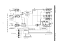
27
Figure 10-3. Voicecrafter 3000 Block Diagram
MIC 2
PreAmp
52
MIC 2 Sel
20
64
25
62
+-
25
AEC
Mic 2
50
Aux Out
16 bit
D/A
+-
25
55
29
22
28
CPU
Signal
Receive
HEC
70
CPU Control Lines
CPU Control Lines
2W
H
PSTN
22
Line Level Output
600 Balanced
37
67
Loopback
Select Mux
VCR Play
10k
Bal
ALaw
D/A
61
16 bit
D/A
Aux In
16 bit
A/D
+-
23
VCR Rec
600
Bal
47
51
25
600W Balanced
w/ Phantom PWR
or
150kW Unbalanced
Line Level Input
Speaker
5 Watt Power Amp
Output
Codec In
600
Bal
16 bit
A/D
62
+30dB
16 bit
A/D
Codec Out
600
Bal
48
25
250mS
Split Band
21 19
16 bit
D/A
ALaw
A/D
Two Wire Option Card
DSP Noise &
Speech Audio
CPU Control Lines
Overload
RS-232 Host Interface
RS-232 Support Interface
Signal
+15Vdc
Send
Overload
Power
Vcc
Flash Memory
31 32 33
RAM
45
SPECIFICATIONS
LED Indicators
VOICECRAFTERTM
MIC 1
PreAmp
VOICECRAFTERTM
GENERAL INFORMATION
11. GENERAL INFORMATION
11.1
Codec - A device which produces a coded
output from an analog input and vice versa.
GLOSSARY OF ECHO
CANCELING TERMS
Acoustic Coupling - Loudspeaker signal
which is picked up by the microphone(s).
Convergence – Echo canceller adaption to
changes in the conference environment.
Acoustically Dead - A conference room
environment with surfaces which reflect
very little sound.
Such environments
contain surfaces such as sound absorbing
panels, curtains, carpeting, etc.
Dead Zone - The area in a conference
room not covered by a microphone,
because it is outside the active pickup
pattern of the microphone.
Disable - To turn off.
Acoustic Echo Return Loss (AERL) - The
amount of signal attenuation which occurs
naturally between the loudspeaker and the
microphone(s).
Ambient Noise - Background noise in the
conference room environment due to air
conditioning/heating equipment, factory
noise, highway noise, etc.
Barrel Effect - A ‘hollow’ sounding signal,
caused by microphones picking up signal
which is reverberating within a room.
Bassy - Pronounced signal strength in the
lower frequency ranges.
Bridge – Interconnection of conference
systems from multiple locations.
Clipping - Signal which is incomplete due to
portions being cut in the process of
transmission.
28
Double Talk - Speech which occurrs
simultaneously
at
more
than
one
conference location at the same time.
EC ASIC - A proprietary, integrated circuit
that performs echo cancellation.
Echo - Signal coupling which occurs
between loudspeakers and microphones
located within the same conference room.
Echo Canceller - An adaptive filter that is
capable of recognizing echo, on a
transmission line, and subtracting it from
the near end speech signal.
Echo Return Loss Enhancement (ERLE) The attenuation applied to the echo signal,
by the adaptive filter of the echo canceller.
Enable – To turn on.
VOICECRAFTERTM
GENERAL INFORMATION
EQ Setting - Refers to the switch, available
on many conference microphones, which
boosts and/or cuts select frequencies.
11.2
ACRONYMS, ABBREVIATIONS
AND SYMBOLS
A
-
Amperes
Far End - A remote or distant site, located
at the opposite end of a conference
transmission line.
AERL -
Acoustic Echo Return
Loss
Gain - Volume.
ASIC -
Application Specific
Integrated Circuit
Near End - The local site on a conference
transmission line.
AUX -
Auxiliary
Non-Linear Processor (NLP) - Device
providing cancellation of residual echo on
the outgoing conference signal.
BW
Bandwidth
CLR -
Clear
Tail Length - The amount of time it takes for
a signal to propagate from the echo
canceller receive out port, and return back
to the send in port, as an echo.
CPU -
Central Processing Unit
DSP -
Digital Signal Processor
DIS
Disable
Transmission Delay - The amount of time
for a signal to travel from a far end site to a
near end site.
-
-
DOC -
Department of Commerce
EC
Echo Canceller
-
EC_Ri
Echo Canceller Receive Input
EC_Si
Echo Canceller Send Input
EC_So
Echo Canceller Send Output
ENA -
Enable
EQ
Equalization
-
ERLE -
Echo Return Loss
Enhancement
FCC -
Federal Communications
Commission
NLP_So Non-Linear
Output
29
Procecessor
Send
VOICECRAFTERTM
GENERAL INFORMATION
HHT -
Hand-Held Terminal
RCV -
Receive
Hz
-
Hertz
SND -
Send
LED
-
Light Emitting Diode
V
Volts
kHz
-
Kilohertz
VDC -
Volts Direct Current
mSec -
Milliseconds
W
-
Watts
NLP
-
Non-Linear Processor
-
Ohms
PC
-
Personal Computer
RAM -
Random Access Memory
30
-
WARRANTY
BIAMP SYSTEMS IS PLEASED TO EXTEND THE FOLLOWING 5-YEAR
LIMITED WARRANTY TO THE ORIGINAL PURCHASER OF THE
PROFESSIONAL SOUND EQUIPMENT DESCRIBED IN THIS MANUAL.
! " #
$# % " " & $' & #
(# )
* ) " & & & )
& ) ) " !
) +
# %
" ! )
+
#
,# % -.// ) 0 1
"& & "& & ! 0 2 #
3# 4 & &
& & & ) ) #
# % 566 7.% 7 7 -7% 66
8.
+6&
7+/7%6&
.
+.79:7%6 /;& 7+6:/7; 6.%
.8%& 6. .8 :& . % /;& 7<: %. ;../=66& . .%5 +.7.+ 6. .8 7
. %# >+% > 6 .-// 5 7&
% /+6 66 .%5 66% %.
: +5 . 7 .%5 .7 7; .:%
.8 : . 8. 7+ .8 %5 ./:+%&
7+6:/7; 66% 8. 7;6;7+ . % +%
66% 7 %. %#
?# %5 = 7% 7 6: .8 66 .%5
= 7% > / . 6/# % > 6 /+6 66 6/
= 7% .8 +57%6% 7/ 8%7
8. %+:6 : .# %5 / %
8. %5 5 7 566 %5 : +5 2 .6
7/ >+6:- / =%5 +% %. 7
/8+%- ./:+%# %5 ;7%& 6.&
/% :%. & 7/ /6 .8 %
7.% :%5. @/ %. ./8 %5 = 7%
. %. A //%.76 = 7% 7/7; .7
%#
++. /7;6& //%.76
%%7% :+5 /6 /- %7%
.
7%%.7 /. 7.% +.7%%:%
= 7% %#
B# 7 #
Thank you for purchasing BIAMP SYSTEMS...
your partner in audio excellence.
Biamp Systems
10074 S.W. Arctic Drive
Beaverton, Oregon 97005 U.S.A.
(503) 641-7287
http://www.biamp.com
585.0147.00
WARNING
FCC COMPLIANCE
WARNING: Changes or modifications to these units not expressly approved by the party
responsible for compliance could void the user's authority to operate the equipment.
NOTE: This equipment has been test and found to comply with the limits for a Class A digital
device, pursuant to Part 15 of the FCC rules. These limits are designed to provide reasonable
protection against harmful interference when the equipment generates, uses and radiates
radio frequency energy and, if not installed and used in accordance with the instruction
manual, may cause harmful interference to radio communications. Operation of this
equipment in a residential area is likely to cause harmful interference in which case the user
will be required to correct the interference at their own expense.
Shield cables must be used with these units to ensure compliance with the Class A FCC
limits.
DOC COMPLIANCE
"This digital apparatus does not exceed the (Class A) limits for radio noise and emissions from
digital apparatus set out in the Radio Interference Regulations of the Canadian Department of
Communications."
"Le pre´sent appareil nume´rique n´emet pas de bruits radioe´lectriques de´passant les limites
applicables aux appareils nume´rques (de la Class A) prescrites dans le Re´glement sur le
brouillage radioe´lectrique e´dicte´ par le ministere des Communications du Canada."
EQUIPMENT ATTACHMENT LIMITATIONS
NOTICE: The Canadian Department of Communications label identifies certified equipment.
This certification means that it meets certain telecommunications, network protective,
operational, and safety requirements. The Department does not guarantee the equipment will
operate to the users satisfaction.
Before installing this equipment, users should ensure that it is permissible to be connected to
the facilities of the local telecommunications company. The equipment must also be installed
using an acceptable method of connection. In some cases, the company's inside wiring
associated with a single line individual service may be extended by means of a certified
connector assembly (telephone extension cord). The customer should be aware that
compliance with the above conditions may not prevent degradation of service in some
situations.
Repairs to certified equipment should be made by an authorized Canadian maintenance
facility designated by the supplier. Any repairs or alterations made by the user to this
equipment, or equipment malfunctions, may give the telecommunications company cause to
request the user to disconnect the equipment.
The user should ensure, for their own protection, that the electrical ground connections of the
power utility, telephone lines and internal metallic water pipe system, if present, are connected
together. This precaution may be particularly important in rural areas.
CAUTION: Users should not attempt to make such connections themselves, but should
contact the appropriate electric inspection authority, or electrician.