1
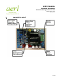
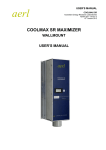
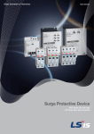
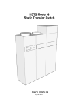
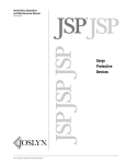
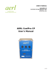
USER'S MANUAL
RACEMAX MAXIMIZER
Australian Energy Research Labs
AER02.004 – ver 4
1 July 2010
AERL RACEMAX MAXIMIZER
User's Manual
1 of 13
USER'S MANUAL
RACEMAX MAXIMIZER
Australian Energy Research Labs
AER02.004 – ver 4
1 July 2010
TABLE OF CONTENTS
1
Overview............................................................................................ 3
2
Maximizer Layout................................................................................3
3
Safety Precautions..............................................................................4
4
Circuit Breakers..................................................................................6
5
5.1
5.2
Installation.........................................................................................7
Mounting............................................................................................................... 7
Connections........................................................................................................... 7
6
6.1
6.2
6.3
Operating Guidelines...........................................................................8
Powering Up the Maximizer...................................................................................8
100% Battery Float Voltage Adjustment................................................................8
Peak Power Tracking Setup...................................................................................9
7
7.1
7.2
7.3
7.4
Troubleshooting................................................................................10
Low Battery Light Often Comes On......................................................................10
Unit Does Not Charge the Battery.......................................................................10
Battery Bank Using Excessive Water (Electrolyte)...............................................10
Maximizer does not boost voltage.......................................................................11
8
Warranty Information........................................................................12
2 of 13
USER'S MANUAL
RACEMAX MAXIMIZER
Australian Energy Research Labs
AER02.004 – ver 4
1 July 2010
1
OVERVIEW
The AERL Race-Trim Mini-Maximizer is a high efficiency, boost only, common
negative peak power point tracker.
It employs a tracking strategy which regulates the PV array voltage to a fixed
percentage of its open circuit voltage. This tracking strategy has been proven to
be highly robust, immune to local extrema, and results in power losses of less
than 0.5% over the whole operating temperature range of a PV array.
The improved power of the new Mini-Maximizer over previous models makes it an
ideal choice for solar car teams looking to get the most out of their PV array.
Additional features include:
• High 98 – 99% operating efficiency.
• Compatible with all types of solar cells and battery arrays.
• Passive cooling & no moving parts results in highly reliable operation to 50°C .
• Output voltage options of 72, 96, 120, 144, 168V.
• Compact and lightweight design, weighing only 750g.
3 of 13
USER'S MANUAL
RACEMAX MAXIMIZER
Australian Energy Research Labs
AER02.004 – ver 4
1 July 2010
2
MAXIMIZER LAYOUT
4 of 13
USER'S MANUAL
RACEMAX MAXIMIZER
Australian Energy Research Labs
AER02.004 – ver 4
1 July 2010
3
SAFETY PRECAUTIONS
WARNING: THE DC VOLTAGE LEVELS AT WHICH THE MAXIMIZER
OPERATES CAN BE POTENTIALLY LETHAL IF HANDLED WITHOUT
ADEQUATE CAUTION.
NEVER TOUCH THE MAXIMIZER AT ANY TIME WHILE IT IS ON. SOME ADJUSTMENTS
CAN ONLY BE MADE TO THE MAXIMIZER WHILE IT IS OPERATING – ENSURE THAT
THESE ARE DONE WITH AN ELECTRICALLY ISOLATED TOOL AND THAT CAUTION IS
USED AT ALL TIMES.
PLEASE NOTE THAT THE “LINK ON/OFF“ CONTROL INPUT DOES NOT ISOLATE THE
INPUTS OR OUTPUTS OF THE MAXIMIZER, IT SIMPLY GENERATES A RESET SIGNAL
THAT DISABLES THE MAXIMIZER. CIRCUITRY ON THE MAXIMIZER BOARD WILL
CONTINUE TO FLOAT AT BATTERY VOLTAGE AND/OR PV VOLTAGE EVEN WITH THE
OFF SWITCH DEPRESSED.
DO NOT EXCEED THE CURRENT AND VOLTAGE RATINGS MARKED ON EVERY
MAXIMIZER, AND LISTED IN THE DATASHEET. TO DO SO, IMMEDIATELY VOIDS THE
WARRANTY.
• In particular the PV Input Open-Circuit Voltage and Current rating must not be
exceeded.
• Always ensure that the Maximizer Off switch on the Piano switch is depressed
before making or breaking any connections.
• Always measure the PV Open-Circuit Voltage and Polarity and Battery Polarity
before closing the circuit-breakers and making the final connection to the
MAXIMIZER.
Note on Maximizer Ratings: To avoid exceeding the maximum short circuit
current listed in the datasheet, care should be taken that the total power rating
of the PV Array does not exceed the battery voltage multiplied by the maximum
short circuit current.
5 of 13
USER'S MANUAL
RACEMAX MAXIMIZER
Australian Energy Research Labs
AER02.004 – ver 4
1 July 2010
4
CIRCUIT BREAKERS
ALWAYS FIT DC RATED INPUT AND OUTPUT PROTECTION CIRCUIT BREAKERS
WITH APPROPRIATE VOLTAGE AND CURRENT RATINGS.
0 – 120V OUTPUT
AERL RaceMax 600B
IN
- +
OUT
+
-
LINK
ON OFF
PV
BAT
MCB
MCB
120 - 180V OUTPUT
AERL RaceMax 600B
IN
- +
OUT
+
-
LINK
ON OFF
BAT
PV
MCB
MCB
Figure 4.1: Maximizer circuit breaker configuration using 60V, 20A 60kA MCBs for different output
voltages.
6 of 13
USER'S MANUAL
RACEMAX MAXIMIZER
Australian Energy Research Labs
AER02.004 – ver 4
1 July 2010
5
INSTALLATION
5.1
MOUNTING
• If the Maximizer is to be mounted in an enclosure, ensure that the cabinet is
large and adequately ventilated. Do not mount the unit anywhere that airflow is
restricted.
• Never mount the unit in a sealed enclosure, it will overheat.
• Power transfer efficiency through the Maximizer will be better the cooler the
unit is kept.
• Do not mount the unit where rain or direct sunlight can reach the unit, or where
moisture condensation can affect the unit.
5.2
CONNECTIONS
• Ensure that the Maximizer is switched OFF by unlinking terminals 6 & 7 on the
main connector.
• Use appropriately rated wire to connect PV input and battery bank output.
Polarity is indicated on the board. Reversing polarity of input or output will
cause damage to the Maximizer.
• Install circuit breakers as described in Section 4.
• Check the polarity of the input and output with a multimeter before switching
on the Maximizer.
• Terminals 6 & 7 (“Link ON”) need to be linked to switch the Maximizer on. It can
be useful to wire a switch in between terminals 6 & 7 to allow the Maximizer
control to be disabled when necessary. Note that switching the Maximizer off by
disconnecting terminals 6 & 7 does not make the Maximizer safe to touch.
7 of 13
USER'S MANUAL
RACEMAX MAXIMIZER
Australian Energy Research Labs
AER02.004 – ver 4
1 July 2010
6
OPERATING GUIDELINES
Ensure that the MAXIMIZER is switched OFF – terminals 6 & 7 are not linked on
the main input connector, before making any electrical connections or closing
any Input and Output Circuit-Breakers.
IMPORTANT: To avoid overloading the Maximizer, pay attention to the warnings
given in Section 3. As mentioned in Section 3, it is important to avoid connecting
the Maximizer to a PV Array if its power rating exceeds the battery bank voltage
multiplied by the maximum short circuit current quoted on the Maximizer
datasheet. To do so will overload the current handling capabilities of the product,
most likely cause damage to the board and void the warranty.
6.1
POWERING UP THE MAXIMIZER
The Racemax Maximizer must have a link placed between terminals 6 & 7 on the
main input connector, where it is marked 'Link for ON' for the control to be
enabled.
It is highly recommended that the Maximizer be connected to the load at all
times when it is enabled. Avoid switching the Maximizer on with the battery
disconnected (i.e. battery circuit breaker open) or disconnecting the battery while
the Maximizer is switched ON.
6.2
100% BATTERY FLOAT VOLTAGE ADJUSTMENT
When connected to a battery pack, the unit is designed to charge to a preset
voltage point and then maintain constant voltage.
The 100% float set point can be adjusted using a combination of the piano
dipswitches to set the appropriate range and the float adjustment trimpot for fine
tuning.
8 of 13
USER'S MANUAL
RACEMAX MAXIMIZER
Australian Energy Research Labs
AER02.004 – ver 4
1 July 2010
Figure 5.1: Charging profile of Mini-Maximizer
If the battery voltage is above the 100% float set point, the 100% full LED will be
on. If the battery voltage is below the 100% float set point, the LED will switch
off. This can be used as feedback to indicate the position of the 100% float set
point, if the Maximizer is connected to a known voltage.
The 100% full LED will work as an indicator of the 100% float set point even if the
Maximizer is disabled.
Adjustment Procedure
• Connect battery pack to output of Maximizer.
• When the battery pack is at the desired top of charge voltage, adjust the piano
dipswitch voltage and the trimpot so that the 100% full LED only just turns on.
The following table shows roughly the range of values that can be set with the
piano dipswitch and the trimpot
9 of 13
USER'S MANUAL
RACEMAX MAXIMIZER
Australian Energy Research Labs
AER02.004 – ver 4
1 July 2010
6.3
PEAK POWER TRACKING SETUP
During normal operation, the Maximizer tracks the peak power point of the PV
array by periodically sampling the open-circuit voltage of the array. It then sets
the array voltage to a percentage (usually between 70 – 85%) of the measured
Voc.
Note: Due to the periodic sampling operation, the Maximizer is disabled to
measure Voc for about 0.066% of its running time.
Adjusting the Voc Percentage (% Voc)
1. With the batteries and the array isolated, connect an ammeter in series
between the battery bank and the Maximizer.
2. Locate VR2, the trimpot just above the header for the control board.
3. Switch the Maximizer on, close the battery and PV array circuit breakers and
measure the current flowing into the batteries. (Note: The batteries will need to
be discharged below the 100% battery float level, and the battery 100% light
should NOT be on during this process).
4. Using a plastic screw driver, sweep the VR2 trimpot through the range to
achieve the maximum current transfer into the batteries. This will set the voltage
at the peak power point for the PV array. Always use caution when making
adjustments to the Maximizer while it is connected to the PV array or the battery
pack.
Note: To achieve best results from the AERL Maximizer, it is recommended that
the Voc Percentage Set-Point be calibrated while the PV Array is experiencing its
most typical operating temperature – more specifically the average of its
expected operating temperature over time.
10 of 13
USER'S MANUAL
RACEMAX MAXIMIZER
Australian Energy Research Labs
AER02.004 – ver 4
1 July 2010
7
TROUBLESHOOTING
7.1
LOW BATTERY LIGHT OFTEN COMES ON
This could indicate that the PV system is underpowered, never reaching a full
108% equalise value. The battery life will be severely compromised in this
situation. The more often the LED comes on, the more power should be added to
the PV array.
Solution: Add more PV modules to the array to increase the power output.
If the array is sufficiently powerful, but the LED is still very often on, check that
the Maximizer is set up for the correct voltage of the battery pack. See section
5.5 for adjusting the battery float voltage. Also check that the Maximizer is
charging the battery by checking the output current on the LCD meter, and if the
Maximizer is not functioning continue to 10.2.
7.2
UNIT DOES NOT CHARGE THE BATTERY
If Temperature Compensation is not being used (default setup) ensure that the
switch marked Temp. Comp. OFF (switch number 9) is pressed down. Not doing
so may cause the unit to behave strangely.
If this is not the cause of the problem, check the following:
• All connections to the Maximizer are secure and screw terminals are done up
tight.
• Check that the Maximizer is enabled using a link between terminals 6 & 7 (Link
ON)
• Check the integrity of the blue circular MOVs. These are surge protectors and
will fail destructively in the event of circuit overload. This could indicate a fault
with the unit and it should be returned for repair.
• Check the integrity of the large crowbar diodes located below the main
inductor winding. These fail destructively if a reverse polarity is applied.
• Check with a multimeter that the input voltage is sufficient to power the
Maximizer. If the input voltage is below the minimum input voltage of the
Maximizer the unit will not power up.
• Note: The minimum input voltage of the Maximizer changes depending
on the nominal voltage of the battery pack in use. The rule of thumb is
Voc > 1.65 x Vnom. Check the datasheet for a graph to show the
minimum input voltage depending on battery pack voltage.
• Email [email protected] with the details of your set up, problem
description and Maximizer model.
11 of 13
USER'S MANUAL
RACEMAX MAXIMIZER
Australian Energy Research Labs
AER02.004 – ver 4
1 July 2010
7.3
BATTERY BANK USING EXCESSIVE WATER (ELECTROLYTE)
The battery bank is lightly loaded compared to the input PV power and rarely
comes off FLOAT voltage.
Solution: Press the 5th Piano Dipswitch marked “Sealed Batts”
FLOAT voltage by 2.5%.
7.4
to drop the
MAXIMIZER DOES NOT BOOST VOLTAGE.
Solution: Check that the Maximizer is enabled using a link between terminals 6 &
7 (Link ON)
12 of 13
USER'S MANUAL
RACEMAX MAXIMIZER
Australian Energy Research Labs
AER02.004 – ver 4
1 July 2010
8
WARRANTY INFORMATION
1.
AERL warrants that the Product will be free from manufacturing defects
for a period of 24 months from the date of dispatch of the products by AERL to
the customer.
2.
The Products technical specifications are contained within the Product
Datasheet. The Product will conform to the technical specifications contained in
the Product Datasheet at the time of dispatch of the Products to the Customer. If
the technical specifications as contained in the Product Datasheet are not met,
AERL will repair, replace the Product, or refund the amount paid by the Customer
in relation to the Product at the Customers option. AERL is under no obligation to
provide assistance or advice to the Customer in relation to the technical
specifications.
3.
The Products must be installed in strict accordance with the Installation
Recommendations listed in this Manual.
4.
In no event will AERL be liable for:
(a)
any loss or damage which the Customer suffers arising from, or
caused or contributed to by, the Customer's negligence or the negligence of
the Customer's agents or servants; and
(b)
special, indirect or consequential loss or damage as a result of a
breach by the Customer of these Standard Terms including, without
limitation, loss of profits or revenue, personal injury, death, property
damage and the costs of any substitute Products which the Customer
obtains.
5.
The Product is not covered for damage occurring due to water, including
but not limited to condensation, moisture damage and other forms of
precipitation.
6.
The Product is not covered for damage occurring due to the Product
being incorrectly installed or installed in a manner not in accordance with the
Installation Recommendations listed in the Product Manual.
7.
The Product is not covered for damage occurring due to failure on the
part of the customer to operate the product in accordance with the technical
specifications as listed in the Product Datasheet.
8.
The Product is not covered for damage occurring due to lightning.
9.
The Product is not covered for situations where it is used in a manner not
specifically outlined in the Product Manual.
10.
If any provision in this document is invalid or unenforceable this
document will remain otherwise in full force apart from such provision, which will
be deemed deleted.
13 of 13