1
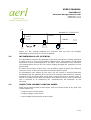
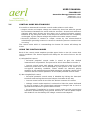
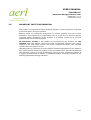
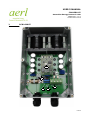
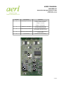
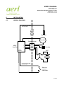
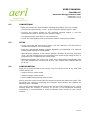
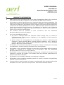
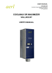
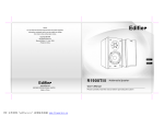
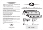
USER'S MANUAL
COOLPRO CP
Australian Energy Research Labs
AER04.002 – ver 1
16 November 2010
AERL CoolPro CP
User's Manual
1 of 14
USER'S MANUAL
COOLPRO CP
Australian Energy Research Labs
AER04.002 – ver 1
16 November 2010
TABLE OF CONTENTS
1
Overview........................................................................................................................3
2
Cathodic Protection Background.....................................................................................4
2.1
Ground Bed Resistance............................................................................................................................4
2.2
Corrosion Potential...................................................................................................................................4
2.3
Reference Cell measurement...................................................................................................................4
2.4
Instantaneous Off Potential......................................................................................................................5
2.5
Protection Current Control Modes............................................................................................................5
2.6
Control Mode Relationships.....................................................................................................................6
2.7
Using the Control Modes..........................................................................................................................6
2.8
Important Safety Information..................................................................................................................7
3
PCB Layout.....................................................................................................................8
4
Circuit Breakers............................................................................................................10
5
Mounting......................................................................................................................10
5.1
Location..................................................................................................................................................10
6
Installation...................................................................................................................11
6.1
Wiring Diagram......................................................................................................................................11
6.2
Connections...........................................................................................................................................12
6.3
Setup......................................................................................................................................................12
6.4
Configuration.........................................................................................................................................12
6.5
Setting the Current Control Mode Setpoint...........................................................................................13
7
Operating Guidelines....................................................................................................13
7.1
Low Battery Cutout................................................................................................................................13
7.2
High Speed Current Interruption............................................................................................................13
7.3
Ref Cell Control mode............................................................................................................................13
8
Warranty Information...................................................................................................14
2 of 14
USER'S MANUAL
COOLPRO CP
Australian Energy Research Labs
AER04.002 – ver 1
16 November 2010
1
OVERVIEW
The AERL CoolPro Cathodic Converter is a robust and integrated cathodic
protection controller which is able to be operated in parallel to protect even the
largest metallic structure.
Its high efficiency makes it perfect for use in solar powered applications. This
efficient power electronics design also minimises component operating
temperature and thermal cycling prolonging the lifetime of the controller even
when operating in high ambient temperatures.
The durable weatherproof enclosure makes the product an excellent choice for
the harsh environments in which cathodic protection is often deployed.
Optional extras such as automatic reference cell control, local or remote
metering and the AERL “Surge Buster” help to protect your investment and get
the most out of your corrosion protection system.
•
High conversion efficiency — 98%
•
Passive cooling – no fans or bulky heat sinks.
•
Durable weatherproof enclosure.
•
Compact and lightweight.
•
Low power consumption.
•
Onboard surge protection with optional supplementary “Surge Buster”
•
High speed ON/OFF control to measure instantaneous off potential
•
Automatic low battery cutout to protect from overdischarge
3 of 14
USER'S MANUAL
COOLPRO CP
Australian Energy Research Labs
AER04.002 – ver 1
16 November 2010
2
CATHODIC PROTECTION BACKGROUND
When a structure corrodes, it is because the environment or another metallic
body (a cathode) becomes involved in a series of chemical reactions with the
structure (the anode). These reactions steal electrons from the metallic bonds
holding the structure together, and corrosion is the result.
Impressed current cathodic protection as employed by the Coolpro CP30 injects
electrical current into the structure, which provides the structure with a surplus
of electrons. This means that electrons can still be provided to the environment
to fuel the cathodic reactions – but the anodic reaction does not occur so metallic
bonds in the structure are safe from degradation.
The protection current is injected using inert metallic anodes and flows through
the ground bed to the structure.
2.1
GROUND BED RESISTANCE
Resistance anywhere in the path between the anode and the structure is a cause
of wasted corrosion protection power and should be minimized. Multiple anodes
are often used to reduce the resistance between the anode and the ground bed.
Additionally, mesh anodes with high surface areas can be used and coke breeze
is used as an interface between the anode and the earth.
2.2
CORROSION POTENTIAL
The corrosion potential of the structure can be thought of as the electrochemical
force driving the anodic reactions in the structure to occur. Corrosion potential
varies depending on the environmental conditions and the presence of other
corrosion inhibiting factors such as a protective coating. Using impressed current
cathodic protection, the aim is to reduce the corrosion potential of the structure
so that the anodic reactions are no longer driven to occur.
Determining the correct level of current to provide to the structure is not trivial.
Providing too little current can mean that the structure is not completely
protected and will corrode. Too much current can lead to other chemical
reactions resulting in effects such as hydrogen embrittlement of the structure
and breakdown of any protective coatings on the pipe.
The corrosion potential of the structure can be determined and accurately
corrected for using a Reference Cell.
2.3
REFERENCE CELL MEASUREMENT
A reference half cell is generally used to survey the corrosion potential in a local
area around the structure to be protected. This determines
the natural
electrochemical corrosion potential which must be cancelled out by impressing
current from the Coolpro Cathodic Converter. From now, all discussions will deal
with a Copper/Copper sulfate half cell which is a commonly employed type.
Impressing current into the structure makes it chemically less anodic, this will be
reflected in its potential measured with respect to the Cu/CuSO4 half cell.
The ideal potential to exist between a Cu/CuSO4 reference cell and a structure is
850mV (with the reference cell more positive).
4 of 14
USER'S MANUAL
COOLPRO CP
Australian Energy Research Labs
AER04.002 – ver 1
16 November 2010
Potential
(E)
Potential of Cu/CuSO4 cell
-850mV
-300mV
-1000mV
Unprotected pipe –
corrodes quickly.
No CP
current
Adding more
CP current
Optimal CP
current – very
little corrosion
Impressed
Current (I)
Too much CP current –
other problems
Figure 2.1 The voltage between the structure and the half cell changes
depending on how much CP current is applied.
2.4
INSTANTANEOUS OFF POTENTIAL
It is desirable to measure the potential of the structure while it is being protected
to make sure it is close to the optimal -850mV level. The problem is that while
protection current is flowing there is an ohmic error introduced in the reference
cell measurement due to the CP current flowing through the resistance of the
ground bed.
To reduce the severity of this error, care should be taken to place the reference
cell much closer to the structure than the anode injection point.
To compensate even further for this error, the CP current is removed and then
instantaneously the potential of the structure is measured. Because the corrosion
potential of the structure takes some time to decay back to its natural state, it
can be accurately measured a few milliseconds after the ohmic error is removed.
This is referred to as measuring the “Instantaneous Off Potential” of the
structure.
2.5
PROTECTION CURRENT CONTROL MODES
There are 3 control modes in the Coolpro, only one can be active at any time. The
control modes are
• Output current control mode
• Output voltage control mode
• Structure/Ref Cell potential control mode
5 of 14
USER'S MANUAL
COOLPRO CP
Australian Energy Research Labs
AER04.002 – ver 1
16 November 2010
2.6
CONTROL MODE RELATIONSHIPS
It is useful to understand how these control modes relate to each other.
• Output current and output voltage are related by ohms law with the ground
bed resistance between the anode and the structure. Ground bed resistance
changes with many factors but the major one is ground moisture content.
However at any two given times, if the setup and environment are completely
unchanged, a given output voltage will produce the same output current.
• Struct/ref potential is related to output current by the electrochemical
relationships governing how much current is needed to prevent corrosion from
occurring.
The control mode which is commanding the lowest CP current will always be
active.
2.7
USING THE CONTROL MODES
Each of the control mode setpoints provide upper limits on the CP current that
can be produced. The lowest setpoint will always be the active limit on the CP
current.
a) Using Ref/Cell control
• Struct/ref potential control mode is tuned to give the desired
instantaneous off potential. The process for this is described in Section 7.
• Current control mode and voltage control mode are used to set the
maximum power that can be delivered by the system in the event of a
non-typical operating condition. These should be selected paying
attention to the estimated ground bed resistance and being careful not to
interfere with the normal operation of Struct/Ref potential control mode.
b) Not using Ref/Cell control
• Struct/ref potential control mode is disabled by linking the Struct/ref
terminals and turning the struct/ref trimpot clockwise all the way.
• Current control mode is set to be the desired constant CP current.
• Voltage control mode setpoint is selected to limit the power delivered
by the CP system if the ground bed resistance changes due to local or
generalized reductions in ground bed moisture.
• For example if regulating in current control mode and the ground bed
resistance doubles during a dry period, because P = I2R the power output
will double if not checked by the voltage control mode setpoint.
6 of 14
USER'S MANUAL
COOLPRO CP
Australian Energy Research Labs
AER04.002 – ver 1
16 November 2010
2.8
IMPORTANT SAFETY INFORMATION
The Coolpro can operate at lethal voltages. Extreme caution should be exercised
at all times when using the product.
Battery packs are extremely destructive in reverse polarity and short circuit
situations. The onboard fuse is provided only as a last line of defence against
continual power dissipation in the product. It is always necessary to connect
appropriately sized circuit breakers.
All electronic circuits in the product or connected to the product are not
isolated from the battery. This means that accidentally shorting the control
module or the LCD meter module can cause a destructive failure. Use extreme
caution when the product is live.
Operating the CP controller at times requires trimpot adjustments to be made to
the control module when the product is live and switched on. This should be done
with extreme caution to avoid accidentally causing a short resulting in failure. It
is highly recommended to obtain a completely plastic trimming screwdriver for
making adjustments during operation.
7 of 14
USER'S MANUAL
COOLPRO CP
Australian Energy Research Labs
AER04.002 – ver 1
16 November 2010
3
PCB LAYOUT
5
4
1
3
2
8 of 14
USER'S MANUAL
COOLPRO CP
Australian Energy Research Labs
AER04.002 – ver 1
16 November 2010
Position
Description
Function
1
Input/Output Terminals
Connect battery and load with
polarity marked on board.
Output + to anode.
Output – to structure.
2
Reference cell inputs
Connect to ref cell and to
structure being protected.
3
Current interrupt terminal
Short terminals together to
immediately interrupt current.
4
LCD meter module header
Connect ribbon cable to LCD
meter module
5
Control board
See below for functionality
10
8
7
9
6
9 of 14
USER'S MANUAL
COOLPRO CP
Australian Energy Research Labs
AER04.002 – ver 1
16 November 2010
4
Position
Description
Function
6
Amps – Output current setpoint
Anticlockwise – more current
7
Volts – Output voltage setpoint
Anticlockwise – more voltage
8
Struct/ref – Ref cell control setpoint
Anticlockwise – more protection
9
Battery voltage selector
Select nominal input voltage for low
battery cutout
10
Low batt reset button
Reset hysteresis on low battery
cutout
CIRCUIT BREAKERS
AERL recommends the use of 6kA, 8kA or 10kA DC rated circuit breakers with an
appropriate voltage rating between the batteries and the Coolpro.
Using an output circuit breaker or fuse is not recommended as large currents can
be shunted by the onboard surge protection circuitry and the “Surge Buster”
during surges. This will cause the output breaker to trip unnessecarily.
5
MOUNTING
5.1
LOCATION
• The Coolpro enclosure is not intended to be mounted where splashing water
or direct sunlight can reach the unit.
• The “Surge Buster” and remote LCD meter module are bare PCBs and should
be protected from moisture and animals.
• Cables should always be routed downwards away from the Coolpro so that
moisture which condenses on the cables does not run back into the product.
• The aluminium cold plate on the back of the enclosure is the source of heat
dissipation for the Coolpro. The Coolpro will run more efficiently and last
longer if the product can be spaced out such that air is allowed to flow past
the aluminium plate.
10 of 14
USER'S MANUAL
COOLPRO CP
Australian Energy Research Labs
AER04.002 – ver 1
16 November 2010
6
INSTALLATION
6.1
WIRING DIAGRAM
Surge side
Safe side
SURGE PROTECTION
ON COOLPRO
Ref Cell
Structure
Ref Struct
-
AERL
CoolPro
+
Surge Buster
OUTPUT
+
-
Link
On/Off
INPUT
Anode
BAT
SURGE PROTECTION
ON COOLPRO
Remote
current
interrupt
11 of 14
USER'S MANUAL
COOLPRO CP
Australian Energy Research Labs
AER04.002 – ver 1
16 November 2010
6.2
CONNECTIONS
• Make all connections with breakers isolating the product from any voltage.
• Connect the input battery + and – to the terminals marked input + and –.
• Connect the output anodes to the terminal marked output + and the
protected structure to the terminal marked output –.
• Use appropriately rated wire for all connections.
• Check the input polarity with a multimeter before closing any breakers.
6.3
SETUP
• If not using the Ref Cell control option, link the reference cell terminals to
disable the reference cell functionality.
• Press the appropriate battery voltage dipswitch corresponding to a nominal
battery/input voltage of 12/24/36/48
• Wind all three trimpots on the control module clockwise all the way until they
click – this will correspond to the setpoints of all control loops being at zero, in
preparation for configuring the control loops.
• When the breakers are closed, the “input alive” LED should immediately light
up. If the trimpots are correctly set to zero, the “output alive” LED should not
be lit yet.
6.4
CONFIGURATION
There are 3 control modes in the Coolpro, only one can be active at any time. The
control modes are
• Output current control mode
• Output voltage control mode
• Structure/Ref Cell potential control mode
At any time the control mode with the lowest set point will always be active. The
set points are raised by adjusting the trimpots anticlockwise and lowered by
adjusting them clockwise.
The control mode setpoints will have to be set using the trimpots on the control
module while the Coolpro is running. To do this, a non-conductive trimming
screwdriver is recommended to avoid accidental short circuits on the control
module.
12 of 14
USER'S MANUAL
COOLPRO CP
Australian Energy Research Labs
AER04.002 – ver 1
16 November 2010
6.5
SETTING THE CURRENT CONTROL MODE SETPOINT
• Ensure that all trimpots are adjusted to zero – follow the steps in Section 6.3.
• Now adjust the voltage trimpot (and S/R trimpot if being used) anti-clockwise
by a few turns to move the setpoints up. No current should flow and the
output alive LED should not come on – because the current control trimpot
should still be set to zero current.
• Now the current control setpoint will be the lowest, so it should be limiting the
output. Slowly adjust the trimpot upwards while measuring the output
current. If the output current stops rising while you are adjusting the trimpot,
one of the other control modes may have taken over and you may need to
adjust it higher to let the current control mode start limiting again.
7
OPERATING GUIDELINES
7.1
LOW BATTERY CUTOUT
CoolPro converters are fitted with an automatic low battery cutout feature to
protect lead acid batteries from over-discharge.
The system will cut out when the battery voltage is below the cut-out voltage,
and will wait until the battery has been recharged to the cut-in voltage before
resuming normal operation.
The battery can be forced to cut-in at any time above the cut-out voltage by
pressing the 'low batt reset' pushbutton.
7.2
Nominal Battery
Voltage
Cut-out
Cut-in
12
11V
13V
24
22V
26V
36
33V
39V
48
44V
52V
HIGH SPEED CURRENT INTERRUPTION
The output of the Coolpro can be reduced to zero very quickly for the purposes of
instantaneous off potential measurement. This is done using the terminals
marked Link Off on the Coolpro. Terminals linked = output disabled.
7.3
REF CELL CONTROL MODE
To calibrate the CP for the correct structure/ref cell corrosion potential, adjust the
S/R trimpot on the control module while measuring the structure/ref cell voltage
with a multimeter (or using the high speed current interruption and measuring
with an oscilloscope) until the desired structure/ref cell voltage is reached. The
reference cell can be controlled over a range of +2500mV to -2500mV.
13 of 14
USER'S MANUAL
COOLPRO CP
Australian Energy Research Labs
AER04.002 – ver 1
16 November 2010
8
WARRANTY INFORMATION
1.
AERL warrants that the Product will be free from manufacturing defects for a period of
24 months from the date of dispatch of the products by AERL to the customer.
2.
The Products technical specifications are contained within the Product Datasheet. The
Product will conform to the technical specifications contained in the Product Datasheet
at the time of dispatch of the Products to the Customer. If the technical specifications as
contained in the Product Datasheet are not met, AERL will repair, replace the Product, or
refund the amount paid by the Customer in relation to the Product at the Customers
option. AERL is under no obligation to provide assistance or advice to the Customer in
relation to the technical specifications.
3.
The Products must be installed in
Recommendations listed in this Manual.
4.
In no event will AERL be liable for:
strict
accordance
with
the
Installation
a) any loss or damage which the Customer suffers arising from, or caused or
contributed to by, the Customer's negligence or the negligence of the Customer's
agents or servants; and
b) special, indirect or consequential loss or damage as a result of a breach by the
Customer of these Standard Terms including, without limitation, loss of profits or
revenue, personal injury, death, property damage and the costs of any substitute
Products which the Customer obtains.
5.
The Product is not covered for damage occurring due to water, including but not limited
to condensation, moisture damage and other forms of precipitation.
6.
The Product is not covered for damage occurring due to the Product being incorrectly
installed or installed in a manner not in accordance with the Installation
Recommendations listed in the Product Manual.
7.
The Product is not covered for damage occurring due to failure on the part of the
customer to operate the product in accordance with the technical specifications as
listed in the Product Datasheet.
8.
The Product is not covered for damage occurring due to lightning.
9.
The Product is not covered for situations where it is used in a manner not specifically
outlined in the Product Manual.
10.
If any provision in this document is invalid or unenforceable this document will remain
otherwise in full force apart from such provision, which will be deemed deleted.
14 of 14