1
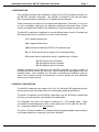
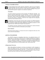
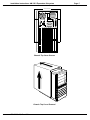
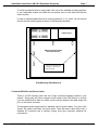
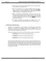
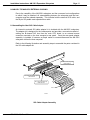
RIGHT. FROM THE START.
RIGHT. FROM THE START.
RIGHT. FROM THE START.
RIGHT. FROM THE START.
RIGHT. FROM THE START.
RIGHT. FROM THE START.
AM-3501
Expansion Subsystem
Installation Instructions
RIGHT. FROM THE START.
RIGHT. FROM THE START.
RIGHT. FROM THE START.
RIGHT. FROM THE START.
RIGHT. FROM THE START.
RIGHT. FROM THE START.
RIGHT. FROM THE START.
PDI-03501-00 A00
© 1995 Alpha Microsystems
REVISIONS INCORPORATED
REVISION
A00
DATE
October 1995
AM-3501 Expansion Subsystem Installation Instructions
To re-order this document, request part number PDI-03501-00.
The information contained in this manual is believed to be accurate and reliable. However, no responsibility
for the accuracy, completeness or use of this information is assumed by Alpha Microsystems.
This document was written and illustrated by Jack Chardi and Dan Twaddell.
This document may contain references to products covered under U.S. Patent Number 4,530,048.
The following are registered trademarks of Alpha Microsystems, Santa Ana, CA 92799:
AMIGOS
AlphaBASIC
AlphaFORTRAN 77
AlphaMATE
AlphaWRITE
VIDEOTRAX
AMOS
AlphaCALC
AlphaLAN
AlphaNET
CASELODE
Alpha Micro
AlphaCOBOL
AlphaLEDGER
AlphaPASCAL
OmniBASIC
AlphaACCOUNTING
AlphaDDE
AlphaMAIL
AlphaRJE
VER-A-TEL
The following are trademarks of Alpha Microsystems, Santa Ana, CA 92799:
AlphaBASIC PLUS
DART
inFront/am
AlphaVUE
ESP
AM-PC
MULTI
All other copyrights and trademarks are the property of their respective holders.
ALPHA MICROSYSTEMS
2722 S. Fairview St.
P.O. Box 25059
Santa Ana, CA 92799
AMTEC
inSight/am
Installation Instructions: AM-3501 Expansion Subsystem
Page i
TABLE OF CONTENTS
1.0 INTRODUCTION . . . . . . . . . . . . . . . . . . . . . . . . . . . . . . . . . . . . . . . . . . . . . . . . 1
2.0 PRODUCT DESCRIPTION . . . . . . . . . . . . . . . . . . . . . . . . . . . . . . . . . . . . . . . . 1
3.0 INSTALLATION PRECAUTIONS . . . . . . . . . . . . . . . . . . . . . . . . . . . . . . . . . . . . 4
4.0 INSTALLATION OVERVIEW . . . . . . . . . . . . . . . . . . . . . . . . . . . . . . . . . . . . . . . 4
4.1 Removing the Top Cover . . . . . . . . . . . . . . . . . . . . . . . . . . . . . . . . . . . . 4
5.0 SCSI PERIPHERAL DEVICES - INSTALLATION AND CABLING . . . . . . . . . . 6
5.1 Internal SCSI Bus and Power Cables . . . . . . . . . . . . . . . . . . . . . . . . . . . 7
6.0 SERIAL I/O BOARDS - INSTALLATION AND CABLING . . . . . . . . . . . . . . . . . 8
6.1 The AM-349 Interface Board . . . . . . . . . . . . . . . . . . . . . . . . . . . . . . . . . 8
6.2 Installing Serial I/O Boards . . . . . . . . . . . . . . . . . . . . . . . . . . . . . . . . . . . 9
7.0 SOFTWARE CONSIDERATIONS . . . . . . . . . . . . . . . . . . . . . . . . . . . . . . . . . . . 10
8.0 AM-3501 TO MAIN CPU EXTERNAL CABLING . . . . . . . . . . . . . . . . . . . . . . . . 11
8.1 Assembling the Host SIO Cable Adapter . . . . . . . . . . . . . . . . . . . . . . . . 11
8.2 Installing the Host SIO Cable Adapter Assembly . . . . . . . . . . . . . . . . . . 12
9.0 ADDITIONAL DOCUMENTATION . . . . . . . . . . . . . . . . . . . . . . . . . . . . . . . . . . . 13
APPENDIX A - PERIPHERAL DEVICE TERMINATORS AND TERMINATION POWER
A.1 SCSI TERMINATION USING EXTERNAL TERMINATOR OPTION . . .
A.2 TERMINATION POWER . . . . . . . . . . . . . . . . . . . . . . . . . . . . . . . . . . . .
A.2.1 SCSI-2 Bus Termination Power Guidelines . . . . . . . . . . . . . .
A.2.2 SASI Bus Termination Power Guidelines . . . . . . . . . . . . . . . .
A.3 ADDITIONAL DOCUMENTATION . . . . . . . . . . . . . . . . . . . . . . . . . . . . .
A-1
A-3
A-3
A-4
A-5
PDI-03501-00, Rev. A00
Installation Instructions: AM-3501 Expansion Subsystem
Page 1
1.0INTRODUCTION
This document describes the installation of both I/O and SCSI peripheral devices into
the AM-3501 expansion subsystem. The AM-3501 is designed to be used with Alpha
Micro computer systems containing an "I/O paddle card bus interface".
These instructions are written for the experienced Alpha Micro Technician, so if you do
not feel comfortable performing the hardware procedures discussed below, please
contact your Alpha Micro Dealer or the Alpha Micro Technical Support Group for help.
The AM-3501 subsystem is designed for several different types of serial I/O boards and
SCSI peripheral devices, including one or more of the following:
1/4" streaming tape drives.
8mm magnetic tape drives.
Both full-high and half-high SCSI 5-1/4" hard disk drives.
3-1/2" SCSI hard disk drives (using 5-1/4" mounting brackets).
The entire family of Alpha Micro serial I/O paddle cards, including:
- AM-355 six port serial I/O boards
- AM-358 eight port serial I/O boards
- AM-359 eight port serial I/O boards
Installing peripheral and I/O devices in the AM-3501 subsystem is simply a matter of
mounting the devices inside the enclosure, and connecting the appropriate power and
interface cables. Once installed, you will need to reference the installation guide for
each of the individual devices for instructions on how to identify the new subsystem
devices to your host computer.
2.0PRODUCT DESCRIPTION
The AM-3501 subsystem can support up to six 5-1/4" half-high SCSI peripheral devices
(as long as the total current draw does not exceed power supply specifications).
The serial I/O expansion on the AM-3501 subsystem uses the "B-Channel" paddle card
bus from your host computer, and standard I/O paddle cards.
The subsystem rear panel will support a maximum of 7 SIO paddle cards. Other
non-serialI/O boards designed to work on the paddle card I/O bus (AM-324, AM-362,
etc...) should be installed in the host computer.
The serial I/O board installation is consistent with the standard paddle cards contained
in the larger Alpha Micro computers, such as the AM-4000.
PDI-03501-00, Rev. A00
Page 2
Installation Instructions: AM-3501 Expansion Subsystem
MC1248
AM-3501 Subsystem
The AM-3501 subsystem looks like your Eagle computer. The dimensions, type of
power supply, and method of installing peripheral devices is exactly the same as the
Eagle computer.
The front panel on the AM-3501 subsystem does not have (or require) an operational
reset button or a digital display. The front panel does have a "power on" status light,
which remains lit whenever the power is on.
You can mix combinations of AM-355, AM-358, and AM-359 I/O boards on the paddle
card bus, subject to the following addressing limitations:
PDI-03501-00, Rev. A00
Installation Instructions: AM-3501 Expansion Subsystem
I/O
ADDRESS
AM355
OCTAL
PORT
NUMBER
F400
0
0
--
1
1
F420
2
2
--
3
3
F440
4
4
--
5
5
F460
6
6
--
7
7
F480
10
10
--
11
11
F4A0
12
12
--
13
13
F4C0
14
14
--
15
15
F4E0
16
16
--
17
17
F500
20
20
AM358
SIO
OCTAL
SELECT
PORT
NUMBERS
NUMBER
--
21
21
F520
22
22
--
23
23
F540
24
24
--
25
25
F560
26
26
--
27
27
F580
30
30
--
31
31
F5A0
32
32
--
33
33
F5C0
34
34
--
35
35
F5E0
--
36
--
--
37
Page 3
AM-359 SIO SELECT
NUMBERS AND
CORRESPONDING
OCTAL PORT
NUMBERS
0
SIO Select #0
1
SIO Select #1
2
SIO Select #2
3
SIO Select #3
4
SIO Select #4
5
SIO Select #5
6
SIO Select #6
7
8
9
10
11
Ports 0 - 7
Ports 10 - 17
Ports 20 -27
Ports 30 - 37
Ports 40 - 47
Ports 50 - 57
Ports 60 - 67
SIO Select #7
Ports 70 - 77
SIO Select #8
Ports 100 - 107
SIO Select #9
Ports 110 - 117
SIO Select #10
Ports 120 - 127
SIO Select #11
Ports 130 - 137
SIO Select #12
12
Ports 140 - 147
13
Ports 150 - 157
14
Ports 160 - 167
15
Ports 170 - 177
SIO Select #13
SIO Select #14
SIO Select #15
B-Channel Serial I/O Addresses
PDI-03501-00, Rev. A00
Page 4
Installation Instructions: AM-3501 Expansion Subsystem
3.0INSTALLATION PRECAUTIONS
To avoid damaging static sensitive electronic components, make sure you are properly
grounded and using a work area suitable for working on electronic equipment. Although
it doesn’t seem like much, that tiny bolt of static electricity discharged through your
finger tips has the power to degrade or ruin electronic components.
Termination:
Two SCSI connectors are present on the rear panel of the AM-3501 subsystem. One
connector should be cabled back to the host computer. The other connector should
have an external SCSI terminator installed, or be connected to yet another external
SCSI device. Make sure that each physicalend of the SCSI bus is properly terminated.
All other SCSI devices in between, in both the host computer and the subsystem,
should have their terminators removed.
See Appendix A at the end of this document which includes more detailed information
about terminating SCSI peripherals and supplying termination power to the SCSI bus.
This information includes the standard Alpha Micro termination procedure for SCSI
peripherals used in AMOS based computers and subsystems.
The installation instructions pertaining to each SCSI peripheral also contains information
on how to configure terminators and termination power jumpers.
Device Address:
SCSI devices daisy-chained to a common bus must be configured so that none of the
devices share the same address.
4.0INSTALLATION OVERVIEW
Your AM-3501 subsystem is assembled at the factory. Any peripheral devices or I/O
paddle cards you order with your AM-3501 will be installed and tested prior to shipment.
However, once you start using your subsystem, you may decide to add extra peripheral
devices or additional I/O boards. The instructions in the following sections describe the
procedure for opening the subsystem, followed by information for installing I/O boards
and SCSI peripheral devices (including magnetic tape, and hard disk drives).
4.1Removing the Top Cover
When adding additional equipment or servicing your subsystem, it will be necessary to
remove the chassis top cover. The top cover is held in place with four phillips-head
screws located along the computer’s rear panel. To remove the top cover, remove all
four screws from the locations indicated in the following illustration. Once the screws
have been removed, the top cover can be slid back and removed.
PDI-03501-00, Rev. A00
Installation Instructions: AM-3501 Expansion Subsystem
Page 5
TOP COVER SCREWS
0
SCSI
1
PRINT PORT 3
115
PRINT PORT 2
PRINT PORT 1
PRINT PORT 0
A
B
C
D
E
F
G
SIO EXPANSION BUS
MC1246
Chassis Top Cover Screws
MC1250
Chassis Top Cover Removal
PDI-03501-00, Rev. A00
Page 6
Installation Instructions: AM-3501 Expansion Subsystem
5.0SCSI PERIPHERAL DEVICES - INSTALLATION AND CABLING
Your subsystem cabinet can physically hold six half-height 5-1/4" peripherals, or three
full-height 5-1/4" peripherals. Filler panels in the subsystem front panel can be removed
to allow access to some of these peripherals. If you have six half-height peripherals,
four of them can be accessed through the front panel; if you have three full-height
peripherals, two of them can be accessed through the front panel.
3-1/2" hard disk drives which are mounted in 5-1/4" mounting brackets, are also
compatible with your subsystem.
The next figure shows all six peripheral device mounting positions in the Eagle
subsystem chassis. For detailed configuration instructions on a particular device, see
the installation instructions for that device.
To install peripherals in mounting
positions 3, 4, 5, and 6, you must
remove the side mounting plate.
The top two mounting positions
can be accessed from either side
of the chassis without having to
remove the side mounting plate.
1
POWER SUPPLY
2
3
4
5
6
NOTE:
All six peripheral mounting positions will
accommodate 3-1/2" devices. However,
before you can mount a 3-1/2" device in the
chassis, the 3-1/2" device must first be
installed in a 5-1/4" mounting bracket.
MC1247
Peripheral Device Mounting Positions
PDI-03501-00, Rev. A00
Installation Instructions: AM-3501 Expansion Subsystem
Page 7
To install a peripheral device, simply slide it into one of the available mounting positions
in your subsystem chassis and install the four screws (two on each side) that hold the
device in place.
In order to install peripheral devices in mounting positions 3, 4, 5, and 6, you will need to
remove the side mounting plate as shown in the following illustration.
1
POWER SUPPLY
2
3
4
5
MAIN ELECTRONICS BOARD
MOUNTING BRACKET
6
To remove the board mounting
assembly, you must remove
these two screws.
MC1158
Side Mounting Plate Removal
5.1Internal SCSI Bus and Power Cables
There is a SCSI interface cable with four 50-pin connectors already installed in your
chassis. Simply plug the 50-pin connector into the back of the SCSI device, or devices
if you are installing more than one. Make sure the colored stripe on the cable aligns with
pin-1 on the device connector.
The subsystem power supply has four standard 4-pin DC power cables. Plug one of the
"keyed" DC power connectors into each device. Note that some cables have both a
standard DC connector and a minature (floppy drive type) connector attached for
convenience.
PDI-03501-00, Rev. A00
Page 8
Installation Instructions: AM-3501 Expansion Subsystem
6.0SERIAL I/O BOARDS - INSTALLATION AND CABLING
The following sections describe how to install serial I/O boards into your AM-3501
subsystem. Depending on board types, you can install up to 7 serial I/O paddle cards
into the subsystem. As previously noted, the B-channel subsystem expansion bus
supports onlyserial I/O paddle cards.
The maximum number of expansion serial I/O boards is determined by two factors: The
number of B-channel I/O addresses consumed by each board, and the physical number
of available rear panel mounting slots. Each AM-358 board consumes (4) I/O
addresses; each AM-355 board consumes (3) I/O addresses; and each AM-359 board
consumes only (1) I/O address.
Referring to the previous B-Channel I/O Address chart you can see that there are only
(16) SIO Board Select Numbers available (0-15), and each board select number
corresponds to a starting I/O address. So, if you are installing onlyAM-358 boards, the
maximum number you can install is four (using SIO Selects 0, 4, 8, and 12). If you are
installing onlyAM-355 boards, the maximum number you can install is five (using SIO
Selects 0, 3, 6, 9, and 12). If you are installing onlyAM-359 boards, the maximum
number you can install is seven (using SIO Selects 0-6) due to the physical number of
mounting slots on the AM-3501 rear panel.
When mixing the various types of I/O boards on the same I/O bus, you must set
the I/O select jumpers on each board based on the number of I/O addresses
consumed by each of the preceeding I/O boards! For more detailed information
refer to the applicable Installation Instructions for each board type.
6.1The AM-349 Interface Board
The AM-349 board, shown in the following illustration, serves several purposes; it has
internal and external 60-pin connectors for linking the serial I/O boards to the rear panel
of the AM-3501 subsystem;it provides power to the serial I/O boards;and it has an on
board load resistor to ensure the power supply always has an adequate load.
The AM-349 is factory installed in the subsystem. The cabling that connects the
AM-349’s external60-pin J3 connector to the rear panel, and the cables supplying
power to the board, are also factory installed. The only connection you will have to
make is plugging in the daisy-chain cable from the serial I/O boards, to the internalJ4
connector on the AM-349 board.
1
EXTERNAL 2
J3
INTERNAL 2
J4
1
MAC510
LOAD RESISTOR
AM-349 Interface Board
POWER CONNECTOR
PDI-03501-00, Rev. A00
Installation Instructions: AM-3501 Expansion Subsystem
Page 9
6.2Installing Serial I/O Boards
All serial I/O paddle cards have factory installed mounting brackets. The following
instructions explain how to install the paddle cards in the AM-3501 subsystem:
1.The serial boards attach directly inside rear panel and are held in place
with three screws. To install a serial I/O board, you must first remove the
filler panel covering the slot where you wish to install the board.
2.The first board should be installed in the 2nd from left or "A" slot, as shown
in the illustration.
0
SCSI
1
PRINT PORT 3
115
PRINT PORT 2
PRINT PORT 1
PRINT PORT 0
A
B
C
D
E
F
G
SIO EXPANSION BUS
FILLER PLATE/SIO
BOARD MOUNTING
SCREWS
MC1249
SIO Paddle Card Mounting Screws
3.If mixing different types of SIO boards, you should first group them
together by type, then set the addressing jumpers in accordance with the
applicable set of installation instructions.
Remember, the three types of I/O boards consume different amounts of
addressing space allocated to the I/O expansion bus. Therefore, as a
general rule you should address and install all the I/O boards which
consume the mostaddress space first, then install all the I/O boards
which consume the next-most address space, etc.
PDI-03501-00, Rev. A00
Page 10
Installation Instructions: AM-3501 Expansion Subsystem
4.You must remove the termination resistor packs from all I/O boards except
the last board on the expansion cable.
5.There is a 60-pin cable in your product installation kit that has seven
60-pin connectors. Start by plugging the cable into the INTERNAL
(J4)connector on the AM-349 board. Make sure the colored stripe on the
cable aligns with pin-1 on the AM-349’s J4 connector.
6.Starting with the first I/O paddle board, connect the cable to each
successive board attached to the rear panel, leaving any unused cable
connectors hanging loose at the end of the cable. Do not twist the cable!
The colored stripe on the cable must align with pin-1 on each of the I/O
paddle board connectors.
7.For additional information on termination and cabling, refer to the
corresponding product installation guide for the various I/O board types.
7.0SOFTWARE CONSIDERATIONS
Information on creating drivers for SCSI peripheral devices supported by the AM-3501
subsystem is contained in the installation guide for each peripheral device. The
information includes termination, addressing, creating software drivers, and adding the
devices to the system initialization command file.
There are three special "B-channel" serial I/O software drivers used for the subsystem:
1. AM355B.IDV is the driver that supports AM-355 boards.
2. AM358B.IDV is the driver that supports AM-358 boards.
3. AM359B.IDV is the driver that supports AM-359 boards.
Each of the above software drivers is unique, and must be used to access the ports on
the corresponding SIO expansion board. When mixing different board types on the
same SIO bus be sure to calculate the correct board select address and octal port
numbering based upon the operational parameters of each preceedingSIO paddle
board on the bus. Refer to the installation instructions for each type of SIO board for
more detailed information.
PDI-03501-00, Rev. A00
Installation Instructions: AM-3501 Expansion Subsystem
Page 11
8.0AM-3501 TO MAIN CPU EXTERNAL CABLING
Due to the versatility of the AM-3501 subsystem and the numerous host configurations
to which it may be attached, all externalcabling between the subsystem and the host
computer must be ordered separately. This includes both the external SCSI cable, and
the 60-pin SIO paddle card expansion bus cable.
8.1Assembling the Host SIO Cable Adapter
An internal to external SIO cable adapter kit is included with the AM-3501 subsystem.
The adapter kit is designed for the hostcomputer and provides a convenient method of
cabling the B-channel SIO bus from the main CPU board, to an external access
connector mounted on the host computer’s rear panel. Once the rear panel adapter
assembly is installed, it becomes a simple matter to connect/disconnect the AM-3501
subsystem to/from the host computer!
Refer to the following illustration and assembly steps to assemble the parts contained in
the SIO cable adapter kit:
Rear Panel Mounting Plate
DWF-20129-20
Connector Mounting Receptacle
CNA-00079-10
60-pin SIO Cable Assembly
DWB-10291-00
Pin-1
MC1251
SIO Cable Adapter Assembly
PDI-03501-00, Rev. A00
U-
CP
To
SIO
io
ns
pa
Ex
l
ne
an
h
nC
Page 12
Installation Instructions: AM-3501 Expansion Subsystem
1.Remove the rear panel mounting plate (DWF-20129-20) and the connector
mounting receptacle (CNA-00079-10) from the shipping kit.
Be sure to use the metricscrews provided with the connector! If you force
a standard-thread screw into the embedded burl nut you will most likely
break the nut loose from the plastic housing and will NOT be able to
secure the connector to the mounting plate.
2.Position the connector mounting receptacle over the punch-out on the
inside of the rear panel mounting plate.Note: the inside of the rear panel
plate contains the round press-fit panel mounting nuts.
3.From the outside of the mounting plate, install two screws through the side
notches of the punch-out and into the receptacle. Tighten the screws
firmly. DO NOT over-tighten the screws!
4.Remove the 60-pin SIO cable assembly (DWB-10291-00) from the
shipping kit and position the connector with the side mounting ears over
the previously installed mounting receptacle. The groves in the sides of the
connector should slide easily over the two spring guides attached to the
inside of the mounting receptacle. Be sure to position the cable
connector with pin-1 to the left, and the cutout "key" on top (toward
the inside bend of the rear panel plate).
5.Install two screws through the connector mounting ears and into the
mounting receptacle. Tighten the screws firmly, but again, DO NOT
over-tighten, as the plastic ears could break from excessive pressure!
8.2Installing the Host SIO Cable Adapter Assembly
The following steps describe the procedure for installing the I/O cable adapter assembly
in your host computer.
1.Refer to your computer Owner’s Manual and remove the system chassis
top cover.
2.In order to install the SIO adapter assembly, you must have one paddle
card slot available on the rear panel of the host computer. The preferred
installation slot is the one located farthest away from the main CPU board.
On desktop and rack mount systems this would be the top I/O slot. On
pedestal and deskside systems it would be the slot on the rear right side.
If your host system contains a full compliment of expansion I/O paddle
cards, you can remove the last serial I/O card and move it into the new
AM-3501 expansion subsystem. However, if you do remove the last I/O
card, remember to install the termination resistor packs in the last
remainingI/O card on the I/O bus cable. You’ll also have to change the
PDI-03501-00, Rev. A00
Installation Instructions: AM-3501 Expansion Subsystem
Page 13
TRMDEF statements in your boot initialization file to reflect the expansion
interface driver for the serial ports on the moved I/O board, and the new
board address (if changed).
3.If the designated rear panel slot has a filler plate installed, you must first
remove it by removing the three external phillips-head screws that hold it in
place.
4.On the inside of the rear panel, align the cable assembly mounting plate in
the vacated panel slot and attach it to the rear panel using the same three
phillips-head mounting screws. Be sure the connector cutout "key" is
positioned toward the top (or right side) of the system chassis.
5.Once the cable assembly is secured to the host rear panel, simply plug the
end of the 60-pin flat cable into the B-channel expansion connector on the
main CPU board (refer to your computer Owner’s Manual for proper
connector designation). Ensure that the colored stripe on the cable aligns
with pin-1 on the CPU connector!
6.Reinstall the chassis top cover.
9.0ADDITIONAL DOCUMENTATION
For more information on serial I/O boards and adding new jobs to your system
initialization command file, see the following documents:
AM-355 Serial I/O Board Installation Guide
AM-358 Serial I/O Board Installation Guide
Am-359 Serial I/O Board Installation Guide
System Operator’s Guide to the System Initialization Command File
PDI-03501-00, Rev. A00
APPENDIX A
Peripheral Device Terminators and
Termination Power
A.1SCSI TERMINATION USING EXTERNAL TERMINATOR OPTION
The preferred method of terminating the SCSI bus in an AMOS based computer is the
installation of an external terminator. In Early April of 1993, the external SCSI bus
terminator became standard on all AMOS based computer configurations. Using an
external terminator makes the task of installing an add-on subsystem (like a portable
CD-ROM drive) easier, eliminating the necessity of removing terminators from a SCSI
device located inside the host computer.
External terminators are available from Alpha Micro under part number PRA-00222-00.
To use the external terminator, you need to insure that none of your SCSI peripherals
inside the computer (or attached subsystem) are terminated. You will also need to
follow the guidelines in the following section on providing termination power for the SCSI
bus.
If you have a 10 or 21-slot rack mount VME computer and want to install an external
terminator, you will need to order a special adapter cable, DWB-10200-01. The adapter
cable is required, because there is no external SCSI connector on these computers.
The special cable has a connector that is compatible with the external terminator and
would also allow easy access to your computer for a portable CD-ROM drive or other
SCSI subsystem.
The external terminator is shown in Figure A-1:
PDI-03501-00, Rev. A00
Page A-2
Appendix A
BAIL LOCKS
CONFIGURATION A
SI
SC
(PRA-00222-00)
EXTERNAL SCSI BUS
TERMINATOR
CONFIGURATION B
SI
SC
MAC821
#4 SCREW
AND WASHER
Figure A-1. External Terminator Installation
Figure A-1 shows two different types of external SCSI connectors.
Configuration"A" shows an extended external SCSI connector and bail locks for holding
the terminator in place. This configuration is used on almost all of Alpha Micro’s
currently available product. The terminator is installed by plugging it onto the connector
and then latching the bail locks into the side notches on the terminator.
Configuration"B" shows a flush mounted external SCSI connector. The only Alpha
Micro products currently using flush mounted external SCSI connectors are the pedestal
(also known as the "Classic") chassis, and the AM-1000 and AM-1200 upgraded
chassis. In this configuration, the terminator inserts into a cutout in the sheet metal and
onto the SCSI connector. The terminator is held in place with two #4screws and
washers.
PDI-03501-00, Rev. A00
Peripheral Device Terminators and Termination Power
Page A-3
A.2TERMINATION POWER
In order to properly control SCSI bus termination, a termination power source must be
provided; this is especially important when using an external terminator.
Why is Termination Power so important when using an external terminator?
In order for terminators to do their job, they must have a power source. In most (but not
all) cases, a SCSI peripheral will supply termination power to its own on-board
terminators, even if the SCSI host controller or no other SCSI peripheral is supplying
termination power to the SCSI bus. However, for an external terminator to be effective
there has to be termination power supplied to the SCSI bus. If no termination power is
available, the external terminator is not going to do its job, which means your SCSI bus
is not terminated. This may result in a computer that either won’t boot or once booted
may tend to hang frequently. Because SCSI-2 devices transfer data at a higher rate,
they are more prone to display problems when improperly terminated.
The termination power source can be configured in one of two ways, depending on your
application:
AMOS based computers with SCSI-2 implementation (i.e., AM-4000
computers, AM-540 enhanced AM-3000M computers, Eagle’s and all
Roadrunner enhanced computers) should be configured to supply
termination power via the host controller. When termination power is
supplied by the host controller, it is not necessary to have one of your
internally mounted SCSI peripherals configured to supply termination
power to the SCSI bus.
AMOS computers using the 50-pin SASI bus, which includes non-SCSI-2
enhanced AM-1000, AM-1200, AM-1400, AM-1600, AM-2000, AM-2000M,
AM-3000, and AM-3000M computers, require that one of the internally
mounted peripherals be configured to supply termination power to the
SCSI bus.
A.2.1SCSI-2 Bus Termination Power Guidelines
Use these guidelines for supplying termination power to AM-4000 computers, Eagle’s
and Roadrunner enhanced computers, AM-540 enhanced AM-3000M’s, etc:
1.AMOS based computers with SCSI-2 implementation will be configured
with the host controller supplying termination power to the SCSI bus.
2.When the SCSI host controller is supplying termination power, you want
your internally mounted SCSI peripherals to be configured so they do not
supply termination power.
PDI-03501-00, Rev. A00
Page A-4
Appendix A
3.If a computer with one or more SCSI peripherals is cabled to a subsystem
with additional SCSI devices, the SCSI devices in the subsystem should
be configured so they do not supply termination power. Ideally, you want
the SCSI host controller in the main system to be the sole source of
termination power.
The termination power guidelines described above are valid even when you are using
SCSI peripherals that do not support SCSI-2 protocol.
Also, the SCSI host controller on AM-190 and AM-540 boards is permanently configured
to supply termination power to the SCSI bus. On Roadrunner boards, the termination
power feature can be enabled or disabled by setting a jumper. As of 07/26/94, Alpha
Micro began configuring all Roadrunner boards with termination power enabled. See the
Roadrunner installation instructions for information on how to configure the termination
power jumper.
A.2.2SASI Bus Termination Power Guidelines
Use the following guidelines to determine which peripheral will be used to supply
termination power for the 50-pin SASI bus:
1.Whenever possible, only one SCSI peripheral will be configured to supply
termination power to the SASI bus.
2.If a computer has more than one SCSI peripheral and at least one of those
peripherals is a disk drive, one disk drive will be configured to supply
termination power to the bus. The other disk or tape SCSI devices will be
configured so they do not supply termination power.
3.If a computer does not have a SCSI disk drive, but does have one or more
SCSI magnetic tape or CD-ROM drives, then one of these devices will be
configured to supply termination power.
4.If a computer with one or more SCSI peripherals is cabled to a subsystem
with additional SCSI devices, one SCSI device in the host computer would
normally be configured to supply termination power for the bus.
You should avoid having a SCSI device in both the host computer and the
subsystem configured to supply termination power. Ideally, you want the
source of the termination power for the bus to be supplied by one power
source only.
PDI-03501-00, Rev. A00
Peripheral Device Terminators and Termination Power
Page A-5
A.3ADDITIONAL DOCUMENTATION
For information on how to configure terminator power on SCSI hard disk and magnetic
tape peripherals, see the following documents:
Each SCSI disk drive shipped by Alpha Micro has a one page notice with
jumper configuration information, including instructions on how to configure
termination power.
AM-62X SCSI 1/4" Streaming Tape Drive Installation Instructions,
PDI-00625-00, revision A07 or later.
AM-647 2GB DAT Tape Drive Installation Instructions, PDI-00647-00,
revision A04 or later.
AM-648 4GB DAT Tape Drive Installation Instructions, PDI-00648-00,
revision A00 or later.
PDI-03501-00, Rev. A00


![Hire And Sales Catalogue V4.40 [april2013].](http://vs1.manualzilla.com/store/data/005975062_1-8950e43f7cbe305f577dc550ee5fbd1b-150x150.png)