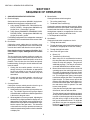
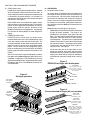
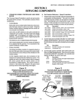
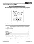
1
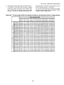
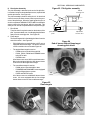
technical service manual This Technical Service Manual includes information for the following oven models: PS200/220/224 Series PS310/360 Series PS555/570 Series P/N 47829 Rev. C V1 4/02 Middleby is proud to support the Commercial Food Equipment Service Association (CFESA). We recognize and applaud CFESAs ongoing efforts to improve the quality of technical service in the industry. © 2002 Middleby Marshall, Inc. is a registered trademark of Middleby Marshall, Inc. All rights reserved. Middleby Cooking Systems Group 1400 Toastmaster Drive Elgin, IL 60120 (847) 741-3300 FAX (847) 741-4406 24-Hour Service Hotline (800) 238-8444 1 WARNING Improper installation, adjustment, alteration, service or maintenance can cause property damage, injury or death. Read the installation, operating and maintenance instructions thoroughly before installing or servicing this equipment. WARNING DISCONNECT THE OVEN FROM ITS ELECTRICAL POWER SUPPLY BEFORE SERVICING. NOTICE During the warranty period, ALL parts replacement and servicing should be performed by your Middleby Marshall Authorized Service Agent. Service that is performed by parties other than your Middleby Marshall Authorized Service Agent may void your warranty. NOTICE Using any parts other than genuine Middleby Marshall factory manufactured parts relieves the manufacturer of all warranty and liability. NOTICE Middleby Marshall reserves the right to change specifications at any time. TABLE OF CONTENTS Section 1 - Sequence of Operation .................................................... 4 I. Gas Oven Sequence of Operation ............................................. 4 II. Electric Oven Sequence of Operation ....................................... 6 F. G. H. I. J. K. Section 2 - Air Flow and Heat Transfer ............................................. 7 I. Types of Heat Transfer ............................................................... 7 II. Blowers and Blower Speed ....................................................... 7 A. PS200-series ovens ............................................................ 7 B. PS360-series ovens ............................................................ 8 C. PS555/570-series ovens .................................................... 8 III. Air Fingers ................................................................................... 8 A. Description and Function .................................................... 8 B. Configuration and Alignment ............................................... 9 C. Performing a Test Bake ....................................................... 9 D. PS300/350 Air Finger Shutter Adjustment ......................... 10 IV. Oven Capacity ............................................................................ 12 A. Conveyor Speed and Bake Time ....................................... 12 B. Belt Time .............................................................................. 12 C. Time of Delivery (TOD) ....................................................... 12 Section 3 - Troubleshooting and Servicing Components I. Conveyor Speed Controller and Drive Motor ............................. 13 A. Part Number Reference - Speed Controllers .................... 13 B. Part Number Reference - Pickup Assemblies ................... 14 C. Preparing to Service the Speed Controller ........................ 14 D. Controller/Motor Failure ...................................................... 15 E. Basic Troubleshooting Flowcharts ................................... 16 If the Conveyor Runs at Full Speed ......................... 16 If the Conveyor Will Not Run at All .......................... 17 II. 2 Initial Troubleshooting ......................................................... 18 Conveyor Control Pickup Test ............................................ 19 Conveyor Motor Test .......................................................... 19 Replacing the Magnetic Pickup .......................................... 19 Unshielded Pickup Wires on Early PS360-series Ovens . 19 Appendices ......................................................................... 20 Conveyor sensor wiring changes for PS360-series and PS570S, 10/95 .................................................... 20 Service Bulletin MM-133B - Installation Instructions for Conveyor Speed Controller Kit with Thumbwheel, P/N 42810-0133, 4/95 ................................................ 21 Instructions for Service Kit 42810-0133- Conveyor Speed Controller Kit with Thumbwheel, 4/95 .......... 23 Service Bulletin MM-177 - Introduction and Compatibility of Conveyor Speed Controller with Digital Display, P/N 37337, 8/00 ........................................... 27 Instructions for Service Kit 44756 - Conveyor Speed Controller Kit for PS200R68-series Ovens, 2/02 ... 28 Service Bulletin MM-189 - New Conveyor Gear Motors, Brushes, and Pickup Clamps, 8/01 ............ 29 DIP switch settings for Conveyor Speed Controller with Digital Display (P/N 37337), 4/02 ..................... 30 Temperature Controller ............................................................... 30 A. Part Number Reference - Temperature Controllers .......... 31 B. Description .......................................................................... 32 C. High Limit/Cooldown Functions .......................................... 32 D. Troubleshooting .................................................................. 32 E. Appendices ......................................................................... 32 Temperature Controller Terminal Cross-Reference, 4/02 .............................................. 32 Instructions for Service Kit 47321 - Digital Temperature Controller Kit, 2/02 .............................. 33 Service Bulletin MM-136 - Electrical Noise Filter Capacitor Assembly on Temperature Controllers, 9/93 ............................................................................. 43 TABLE OF CONTENTS (continued) III. High Limit Control Module ........................................................... 45 A. Part Number Reference - High Limit Control Modules ...... 45 B. Location .............................................................................. 45 C. Troubleshooting .................................................................. 45 D. Appendices ......................................................................... 46 Instructions for Service Kit 39733 High Limit Conversion Kit for PS300, 310, 350 & 360 Ovens, 5/99 ..............................................46 IV. Thermocouples ........................................................................... 54 A. Part Number Reference - Thermocouples ........................ 54 B. Thermocouple Functions ....................................................54 C. Troubleshooting .................................................................. 54 D. Appendices ......................................................................... 56 Instructions for Service Kits 33984 and 33985 Oven Thermocouple Kit, 11/01 ................................. 56 V. Blowers .................................................................................... 68 A. PS200-series ovens ........................................................... 68 B. PS360-series ovens ........................................................... 74 C. PS555/570-series ovens ................................................... 76 VI. Blower Motor Centrifugal Safety Switch (PS360-series) ....... 80 A. Part Number Reference - Blower Centrifugal Switch ...... 80 B. Troubleshooting .................................................................. 80 VII. Burner Blower Motor Centrifugal Safety Switch (PS200series gas, PS310, PS314, PS360, PS360WB, PS570S) ......... 80 VIII. Air Pressure Safety Switch (PS200-series, PS555/570series, PS360EWB, PS360WB70) ............................................. 81 A. Part Number Reference - Air Switches ............................81 B. Troubleshooting .................................................................. 82 C. Appendices ......................................................................... 83 Instructions for Service Kits 35624 and 35625 Air Pressure Switch Replacement Kits, 1/97 ..........83 Instructions to Replace an Alternate Air Switch P/N 36194 with Service Kit P/N 35624, 3/97 ........... 85 IX. PS570/570S Flame Gate ............................................................. 87 A. Part Number Reference - Flame Gate ............................... 87 B. Flame Gate Orientation ....................................................... 87 X. Gas Train and Burner System ................................................... 88 A. Part Number Reference - Gas Train Components ............ 88 B. Part Number Reference - Gas Orifices and Gas Conversion Kits .................................................................. 91 C. Component Identification ....................................................92 D. Pilot/Ignitor Assembly ..........................................................93 E. Burner Blower Motor ..........................................................95 F. Air Shutter ........................................................................... 95 G. Burner Transformer ........................................................... 96 H. Burner Motor Relay ............................................................ 96 I. High Flame Solenoid Valve ................................................. 96 J. Bypass (Low Flame) Orifice ............................................. 96 K. Modulating Gas Valve ......................................................... 97 L. Amplifier Board ................................................................... 97 M. Combination Gas Control Valve ......................................... 98 N. Ignition Module .................................................................... 99 O. Gas Conversion Kits ....................................................... 100 P. Burner and Gas Train Troubleshooting .......................... 100 Q. Checking the Gas Pressures .......................................... 102 R. XI. 3 Troubleshooting Flowcharts ........................................... 103 Intermittent Pilot System Troubleshooting Table 103 No Spark, System Does Not Work ........................ 104 Spark is Present, Pilot Will Not Light ................... 105 Pilot Lights, Main Valve Will Not Come On ......... 106 S. Appendices ...................................................................... 107 Instructions for Service Kit 42810-0117 Pilot/Ignitor Kit, 7/91 ............................................... 107 Instructions for Service Kit 30185 - Pilot Tee, 3/94 . 108 Instructions for Service Kit 42810-0121 Combination Gas Valve, 1/92 ................................ 112 Instructions for Service Kit 42810-0114 Ignition Module, 11/90 ............................................. 116 Position of Combination Gas Valve Components during Burner Operation, 4/02 ................................ 118 Instructions for All Gas Conversion Kits for Ovens with Wayne Burner, Natural Gas to Propane, 8/00 ........................................................... 119 Instructions for All Gas Conversion Kits for Ovens with Wayne Burner, Propane to Natural Gas, 8/00 ................................................... 125 Instructions for Service Kit 36856 - Gas Conversion Kit for PS360EWB/WB70 with Midco Burner, Natural Gas to Propane, 1/98 ....... 131 Instructions for Service Kit 36863 - Gas Conversion Kit for PS360EWB/WB70 with Midco Burner, Propane to Natural Gas, 1/98 ....... 135 Equivalent Orifice Sizes at High Altitudes, 4/02 . 139 Electric Oven Heating System ................................................ 140 A. PS200-series ovens ........................................................ 140 B. PS310/360-series ovens ................................................ 142 C. PS555 ovens .................................................................... 144 D. Electric Oven Mercury Contactor Replacement ............ 146 Section 4 - Electrical Wiring Diagrams ............................................ I. Component Wiring .................................................................... A. Temperature Controllers .................................................. B. Ignition Modules ............................................................... II. PS200-series Ovens ............................................................... III. PS310/360-series Ovens ........................................................ IV. PS555/570-series Ovens ........................................................ 149 149 149 150 151 160 166 Section 5 - Reference ..................................................................... 25-point preventative maintenance checklist ....................... Fractional inches to decimal and millimeter equivalents ... Decimal equivalents of drill sizes ......................................... General conversion factors ................................................... Pressure conversions ............................................................ Pressure conversion chart ..................................................... Ohms Law equation wheel .................................................... Common electrical wiring diagram symbols ........................ 172 172 173 173 174 174 175 175 176 SECTION 1 - SEQUENCE OF OPERATION SECTION 1 SEQUENCE OF OPERATION I. GAS OVEN SEQUENCE OF OPERATION D. Blower Switch A. Electrical Supply Closing the blower switch energizes: Gas heated ovens operate on 208/240V, single phase. Standard incoming power configurations are: 1. The cooling (axial) fan(s). 1. 4-wire system (PS200 series, PS310/360 series, PS570, PS570S) - 2 single phase 208/240V supply (hot) lines, 1 neutral and 1 ground. Closing this contactor starts the blower motor(s). When both blower motors are up to speed, centrifugal switches located inside the blower motors (or air switches detecting blower operation, as appropriate for the oven model) will close, setting up the heat circuit. 2. The blower motor contactor (s). 2. 3-wire system (PS360WB70, PS360EWB, PS555, PS570G, PS536) - 2 single phase 208/240V supply (hot) lines and 1 ground. 3. The Temperature Controller. For all wiring configurations, the voltage when measured from either hot line to neutral should never exceed 130V. E. Heat Switch Closing the heat switch completes a circuit: B. Door Switch 1. Through the heat switch. Closing the control cabinet door (or machinery compartment door, as appropriate for the oven model) will close the door switch and allow the oven to operate. 2. Through the blower motor centrifugal switches (or air switches, as appropriate for the oven model). 3. Through the high limit switch. Note that the electrical systems will still be live if the switch is open, although the oven cannot operate. 4. One circuit then goes to the: a. Burner (L1). The door switch has a bypass position to enable service operation with the door opened. When the door is open, grasp the switch actuator and pull it out as far as possible. This will close the door switch and permit troubleshooting. Closing the control cabinet door will reset the switch. b. Transformer (110V to 24V). c. Motor relay coil. On a cold start the heater on this relay takes about 30 seconds to warm up before the relay will energize. This gives an additional prepurge. The relay is not used on ovens with 208/240V burner blower motors. 1. Closing the door switch permits a circuit to go through a fuse (or circuit breaker, as appropriate for the oven model) to one side of the conveyor switch, blower motor switch, cooldown relay and heat switch. d. Burner blower motor. As the motor reaches full operating speed, the centrifugal switch (or air flow switch, as appropriate for the oven model) closes and applies voltage to the burner control. This energizes the ignitor control spark transformer and the pilot valve. The spark then lights the pilot. The flame sensor proves the presence of the pilot flame, and the ignitor control then shuts off the spark. At the same time, the main burner valve is opened. The main burner is then ignited. 2. Closing the door switch permits a circuit to go through the motor fuse (two 9A or 15A fuses per motor). C. Conveyor Switch Closing the conveyor switch permits a circuit to go to the Conveyor Speed Control Module, which: If the pilot does not light within approximately 90 seconds, the oven will shut down. 1. Sends power to the gear motor (conveyor drive motor). The 120VAC signal to the Conveyor Speed Control Module is rectified to a 90VDC signal which is then sent to the gear motor. The pilot and main gas valve will stay on (open) as long as the heat switch is ON and the flame is proven. If the flame goes out for any reason, the pilot will try to light for 90 seconds, and then go into automatic lockout. To relight the pilot after it has gone into automatic lockout, the burner must be turned OFF for 5 minutes and then turned ON again. 2. Allows regulation of conveyor speed. Adjusting the thumbwheel (or digital pushbutton display unit, as appropriate) to the desired conveyor belt speed instructs the Conveyor Speed Control Module to regulate the output to the gear motor. This increases or decreases the conveyor speed as necessary to match the speed setting shown on the thumbwheel or display unit. 4 SECTION 1 - SEQUENCE OF OPERATION e. For ovens with an On-Off gas regulation system (with solenoid valve): Temperature Controller terminals 4 & 5 (power for the primary relay contacts for the high flame solenoid valve). F. High Limit NOTE: Most PS200-Series and PS360-series gas ovens use the high limit feature of the Temperature Controller. All other oven models use a separate High Limit Control Module. Refer to the wiring diagram for the appropriate oven model to check whether a separate High Limit Control Module is used. For PS360EWB ovens with a modulating gas system and Temperature Controller P/N 32571: Temperature Controller terminals 4 & 5 (input signal to amplifier board). The high limit relay will shut the oven burner OFF: For all other ovens with a modulating gas system: Temperature Controller terminals 15 & 16 (input signal to amplifier board). 1. If the high limit thermocouple senses an oven temperature above 650°F. 2. If the signal from the high limit thermocouple is lost. In all ovens, the temperature-sensing thermocouple(s) send a millivolt signal to the temperature controller. As long as the temperature inside the oven is below the set point of the Temperature Controller, the Controller will do the following: An indicator on the Temperature Controller will show a high limit condition. This indicator varies by Temperature Controller model. Refer to the instructions for the appropriate Temperature Controller for an illustration and description of this indicator. 1. For ovens with an On-Off gas regulation system: If the temperature sensed by the thermocouple(s) is below the set point on the Temperature Controller, the Controller energizes the high flame solenoid. When the solenoid is energized, the solenoid valve permits 100% gas flow. Power to the solenoid is cut when the temperature reaches the set point, which closes the valve. This permits on-off gas flow to the burner. G. Cooldown NOTE: PS200VL-series ovens do not include a cooldown feature. When the heat and blower Switches are turned OFF the cooldown relay will allow the blowers to remain ON until the oven temperature falls to 200°F (93°C). During cooldown, the Temperature Controller will continue to show the oven temperature. When power is cut to the high flame solenoid, the burner will remain ON in the low flame mode. When the temperature drops a few degrees, the Temperature Controller will again energize the high flame solenoid, which opens the valve and restores gas flow to 100%. An indicator on the Temperature Controller will show whether the high flame solenoid is energized (or whether the burner is activated, which is effectively the same). This indicator varies by Temperature Controller model. Refer to the instructions for the appropriate Temperature Controller for an illustration and description of this indicator. 2. For ovens with a modulating gas system: In response to the signal from the thermocouple(s), the Temperature Controller sends a 4-20mA signal to the amplifier board. The amplifier board converts this to a 0-20VDC signal which is sent to the modulating gas valve. The valve opens or closes in proportion to the signal from the amplifier board, allowing the gas flow to be regulated as required from 0-100%. An indicator on the Temperature Controller will show whether the burner is activated. This indicator varies by Temperature Controller model. Refer to the instructions for the appropriate Temperature Controller for an illustration and description of this indicator. 5 SECTION 1 - SEQUENCE OF OPERATION ll. E. Heat Switch Closing the heat switch completes a circuit: ELECTRIC OVEN SEQUENCE OF OPERATION A. Electrical Supply 1. Through the heat switch. 2. Through the blower motor centrifugal switch. Most electrically heated ovens operate on a 208/230/ 380/440V, 3 phase, 4 wire system. The fourth wire is for a 120 V neutral ground. This 120 V neutral ground eliminates the need for a control transformer. Where a neutral is not available, a 240/110V transformer is supplied. 3. Through the high limit switch. 4. For ovens with on On-Off heater activation mode: To the primary relay contacts of the Temperature Controller (terminals 4 and 5 for digital controllers, terminals 5 and 6 for analog controllers). When the temperature-sensing thermocouple(s) indicate that the oven temperature is below the set point on the Temperature Controller, the Temperature Controller will energize the contactor(s) which in turn energize the heaters. B. Door Switch Closing the control cabinet door (or machinery compartment door, as appropriate for the oven model) will close the door switch and allow the oven to operate. Note that the electrical systems will still be live if the switch is open, although the oven cannot operate. When the oven temperature reaches the set point of the Temperature Controller, the Temperature Controller will cut power to the heaters. When the temperature drops a few degrees, the Temperature Controller will again energize the heaters. An indicator on the Temperature Controller will show whether the Controller is calling for heat. This indicator varies by Temperature Controller model. Refer to the instructions for the appropriate Temperature Controller for an illustration and description of this indicator. 5. For ovens with a Variable Pulse heater activation system: To terminals 15 and 16 on the temperature controller. In response to the signal from the thermocouple(s), Terminals 15 and 16 send a 420mA signal to a controller module that contains an amplifier board and two solid state relays. The relays activate the heating elements at 100% power on a fixed cycle time, for a length of time proportional to the signal from the temperature controller. The door switch has a bypass position to enable service operation with the door opened. When the door is open, grasp the switch actuator and pull it out as far as possible. This will close the door switch and permit troubleshooting. Closing the control cabinet door will reset the switch. Closing the door switch permits a circuit to go through a fuse (or circuit breaker, as appropriate for the oven model) to one side of the conveyor switch, blower motor switch and to the heat switch. C. Conveyor Switch Closing the conveyor switch permits a circuit to go to the Conveyor Speed Control Module, which: 1. Sends power to the gear motor (conveyor drive motor). The 120VAC signal to the Conveyor Speed Control Module is rectified to a 90VDC signal which is then sent to the gear motor. A HEAT ON indicator on the Temperature Controller will light to show whether the Controller is calling for heat. F. High Limit 2. Allows regulation of conveyor speed. Adjusting the thumbwheel (or digital pushbutton display unit, as appropriate) to the desired conveyor belt speed instructs the Conveyor Speed Control Module to regulate the output to the gear motor. This increases or decreases the conveyor speed as necessary to match the speed setting shown on the thumbwheel or display unit. NOTE: Electric oven models use a separate High Limit Control Module. The High Limit relay will shut the oven burner OFF: 1. If the high limit thermocouple senses an oven temperature above 650°F. 2. If the signal from the high limit thermocouple is lost. An indicator on the Temperature Controller will show a high limit condition. This indicator varies by Temperature Controller model. Refer to the instructions for the appropriate Temperature Controller for an illustration and description of this indicator. D. Blower Switch Closing the blower switch energizes: 1. The cooling (axial) fan(s). 2. The blower motor contactor (s). Closing this contactor starts the blower motor(s). When both blower motors are up to speed, centrifugal switch(es) located inside the rear end of the motor(s) (or air flow switch[es], as appropriate for the oven model) will close, setting up the heat circuit. G. Cooldown When the heat and blower switches are turned OFF the cooldown relay will allow the blowers to remain ON until the oven temperature falls to 200°F (93°C). 3. The Temperature Controller. 6 During cooldown, the Temperature Controller will continue to show the oven temperature. SECTION 2 - AIR FLOW AND HEAT TRANSFER SECTION 2 AIR FLOW AND HEAT TRANSFER I. In Middleby Marshall conveyor ovens, the heat transfer from conduction is greatly dependent on the customers product and cooking surface (pans, etc.). Likewise, the heat transfer from radiation is effectively constant, because the color of the oven interior cannot be changed. For these reasons, the best way to optimize heat transfer is by regulating the convection air. This can be done in two ways: TYPES OF HEAT TRANSFER Heat constantly moves from a warm object to a cold object. Heat moves in three different ways: thorough conduction, through radiation, and through convection. Middleby Marshall conveyor ovens use all three of these paths to cook the product. Conduction - Heat is transferred through surface contact (such as pizza dough in contact with a pan). Radiation - Heat is transferred from light-colored objects to dark-colored objects. The darker the color of an object, the greater the amount of heat that it absorbs. The lighter the color of an object, the greater the amount of heat that it reflects. Middleby ovens use light-colored interiors (aluminized or stainless steel, depending on the oven model) to reflect as much heat as possible to the product. Adjusting the blowers and blower speed to change the quantity and velocity of air delivered onto the product. Adjusting the air finger configuration to change the pattern in which the vertical columns of air are delivered to the product. II. BLOWERS AND BLOWER SPEED A. PS200-series ovens PS200-series ovens have a single blower motor mounted inside the machinery compartment, with a pulley on the end of the motor shaft. A belt connects this pulley to another on the shaft of the blower fan. The air velocity can be changed by using a larger or smaller pulley on the motor shaft, and changing the length of the belt to match the new pulley. See Figure 1. Convection - Heated air will transfer heat to objects with which it comes into contact. Unless the air flow is controlled, hot air will rise and be replaced by cooler air. Middleby Marshall ovens use blowers (one or two large fans, depending on the oven model) to force air through adjustable air fingers onto the product. However, note that there are only two approved belt/ pulley combinations for PS200-series ovens; one for 60Hz ovens, and one for 50Hz ovens. Field modifications to these approved combinations are not permitted unless under the specific directions of the Middleby Technical Service Department. Any changes to convection air delivery MUST be made using the air fingers. The intensity of the heat at the point at which it is sensed is called temperature. The difference in temperature between the food product and the heat source - that is, the pan, oven interior, or heated air, as described above - determines the speed at which the heat flows. The greater the difference in temperature, the faster the heat flows to the product. Figure 1 Blowers, belts and pulleys PS200-series PS360-series PS555/570-series Early (PS570) Current (PS570S, PS570G, all PS555) Blower Wheel Orientation 7 Blower Wheel Orientation SECTION 2 - AIR FLOW AND HEAT TRANSFER III. AIR FINGERS B. PS360-series ovens A. Description and Function PS360-series ovens feature two blower motors. A blower wheel is fastened onto the end of the motor shaft. In order to adjust the amount and speed of heated air that is directed by the blower wheels, it is necessary to change the size of the wheels and/or change the speed of the motor. See Figure 1. Air fingers direct the heated air from the blowers into vertical jets that are directed at the top and bottom of the conveyor belt. Each air finger configuration has been tested to optimally cook a specific customers product. As a rule, air finger configurations should NOT be changed from customer specifications without direct instructions from the Middleby Technical Services Department. Each PS360-series oven model has a specific combination of blower motor and blower wheel. Field modifications to these approved combinations are not permitted unless under the specific directions of the Middleby Technical Service Department. Any changes to convection air delivery MUST be made using the air fingers. Middleby uses two main types of air fingers: PS300/350 and early PS310/360 ovens used a shutter-type air finger assembly. The finger is assembled from a manifold, inner plate and outer plate. The inner plate is assembled from two separate plates, each with a series of holes, that are riveted together. The plates can be repositioned relative to each other to restrict the air flow through the holes as necessary. These fingers are no longer in general use, but may still be found in older ovens in the field. See Figure 3. All current ovens use an air finger which is composed of a manifold, inner plate, and outer plate. No adjustments are necessary or possible to these fingers, but a wide variety of styles is available to meet different customers baking needs. See Figure 4. C. PS555/570-series ovens PS555/570-series ovens have one blower motor mounted inside each of the end compartments of the oven, with a pulley on the end of the motor shaft. The oven has two blower wheels; a belt connects each motor pulley to a pulley on the end of one of the blower wheel shafts. The air velocity can be changed by using a larger or smaller pulley on the motor shaft, and changing the length of the belt to match the new pulley. See Figure 1. Some customers have a specific belt/pulley combination approved by Middleby Marshall, while others use a standard configuration. Field modifications to these approved combinations are not permitted unless under the specific directions of the Middleby Technical Service Department. Figure 3 PS300/350 air finger with shutter plate Outer plate Lower air fingers have wire rack as shown to prevent conveyor belt from rubbing on outer plate. Figure 2 Air finger operation Rivets Inner plate Shutter Hot air flow from blower wheel(s) Manifold Figure 4 Current standard air finger (all oven models) Vertical columns of high-velocity hot air Outer plate Width and hole configuration varies. Inner plate Width and hole configuration varies. May have inner dam. 8 Manifold Width varies to match inner and outer plates. Baffle may be solid, perforated, partially perforated, or absent. Several special shapes are available to meet specific customer needs. SECTION 2 - AIR FLOW AND HEAT TRANSFER IV. OVEN CAPACITY B. Belt Time Oven capacity is generally not a service issue. However, when reporting a service problem, customers may use terms relating to capacity, such as bake time, belt time, time of delivery, etc. This information is provided as a reference for understanding these terms. Belt Time is a measurement used by several customers. It is a trailing edge to trailing edge measurement. That is, it is the elapsed time from the trailing edge of the product entering the bake chamber to the trailing edge of the product leaving the bake chamber. See Figure 10. A. Conveyor Speed and Bake Time Note that belt time is equal in length to conveyor speed (bake time), although the time is measured during a different period of the baking process. Middleby Marshall conveyor ovens display the Conveyor Speed on the Thumbwheel (or on the display of the Digital Speed Controller, as appropriate for the oven model). Conveyor Speed is also called Bake Time. C. Time of Delivery (TOD) Conveyor Speed (Bake Time) is a leading edge to leading edge measurement. That is, it is the elapsed time from the leading edge of the product entering the bake chamber to the leading edge of the product leaving the bake chamber. See Figure 9. Time of delivery (TOD) is a leading edge to trailing edge measurement. That is, it is the elapsed time from when the leading edge of the product enters the bake chamber to when the trailing edge of the product leaves the bake chamber. See Figure 11. Figure 9 - Conveyor Speed (Bake Time) Figure 10 - Belt Time Conveyor Speed (Bake TIme) Belt Time Direction of Conveyor Travel Leading edge of product Direction of Conveyor Travel Trailing edge of product Figure 11 - Time of Delivery Time of Delivery Direction of Conveyor Travel Trailing edge of product Leading edge of product D. Formulas for Determining Time of Delivery (TOD) and Oven Capacity per Hour 1. Time of Delivery (TOD) Time of Delivery (TOD) = Conveyor Speed x Bake Chamber Length (Bake Chamber Length + Product Diameter) Example: PS570S Oven, 7:00 Bake Time, 16 Product Diameter = 2. Oven Capacity/Hour Oven Capacity/Hour = 7 mins. x (70 + 16) = 8.6 mins. (8:36) 70 (Bake Chamber Length + Product Diameter) x Bake Chamber Depth Product Diameter² Example: PS570S Oven, 7:00 Bake Time, 16 Product Diameter = 12 x 60 min./hr. TOD (70 + 16) x 32 x 6.98 = 75 pizzas/hr. 256 in.² SECTION 3 - SERVICING COMPONENTS Figure 16 Current pickup assembly - side view Figure 17 Current pickup assembly end view Components needed for the field tester: Full-wave AC-DC bridge, 400V, 4A Light dimmer switch, 5A In-line 5A AC fuse enclosed in plastic case 2 alligator clips D. Controller/Motor Failure When the conveyor speed controller fails, it is very possible that a shorted conveyor motor caused the problem. Unless the motor is changed, the installation of another conveyor speed controller will simply burn up the new controller. CAUTION: DO NOT turn the conveyor switch ON while the field tester is connected! You are STRONGLY ADVISED to bypass the speed controller and install the tester unit shown in Figure 18 before replacing any speed controller that has burned out. This will identify the source of the problem - the speed controller or the motor. It is much less expensive to burn out the tester than another speed controller. 1. Disconnect the motor lead wires and attach to the field tester as shown in Figure 18. Depending on the oven model, you can simply use the black and red gear motor leads, or the remote leads at the terminal block connection. The components for this tester can be purchased at any electrical supply store. The tester is not as accurate or sensitive as the speed controller, and so should NOT be left in place on the oven after servicing! To reverse the conveyor motor direction, simply interchange the black and red leads. 2. To start the test, the dimmer switch should be turned until the motor begins to operate. The switch can then be turned down to the desired motor speed. Figure 18 Field Tester for Conveyor Drive Motor or circuit breaker 15 SECTION 3 - SERVICING COMPONENTS Figure 24 - Thermocouples IV. THERMOCOUPLES All temperature controller and high limit functions are based on input from thermocouples. When two wires composed of dissimilar metals are joined together and one of the ends is heated, a continuous current flow is generated. Middleby ovens use a Type J (iron constant) thermocouple. The iron wire increases the number of dissimilar metal junctions in the circuit. Middleby has used several types of thermocouples. All can be replaced with the current version. Refer to Figure 24 for illustrations. A two-lead thermocouple with a small retaining clip. Used for EITHER temperature-sensing OR high-limit functions. This type is no longer available. A four-lead thermocouple with a small retaining clip. This is a dual-function unit that sends its signal to the temperature controller and to a separate high limit control module. This type is no longer available. A three-lead thermocouple with a separate ground lead, a shielded cable and a large mounting flange. This is the only type of thermocouple available from Middleby at this time. If it is used to replace a four-lead dualfunction thermocouple, two complete and separate thermocouples will have to be installed. Current 3-lead thermocouple Obsolete 2-lead or 4-lead thermocouple Cable (2 or 4 leads) clip A. Part Number Reference - Thermocouples Part numbers are provided ONLY for the current, 3-lead thermocouple kits. These thermocouples include instructions for replacing all previous thermocouple designs, in all oven models. P/N Description 33984 Kit, thermocouple, PS360-series or PS555/570 series 33985 Kit, thermocouple, PS200-series or PS536 B. Thermocouple Functions 1. Temperature-sensing thermocouple(s) All thermocouples monitor oven temperature. However, Middleby uses the term temperature-sensing thermocouple in reference to thermocouples that send their signal to the temperature controller instead of to a separate high limit control module. On ovens that do NOT include a separate high-limit control module (this includes most PS200-series and PS360-series gas ovens), this thermocouple signal is used to monitor the oven temperature for regulating the gas flow/heater activation, AND to activate the high limit warning in case of an overtemp condition. Middleby ovens use from one to three temperature-sensing thermocouples, depending on the oven model. Temperature-sensing thermocouples are used on all oven models and are connected to Terminals 7 and 8 on the temperature controller. Based on the signal from this thermocouple, the temperature controller: Calls for heat from the burner/heating elements to maintain the set point (output from Terminals 4 & 5 for on-off electric and gas ovens; output from Terminals 15 & 16 for variable pulse electric and modulating gas ovens). Controls the cooldown feature if the HEAT switch is turned off while the oven is above the cooldown temperature (output from Terminals 9 & 10). On ovens without a separate high limit control module (most PS200-series and PS360-series gas and electric ovens), the oven temperature sensed by this thermocouple is also used to activate the high limit warning (output from Terminals 11 & 12). Cable (3 leads) flange 2. High limit thermocouple Middleby uses the term high limit thermocouple in reference to the thermocouple that sends its signal solely to the separate high limit control module. If the oven does not have a separate high limit control module, there is no high limit thermocouple. On these ovens, the temperature-sensing thermocouple(s) control high limit activation. C. Troubleshooting 1. Open thermocouple An open in a thermocouple will cause the temperature controller to read the maximum temperature (usually 909°F/487°C). This causes the following: On ovens without a separate high limit control module, an open thermocouple triggers the high limit alarm. This shuts down the burner. After the open has been corrected, the high limit will need to be reset to allow the oven to resume operation. On ovens with a separate high limit control module, an open temperature-sensing thermocouple causes the temperature controller to stop calling for heat. This shuts down the burner. On ovens with a separate high limit control module, an open high limit thermocouple will trigger the high limit control module to shut down the burner. Note that the high limit control will need to be reset after the open is corrected before the oven can return to operation. 54 SECTION 3 - SERVICING COMPONENTS 2. Checking the thermocouple with a DC millivolt meter It is possible to check that a thermocouple is reading accurately by using a multimeter set to read DC millivolts. At 32°F/0°C the thermocouple should read 0 mVDC. This can be checked by inserting the ther- mocouple into an ice bath for several minutes. At 72°F/ 22°C the reading should be 1.134mVDC. You can use the chart below by checking the temperature at the thermocouples junction terminals. This is called the Junction Temperature. Figure 24 - Thermocouple millivolt readings at various operating and junction temperatures 55 SECTION 3 - SERVICING COMPONENTS Figure 63 - Pilot/ignitor assembly D. Pilot/Ignitor Assembly The pilot assembly is attached to the end of the pilot line. It consists of an ignitor electrode/flame sensor, a pilot shield and the pilot burner. See Figure 63. Pilot line connects here Pilot burner The pilot assembly includes a safety circuit. An electrical current is sent to the flame sensor probe to prove the presence of the pilot flame. When the spark ignites the pilot, a circuit is completed THROUGH THE FLAME from the flame sensor probe to the pilot burner, which is grounded. This safety circuit must be completed before the pilot will light. Hood 1. Pilot Shield The pilot shield is a plate located on the bottom of the pilot. It prevents drafts, etc. from blowing the pilot flame away from the sensing probe. See Figure 64. Ignitor/sensor probe Spark cable connects here 2. Flame target The flame target aids in distributing the flame from the end of the venturi. See Figure 65. PS310/360-series ovens built prior to 6/87 are not equipped with a flame target. The burner on these ovens resembles the one shownin Figure 64. The angled flame target is used on: - PS200-series ovens built through 3/02. - PS310, PS314, PS360 and PS360WB ovens built 6/87 or later. - PS570S ovens. All of these ovens use a 120V burner blower motor. Most units equipped with the 120V burner blower motor also use the angled flame target. The round flame target is used on: - PS200-series ovens built 4/02 or later. - PS360EWB and PS360WB70 ovens equipped with the Wayne burner system. - PS555 and PS570G ovens. All of these ovens use a 208/240V burner blower motor. All ovens equipped with the line voltage burner blower motor use the round flame target. Figure 64 End of burner without flame target showing pilot shield Pilot shield Figure 65 Flame targets Angled target Round target 93 SECTION 3 - SERVICING COMPONENTS 3. Pilot and Proof of Pilot Flame Rectification With standing pilots, heat is a necessary ingredient for proper thermocouple operation. But this is not the case with IIDS (Intermittent Ignition Device Systems) when flame conduction or rectification is used. To better understand the principles of flame conduction and rectification, we must first understand the structure of a gas flame. See Figure 66. Figure 66 Flame structure Figure 67 - Flame rectification Figure 68 - Pilot and probe With the proper air-gas ratio to give a blue pilot flame, three zones exist. Zone 1: An inner, fuel-rich cone that will not burn because excess fuel is present. Zone 2: Around the inner, fuel-rich cone is a blue envelope. In this area is a mixture of vapor from the fuel-rich inner cone and the secondary, or surrounding, air. This is where combustion occurs. Zone 3: Outside the blue envelope is a third zone that contains an excessive quantity of air and will not burn. Of concern is the second, or combustion area. This is where the burning occurs and is the area that is of prime importance for good flame sensor location. Flame Rectification With flame rectification, two probes with different surface areas are exposed to a flame - in this case, the pilot flame. The probe with the larger surface area attracts more free electrons and, as a result, becomes the negative probe. Therefore, current is conducted through the flame from the positive probe to the negative probe. See Figure 67. THE FOLLOWING CONDITIONS WILL HAVE A DIRECT BEARING ON EVERY IID APPLICATION: Voltage Note also that the AC voltage sine wave has not changed, but the negative portion of the current sine wave has been chopped off. This positive portion now represents a DC current. This is the phenomenon of flame rectification. The supply voltage to the ignition controls should be within the following ranges: 120VAC controls 102 to 132VAC 24VAC controls 21 to 26.5VAC 24VAC systems should use transformers that will provide adequate power under maximum load conditions. To apply this principle to an IID (Intermittent Ignition Device - in this case, the pilot/ignitor assembly), a pilot and flame sensor have been substituted for the two probes (See Figure 68). After the pilot is ignited, a DC current flow of 2.0mA (microamps) or more is conducted through the flame, from the flame sensor (the positive probe) to the pilot tip (the negative probe). The pilot tip, acting as the negative probe, completes the circuit to ground. The IID sensing circuit uses this DC current flow to energize a relay and open the main burner gas valve. Gas Pressure Inlet gas pressures Natural gas, Wayne burner - 6-12 W.C. (14.9-29.9 mbar) Propane, Wayne burner - 11½-12 W.C. (28.7-29.9 mbar) Midco burner (all gases) - 6-14 W.C. (14.9-34.9 mbar) Regulated gas pressures Natural gas, Wayne burner - 3.5 W.C. (8.7 mbar) Propane, Wayne burner - 10 W.C. (24.9 mbar) Midco burner (all gases) - 3-5 W.C. (7.5-12.5 mbar) Pilot gas pressures 94 Natural gas, Wayne burner - 3½-4 W.C. (8.71-9.95 mbar) Propane, Wayne burner - 8-10 W.C. (19.9-24.9 mbar) Midco burner (all gases) - 5-6 W.C. (12.5-14.9 mbar) SECTION 3 - SERVICING COMPONENTS Temperature Ignition controls should not be exposed to temperatures exceeding 140°F (60°C) or less than -40°F (-40°C). Pilot Application The pilot and flame sensor application is the most critical aspect of the llD application. The pilot flame must make contact with the pilot tip and surround the flame sensor probe. A multimeter or ampmeter set to read microamps (mA) is necessary to verify that the proper amount of current is being maintained through the pilot flame. The minimum value required is 2.0 mA. Rectification-based ignition systems respond in less than 0.8 of a second to a loss of flame. If the minimum signal is not being maintained at all times, OR if the pilot flame is briefly directed away from the flame sensor or pilot tip, the main gas valve may cycle rapidly (chattering) or the burner may be prevented from activating. Other conditions that can cause the failure of the main burner to activate, OR chattering of the burner, are: 1. Pilot flame is too small. 2. Gas pressure is too low for proper pilot flame impingement on the flame sensor. In these cases, the pilot may ignite, but the main burner gas valve will not be energized. It is also possible for drafts or unusual air currents to deflect the pilot flame away from the flame sensor. Deflection of the pilot flame may also be caused by main burner ignition concussion or roll-out of the main burner flame. An additional point to be considered is the condition of the pilot flame. If the pilot flame is hard and blowing, the grounding area of the pilot is reduced to a point where the necessary current is not being maintained, and a shutdown of the system will result. The positioning of the flame sensor is also critical in the pilot application. Positioning of the flame sensor should be such that it will be in contact with the second, or combustion area of the pilot flame. Passing the flame sensor through the inner cone of the pilot flame is not a recommended procedure. For this reason, a short flame sensor may provide a superior signal over a longer one. The final determination of the sensor location (length) is best determined by the use of a multimeter set to read microamps (mA). E. Burner Blower Motor The burner blower motor is located on the side or top of the burner housing. Some blowers use a flexible tube to connect the blower to the burner, depending on the available space inside the machinery compartment. The burner blower motor drives a blower wheel located in a housing attached to the end of the motor that is the primary air supply for combustion. The motor requires no lubrication. Depending on the oven model, the burner motor operates on either 120V or 208/240V (line voltage). 120V motors have an internal centrifugal switch that controls the 24V power supply to the gas valve (see Burner Blower Motor Centrifugal Safety Switch on Page 80). 208/240V motors use a separate air pressure safety switch to sense blower operation (see Air Pressure Safety Switch on Page 81). This safety feature prevents burner operation in case of motor failure. Figure 69 Air shutter adjustment Wayne burner Standard openings: 1/4/6.4mm for natural gas ovens 3/8/9.5mm for propane ovens Clockwise less air Loosen hex nut to adjust shutter Counterclockwise more air F. Air Shutter The air shutter is a round metal plate located on the open end of the burner blower wheel. Adjusting the position of the shutter will increase or decrease the amount of air that is permitted into the plenum for combustion. Rotate the plate in a counterclockwise direction to increase the air supply, or in a clockwise direction to reduce the air supply. You can insert a drill bit into the shutter gap to check the size of the opening. Refer to Figure 69 for the recommended opening sizes. Early Midco burners use an adjustment screw on the front wall of the plenum to adjust the airflow. If it is not possible to adjust the air supply properly using the screw, a retrofit kit is available (P/N 36829) to install the external air shutter shown in Figure 69. 95 Midco burner Standard opening 5/16/7.9mm (all gases) Clockwise less air Loosen screw to adjust shutter Counterclockwise more air SECTION 3 - SERVICING COMPONENTS The modulating valve features a bypass adjustment screw, shown in Figure 71. For all ovens except the PS536, the screw should ALWAYS remain fully closed; no adjustment is necessary. The screw is pre-set to the fully-closed position from the factory. If the screw is adjusted to any setting other than fully-closed, the oven may not be able to maintain the set point temperature. K. Modulating Gas Valve (if so equipped) Ovens that use a PID (modulated) gas regulation system are equipped with a modulating gas valve instead of a solenoid valve. The valve is located between the combination gas control valve and the burner. In response to the millivolt signal from the thermocouple, the Digital Temperature Controller sends a 4-20mA signal to an amplifer board. The board, in turn, passes on a 020VDC signal to the modulating valve itself. The valve opens or closes proportionally to the signal from the amplifier board, allowing any setting from 0-100% gas flow. IMPORTANT: For proper functioning of the modulating valve, the temperature controller MUST be set to the PID operating mode. Refer to Temperature Controller on Page 31. When the oven is switched on, gas demand is at its peak and the valve is fully open, permitting 100% gas flow. As the ovens temperature approaches the set point, the valve slowly begins to close, restricting gas flow to the 35-60% range. After the oven is fully preheated, the gas flow usually stabilizes at about 30%. The actual oven temperature can remain constant, with NO temperature swing, because the valve is adjusted constantly according to the demand. L. Amplifier Board (ovens with a modulating gas valve only) Ovens equipped with a modulating gas valve have an amplifier board mounted inside the machinery compartment. Modulating valves are used on all PS360EWB, PS555, and PS570G gas ovens. They are also used on PS200 ovens produced 4/02 or later and PS570S ovens produced 9/00 or later. In response to the millivolt signal from the thermocouple, the Digital Temperature Controller sends a 4-20mA signal to the amplifer board. The board, in turn, passes on a 020VDC signal to the modulating valve. The valve opens or closes proportionally to the signal from the amplifier board, allowing any setting from 0-100% gas flow. The Model PS360EWB oven uses a Maxitrol M520 modulating valve with a 3/4 gas line, P/N 32570. All other Middleby oven models equipped with a modulating valve use the Maxitrol M420 valve with a 1/2 gas line, P/N 41647. All Middleby oven models equipped with a modulating valve use amplifier board P/N 31651. Figure 71 - Modulating Gas System Digital Temperature Controller To transformer 24VAC input orange/white MUST BE SET TO PID OPERATING MODE orange white + To thermocouple blue red - blue/white purple/white Modulating Valve bypass adjustment screw (under cap) MUST BE FULLY CLOSED purple Amplifier Board To amplifier board terminal 6 To amplifier board terminal 5 97 purple purple/white PS360EWB with Controller 32571 only SECTION 3 - SERVICING COMPONENTS 3. Servicing the Combination Valve Pilot pressure M. Combination Gas Control Valve 1. Part Number Reference - Combination Gas Valve PS360WB70 and PS360EWB ovens are equipped with a 3/4 (19.05mm) gas line. This requires the use of Combination Gas Valve P/N 32569. The valve has a tan plastic cover with a blue On/Off knob. All other oven models are equipped with a 1/2 (12.7mm) gas line. - Through 10/01 - these ovens used Valve P/N 280920017. The valve operated on a 60 Hz supply, had a tan plastic cover and a blue On/Off knob. - 11/01 and later - these ovens use Valve P/N 45688. The valve operates on a 50 or 60 Hz supply, has a grey plastic cover and a black On/Off knob. It is otherwise identical to the previous version, and may be used to replace it in all cases. One of the more common service issues with the combination valve occurs on ovens with the on/off gas regulating system (with a solenoid valve), when the oven is on low flame. During low flame, the servo can bounce inside the valve as it searches for the proper level. The bouncing line pressure can also cause surges in the pilot pressure. A properly adjusted pilot will tend to smooth out the surges. The best way to check for a properly adjusted pilot is to check the pilot line pressure. This requires a pilot pressure tap in the pilot line. Ovens built 3/94 or later should have the tap installed in the line. The tap is also available as Service Kit P/N 30185 which includes installation instructions. Recommended pilot gas pressures are: - Wayne burner, natural gas - 3½-4 W.C. (8.71-9.95 mbar) - Wayne burner, propane - 8-10 W.C. (19.9-24.9 mbar) - Midco burner (all gases) - 5-6 W.C. (12.5-14.9 mbar) 2. Valve Operation When the ON-OFF knob on the valve is in the ON position, gas is allowed to enter the valve. Once 24VAC is supplied to the valve, gas is supplied to the pilot line. When the pilot flame has been proved (see Pilot and Proof of Flame Rectification on Page 94), 24VAC is supplied to the combination valve by the ignition module, opening the main valve. Gas pressure from the inlet side of the valve is passed through the Pressure Regulator. The regulated pressure is supplied to a cavity below the main valve diaphragm. This pressure overcomes the spring force and moves the main valve to its open position. During operation, the main valve is opened and closed by the pressure regulator to keep a constant pressure at the outlet of the valve. Burrs in pilot adjustment portal Some combination valves have been shown to have shipped with small burrs in the pilot adjustment portal. Although this will not interfere with proper operation of the valve in any way, it does make it difficult to adjust the pilot pressure until the burr is removed. Check for a burr by attaching a manometer to the pilot pressure tap. If the manometer does not detect any change in pilot pressure when the screw is tightened all the way down, there is probably a burr in the portal. When power to the valve is cut, the cavity below the main valve diaphragm is depressurized and the valve spring closes the main valve rapidly to shut off the main burner. To remove a burr, perform the following procedure: - Turn the adjustment screw all the way down. - Apply more pressure to break through the burr. - Back the screw out until the top of the screw is level with the top of the access hole. - Turn the adjustment screw back down to adjust the pressure. - Repeat these steps until the burr is cleared. When the 24VAC supply to the valve is cut, the valve stops gas flow to both the pilot and the main burner. The combination valve includes taps to measure both the inlet pressure and the regulated pressure. To ensure accuracy, the regulated pressure should be measured when the oven is on low flame. Figure 72 - Combination Gas Control Valve Pressure regulator adjustment (under cap screw) Regulated pressure tap Inlet pressure tap On/Off knob (should remain in ON position) Pilot line connection 98 Pilot pressure adjustment (under cap screw) SECTION 3 - SERVICING COMPONENTS N. Ignition Module If you are replacing the obsolete module (P/N 271610004) with the current version (P/N 27161-0005), BE SURE TO DISCONNECT THE MODULE FROM THE COMMON GROUND WITH THE TRANSFORMER AND RELAY. Double-grounding of the module creates a feedback voltage circuit that allows the module to operate without a signal from the burner/blower assembly. This procedure is explained in greater detail in the instructions for Kit 42810-0114, included in the Appendices section. 1. Part Number Reference - Ignition Module PS360WB70 and PS360EWB ovens equipped with the Midco burner use Ignition Module P/N 31501. For all other oven models: - Through 10/90 - these ovens used Ignition Module P/N 27161-0004. Some versions of this module included a separate, replaceable fuse. This module shared a common ground with the 24V transformer and the relay coil. See Figure 73. - 11/90 or later - these ovens use Ignition Module P/N 27161-0005, included in Service Kit 428100114. The module is internally grounded and the common ground with the transformer and relay coil has been eliminated. See Figure 74. 2. Module Operation The ignition module delivers 24V to the pilot ignitor when the blower motor centrifugal switch (or air pressure safety switch) is closed. When the module detects a current flow of at least 2.0 mA through the pilot flame, it supplies 24V to the combination gas control valve, allowing the valve to operate. Figure 73 Wiring diagram of ignition and gas valve system (obsolete ignition module 27161-0004) Figure 74 Wiring diagram of ignition and gas valve system (current ignition module 27161-0005) 99 SECTION 5 - REFERENCE SECTION 5 REFERENCE 25-point preventative maintenance checklist [ ] 1. Check and clean (blow out) machinery/control compartment. [ ] 2. Check and clean (blow out) main blower motors. [ ] 3. Check and clean (blow out and brush) axial fans. [ ] 4. Check burner blower motor and fan operation. [ ] 5. Check and clean igniter assembly. [ ] 6. Check and clean all orifices. [ ] 7. Install pilot tee if oven is not so equipped. [ ] 8. Check gas pressures; adjust as necessary. [ ] 9. Check air-fuel mixture; adjust as necessary. [ ] 10. Check ignition cable for signs of deterioration. [ ] 11. Check and tighten all electrical connections. [ ] 12. Inspect conveyor belt for damage; repair as necessary. [ ] 13. Inspect conveyor frame pivot plates. [ ] 14. Inspect conveyor shaft bushings - Replace drive side bushing. [ ] 15. Check conveyor drive chain tension; adjust as necessary. [ ] 16. Verify proper air finger arrangement; correct as required. [ ] 17. Inspect and clean (vacuum) conveyor motor and motor brushes. [ ] 18. Inspect conveyor motor sensor and magnet; verify correct spacing; adjust as necessary. [ ] 19. Check conveyor speed control; verify belt speed to be within 10 seconds of set point. [ ] 20. Verify that proper number of thermocouples are installed. [ ] 21. Check temperature control with thermocouple source to verify accuracy. [ ] 22. Check high limit safety circuit with thermocouple source to verify correct operation. [ ] 23. Check cool down feature with thermocouple source to verify correct operation. [ ] 24. Using the read function of the temperature controller, verify and record the high ambient reading. [ ] 25. Verify positive ignition on cold start. 172 PFBD112206 11-22-06 4 5 PFBD112206 11-22-06 Trouble Shooting Middleby Conveyor Ovens Quick Check list Modulating Gas Valve • Is Temperature Controller in PID mode? • Confirm you have 24VAC input on amplifier board are terminals 1 and 2 - if not, check transformer. • Confirm 0-20VDC output voltage at terminals 3 and 4 on the amplifier board - if not, check for 4-20mA input to amplifier board from temperature controller at terminals 5 and 6. • Confirm 4-20mA signal on terminals 5 and 6 of the amplifier board - temperature controller must be in PID mode. - Refer to Middleby Marshall Temperature Controller hand-out, section 4. Ignition Circuit PS300 Series and PS200 Series 1. The following sequence of events must happen for the oven to light. • Each of the main blower motors must either trip a centrifugal switch or an air switch. • Once the above occurs, next the transformer on the burner blower motor should be supplied voltage • Next, the time delay relay • The burner blower motor should come up to speed and trip either a centrifugal switch or an air switch. • 24 volts to the ignition module 2. 24 volts between MV/PV and PV terminals 3. Once you have a pilot, you will have 24 volts between MV/PV and MV 4. If these steps have been proven, you have completed the Ignition sequence. Conveyor Runaway Condition • Confirm distance between Sensor and Magnet – business card thickness • Check common to +5 terminals on speed control – should be 5 VDC • Check common to count terminal on speed control–2.5VDC with motor running • If a thumbwheel display, and you do not achieve proper bake time, it is most likely the contacts in the thumbwheel. Drive Motor Stopping • Confirm input to AC terminals on speed Control – should be 115 V • Confirm output voltage from ARM+ and ARM• If no voltage, disconnect one ARM, check for voltage. If you have voltage, check drive motor for shorts and also check brushes for wear. 11 PFBD112206 11-22-06 Middleby is proud to support the Commercial Food Equipment Service Association (CFESA). We recognize and applaud CFESA’s ongoing efforts to improve the quality of technical service in the industry. Middleby Marshall • 1400 Toastmaster Drive • Elgin, IL 60120 • USA • (847) 741-3300 • FAX (847) 741-4406 www.middleby.com