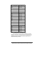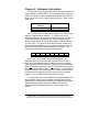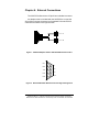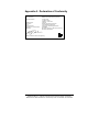
1
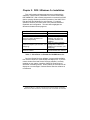
Not Recommended for New Installations.
Please contact Technical Support for more information.
PCMCIA RS-232 2-Port Card
Model 232PCC2
Documentation Number 232PCC23799
International Headquarters
B&B Electronics Mfg. Co. Inc.
707 Dayton Road -- P.O. Box 1040 -- Ottawa, IL 61350 USA
Phone (815) 433-5100 -- General Fax (815) 433-5105
Home Page: www.bb-elec.com
Sales e-mail: [email protected] -- Fax (815) 433-5109
Technical Support e-mail: [email protected] -- Fax (815) 433-5104
European Headquarters
B&B Electronics Ltd.
Westlink Commercial Park, Oranmore, Co. Galway, Ireland
Phone +353 91 792444 -- Fax +353 91 792445
Home Page: www.bb-europe.com
Sales e-mail: [email protected]
Technical Support e-mail: [email protected]
B&B Electronics -- Revised September 1999
Documentation Number 232PCC23799 Manual
Cover Page
B&B Electronics Mfg Co Inc – 707 Dayton Rd - PO Box 1040 - Ottawa IL 61350 - Ph 815-433-5100 - Fax 815-433-5104
B&B Electronics Ltd – Westlink Commercial Park – Oranmore, Galway, Ireland – Ph +353-91-792444 – Fax +353-91-792445
TABLE OF CONTENTS
CHAPTER 1: INTRODUCTION ............................................................1
SPECIFICATIONS ........................................................................................1
CHAPTER 2: DOS / WINDOWS 3.X INSTALLATION......................3
232PCC2 CLIENT DRIVER FOR DOS.........................................................4
CLIENT DRIVER INSTALLATION .................................................................4
COMMAND LINE OPTIONS .........................................................................5
COMMON PROBLEMS ................................................................................9
Identifying the 232PCC2......................................................................9
Generic Client Drivers Generic Client Drivers ...................................9
Available Resources.............................................................................9
Multiple Configuration Attempts..........................................................9
Older Versions of Card and Socket Services .......................................9
CHAPTER 3: 232PCC2 ENABLER FOR DOS...................................10
COMMAND LINE OPTIONS .......................................................................11
COMMON PROBLEMS ..............................................................................13
Identifying the 232PCC2....................................................................13
Memory Range Exclusion ..................................................................13
Socket Numbers..................................................................................14
Card and Socket Services Software....................................................14
CHAPTER 4: WINDOWS 95/98 INSTALLATION............................15
INSTALLING A 232PCC2 UNDER WINDOWS 95/98..................................15
232PCC2 RESOURCE SETTINGS IN WINDOWS 95/98...............................16
VIEWING THE 232PCC2 RESOURCE SETTINGS ........................................17
CHANGING RESOURCE SETTINGS WITH DEVICE MANAGER .....................18
CHAPTER 5: HARDWARE INFORMATION ...................................21
CHAPTER 6: EXTERNAL CONNECTIONS .....................................22
APPENDIX A: DECLARATION OF CONFORMITY.....................A-1
Documentation Number 232PCC23799 Manual
Table of Contents
B&B Electronics Mfg Co Inc – 707 Dayton Rd - PO Box 1040 - Ottawa IL 61350 - Ph 815-433-5100 - Fax 815-433-5104
B&B Electronics Ltd – Westlink Commercial Park – Oranmore, Galway, Ireland – Ph +353-91-792444 – Fax +353-91-792445
i
Chapter 1: Introduction
B&B Electronics 232PCC2 provides two independent RS-232
asynchronous serial communications interfaces for systems
equipped with PCMCIA Type II and/or Type III expansion sockets.
The 232PCC2 is a PCMCIA Type II (5 mm) card and is PCMCIA PC
Card Standard Specification 2.1 compliant.
The 232PCC2's serial ports are implemented using 16C550
Universal Asynchronous Receiver/Transmitters (UARTs) that are the
recommended communications interface for multitasking
environments and applications involving high data transfer rates.
The 232PCC2’s two serial ports are addressable in two modes:
1. Block Mode: The two serial ports are configured in one 16-byte
continuous block of I/O address space. The block must begin
on an even 16-byte division. Both serial ports share one IRQ
level.
2. COM Mode: The two serial ports are configured at the standard
COM port I/O address location. The ports may be configured as
COM1 and COM3; also, the ports may be configured as COM2
and COM4. Both serial ports share one IRQ level.
A special interrupt status register is also available to simplify the
software required to service multiple serial ports in an interrupt
driven environment. See the Hardware Information section for
details.
NOTE: When installed, a 232PCC2 appears as a DSP-100 by
Quatech, Inc.
Specifications
Bus Interface:
Physical Dimensions:
Maximum Baud Rate:
Power Requirements:
Connector:
PCMCIA
PC Card Standard 2.1 compliant
Type II PCMCIA card (5mm)
120K
+5 V, 35.9 mA typical, 45.9 mA maximum
Adapter to 2 standard male D-9
Documentation Number 232PCC23799 Manual
B&B Electronics Mfg Co Inc – 707 Dayton Rd - PO Box 1040 - Ottawa IL 61350 - Ph 815-433-5100 - Fax 815-433-5104
B&B Electronics Ltd – Westlink Commercial Park – Oranmore, Galway, Ireland – Ph +353-91-792444 – Fax +353-91-792445
1
Chapter 2: DOS / Windows 3.x Installation
Two configuration software programs are provided with the
232PCC2: a Client Driver, DSP100CL.SYS, and a card Enabler,
DSP100EN.EXE. Both of these programs are executed from DOS
(before entering Windows) and allow operation of the 232PCC2 in
both the DOS and Windows 3.x environments. For optimal
operation, however, the Client Driver is the preferred method of
installation and configuration. The table below highlights the
differences between these programs.
Client Driver (recommended)
Enabler
File name: DSP100CL.SYS
File type: DOS device driver
Interfaces to PCMCIA Card and Socket
Services software (PCMCIA host
adapter independent)
File name: DSP100EN.EXE
File type: DOS executable
Interfaces directly to Intel
82365SL and other PCIC
compatible PCMCIA host
adapters
Does not support automatic
configuration of 232PCC2
adapters upon insertion (Hot
Swapping)
Does not require PCMCIA Card
and Socket Services software
Allows automatic configuration of
232PCC2 adapters upon insertion (Hot
Swapping)
Requires PCMCIA Card and Socket
Services software
Table 1. Client Driver vs. Enabler for DOS/Windows 3.x.
Card and Socket Services software is commercially available
from several vendors for most desktop and laptop PCs. If you are
unsure whether Card and Socket Services software is currently
installed on your system, install the 232PCC2 Client Driver as
discussed in following section. When loaded, the Client Driver will
display an error message if Card and Socket Services software is
not detected.
Documentation Number 232PCC23799 Manual
B&B Electronics Mfg Co Inc – 707 Dayton Rd - PO Box 1040 - Ottawa IL 61350 - Ph 815-433-5100 - Fax 815-433-5104
B&B Electronics Ltd – Westlink Commercial Park – Oranmore, Galway, Ireland – Ph +353-91-792444 – Fax +353-91-792445
3
232PCC2 Client Driver for DOS
In order to use the 232PCC2 Client Driver, the system must be
configured with Card and Socket Services software.
IMPORTANT:
Some versions of Card and Socket Services dated before 1993
do not support general purpose I/O cards. If after careful installation
of the Client Driver the 232PCC2 does not configure or operate
properly, an updated version of Card and Socket Services may be
required.
Client Driver Installation
The following procedure is used to install the 232PCC2 Client Driver:
•
Copy the file DSP100CL.SYS from the 232PCC2
distribution diskette onto the system's hard drive.
•
Using an ASCII text editor, open the system's
CONFIG.SYS file located in the root directory of the
boot drive.
•
Locate the line(s) in the CONFIG.SYS file where the
Card and Socket Services software is installed.
•
AFTER the line(s) installing the Card and Socket
Services software, add the following line to the
CONFIG.SYS file:
DEVICE = drive:\path\DSP100CL.SYS options
where options are the 232PCC2 Client Driver command
line options discussed on the following pages.
•
Save the CONFIG.SYS file and exit the text editor.
•
Insert the 232PCC2 into one of the system's PCMCIA
slots.
NOTE: Since the 232PCC2 Client Driver supports "Hot
Swapping", it is not necessary to have the 232PCC2
installed when booting the system. By inserting the card
before booting, however, the Client Driver will report the
adapter configuration during the boot process thereby
verifying the changes made to the CONFIG.SYS.
4
Documentation Number 232PCC23799 Manual
B&B Electronics Mfg Co Inc – 707 Dayton Rd - PO Box 1040 - Ottawa IL 61350 - Ph 815-433-5100 - Fax 815-433-5104
B&B Electronics Ltd – Westlink Commercial Park – Oranmore, Galway, Ireland – Ph +353-91-792444 – Fax +353-91-792445
•
Reboot the system and note the message displayed when
the 232PCC2 Client Driver is loaded. If the Client Driver
reports an "invalid command line option", correct the entry
in the CONFIG.SYS file and reboot the system again. If
the Client Driver reports "Card and Socket Services not
found", a version of Card and Socket Services must be
installed on the system or the 232PCC2 Enabler program
must be used to configure the adapter. If the Client Driver
reports the desired adapter configuration, the installation
process is complete and the 232PCC2 may be removed
and / or inserted from the system as desired. On each
insertion into the PCMCIA socket, the 232PCC2 will be
automatically re-configured according to the command
line options.
Command Line Options
The 232PCC2 Client Driver accepts up to eight command line
arguments from the user to determine the configuration of the
232PCC2. If any arguments are provided, the Client Driver will
attempt to configure any 232PCC2s with the options specified in the
order they are entered on the command line. Each argument must
be enclosed in parenthesis and must be separated from other
arguments by a space on the command line. Within each argument,
any or all of the following parameters may be specified using a
comma (no spaces) to separate each parameter:
Baddress
specifies the base I/O address of the 232PCC2 in
hexadecimal and must reside on an even 16-byte
(10H) boundary. This option must be omitted if using
the Dmode option. If both the Dmode and Baddress
option are omitted, Card and Socket Services will
assign a block mode base address.
Dmode
specifies a COM mode base I/O address configuration
for the 232PCC2. The D1 option configures the
232PCC2at COM1/COM3 (3F8/3E8), and the D2
option configures the 232PCC2 at COM2/COM4
(2F8/2E8). This option must be omitted if using the
Baddress option. If both the Dmode and Baddress
options are omitted, Card and Socket Services will
assign a block mode base address.
Documentation Number 232PCC23799 Manual
B&B Electronics Mfg Co Inc – 707 Dayton Rd - PO Box 1040 - Ottawa IL 61350 - Ph 815-433-5100 - Fax 815-433-5104
B&B Electronics Ltd – Westlink Commercial Park – Oranmore, Galway, Ireland – Ph +353-91-792444 – Fax +353-91-792445
5
Iirq
specifies the interrupt level (IRQ) of the 232PCC2 in
decimal. irq must be one of the following values: 3, 4,
5, 7, 9, 10, 11, 12, 14, 15, or 0 if no IRQ is desired. If
this option is omitted, Card and Socket Services will
assign an interrupt level.
Ssocket
specifies which PCMCIA socket the 232PCC2 must be
inserted into for this configuration argument to be used.
socket must be in the range 0 - 15. If this option is
omitted, the configuration argument will apply to the
232PCC2 inserted into any socket.
U
instructs the Client Driver to disable the 232PCC2's
interrupt status register and enable the Scratchpad
registers of the individual UARTs. This option is only
required in very rare cases where an application
program requires access to the UART's Scratchpad
register. If this option is omitted, the 232PCC2's
interrupt status register is enabled and the UARTs’
Scratchpad registers are disabled.
Example 1
DEVICE = C:\DSP-100\DSP100CL.SYS
In example 1, no command line arguments are specified. The Client
Driver will configure a 232PCC2 inserted into any socket with a base
address and IRQ assigned by Card and Socket Services. The
232PCC2's interrupt status register will be enabled.
Example 2
DEVICE = C:\DSP-100\DSP100CL.SYS (d1)
In example 2, a single command line argument is provided. The
Client Driver will attempt to configure a 232PCC2 inserted into any
socket in COM mode at COM1/COM3 and an IRQ assigned by Card
and Socket Services. If address COM1 (3F8) or COM3 (3E8) are
unavailable, the 232PCC2 will not be configured. If the Client Driver
can successfully configure the 232PCC2, its interrupt status register
will be enabled.
6
Documentation Number 232PCC23799 Manual
B&B Electronics Mfg Co Inc – 707 Dayton Rd - PO Box 1040 - Ottawa IL 61350 - Ph 815-433-5100 - Fax 815-433-5104
B&B Electronics Ltd – Westlink Commercial Park – Oranmore, Galway, Ireland – Ph +353-91-792444 – Fax +353-91-792445
Example 3
DEVICE = C:\DSP-100\DSP100CL.SYS (s0,b300,i5)
In example 3, a single command line argument is provided. The
Client Driver will attempt to configure a 232PCC2 inserted into
socket 0 with a base address of 300H and IRQ 5. If address 300H
or IRQ 5 is unavailable, the 232PCC2 will not be configured. In
addition, if a 232PCC2 is inserted into any other socket, it will not be
configured. If the Client Driver can successfully configure the
232PCC2, its interrupt status register will be enabled.
Example 4
DEVICE = C:\DSP-100\DSP100CL.SYS (i5,e,u,b300)
In example 4, a single command line argument is provided.
Because the parameter order is not significant, the Client Driver will
attempt to configure a 232PCC2 inserted into any socket with a base
address of 300H and IRQ 5. If address 300H or IRQ 5 is
unavailable, the 232PCC2 will not be configured. If the Client Driver
can successfully configure the 232PCC2, its interrupt status register
will be disabled (Scratchpad registers enabled).
Example 5
DEVICE = C:\ DSP-100\DSP100CL.SYS (b300,i5) (i10) ( )
In example 5, three command line arguments are provided. The
Client Driver first attempts to configure a 232PCC2 inserted into any
socket with a base address of 300H and IRQ 5. If address 300H or
IRQ 5 is unavailable, the Client Driver will proceed to the second
command line argument and attempt to configure the card with a
base address assigned by Card and Socket Services and IRQ 10. If
IRQ 10 is also unavailable, the Client Driver will proceed to the third
command line argument and attempt to configure the 232PCC2 with
a base address and an IRQ assigned by Card and Socket Services.
If the 232PCC2 is successfully configured, its interrupt status
register will be enabled.
Documentation Number 232PCC23799 Manual
B&B Electronics Mfg Co Inc – 707 Dayton Rd - PO Box 1040 - Ottawa IL 61350 - Ph 815-433-5100 - Fax 815-433-5104
B&B Electronics Ltd – Westlink Commercial Park – Oranmore, Galway, Ireland – Ph +353-91-792444 – Fax +353-91-792445
7
Example 6
DEVICE = C:\ DSP-100\DSP100CL.SYS (b300,i5) ( ) (i10)
In example 6, the three command line arguments of example 5 have
been re-arranged. The Client Driver first attempts to configure a
232PCC2 inserted into any socket with a base address of 300H and
IRQ 5. If address 300H or IRQ 5 is unavailable, the Client Driver will
proceed to the second command line argument and attempt to
configure the card with a base address and IRQ assigned by Card
and Socket Services. Since the second command line argument
includes all available address and IRQ resources, the third
command line argument will never be reached by the Client Driver.
It is the user's responsibility to place the command line arguments in
a logical order.
Example 7
DEVICE = C:\ DSP-100\DSP100CL.SYS (s0,b300,i5)
(s1,b340,i10)
The type of configuration shown in example 7 may be desirable in
systems where more than one 232PCC2 is to be installed. In this
example, the Client Driver will attempt to configure a 232PCC2
inserted into socket 0 with a base address of 300H and IRQ 5. If the
232PCC2 is inserted into socket 1, the Client Driver will attempt to
configure it with base address 340H and IRQ 10. This allows the
user to force the 232PCC2's address and IRQ settings to be socket
specific that may simplify cable connections and software
development. As in the previous examples, however, if the
requested address or interrupt resources are not available, the
232PCC2 will not be configured.
8
Documentation Number 232PCC23799 Manual
B&B Electronics Mfg Co Inc – 707 Dayton Rd - PO Box 1040 - Ottawa IL 61350 - Ph 815-433-5100 - Fax 815-433-5104
B&B Electronics Ltd – Westlink Commercial Park – Oranmore, Galway, Ireland – Ph +353-91-792444 – Fax +353-91-792445
Common Problems
Identifying the 232PCC2
The 232PCC2 when installed shows up as a DSP-100.
Generic Client Drivers Generic Client Drivers
Many Card and Socket Services packages include a generic
client driver (or SuperClient) that configures standard I/O devices. If
one of these generic client drivers is installed, it may configure the
232PCC2 causing the 232PCC2 client driver to fail installation. In
these cases, the user should do one of the following:
•
•
Modify the operation of the generic client driver to
disable the configuration of modem/serial port cards.
Consult the Card and Socket Services documentation
for availability and details of this feature.
Place the 232PCC2 client driver before the generic
client driver in the CONFIG.SYS.
Available Resources
One function of the Card and Socket Services software is to
track which system resources (memory addresses, I/O addresses,
IRQs, etc.) are available for assignment to inserted PCMCIA cards.
Sometimes, however, the Card Services software assumes or
incorrectly determines that a particular resource is used when it is
actually available. Most Card and Socket Services generate a
resource table in a file (typically in the form of an .INI file) that the
user can modify to adjust the available system resources. Consult
the Card and Socket Services documentation for availability and
details of this feature.
Multiple Configuration Attempts
Some Card and Socket Services have a setting that aborts the
configuration process after a single configuration failure (such as a
requesting an unavailable resource). The user should change this
setting to allow for multiple configuration attempts. Consult Card and
Socket Services documentation for availability and feature details.
Older Versions of Card and Socket Services
Some versions of Card and Socket Services dated before 1993
do not support general-purpose I/O cards. If, after careful
installation of the Client Driver, the 232PCC2 does not configure or
operate properly, an updated version of Card and Socket Services
may be required.
Documentation Number 232PCC23799 Manual
B&B Electronics Mfg Co Inc – 707 Dayton Rd - PO Box 1040 - Ottawa IL 61350 - Ph 815-433-5100 - Fax 815-433-5104
B&B Electronics Ltd – Westlink Commercial Park – Oranmore, Galway, Ireland – Ph +353-91-792444 – Fax +353-91-792445
9
Chapter 3: 232PCC2 Enabler for DOS
For systems that are not operating PCMCIA Card and Socket
Services software, the 232PCC2 DOS Enabler may be used to
enable and configure the adapter. This Enabler, DSP100EN.EXE,
will operate on any DOS system using an Intel 82365SL or PCIC
compatible PCMCIA host adapter including the Cirrus Logic CLPD6710 / 6720, the VLSI VL82C146, and the Vadem VG-365
among others.
IMPORTANT
In order to use the 232PCC2 Enabler for DOS, the system
MUST NOT be configured with Card and Socket Services software.
If a Card and Socket Services software is installed, the 232PCC2
Enabler may interfere with its operation and with the device(s) it
controls.
The 232PCC2 Enabler does not support automatic configuration
of adapters upon insertion, more commonly referred to as "Hot
Swapping". This means the adapter must be installed in one of the
system's PCMCIA sockets before executing DSP100EN.EXE. If
more than one adapter is installed in a system, the Enabler must be
executed separately for each adapter. Furthermore,
DSP100EN.EXE should be executed to release the resources used
by the adapter before it is removed from the PCMCIA socket. Since
PCMCIA adapters do not retain their configuration after removal, any
adapter that is removed from the system must be reconfigured with
the Enabler after re-inserting it into a PCMCIA socket.
IMPORTANT
The Enabler requires a region of high DOS memory when
configuring a 232PCC2. This region is 1000H bytes (4KB) long and
by default begins at address D0000H (the default address may be
changed using the "W" option). If a memory manager such as
EMM386, QEMM, or 386Max is installed on the system, this region
of DOS memory must be excluded from the memory manager's
control. Consult the documentation provided with the memory
manager software for instructions on how to exclude this memory
region.
10
Documentation Number 232PCC23799 Manual
B&B Electronics Mfg Co Inc – 707 Dayton Rd - PO Box 1040 - Ottawa IL 61350 - Ph 815-433-5100 - Fax 815-433-5104
B&B Electronics Ltd – Westlink Commercial Park – Oranmore, Galway, Ireland – Ph +353-91-792444 – Fax +353-91-792445
Command Line Options
To configure a 232PCC2 in the system, the Enabler requires
one command line argument from the user to determine the
configuration of the card. This argument must be enclosed in
parenthesis and within the argument, any or all of the following
parameters may be specified using a comma (no spaces) to
separate each parameter:
Ssocket
specifies which PCMCIA socket the 232PCC2 must be
inserted into for this configuration argument to be used.
socket must be in the range 0 - 15. This option is
always required.
Baddress
specifies a block mode base I/O adddress of the
232PCC2 in hexadecimal and must reside on an even
16-byte (10H) boundary. Specify only one of the
following three options: Baddress, Dmode, or ‘R’. Use
of one of these options is always required.
Dmode
specifies a COM mode base I/O address configuration
for the 232PCC2. The ‘D1’ option configures the
232PCC2 at COM1/COM3 (3F8/3E8), and the ‘D2’
option configures the 232PCC2 at COM2/COM4
(2F8/2E8). Specify only one of the following three
options: Baddress, Dmode, ‘R’. Use of one of these
options is always required.
Iirq
specifies the interrupt level (IRQ) of the 232PCC2 in
decimal. irq must be one of the following values: 3, 4,
5, 7, 9, 10, 11, 12, 14, 15, or 0 if no IRQ is desired.
This option is required if the 'R' option is not used.
Waddress
specifies the base address of the memory window
required to configure the 232PCC2. Set address = D0
for a memory window at segment D000, address = D8
for a memory window at segment D800, etc. Valid
settings for address are C8, CC, D0, D4, D8, and DC.
If this option is omitted, a memory window at segment
D000 will be used.
U
instructs the Enabler to disable the 232PCC2's
interrupt status register and enable the Scratchpad
registers of the individual UARTs. This option is only
required in very rare cases where an application
program requires access to the UART's Scratchpad
register. If this option is omitted, the 232PCC2's
interrupt status register is enabled and the UARTs'
Documentation Number 232PCC23799 Manual
11
B&B Electronics Mfg Co Inc – 707 Dayton Rd - PO Box 1040 - Ottawa IL 61350 - Ph 815-433-5100 - Fax 815-433-5104
B&B Electronics Ltd – Westlink Commercial Park – Oranmore, Galway, Ireland – Ph +353-91-792444 – Fax +353-91-792445
Scratchpad registers are disabled.
Before removing a 232PCC2 from its PCMCIA socket, the
Enabler should be executed to free the system resources allocated
when the card was installed. For this operation the Enabler provides
on additional command line option:
R
instructs the Client Driver to release the resources
previously allocated to the 232PCC2. When the 'R'
option is used, any settings specified by the 'B', 'I', and
'U'.
Example 1
DSP100EN.EXE
In example 1, no command line argument is specified. The Enabler
will report an error and display the proper usage of the command.
Example 2
DSP100EN.EXE (s0,b300,i5)
In example 2, the Enabler will configure the 232PCC2 in socket 0
with a base address of 300H and IRQ 5 using a configuration
memory window at segment D000. The 232PCC2's interrupt status
register will be enabled.
Example 3
DSP100EN.EXE (i10,e,u,b340,s1)
In example 3, the Enabler will configure the 232PCC2 in socket 1
with a base address of 340H and IRQ 10 using a configuration
memory window at segment D000. The 232PCC2's interrupt status
register will be disabled (Scratchpad registers enabled) and the
BIOS equipment list will be updated. Note that the parameter order
is not significant.
12
Documentation Number 232PCC23799 Manual
B&B Electronics Mfg Co Inc – 707 Dayton Rd - PO Box 1040 - Ottawa IL 61350 - Ph 815-433-5100 - Fax 815-433-5104
B&B Electronics Ltd – Westlink Commercial Park – Oranmore, Galway, Ireland – Ph +353-91-792444 – Fax +353-91-792445
Example 4
DSP100EN.EXE (s0,b300,i3,wd8)
In example 4, the Enabler will configure the 232PCC2 in socket 0
with a base address of 300H and IRQ 3 using a configuration
memory window at segment D800. The 232PCC2's interrupt status
register will be enabled and the BIOS equipment list will not be
updated.
Example 5
DSP100EN.EXE (s0,b300,i5,r)
In example 5, the Enabler will release the configuration used by the
232PCC2 in socket 0 using a configuration memory window at
segment D000. The base address and IRQ parameters are ignored
and may be omitted.
Example 6
DSP100EN.EXE (s1,r,wcc)
In example 5, the Enabler will release the configuration used by the
232PCC2 in socket 1 using a configuration memory window at
segment CC00.
Common Problems
Identifying the 232PCC2
The 232PCC2 is identified as a DSP-100 when installed.
Memory Range Exclusion
The Enabler requires a region of high DOS memory when
configuring a 232PCC2. This region is 1000H bytes (4KB) long and
by default begins at address D0000H (the default address may be
changed using the "W" option). If a memory manager such as
EMM386, QEMM, or 386Max is installed on the system, this region
of DOS memory must be excluded from the memory manager's
control. Consult the documentation provided with the memory
manager software for instructions on how to exclude this memory
region.
Documentation Number 232PCC23799 Manual
13
B&B Electronics Mfg Co Inc – 707 Dayton Rd - PO Box 1040 - Ottawa IL 61350 - Ph 815-433-5100 - Fax 815-433-5104
B&B Electronics Ltd – Westlink Commercial Park – Oranmore, Galway, Ireland – Ph +353-91-792444 – Fax +353-91-792445
Furthermore, some systems use the high memory area for BIOS
shadowing to improve overall system performance. In order for the
Enabler to operate, any BIOS shadowing must be disabled in the
address range specified for the configuration window. BIOS
shadowing can usually be disabled through the system's CMOS
setup utility.
Socket Numbers
The Enabler requires the 232PCC2's socket number to be
specified on the command line and the 232PCC2 must be inserted
into the socket before the Enabler is invoked. Some vendors
number their sockets from 1 to N while other vendors number their
sockets from 0 to N-1. For the 232PCC2 Enabler, the lowest socket
number in the system is designated socket 0.
Card and Socket Services Software
In order to use the 232PCC2 Enabler for DOS, the system
MUST NOT be configured with Card and Socket Services software.
If a Card and Socket Services software is installed, the 232PCC2
Enabler may interfere with its operation and with the device(s) it
controls. For systems configured with Card and Socket Services,
the 232PCC2 Client Driver is the recommended method of
configuration.
14
Documentation Number 232PCC23799 Manual
B&B Electronics Mfg Co Inc – 707 Dayton Rd - PO Box 1040 - Ottawa IL 61350 - Ph 815-433-5100 - Fax 815-433-5104
B&B Electronics Ltd – Westlink Commercial Park – Oranmore, Galway, Ireland – Ph +353-91-792444 – Fax +353-91-792445
Chapter 4: Windows 95/98 Installation
To allow easy configuration of the 232PCC2, a Windows
95/98 “INF”configuration file has been written for the hardware. This
configuration file supports the 232PCC2 in both addressing modes:
block mode and COM mode.
Installing a 232PCC2 Under Windows 95/98.
1. Insert the 232PCC2 into any available PC Card socket.
2. The first time a new PC Card type is installed, either the
New Hardware Found window or the Update Device
Driver Wizard window is displayed. After the initial
installation, Windows 95/98 will automatically detect and
configure the card. If the neither window is displayed, skip
to the section "232PCC2 Resource Settings".
3. If your version of Windows displays the New Hardware
Found window select the Driver from Disk option button
and click OK to continue. An Install from Disk dialog box
should open. Insert the 232PCC2 disk, select the correct
drive letter (generally A:), and click the OK button. Windows
95/98 automatically browses the root directory for an INF file
that defines configurations for the new hardware, as well as
the required files.
4. If your version of Windows displays the Update Device
Driver Wizard window, insert the 232PCC2 disk into the A:
or B: drive and click Next. Windows 95/98 automatically
browses the root directory of A: and B: for an INF file that
defines configurations for the new hardware, as well as the
required files. Windows 95/98 will report that is has found
the driver for the device, click Finish to complete the
installation.
During the installation process, it may be required to supply
the computer with the Windows 95/98 CD or installation
diskettes. The 232PCC2's serial devices will require the file
"SERIALUI.DLL". Insert the CD or diskette and click “OK".
Documentation Number 232PCC23799 Manual
15
B&B Electronics Mfg Co Inc – 707 Dayton Rd - PO Box 1040 - Ottawa IL 61350 - Ph 815-433-5100 - Fax 815-433-5104
B&B Electronics Ltd – Westlink Commercial Park – Oranmore, Galway, Ireland – Ph +353-91-792444 – Fax +353-91-792445
NOTE: If the user already has these files installed on the computer,
or if the installation disks are unavailable, it may not be necessary to
supply the computer with the Windows 95/98 CD or installation
diskettes. If prompted for the disks, click "OK". A dialog box with an
option to skip will appear. Click the "Skip" button and the files will
not be installed. If the latest version of these files exist in the system
directory, those files will be used.
The 232PCC2 PC Card should now be configured and will be
identified as a Quatech Inc-PCMCIA Dual RS-232 Serial Port Card.
In the future, Win95/98 will automatically recognize and configure
the 232PCC2.
232PCC2 Resource Settings in Windows 95/98
Windows 95/98 maintains a registry of all known hardware
installed within the computer. Inside this hardware registry Windows
95/98 keeps track of all of the computer's resources, such as base
I/O addresses, IRQ levels, and DMA channels. In the case of a PC
Card (PCMCIA) type board, Windows 95/98 configures the new
hardware using free resources it finds within the hardware registry,
and updates the registry automatically.
To view and / or edit hardware devices in Windows 95/98 use
the system Device Manager. To access Device Manager double
click on the System icon in the Windows 95 control panel, or click
the My Computer icon on the Win 95/98 desktop with the right
mouse button and select Properties from the pull down menu.
Consult Windows 95/98 on-line help for details on the use of the
Device Manager.
Windows 95/98 handles the 232PCC2 as a parent/child device.
• The 232PCC2 is the parent device and is listed as a DSP100 under the hardware class Multi-function Adapters in
the device manager.
• Each serial port is a child device of the parent device.
There are 2 child COM ports for the 232PCC2 that are listed
under the hardware class Ports (Com & LPT).
16
Documentation Number 232PCC23799 Manual
B&B Electronics Mfg Co Inc – 707 Dayton Rd - PO Box 1040 - Ottawa IL 61350 - Ph 815-433-5100 - Fax 815-433-5104
B&B Electronics Ltd – Westlink Commercial Park – Oranmore, Galway, Ireland – Ph +353-91-792444 – Fax +353-91-792445
Viewing the 232PCC2 Resource Settings
1. Double click on the My Computer icon located on the Windows
95/98 desktop. This opens a folder showing various drives,
Control Panel, etc.
2. Double click on the Control Panel icon. This opens another
folder with many different system utilities.
3. Double click on the System icon. This opens the "System
Properties" window.
4. Click on the "Device Manager" tab. Double click on the class
Multi-functional Adapters to list hardware devices in the class.
The 232PCC2 parent device belongs to this hardware class.
The device name for the 232PCC2 is Quatech Inc-PCMICIA
Dual RS-232 Serial Port Card.
5. Open the Properties dialog for the 232PCC2, then click the
Resources tab to view the Input/Output Range and Interrupt
Request resource allocations. Examine and remember the
Input/Output Range, then close the properties window.
6. Double click the hardware class Ports (COM & LPT). Two of
the Logical COM Ports (COM2, COM4, etc.) listed in this class
are the child devices of the 232PCC2 parent device.
7. View the Properties dialog for each COM port and examine the
Resources allocated to each port. Inside the Resource
allocation window two of the COM ports will identify Quatech
Inc-PCMCIA Dual RS-232 Serial Port Card and the parent
device. The Input/Output Range and Interrupt Request
resources allocations for these two COM ports will also match
the resource allocation of the 232PCC2 parent device.
8. Use the COM Port device name (COM2, COM4, etc) to access
any of the particular serial ports on the 232PCC2. This name is
required by a Windows 95 application when accessing a
particular port.
Documentation Number 232PCC23799 Manual
17
B&B Electronics Mfg Co Inc – 707 Dayton Rd - PO Box 1040 - Ottawa IL 61350 - Ph 815-433-5100 - Fax 815-433-5104
B&B Electronics Ltd – Westlink Commercial Park – Oranmore, Galway, Ireland – Ph +353-91-792444 – Fax +353-91-792445
Changing Resource Settings with Device Manager
The 232PCC’s serial ports are addressable in two modes: block
mode, and COM mode (see Hardware Information). The 232PC2 is
addressable in either mode from Windows 95/98. To change the
hardware configuration of the 232PCC2, follow the instructions
below.
1. Double click the My Computer icon located on the Windows
95/98 desktop.
2. Double click on the Control Panel icon.
3. Double click the System icon inside the Control Panel folder.
This will open the System Properties box.
4. Click the Device Manager tab located along the top of the
System Properties box.
5. The 232PCC2 appears as a DSP-100 parent device and is
listed as a Quatech Inc-PCMCIA Dual RS-232 Serial Port Card.
Click on the 232PCC2 item and then click on the button labeled
"Properties". Then click the Resources tab to view the Input/
Output Range and Interrupt Request resource allocations.
6. Several predefined Basic Configurations have been included for
the 232PCC2. The table below defines the various
configurations. When the Use Automatic Settings check box is
enabled Windows 95/98 will attempt to configure the 232PCC2
in the order listed.
18
Documentation Number 232PCC23799 Manual
B&B Electronics Mfg Co Inc – 707 Dayton Rd - PO Box 1040 - Ottawa IL 61350 - Ph 815-433-5100 - Fax 815-433-5104
B&B Electronics Ltd – Westlink Commercial Park – Oranmore, Galway, Ireland – Ph +353-91-792444 – Fax +353-91-792445
Basic Configuration
Port Addresses
0000*
3F8, 3E8
0001
2F8, 2E8
0002
390, 398
0003
100, 108
0004
110, 118
0005
120, 128
0006
130, 138
0007
140, 148
0008
1E0, 1E8
0009
220, 228
000A
260, 268
000B
280, 288
000C
290, 298
000D
330, 338
000E
340, 348
000F
350, 358
0010
300, 308
0011
310,318
Table 1: 232PCC2 Basic Configuration Table
* Indicates COM mode addressing. Addresses 3F8/3E8 are the standard
addresses for COM1/COM3. Addresses 2F8/2E8 are the standard addresses for
COM2/COM4. All other basic configurations use block mode addressing at nonstandard base addresses. Windows 95 enumerates any COM port at a nonstandard address starting with COM5.
Documentation Number 232PCC23799 Manual
19
B&B Electronics Mfg Co Inc – 707 Dayton Rd - PO Box 1040 - Ottawa IL 61350 - Ph 815-433-5100 - Fax 815-433-5104
B&B Electronics Ltd – Westlink Commercial Park – Oranmore, Galway, Ireland – Ph +353-91-792444 – Fax +353-91-792445
1. Select a Basic Configurations that display “No Conflicts” in the
bottom display region titled Conflicting Device List from the drop
down list. Some applications may not be able to access ports
higher than COM4. To use the 232PCC2 PCMCIA serial ports
with these applications you might be forced to remove other
serial communications devices from your system.
2. Windows 95/98 should have chosen an available Interrupt
Request setting automatically when the I/O address range was
configured by a Basic Configuration selection. This default
Interrupt Request setting should not need changing as long as
“No Conflicts” is displayed in the bottom display region titled
Conflicting Device List. If you are satisfied with Windows
95/98 selection then skip the next step.
3. To modify the Interrupt Request setting click the resource name
and click the Change Setting button. An Edit Resource window
will open up. Inside this window click on the up/down arrows to
the right of the Interrupt Request value. This scrolls you through
all of the allowable resources for your hardware. Pay attention
to the conflict information at the bottom of the window. Do not
select a value that causes a conflict with any other installed
hardware.
4. If any changes have been made to the 232PCC2’s configuration
the card will automatically be reconfigured to the new resources
specified. Any time a PCMCIA card of this type is inserted
Windows 95/98 will attempt to configure the card at these
resource settings. Click the Use Automatic Settings box to
reset this card type for automatic configuration.
20
Documentation Number 232PCC23799 Manual
B&B Electronics Mfg Co Inc – 707 Dayton Rd - PO Box 1040 - Ottawa IL 61350 - Ph 815-433-5100 - Fax 815-433-5104
B&B Electronics Ltd – Westlink Commercial Park – Oranmore, Galway, Ireland – Ph +353-91-792444 – Fax +353-91-792445
Chapter 5: Hardware Information
The 232PCC2’s two asynchronous serial ports are implemented
using 2 standard 16C550 UARTs. Each of these UARTs requires 8
bytes of I/O space and when enabled which requires the 232PCC2
to be located on an even 16-byte (10H) boundary (e.g. 300H, 310H,
320H, etc.).
232PCC2 RS-232
Channel
Channel A
Channel B
Address Assignment
Base Address + 0
Base Address + 8
Each 16C550 UART contains 8 I/O registers. The last of these
registers, located at (Base address + 7), is referred to as the
'Scratchpad Register' and provides no functionality to the UART. In
place of this Scratchpad Register, the 232PCC2 implements an
interrupt status register which can be accessed at (Base address +
7) of any UART. The purpose of the interrupt status register is to
give the software programmer an easy way to inspect the interrupt
state of the entire 232PCC2 with a single input operation. The
format of the interrupt status register is shown below:
D7
0
D6
0
D5
0
D4
0
D3
0
D2
0
D1
D0
Intr B Intr A
When one or more UARTs have interrupts pending, the
associated bit(s) in the interrupt status register are set to logic 1.
When all the pending interrupts have been serviced for a specific
UART, its interrupt status bit will be cleared to logic 0 automatically.
When all the pending interrupts from all UARTs have been serviced,
the entire interrupt status register will return logic 0. The application
program should not exit its interrupt service routine until all pending
interrupts from all channels have been serviced (interrupt status
register = 0) or no additional interrupts will be received.
If an application requires the UARTs' Scratchpad Registers, the
interrupt status register can be disabled. Disabling the interrupt
status register is supported by the 232PCC2 configuration software,
which is operating system dependent. Refer to the relevant
operating system installation section for specific usage of this
feature.
Documentation Number 232PCC23799 Manual
21
B&B Electronics Mfg Co Inc – 707 Dayton Rd - PO Box 1040 - Ottawa IL 61350 - Ph 815-433-5100 - Fax 815-433-5104
B&B Electronics Ltd – Westlink Commercial Park – Oranmore, Galway, Ireland – Ph +353-91-792444 – Fax +353-91-792445
Chapter 6: External Connections
The 232PCC2is fitted with a 25-pin 0.8mm shielded connector.
An adapter cable is included with the 232PCC2 to convert the
25-pin 0.8mm output connector into 2 standard D-9 male RS-232
connectors as shown in the figures below.
P o rt A
P o rt B
Figure 1. 232PCC2 Adapter Cable to Standard RS-232 Connectors.
Gnd
5
DTR
4
TxD
3
RxD
2
DCD
1
9
RI
8
CTS
7
RTS
6
DSR
Figure 2. Standard D-9 Male RS-232 Connector Signal Assignment.
22
Documentation Number 232PCC23799 Manual
B&B Electronics Mfg Co Inc – 707 Dayton Rd - PO Box 1040 - Ottawa IL 61350 - Ph 815-433-5100 - Fax 815-433-5104
B&B Electronics Ltd – Westlink Commercial Park – Oranmore, Galway, Ireland – Ph +353-91-792444 – Fax +353-91-792445
Appendix A: Declaration of Conformity
DECLARATION OF CONFORMITY
Importer’s Name:
Importer’s Address:
Model Numbers:
Description:
Type:
Equipment Class:
Application of Council Directive:
Standards:
B&B Electronics Manufacturing Company
P.O. Box 1040
707 Dayton Road
Ottawa, IL 61350 USA
232PCC2
PCMCIA High-Speed Serial Card
Light industrial ITE equipment
Commercial, residential,light industrial
89/336/EEC
EN 50082-1 (IEC 801-2, IEC 801-3, IEC 801-4)
EN 50081-1 (EN 55022)
Michael J. Fahrion, Director of Engineering
Documentation Number 232PCC23799 Manual
A-1
B&B Electronics Mfg Co Inc – 707 Dayton Rd - PO Box 1040 - Ottawa IL 61350 - Ph 815-433-5100 - Fax 815-433-5104
B&B Electronics Ltd – Westlink Commercial Park – Oranmore, Galway, Ireland – Ph +353-91-792444 – Fax +353-91-792445