1
KZPBA–CA PCI-to-UltraSCSI
Host Adapter
User’s Guide
EK–KZPBA–UG. B01
Digital Equipment Corporation
Maynard, Massachusetts
Second Printing, May 1998
While Digital believes the information included in this publication is correct as of the date of
publication, it is subject to change without notice. Digital Equipment Corporation assumes no
responsibility for any errors that might appear in this document.
Digital Equipment Corporation makes no representations that the use of its products in the
manner described in this publication will not infringe on existing or future patent rights, nor do
the descriptions contained in this publication imply the granting of licenses to make, use, or sell
equipment or software in accordance with the description.
This device complies with Part 15 of the FCC Rules. Operation is subject to the following
conditions: (1) this device may not cause harmful interference, and (2) this device must accept
any interference received, including interference that may cause undesired operation. This
equipment has been tested and found to comply with the limits for a Class B digital device,
pursuant to Part 15 of the FCC rules. These limits are designed to provide reasonable protection
against harmful interference in a residential installation. Any changes or modifications made to
this equipment may void the user's authority to operate this equipment.
This equipment generates, uses, and can radiate radio frequency energy and, if not installed and
used in accordance with the instructions, may cause harmful interference to radio
communications. However, there is no guarantee that interference will not occur in a particular
installation. If this equipment does cause interference to radio or television reception, which can
be determined by turning the equipment off and on, the user is encouraged to try to correct the
interference by one or more of the following measures:
– Re-orient or relocate the receiving antenna
– Increase the separation between the equipment and receiver
– Connect the equipment into an outlet on a circuit different from that to which the
receiver is connected
– Consult the dealer or an experienced radio/TV technician for help
The SCSI port should be connected only with shielded data cables. Digital recommends cables
such as BN31S and BN37B. These are available in 2M, 3M, 5M and 20M lengths.
Fast!SCSI and QLogic are trademarks of QLogic Corporation, Intel is a registered trademark of
Intel Corporation, Microsoft is a registered trademark and Windows and Windows NT are
trademarks of Microsoft Corporation. Other trademarks are the property of their respective
owners.
The following are trademarks of Digital Equipment Corporation:
DIGITAL, the DIGITAL logo, AlphaServer, AXP, and StorageWorks.
1998 Digital Equipment Corporation.
Printed in USA
All rights reserved
Contents
Revision Record ................................................................................................................. vii
About This Guide .............................................................................................................. ix
1
2
Overview
1.1
Introduction ........................................................................................................... 1–1
1.2
KZPBA–CA Ultra Wide Single-ended Host Adapter.............................................. 1–2
1.3
Major Features of the KZPBA–CA ........................................................................ 1–2
PCI Bus Interface ............................................................................................. 1–3
SCSI-3 Implementation .................................................................................... 1–3
Maximum Off-loading of Host CPU Requirements .......................................... 1–3
1.4
Support and Information Services .......................................................................... 1–4
Configuration Guidelines
2.1
Configuration Guidelines ....................................................................................... 2–1
Physical Configuration ..................................................................................... 2–1
Single-ended SCSI Bus Configuration .............................................................. 2–1
SCSI ID Selection ............................................................................................ 2–2
SCSI Bus Termination...................................................................................... 2–2
2.2 Configuration Topography ..................................................................................... 2–2
2.2.1
SCSI Cable Selection ....................................................................................... 2–2
2.2.2
SCSI Bus Lengths ............................................................................................ 2–2
3
2.3
SCSI Bus Termination ........................................................................................... 2–3
2.4
FAST-10 SCSI Configuration Example.................................................................. 2–3
2.5
Ultra SCSI Configuration Example ........................................................................ 2–4
Installing the KZPBA–CA Adapter
3.1
Installation Overview ............................................................................................ 3–1
3.2 Getting Started ...................................................................................................... 3– 1
3.2.1
User-Supplied Hardware and Software Requirements....................................... 3–2
3.2.2
KZPBA–CA Host Adapter Kit Contents ........................................................... 3–2
3.2.3
Back Up Your System ...................................................................................... 3–2
3.3 Installing the Host Adapter .................................................................................... 3–2
3.3.1
Connecting Internal SCSI Devices.................................................................... 3–5
EK–KZPBA–UG. B01
iii
KZPBA–CA PCI-to-UltraSCSI Host Adapter
3
Installing the KZPBA–CA Adapter (cont.)
3.3.2
Connecting External SCSI Devices................................................................... 3–8
3.4 Setting SCSI Bus Termination ............................................................................. 3–10
3.4.1
SCSI Device Termination............................................................................... 3–10
3.4.2
Host Adapter Termination .............................................................................. 3–11
Single-Ended Module..................................................................................... 3–10
3.4.3
Possible Termination Configurations.............................................................. 3–11
Internal Devices Only..................................................................................... 3–11
External Devices Only.................................................................................... 3–13
3.5
SCSI Device Identification (SCSI ID) and Arbitration ......................................... 3–14
SCSI Bus Priority Arbitration......................................................................... 3–15
3.6
Installing Operating System Drivers .................................................................... 3−15
3.7 Verifying Installation on Systems with Windows NT .......................................... 3–15
3.7.1
Verifying Installation on AXP-Based Systems................................................ 3−15
3.7.2
For Systems Running Alpha BIOS................................................................. 3–18
3.7.3
Verifying Installation on Intel-Based Systems ................................................ 3−18
3.8
4
Verifying Installation on AXP-Based Systems with DIGITAL UNIX and
DIGITAL OpenVMS ........................................................................................... 3–19
EEROM Configuration Utility
4.1
EEROM Parameter Settings................................................................................... 4–1
4.2 The EEROM Configuration Utility ........................................................................ 4–1
4.2.1
Setting Terminal............................................................................................... 4–2
4.2.2
Starting the EEROM Configuration Utility....................................................... 4–2
4.3
Using the EEROM Configuration Utility ............................................................... 4−4
4.4 Changing EEROM Parameters............................................................................... 4–6
4.4.1
Changing Host Adapter Parameters .................................................................. 4–6
4.4.2
Changing Device Parameters............................................................................ 4–8
4.4.3
Enabling FAST−20 on all Devices Connected to a FAST-20 Board ................ 4−10
4.4.4
Enabling FAST−10 on all Devices Connected to a FAST-10 Board ................ 4−11
5
QLogic “Fast!Util” (Intel-Systems)
5.1
EEROM Parameter Settings................................................................................... 5−1
5.2
Using QLogic “Fast!Util” (Intel Systems) ............................................................. 5−1
5.3 Changing Configuration Settings ........................................................................... 5–3
5.3.1
Changing Host Adapter Settings....................................................................... 5−3
5.3.2
Changing SCSI Device Settings........................................................................ 5−6
5.3.3
Autoconfiguring SCSI Devices......................................................................... 5−7
5.3.4
Restoring Default Settings................................................................................ 5−8
iv
5.4
Scanning SCSI Bus................................................................................................ 5–8
5.5
Formatting Devices ............................................................................................... 5 −9
EK–KZPBA–UG. B01
Contents
6
Troubleshooting
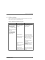
6.1
Introduction........................................................................................................... 6−1
6.2
System Power-on Problems ................................................................................... 6−2
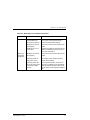
6.3
SCSI Device Problems .......................................................................................... 6−3
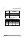
6.4
Boot Sequence Problems ....................................................................................... 6−4
A EEROM Parameter Settings
A.1
EEROM Parameter Settings..................................................................................A–1
Figures
2–1
Host Adapter and FAST-10 StorageWorks Shelf................................................... 2–4
2–2
Host Adapter and Ultra SCSI StorageWorks Shelf ................................................ 2–5
3–1
KZPBA–CA Single-ended Host Adapter............................................................... 3–3
3–2
Installing the KZPBA–CA Host Adapter............................................................... 3–4
3–3
Installing the 68-pin Cable Connector onto the Host Adapter................................ 3–6
3–4
Installing the 50-pin Cable Connector onto the Host Adapter................................ 3–6
3–5
Connecting Ribbon Cable to Internal SCSI Device ............................................... 3–7
3–6
Connecting Ribbon Cable to Second Internal SCSI Device ................................... 3–8
3–7
Connecting External SCSI Cable to Host Adapter................................................. 3–9
3–8
Connecting External SCSI Cable to External SCSI Device.................................... 3–9
3–9
Single Internal SCSI Bus .................................................................................... 3–11
3–10
Two Internal SCSI Buses ................................................................................... 3–12
3–11
External SCSI Bus ............................................................................................. 3–13
4–1
The ARC Console Screen ..................................................................................... 4–2
4–2
The Select ISP1020/1040 Screen .......................................................................... 4–3
4–3
The EEROM Configuration Utility 1020 Main Menu............................................ 4–5
4–4
The EEROM Configuration Utility 1040 Main Menu............................................ 4–5
4−5
The Edit EEROM Host Adapter Parameters Screen .............................................. 4 −7
4–6
Edit EEROM Device Parameters Screen ............................................................... 4–9
5−1
QLogic Fast! Util Main Menu .............................................................................. 5−2
5−2
The Configuration Settings Menu ......................................................................... 5 −3
5−3
Host Adapter Settings........................................................................................... 5−4
5−4
SCSI Device Settings ........................................................................................... 5−6
EK–KZPBA–UG. B01
v
KZPBA–CA PCI-to-UltraSCSI Host Adapter
Tables
vi
1–1
KZPBA–CA Specifications.................................................................................... 1–4
4–1
Default FIFO Threshold for Various Chips ........................................................... 4−8
5−1
QLogic “Fast!Util” Main Menu Options............................................................... 5−2
5−2
Host Adapter Settings........................................................................................... 5−5
5−3
SCSI Device Settings ........................................................................................... 5−7
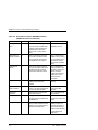
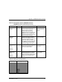
6–1
Power-on Problems Troubleshooting Table........................................................... 6–2
6–2
SCSI Device Troubleshooting Table ..................................................................... 6–3
6–3
Boot Sequence Troubleshooting Table.................................................................. 6–5
A–1
Descriptions of Host Adapter Parameters (KZPBA–CA General Operation) .........A–2
A–2
FIFO Threshold Controls and Corresponding Parameter Setting ...........................A–5
A–3
Asynchronous Data Setup Time ............................................................................A–5
A–4
Descriptions of Device EEROM Parameters (KZPBA–CA-to-Device Interaction) A–6
A–5
Selection Time-out Values....................................................................................A–7
EK–KZPBA–UG. B01
Revision Record
This Revision Record provides a concise publication history of this guide. It lists the
guide revision levels, release dates, and reasons for the revisions. It also describes how
the changes to affected pages are marked in the guide.
The following revision history lists all revisions of this publication and their effective
dates. The publication part number is included in the Revision Level column, with the
last entry denoting the latest revision. This publication supports the KZPBA–CA PCIto-Ultra SCSI Storage Adapter.
Revision Level
EK–KZPBA–UG. A01
EK–KZPBA–UG. B01
EK–KZPBA–UG. B01
Date
May 1997
May 1998
Summary of Changes
Original release
Changes formatting to
meet specifications;
changes EEROM
Configuration
Utility (Section 4.2).
vii
About This Guide
This chapter tells you what this User’s Guide does, identifies the audience, describes the
structure and contents (chapter-by-chapter), lists the conventions used in the guide, and
tells you how to get support and services from DIGITAL.
Introduction
This guide describes how to install and configure the KZPBA–CA PCI-to-Ultra
SCSI Host Adapter, and how to use the software utilities to modify the
parameters in the flash EEROM located on the module.
Visit our Web Site for the Latest Information
Check out our web site for the latest drivers, technical tips, and documentation.
We can be found in the technical area of our web page:
http://www.storage.digital.com/
Audience
This guide is intended for the end-user who is installing the KZPBA–CA Host
Adapter into a host computer.
Related Documentation
The user should be familiar with the documentation for the host computer and for
the SCSI devices that are mounted internally or externally and are to be
connected to the module.
Organization
This guide contains the following:
•
Chapter 1: Overview — Provides an overview of the KZPBA–CA PCI-toUltra SCSI Host Adapter. The KZPBA–CA is an ultra wide single-ended
host adapter.
•
Chapter 2: Configuration Guidelines — Provides information about valid
configurations, cables and adapters, a description of single-ended SCSI, and
sample configurations.
EK–KZPBA–UG. B01
ix
KZPBA–CA PCI–to–UltraSCSI Host Adapter
•
Chapter 3: Installing the KZPBA–CA PCI-to-Ultra SCSI Host Adapter —
Describes how to install the KZPBA–CA board into a computer. The
procedures include terminating the SCSI bus, verifying the installation, and
connecting the board to internal and external SCSI devices.
•
Chapter 4: EEROM Configuration Utility (Alpha-Systems) — Describes
how to use the supplied configuration utilities to modify parameters that are
stored in the board’s flash EEROM for Alpha-based systems.
•
Chapter 5: QLogic “Fast!Util” (Intel-Systems) — Describes how to use the
supplied configuration utilities to modify parameters that are stored in the
board’s flash EEROM for Intel-based systems.
•
Chapter 6: Troubleshooting — Provides troubleshooting information to
help diagnose problems that can occur during the installation of the
KZPBA–CA adapter.
•
Appendix A: EEROM Parameter Settings (Alpha-Systems) –– Describes
EEROM device-specific parameters on the KZPBA–CA for Alpha-based
systems. It provides a description of each parameter, its default setting, and
options available.
Conventions
The following conventions are used in this guide:
x
Convention Example
Description
Boldface type
For user input.
italic type
For document titles, utility titles, screen names,
and file names.
Plain monospace
type
For screen text.
EK–KZPBA–UG. B01
About This Guide
Support and Services
Who to contact in the Americas
Information and Product Questions:
Local Sales Office / StorageWorks Hotline
1-800-786-7967
Installation Support:
Contact the DIGITAL Distributor where the
Storage Solution was Purchased / Local
Digital Sales Office.
DIGITAL Multivendor Customer Service (MCS)
Installation
Contact the DIGITAL Customer Support
Center (CSC).
Warranty
Contact the DIGITAL Customer Support
Center (CSC) for warranty service after
solution is installed and operating.
Remedial
Contact the DIGITAL Customer Support
Center (CSC)
Note: A Service Contract is recommended
when the equipment is out of warranty.
Contact the local DIGITAL Sales Office.
Customer Support Center (CSC)
1 800-354-9000
Who to contact in Europe
Information and Product Questions,
Installation Support, and Installation:
For Warranty Service
For Remedial Service
Contact the DIGITAL Distributor or reseller
from whom the Storage Solution was
purchased.
See the Warranty Card packaged with the
product.
Contact the DIGITAL Distributor or reseller
from whom the Storage Solution was
purchased.
Note: A Service Contract is recommended
when the equipment is out of warranty.
Who to contact in Asia Pacific
For all services, contact the DIGITAL Distributor or reseller from whom the
equipment was purchased.
EK–KZPBA–UG. B01
xi
1
Overview
This chapter provides an overview of the KZPBA–CA PCI-to-Ultra SCSI Host Adapter.
The KZPBA–CA is an ultra wide single-ended host adapter.
1.1
Introduction
The KZPBA–CA host adapter module provides the interface between the host
computer’s PCI bus and internal and/or external SCSI devices. The KZPBA–CA
combines a powerful Reduced Instruction Set Computing (RISC) processor, a
SCSI executive processor, and a PCI local bus interface on a single chip.
The KZPBA–CA is a leading edge host adapter that supports bootable devices
and provides a powerful multi-tasking interface. The SCSI bus can be connected
to disk drives, CD-ROM drives, scanners, tape drives, and other SCSI devices.
More than one KZPBA–CA host adapter can be installed in the same host
computer. Each host adapter and its associated SCSI devices form a separate
SCSI bus.
The RISC processor minimizes the overhead of the host computer’s
microprocessor by transferring data directly into the host computer’s memory. It
also manages the actual data transfers between the host computer and the SCSI
devices without involving the host computer’s microprocessor.
The SCSI processor negotiates with each device on the SCSI bus to establish the
data transfer rate between the host adapter and each SCSI device. It also
automates SCSI command processing and significantly reduces the number of
interrupts and command overhead.
The KZPBA–CA is capable of 32-bit bus master data transfers, including PCI
enhanced data transfer commands. The host adapter supports all SCSI-2 and
SCSI-3 functions.
EK–KZPBA–UG. B01
1–1
KZPBA–CA PCI-to-UltraSCSI Host Adapter
The host adapter supports multithreaded I/O operations, thereby allowing
simultaneous operations on multiple SCSI targets or Logical Units (LUNs). In
systems with multiple targets, the Disconnect/Reconnect feature optimizes SCSI
bus usage. In systems that have fragmented memory buffers, the Scatter/Gather
feature provides high performance.
The KZPBA–CA comes with both AXP and Intel configuration utilities. These
configuration utilities provide the capability of changing settings on the board
flash EEROM without having to make physical changes to the host adapter
board. You can change settings such as host adapter SCSI termination and SCSI
Parity Checking.
1.2
KZPBA–CA Ultra Wide Single-Ended Host Adapter
The Ultra Wide Single-ended Host Adapter contains two 68-pin high density
connectors, one internally on the surface of the board and the other on the
external bulkhead, and one 50-pin connector. The internal connectors are used to
connect any internal SCSI drives to the PCI bus. The KZPBA–CA single-ended
Host Adapter is shown in Figure 3–1.
In a 16-bit (wide) SCSI bus, the KZPBA–CA can directly support up to 15 wide
single-ended SCSI devices (operating system dependent). Each of the two 68-pin
connectors can support up to 15 single-ended 16-bit SCSI devices or seven
single-ended 8-bit SCSI devices. The 50-pin connector can support up to seven
single-ended 8-bit devices.
You can use only internal or external SCSI connectors at any one time. The
KZPBA–CA does not support simultaneous use of both internal and external
connectors.
1.3
Major Features of the KZPBA–CA
•
•
•
•
•
•
•
•
1–2
Compliance with PCI Local Bus Specification Revision 2.0, ANSI X3.131
SCSI-2 Standard, ANSI X3T10/1071D SCSI-3 Fast 20 Standard, and U.S. and
international safety/emissions standards
Ultra-Narrow SCSI (8-bit, 20 MB per second, 7 devices)
Ultra-Wide SCSI (16-bit, 40 MB per second, 15 devices)
Single-ended version
Ability to boot from any drive on the SCSI bus
Onboard flash EEROM that can be customized using a configuration utility –
no need to remove the computer cover to change configuration
A wide variety of operating system specific managers and device module
software
Extensive support for DIGITAL StorageWorks storage products
EK–KZPBA–UG. B01
Chapter 1. Overview
PCI Bus Interface
• Up to 132 MB/sec data transfer rate on the PCI bus
• PCI single and dual address cycles support
• PCI bus address and data parity generation
• PCI bus master for data transfer
SCSI-3 Implementation
•
•
•
•
•
•
•
•
•
•
•
•
Concurrent support for asynchronous, Fast SCSI synchronous, and Ultra SCSI
synchronous devices
Concurrent support for 8- and 16-bit SCSI devices
Scatter/Gather
Disconnect/Reconnect
Fully multithreading/multitasking
68-pin high density external connector
One 68-pin high density and one 50-pin internal connectors
Tagged Queuing
Support of multiple LUNs
SCSI termination power control
Parity handling in Data, Message, Status, Selection/Reselection, and
Command phases
Active negation
Maximum Off-loading of Host CPU Requirements
•
•
•
•
Onboard RISC and SCSI executive processors automates SCSI processing
Low SCSI processing overhead
Bus Master DMA implementation
Task scheduling and message-based communication
EK–KZPBA–UG. B01
1–3
KZPBA–CA PCI-to-UltraSCSI Host Adapter
1.4
Support and Information Services
The KZPBA–CA Host Adapter is designed for easy installation and use. If you
need further assistance, please contact your DIGITAL services representative.
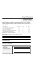
Specifications for the KZPBA–CA are listed in Table 1–1.
Table 1–1 KZPBA–CA Specifications
Item
Operating Power
Specification
5 volts @ 1 Ampere
Performance
Interface transfer rate:
Synchronous Ultra Wide SCSI
Synchronous Ultra SCSI
Synchronous Fast Wide SCSI
Synchronous Fast SCSI
Synchronous SCSI
Asynchronous SCSI
Host Data Transfer Rate:
40 MB/sec
20 MB/sec
20 MB/sec
10 MB/sec
5 MB/sec
5 MB/sec
32-bit bus master DMA data transfers
up to 132 MB/sec
Environmental
Operating Temperature:
Operating Relative Humidity:
0°C/32°F to 55°C/131°F
10% to 90%, non-condensing
Storage Temperature:
Storage Relative Humidity:
-20°C/-4°F to 70°C/158°F
5% to 95%, non-condensing
Physical
Form Factor
17.78 cm X 10.67 cm (7.0" X 4.2")
CPU
On-chip RISC processor
RAM
64 Kbytes of static RAM
Connectors:
Ultra Wide Single-Ended
Safety and EMI Compliances
1–4
68-pin, high-density, external
68-pin, high-density, internal
50-pin, ribbon, internal
FCC Class B, Vfg, CE
EK–KZPBA–UG. B01
2
Configuration Guidelines
Before you install the KZPBA–CA host adapter in your computer, you need to become
familiar with the product, the configuration guidelines for the host adapter, and its SCSI
bus. This chapter includes installation guidelines, a description of single-ended SCSI
buses, and sample configurations.
NOTE
If you are familiar with configuration guidelines
and know the configuration that you are installing,
skip to Chapter 3 and begin by installing the host
adapter.
2.1
Configuration Guidelines
More than one KZPBA–CA Host Adapter can be installed in the same host
computer. The number of boards that can be installed is only limited by the
number of PCI slots available in the host computer. Unless a SCSI-bus converter
is used, only single-ended SCSI devices can be directly connected to the singleended host adapter. For external UltraSCSI device use, refer to Section 2.5 and to
the UltraSCSI Configuration Guidelines (EK–ULTRA–CG) for recommended
configurations; also, refer to our Web page at: http://www.storage.digital.com/.
Physical Configuration
The Personality Module resides in the BA356 storage shelf. The host adapter
connects directly to the Personality Module using a point-to point cable
connection.
Single-Ended SCSI Bus Configuration
The DS–BA356–XX storage shelf contains two single-ended SCSI buses that are
internally configured as a single bus. A maximum of seven 3½-inch half-height
8-bit or 16-bit SCSI devices in DIGITAL StorageWorks Building Blocks (SBBs)
can be attached to the bus. This bus can be split so that storage shelf can be
configured to have one 3-device bus configuration and one 4-device bus
configuration. This is useful when a specific device requires more than one slot
(such as a tape loader or solid state drive).
EK–KZPBA–UG. B01
2–1
KZPBA–CA PCI-to-UltraSCSI Host Adapter
SCSI ID Selection
The KZPBA–CA host adapter is assigned SCSI ID 7. For the SCSI devices
mounted in the storage shelf, the device address is determined by its physical
location in the storage shelf, with the slot number equating to the SCSI ID
number.
SCSI Bus Termination
For a single-ended bus connection, the single-ended bus is terminated at one end
by the KZPBA–CA adapter and at the other end by the StorageWork shelf
Personality Module
2.2
Configuration Topography
You can configure the host adapter to be in the middle or at the end of the SCSI
bus.
Configure the host adapter in the middle of the SCSI bus by using both internal
connectors, each connected to one or more internal SCSI devices.
When the host adapter is at one end of the bus, the bus is terminated at the host
adapter and at the last SCSI device. When the host adapter is in the middle of the
bus, the bus is terminated by the last SCSI device at each end of the bus.
2.2.1 SCSI Cable Selection
Always select high-quality SCSI cables to use in your system. Because singleended host adapters support UltraSCSI transfer rates, the use of high-quality
cabling is especially critical. Cables of a lesser quality can cause data corruption,
parity errors, and other problems.
Round external SCSI cables vary widely in quality and electrical characteristics.
Ascertain, from your cable supplier, that external cables meet SCSI-2 standards.
The following are some cable selection guidelines:
•
Use layered twisted pair cables with 25-wire pairs
•
Use cables that have a single-ended impedance range of 80-100ohms
•
Do not use cables shorter than 30 cm (11.8 inches) between any two SCSI
devices
2.2.2 SCSI Bus Lengths
The length of a SCSI bus segment is the cable distance between the two bus
terminators, with each terminator located at an end of the bus segment. The
length of the Single-ended SCSI bus should not exceed 1.5 meters when
operating in UltraSCSI mode, using internal connectors to internal devices. If
you are using an UltraSCSI DIGITAL StorageWorks enclosure, refer to the
2–2
EK–KZPBA–UG. B01
Chapter 2. Configuration Guidelines
UltraSCSI Configuration Guidelines for cable lengths. For Fast-10 SCSI
configurations with BA356 StorageWorks enclosures, the maximum cable length
is 2.0 meters.
2.3
SCSI Bus Termination
The integrity of the data written to or read from a SCSI device can be seriously
compromised due to signal reflections caused by an unbalanced SCSI bus. An
unbalanced bus is the result of an improperly terminated or unterminated bus.
Therefore, failure to terminate the bus properly can result in a system crash or
even worse, data corruption.
A balanced bus is achieved by properly installing bus terminators on the SCSI
bus in relation to the host adapter and the SCSI devices. SCSI bus termination
on the KZPBA–CA Host Adapter ultra wide single-ended board is established
using one of the utility programs included in the host adapter kit.
Proper bus termination involves supplying termination power onto the SCSI bus
and the strategic placement of terminators on the bus. The KZPBA–CA PCI-toUltraSCSI Host Adapter provides active termination power and is generally the
only source of termination power required on the bus. However, Digital
Equipment Corporation recommends that all devices on the SCSI bus supply
termination power to ensure that there is a sufficient level of power along the
entire bus. SCSI devices are protected by a diode or similar semiconductor to
prevent back flow of the termination power when more than one device supplies
this power.
2.4
FAST-10 SCSI Configuration Example
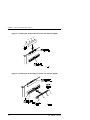
Figure 2–1 shows a configuration topography that you can use for the
KZPBA–CA connected to a Fast-10 DS–BA356–XX StorageWorks shelf.
EK–KZPBA–UG. B01
2–3
KZPBA–CA PCI-to-UltraSCSI Host Adapter
Figure 2–1 Host Adapter and FAST-10 StorageWorks Shelf
NOTE
Maximum cable length is 2 meters
2–4
EK–KZPBA–UG. B01
Chapter 2. Configuration Guidelines
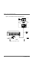
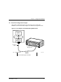
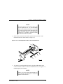
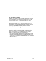
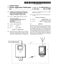
2.5 UltraSCSI Configuration Example
This sample configuration (Figure 2-2) shows how you can connect the
KZPBA–CA PCI-to-SCSI Host Adapter to an UltraSCSI StorageWorks shelf.
Figure 2–2 Host Adapter and UltraSCSI StorageWorks Shelf
H ost C om pu te r
S ystem
M od ule
P C I B us
KZPBA
S in gle-E nd ed
A d a pte r ID 7
B N 3 8C -X X
C a ble
D S -B A 35 6 -X X
S to rag e S he lf
X X = Le ng th in M eters
S H R -1 0 6 1
NOTE
Maximum cable length is 20 meters.
EK–KZPBA–UG. B01
2–5
3
Installing the KZPBA–CA Adapter
This chapter describes how to install the KZPBA–CA board into a computer. The
procedures include terminating the SCSI bus, verifying and troubleshooting the
installation, and connecting the board to internal and external SCSI devices.
3.1
Installation Overview
The installation of the KZPBA–CA includes the following steps:
•
Installing the host adapter module into your computer
•
Modifying the contents of the flash EEROM as necessary
•
Loading the appropriate software drivers for the operating system running on
your computer
•
Connecting internal or external SCSI devices to the module
These procedures take approximately 30 minutes to complete.
3.2
Getting Started
Prior to starting the installation, do the following:
•
Check that you have the necessary user-supplied hardware and software
•
Inventory the contents of the KZPBA–CA Host Adapter Kit
•
Back up the computer system
EK–KZPBA–UG. B01
3–1
KZPBA–CA PCI-to-UltraSCSI Host Adaptaer
3.2.1 User-Supplied Hardware and Software Requirements
The KZPBA–CA PCI-to-UltraSCSI Host Adapter requires the following usersupplied hardware and software:
•
An AXP- or Intel-based computer system with a PCI local bus, a 3½-inch
(1.44 MB) floppy drive, an available PCI slot, disk space to load software
drivers, and the associated system hardware manual
•
The SCSI cables necessary to connect SCSI devices to the adapter module
•
One of the following operating systems (refer to the release notes for specific
supported operating system versions):
-
Windows NT
-
DIGITAL OpenVMS
-
DIGITAL UNIX
3.2.2 KZPBA–CA Host Adapter Kit Contents
The KZPBA–CA Host Adapter kit contains the following:
•
KZPBA–CX PCI-to-UltraSCSI Host Adapter module
•
License Agreement
•
One diskette containing the AXP flash EEROM Configuration Utility and
operating system specific software drivers for both AXP and Intel Windows
NT based systems
•
This guide
•
Release Notes
Contact your Service Representative if any items are missing.
3.2.3 Back up Your System
Follow your normal procedures to back up your system before installing the
KZPBA–CA host adapter.
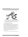
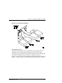
3.3
Installing the Host Adapter
Install the host adapter module using the following procedure. Take precautions
to protect the module from static discharge. The single-ended Host Adapter is
shown in Figure 3–1.
3–2
EK–KZPBA–UG. B01
Chapter 3. Installing the KZPBA–CA Adapter
Figure 3–1 KZPBA–CA Single-Ended Host Adapter
CAUTION
To protect the board from static discharge, wear
an electrostatic discharge (ESD) wrist strap. If a
wrist strap is unavailable, ground yourself by
touching a bare metal surface on the computer
chassis before you open the case.
1.
Turn off the power to the computer system and attached peripherals.
Disconnect the power cords.
2.
Remove the computer cover.
3.
Locate an available PCI bus slot. PCI slots are shorter than ISA and EISA
slots and are normally colored white. (Refer to your system hardware
manual to determine the location of the PCI bus slot in your system.)
Unscrew and remove the outside slot cover. The slot cover is the metal strip
that covers the opening in the rear of the computer chassis and where the
external connector on the adapter fits (save the screw.)
4.
Carefully remove the KZPBA–CA PCI-to-UltraSCSI host adapter from its
protective anti-static bag and insert it into the slot. Press down on the top of
the card until it seats firmly. See Figure 3–2.
EK–KZPBA–UG. B01
3–3
KZPBA–CA PCI-to-UltraSCSI Host Adaptaer
NOTE
PCI cards are designed with their components on
the opposite side of non-PCI cards
5.
Secure the KZPBA–CA host adapter with the screw previously used to
secure the slot cover.
6.
Do not install the computer cover or reconnect power until all the SCSI
devices are connected.
Figure 3–2 Installing the KZPBA–CA Host Adapter
3–4
EK–KZPBA–UG. B01
Chapter 3. Installing the KZPBA–CA Adapter
3.3.1 Connecting Internal SCSI Devices
Refer to your SCSI device documentation if you want to install one or more
SCSI device inside the host computer. The internal device(s) must be singleended.
To connect an internal SCSI device to the KZPBA–CA host adapter, you will
need one, or both, of the following cables depending on the requirements of your
internal drive.
•
A 50-pin connector SCSI ribbon cable with a 50-pin header internal connector
to mate with the KZPBA–CA host adapter 50-pin connector
•
A 68-pin connector SCSI cable with a 68-pin header internal connector to
mate with the KZPBA–CA host adapter 68-pin connector
NOTE
If you are connecting more than one internal SCSI
drive to the KZPBA–CA host adapter, there must
be additional connectors on the cable to
accommodate the additional drives.
Follow these steps to install the internal SCSI ribbon cable:
1.
Insert the connector on one end of the SCSI cable into the connector on the
host adapter (see Figures 3–3 and 3–4).
EK–KZPBA–UG. B01
3–5
KZPBA–CA PCI-to-UltraSCSI Host Adaptaer
Figure 3–3 Installing the 68-pin Cable Connector Onto the Host Adapter
Figure 3–4 Installing the 50-pin Cable Connector Onto the Host Adapter
3–6
EK–KZPBA–UG. B01
Chapter 3. Installing the KZPBA–CA Adapter
NOTE
The colored stripe on one side of the ribbon cable
must be aligned with pin 1 on the host adapter
board. For all remaining connections on the SCSI
bus, make sure that the colored stripe edge of the
ribbon cable aligns with pin 1 on the SCSI device
connector. Pin 1 orientation is required so that all
the SCSI devices will work properly.
2.
Insert the last connector on the ribbon cable into the connector on the
internal SCSI device on the shelf (see Figure 3–5).
Figure 3–5 Connecting Ribbon Cable to Internal SCSI Device
3.
To connect a second internal SCSI device, plug the middle ribbon cable
connector into the connector on the second internal device (see Figure 3–6)
maintaining the pin orientation.
NOTE
Refer to your host computer documentation for
more information describing how to connect the
adapter to internal devices.
EK–KZPBA–UG. B01
3–7
KZPBA–CA PCI-to-UltraSCSI Host Adaptaer
Figure 3–6 Connecting Ribbon Cable to a Second Internal SCSI Device
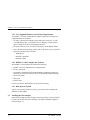
4.
To connect three or more internal SCSI devices to the SCSI bus, the ribbon
cable must have enough connectors to accommodate all the devices. Plug the
connectors into the SCSI devices maintaining the pin-1 orientation.
5.
If you are using both internal connectors on the host adapter, proceed in the
same fashion as above for the other cable.
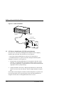
3.3.2 Connecting External SCSI Devices
The preferred cabling method is a point-to-point cable connection from the
KZPBA–CA Host Adapter to the DS–BA356–XX. Up to fifteen wide SCSI
devices can be supported externally to the KZPBA–CA through carefully cabled
topologies. See the UltraSCSI Configuration Guide for more details.
The KZPBA–CA does not support daisy-chained configurations with the
KZPBA–CA in the middle of the SCSI bus attached by the external connector.
The external connector on the single-ended version of the module is a 68-pin
connector. The external connector is keyed so that it can be plugged in only one
way making the pin-1 orientation automatically correct.
Follow these steps to connect an external SCSI device housed within a
DS–BA356–XX shelf:
1.
3–8
Attach one end of the cable to the KZPBA–CA host adapter (see Figure 3-7).
EK–KZPBA–UG. B01
Chapter 3. Installing the KZPBA–CA Adapter
Figure 3–7 Connecting External SCSI Cable to Host Adapter
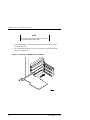
2.
Attach the other end of the cable to the connector on the personality module
in the DS–BA356–XX wide SCSI storage shelf (see Figure 3–8).
EK–KZPBA–UG. B01
3–9
KZPBA–CA PCI-to-UltraSCSI Host Adaptaer
Figure 3–8 Connecting External SCSI Cable to External SCSI Device
E xtern al
S C S I D evice s
E xterna l
S C S I C ab le s
3.4
P erson a lity
M od u le
S H R -10 6 0
Setting SCSI Bus Termination
A set of terminating resistors must be either physically installed or software
enabled on the first and last physical device on the SCSI bus. You may have to
change the termination on the host adapter module and on some of the SCSI
devices.
1.
Determine which two SCSI devices (including the host adapter) are at each
end of the SCSI bus. Install or enable termination on these two devices.
2.
Disable termination on all other devices on the SCSI bus.
3.
If one 8-bit and one 16-bit connector are used in a single-ended SCSI bus
application, the upper 8 bits of the default termination setting must be
terminated using the flash EEROM Configuration Utility (see Chapter 4).
The following paragraphs contain more information about device termination.
3.4.1 SCSI Device Termination
Refer to the SCSI device manufacturer’s documentation to determine how a
particular device’s termination is enabled or disabled.
3–10
EK–KZPBA–UG. B01
Chapter 3. Installing the KZPBA–CA Adapter
3.4.2 Host Adapter Termination
Termination on the KZPBA–CA single-ended host adapter module is software
controlled and its default is auto enabled. If you are using only one internal
connector or external connector, the default does not have to be changed.
Single-Ended Module
On the single-ended module, if you are using both internal connectors, the
default termination must be changed. To do this, first complete the installation,
then refer to the flash EEROM Configuration Utility (see Chapter 4).
3.4.3 Possible Termination Configurations
Internal Devices only
Internal devices can only be used with the KZPBA–CA Single-ended Host
Adapter. How you terminate the devices and the host adapter depends on
whether one or both of the module-edge connectors are used.
•
If only one of the board-edge connectors is used, you must terminate the last
internal device on the SCSI bus and disable termination on the other devices.
The host adapter is already terminated by default and this setting should not be
changed (see Figure 3–9).
EK–KZPBA–UG. B01
3–11
KZPBA–CA PCI-to-UltraSCSI Host Adaptaer
Figure 3–9 Single Internal SCSI Bus
CAUTION
A KZPBA–CA host adapter does not support the
simultaneous use of both internal and external
connectors. If it is necessary to attach both
internal and external SCSI devices, a second
KZPBA–CA Host Adapter can be installed in the
same host computer.
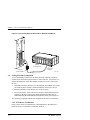
•
3–12
If you attach internal SCSI devices to both of the internal connectors on the
host adapter, you must terminate the last SCSI device on each internal cable
and disable termination on the other devices (see Figure 3–10). Because one
device is attached to the 8-bit, 50-pin connector and the other attached to the
16-bit, 68-pin connector, the host adapter termination must be changed so
that the high order bits are on. This is necessary to maintain the balance in
the SCSI bus. To do this refer to the flash EEROM Configuration Utility
(refer to Chapter 4).
EK–KZPBA–UG. B01
Chapter 3. Installing the KZPBA–CA Adapter
Figure 3–10 Two Internal SCSI Buses
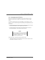
External Devices Only
When only external SCSI devices are connected to the host adapter, the last
external device must be terminated and all other devices must have their
termination removed. DIGITAL StorageWorks simplifies this by terminating the
end of the bus within the storage enclosure. For example, as shown in
Figure 3-11, the end of the bus is terminated by the Personality Module. The host
adapter is already terminated by default and this setting should not be changed.
EK–KZPBA–UG. B01
3–13
KZPBA–CA PCI-to-UltraSCSI Host Adaptaer
Figure 3–11 External SCSI Bus
Term ination
E nabled
Pers onality
M odule
Hos t A dapter
Ternm ination Enabled
K ZPB A -13
S H R -1 05 9
3.5
SCSI Device Identification (SCSI ID) and Arbitration
Every device on a SCSI bus, including the Host Adapter, must be uniquely
identified with a SCSI ID. The SCSI ID serves two purposes:
•
It provides a unique identification to each device on the SCSI bus
•
It establishes the device’s priority on the bus during the arbitration phase
Setting the SCSI ID is a two-step process:
1.
Determine the SCSI ID number that is to be assigned to each drive on the
SCSI bus. To set the ID for the various devices that are going to be on the
bus, read the manufacturer’s documentation for each device to determine the
appropriate switch or jumper settings.
2.
Change SCSI IDs as necessary so that priority arbitration is as desired and
that no two devices have the same ID. The host adapter should be assigned
ID 7.
If more than one host adapter is installed, each host adapter has a separate SCSI
bus associated with it. The second SCSI bus can use the same ID numbers as
assigned to the first bus even though different devices are used.
3–14
EK–KZPBA–UG. B01
Chapter 3. Installing the KZPBA–CA Adapter
SCSI Bus Priority Arbitration
SCSI bus priority arbitration is based on the SCSI ID of the arbitrating device.
Priority arbitration is established from highest to lowest. The host adapter is
normally assigned SCSI ID 7.
For example, in the following priority arbitration scheme, SCSI ID 7 has the
highest priority and SCSI ID 8 has the lowest priority:
SCSI ID 7-6-5-3-2-1-0-15-14-13-11-9-8
3.6
Installing Operating System Drivers
To install drivers, see the Driver.txt file on the driver floppy diskette for your
operating system. This floppy diskette comes with the product kit.
3.7
Verifying Installation on Systems with Windows NT
To verify installation on AXP-Based systems, see section 3.7.1.
To verify installation on Intel-systems, see section 3.7.2.
3.7.1 Verifying Installation on AXP-Based Systems
If you are using the Windows NT operating system on an AXP-based system,
verify the proper installation of the KZPBA–CA as follows:
1.
Power up your system; the Alpha AXP should go through its start up
sequence and then display the ARC Boot Menu on your display terminal.
Typically, your display should look like the following:
Alpha Firmware Version 4.52
Copyright (c) 1993-1996 Microsoft Corporation
Copyright (c) 1993-1996 Digital Equipment Corporation
Boot Menu
Boot Windows NT
Boot an alternate operating system
Run a program
Supplementary menu ...
Use the arrow keys to select, then press Enter
EK–KZPBA–UG. B01
3–15
KZPBA–CA PCI-to-UltraSCSI Host Adaptaer
If you do not see this menu, refer to your system documentation for more
information about initially setting up your Alpha AXP. Return to this procedure
when you have the Boot Menu displayed.
2.
From the Boot Menu, select the Supplementary Menu item.
3.
Next, select the Display Hardware Configuration item. The system will now
display several pages of information about your Alpha AXP system.
4.
Press the Return or Enter key to verify the devices detected and
supported by the software. Your screen should look similar to the following
depending upon the devices detected and supported.
ARC
Devices detected and supported by the firmware:
eisa(0)video(0)monitor(0)
multi(0)key(0)Keyboard(0)
eisa(0)disk(0)fdisk(0)
(Removable)
multi(0)serial(0)
multi(0)serial(1)
scsi(0)disk(3)rddisk(0) (RAW)
DEC RZ28
(C) DECX442
scsi(0)cdrom(4)fdisk(0) (Removable)
DEC RRD43
(C) DEC0064
scsi(1)disk(1)rdisk(0)
DEC RZ28
(C) DECX442
DEC RZ28M
(C) DEC0446
scsi(1)disk(2)rdisk(0)
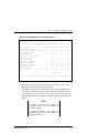
5.
3–16
(RAW)
(RAW)
Press the Return or Enter key to move through the pages until your
screen has the PCI Slot Information display. Your screen should look similar
to the following example:
EK–KZPBA–UG. B01
Chapter 3. Installing the KZPBA–CA Adapter
PCI slot information
Bus
Device
Number
Function
Number
Vendor
ID
Device
ID
Revision
ID
Interrupt
Vector
Device
Type
0
8
0
1011
1
2
0
PCI
Bridge
0
10
0
8086
482
5
0
EISA
Bridge
0
11
0
1011
4
2
11
Video
Card
1
0
0
1011
2
24
21
Ethernet
1
1
0
0
1020
2
22
SCSI
1
2
0
0
1020
2
23
SCSI
6.
Note that the fifth row in the table contains a Vendor ID field of 0 and a
Device ID of 1020. These two values uniquely identify the KZPBA–CA.
Search your display for a line (or lines if you installed more than one
KZPBA–CA) containing these exact values. If there is no entry that
corresponds to the KZPBA–CA, your adapter may not be correctly installed.
Power off your system and repeat the installation process in Chapter 3.
7.
When you have found all the installed KZPBA–CA adapters listed in step 4,
continue to press Enter until you have returned to the Supplementary
Menu, then select the Boot Menu item to return to that menu.
EK–KZPBA–UG. B01
3–17
KZPBA–CA PCI-to-UltraSCSI Host Adaptaer
3.7.2
For Systems Running Alpha BIOS
If your system is running with an Alpha BIOS, verify the proper installation of
the KZPBA-CA as follows:
1.
Power up your system; after the Alpha AXP goes through its start-up
sequence the Alpha BIOS initialization screen should appear.
2.
Press F2 for setup.
3.
Select Display System Configuration… from the Alpha BIOS setup menu.
4.
Select Hard Disk Configuration from the Display System Configuration
menu and then press Enter. The system will now display the devices that
are attached to the Qlogic adapter.
5.
Press ESC to exit the Hard Disk Configuration menu.
6.
Select PCI Configuration to display the configuration of the Qlogic adapter.
7.
Select SCSI Device to list the installed Qlogic adapter.
8.
Press the ESC key repeatedly until you have returned to the Windows NT
operating system boot menu.
3.7.3 Verifying Installation on Intel-Based Systems
If you are using the Windows NT operating system on an Intel-based system,
verify the proper installation of the KZPBA–CA as follows:
1.
Turn on the power to your system.
2.
Verify proper installation of the KZPBA–CA during system boot. Look for a
BIOS initialization process message similar to the following:
QLogic Corporation
PCI SCSI ROM BIOS Version X.XX
Copyright © Qlogic Corporation 1993-97 All Rights Reserved
Press <Alt-Q> for Fast! Util
ISP Firmware X.XX
Using IRQ number X
Device Device Adapter SCSI
Number Type
Number ID
81
Disk
0
0
SCSI Vendor Product Product
LUN
ID
ID
Revision
0
XXX
XXX
XXXX
If no SCSI disk devices are attached to the computer, an error or status
message appears.
3–18
EK–KZPBA–UG. B01
Chapter 3. Installing the KZPBA–CA Adapter
3.8
3.
To further verify the installation, if desired, press the Alt-Q key
combination when the QLogic Ultra board BIOS initialization message
appears to start the QLogic Fast! Utility.
4.
The QLogic Fast! Utility displays the selected adapter in the top, left-hand
corner of the main menu. Select the Scan SCSI bus option from the Fast!
Util Options menu. See Chapter 5 for more details on using the QLogic Fast!
Utility.
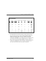
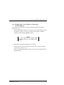
Verifying the Installation on AXP-Based Systems with DIGITAL
UNIX and DIGITAL OpenVMS
If you are using the DIGITAL UNIX (OSF/1) or DIGITAL OpenVMS operating
system, verify the proper installation of the KZPBA–CA as follows:
1.
Power up your system; the Alpha AXP should go through its start up
sequence and then enter the SRM console.
2.
Type: show config and press Return.
3.
Verify that the KZPBA–CA adapter is installed properly by observing the
listing in the configuration display for the "Qlogic ISP1020/1040" module.
The following is an example of a typical display for an AlphaServer 2100
system.
EK–KZPBA–UG. B01
3–19
KZPBA–CA PCI-to-UltraSCSI Host Adaptaer
Digital Equipment Corporation
AlphaServer 2100 4/200
SRM Console V4.0 – 3
Component
VMS PALcode X5.48-94, OSF PALcode X1.35-39
Status
Module ID
CPU 0
P
B2020-AA DECchip (tm) 21064-3
Memory 0
P
B2021-BA
I/O
64 MB
B2021-AA
dva0.0.0.0.1
Slot
RX26
Option
Hose 0, Bus 0, PCI
0
DECchip 21040-AA
ewa0.0.0.0.0.
08.00-2B-E2-82-34
1
NCR 53C810
pka0.7.0.1.0
SCSI Bus ID 7
dka200.2.0.1.0 RZ26
dka600.6.0.1.0 RRD43
2
Intel 82375EB
Bridge to Hose 1, EISA
6
Qlogic ISP1020/1040
pkb0.7.0.6.0
SCSI Bus ID 7
dkb100.1.0.6.0 RZ28
dkb400.4.0.6.0 RZ28M
3–20
EK–KZPBA–UG. B01
4
EEROM Configuration Utility (Alpha-Systems)
This chapter describes the EEROM configuration utility for the KZPBA-CA adapter in
Alpha- systems.
4.1
EEROM Parameter Settings
The KZPBA-CA host adapter ships with factory default EEROM parameters that
determine how the host adapter board operates and interacts with connected
devices. The default EEROM parameter settings were chosen to provide the best
performance optimization for most system configurations. If you want to change
the parameter settings, refer to Appendix B at the end of this guide.
The KZPBA-CA host adapter also ships with a floppy diskette containing the
ISP1020/1040 EEROM Configuration Utility for Alpha AXP which you can use
to change parameter settings. A description of the EEROM configuration utility
and how to use it to change parameter settings is presented in the following
section.
4.2
The EEROM Configuration Utility
The ISP1020/1040 EEROM Configuration Utility for Alpha AXP provides you
with a means to access and change the host specific and device specific
parameters stored in EEROM on the KZPBA-CA host adapter. It runs from the
ARC console of Alpha AXP systems (see the Release Note supplied with the
KZPBA-CA for the minimum version level required.)
The utility displays on a VGA monitor
The major steps required to change EEROM settings include:
•
Setting terminal, if displaying on a terminal
•
Starting the utility
•
Changing the appropriate host adapter or device-specific parameters
EK–KZPBA–UG. B01
4–1
KZPBA-CA PCI-to-UltraSCSI Host Adapter
4.2.1 Setting Terminal
To display the EEROM Configuration Utility on a VT320, or newer generation
terminal, set your terminal to: VT300 mode, 8 bit controls.
4.2.2 Starting the EEROM Configuration Utility
Starting the EEROM Configuration Utility varies depending upon whether your
system runs AlphaBIOS. For systems without AlphaBIOS go to section 4.2.2.1.
For systems with AlphaBIOS go to section 4.2.2.2.
4.2.2.1 Systems Without AlphaBIOS
For systems without AlphaBIOS, follow these steps to start the EEROM
Configuration Utility:
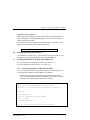
1. If your system runs Windows NT, it should power up to the ARC console.
The ARC console screen appears as shown in Figure 4–1.
If your system runs DIGITAL UNIX or DIGITAL OpenVMS, set the
os_type variable to NT by typing: set os_type NT, and reboot your
system.
Figure 4–1 The ARC Console Screen
Alpha Firmware Version 4.52
Copyright (c) 1993-1996 Microsoft Corporation
Copyright (c) 1993-1996 Digital Equipment Corporation
Boot Menu
Boot Windows NT
Boot an alternate operating system
Run a program
Supplementary menu ...
Use the arrow keys to select, then press Enter
4–2
2.
Insert the floppy diskette containing the eeromcfg.exe file into the
appropriate floppy drive.
3.
Use the up and down arrow keys to highlight the Run a Program option from
the Boot Menu on the ARC console and press Enter to select it. The
following prompt appears: Program to run:
EK–KZPBA–UG. B01
Chapter 4. EEROM Configuration Utility
4.
5.
Type either of the following at the prompt and press Enter:
To start from a floppy diskette, type:
a:eeromcfg
To start from a CD-ROM, type:
cd:\utility\eeromcfg
Press the Enter key. The ISP1020/1040 EEROM Configuration Utility
V2.1 screen appears similar to the one shown in Figure 4–2.
Figure 4–2 The Select ISP1020/1040 Screen
------------------------------------------------------------ISP1020/1040 EEROM Configuration Utility V2.1
------------------------------------------------------------+============Select ISP1020================+
| Bus
Virtual Slot
Address
|
| [0
12
B2021000]
|
|
__________________________________________ |
|
|
|
< (O) k >
< E(x)it >
|
|
|
+==========================================+
EK–KZPBA–UG. B01
4–3
KZPBA-CA PCI-to-UltraSCSI Host Adapter
4.2.2.2 Systems With AlphaBIOS
For systems with AlphaBIOS, follow these steps to start the EEROM
Configuration Utility:
1.
If your system runs Windows NT, go to Step 3; otherwise continue with
Step 2.
2.
If your system is running SRM console, set the os_type variable to NT by
typing: set os_type NT; then reboot your system.
NOTE
Remember to reset your system back to the SRM
after running the configuration utility. Here are the
steps to do:
•
Select CMOS Setup and press Enter.
•
In the CMOS Setup screen press F6; the
Advanced CMOS Setup screen is displayed.
•
Select DIGITAL UNIX (SRM) or DIGITAL
OpenVMS (SRM), and press F10.
•
The CMOS Setup screen is again displayed;
press F10 to save the change.
•
Reset the system.
3.
Press F2 for Setup. The AlphaBIOS Setup screen appears.
4.
Select Utilities from the AlphaBIOS Setup menu.
5.
Select Run Maintenance Program from the Utilities menu. The Run
Maintenance Program window appears.
6.
Type the following at Program Name: eeromcfg
Tab to Location: and use the arrow keys to select the correct location of the
program, either a: for floppy diskette or CD: for CD-ROM.
7.
4–4
Press the Enter key. The ISP1020/1040 EEROM Configuration Utility
V2.1 screen appears similar to the one shown in Figure 4–2.
EK–KZPBA–UG. B01
Chapter 4. EEROM Configuration Utility
4.3
Using the EEROM Configuration Utility
Use the up and down arrow keys to move the selector brackets [ ].
To begin, move the selector brackets to the ISP1020/1040 on the Select
ISP1020/1040 screen, shown in Figure 4−2, that you want to configure. The
Configure EEROM Parameters menu appears as shown in Figure 4–3 for ISP
1020 and in Figure 4−4 for ISP 1040.
Use the up and down arrow keys to move the bracket selector to an option on the
Configure EEROM Parameters menu (or type the letter of the option in
parentheses) and press Enter to select the option.
Figure 4–3 The EEROM Configuration Utility 1020 Main Menu
------------------------------------------------------------ISP1020/1040 EEROM Configuration Utility V2.1
------------------------------------------------------------+========Configure EEROM Parameters========+
|
|
| [ (L)oad Default EEROM Parameters
]
|
|
Edit EEROM (H)ost Adapter Parameters
|
|
Edit EEROM (D)evice Parameters
|
|
E(x)it
|
|
|
+==========================================+
Figure 4–4 The EEROM Configuration Utility 1040 Main Menu
------------------------------------------------------------ISP1020/1040 EEROM Configuration Utility V2.1
------------------------------------------------------------+========Configure EEROM Parameters========+
|
|
| [ (L)oad Default EEROM Parameters
]
|
|
Edit EEROM (H)ost Adapter Parameters
|
|
Edit EEROM (D)evice Parameters
|
|
Enable (U)ltra [FAST-20] on all devices
|
|
Enable [FAST-10] on all devices|
|
|
E(x)it
|
|
|
+==========================================+
EK–KZPBA–UG. B01
4–5
KZPBA-CA PCI-to-UltraSCSI Host Adapter
4.4
Changing EEROM Parameters
Tables A–1 and A–3 in Appendix A describe reasons to change the EEROM
parameters. This section describes how to change:
•
Host adapter parameter settings, which control the general operation of the
KZPBA-CA host adapter
and,
•
Device EEROM parameter settings, which control how the KZPBA-CA
interacts with connected devices.
4.4.1 Changing Host Adapter Parameters
To change host adapter parameters, follow these steps:
1.
Use the up and down arrow keys, or type “h” to move the bracket selector to
the Edit EEROM Host Adapter Parameters option on the Configure EEROM
Parameters menu and press Enter. The Edit EEROM Host Adapter
Parameters screen appears as shown in Figure 4–5.
Refer to Table A–1 in Appendix A for a list of the host adapter parameter default
settings, parameter descriptions, and optional parameter settings.
4–6
EK–KZPBA–UG. B01
Chapter 4. EEROM Configuration Utility
Figure 4–5 The Edit EEROM Host Adapter Parameters Screen
+================Edit EEROM Host Adapter Parameters=============
|
| Parameters
Default
New
|FIFO Threshold
3
[
0
]
|Host Adapter Enable
1
[
1
]
|Initiator SCSI ID
7
[
7
]
|Bus Reset Delay
1
[
1
]
|Retry Count
0
[
1
]
|Retry Delay
1
[
1
]
|Asynchronous Data Setup Time
9
[
9
]
|REQ/ACK Active Negation
1
[
1
]
|Data Line Active Negation
1
[
1
]
|Data DMA Burst Enable
1
[
1
]
|Command DMA Burst Enable
1
[
1
]
|Tag Aging
8
[
8
]
|Low Termination Enable
1
[
1
]
|High Termination Enable
1
[
1
]
|Selection Timeout
250
[ 250
]
|Maximum Queue Depth
256
[ 256
]
|FIFO 128 Threshold Enable
0
[
0
]
|Fast RAM Enable
1
[
1
]
|SCSI Reset Disable
0
[
0
]
|Enable Auto Termination
1
[
1
]
|
|
<(O)K>
<(C)ancel>
+===============================================================
+
|
|
|
|
|
|
|
|
|
|
|
|
|
|
|
|
|
|
|
|
|
|
|
|
+
2. Press Enter or use the up and down arrow keys to move through the list of
parameters. To change a parameter value, backspace over the value in the
New field and type in a new value. If you enter a value out of the range for
this parameter, the utility will display an error message indicating the valid
range. Table 4−1 lists the default FIFO thresholds for various chips.
EK–KZPBA–UG. B01
4–7
KZPBA-CA PCI-to-UltraSCSI Host Adapter
Table 4−1 Default FIFO Threshold for Various Chips
Chip
Default FIFO Threshold
ISP 1020
ISP 1020A
ISP 1040B
32 bytes
64 bytes
64 bytes
Value Representing Each
Threshold
2
3
3
3.
When you finish changing host adapter parameters, press the “o” key to
confirm your changes. Press the “c” key if you do not want to save changes
and return to the main menu. If you press the “o” key, a confirmation screen
appears.
4.
Press “y” to save changes and return to the main menu, or press “n” to
return to the main menu without saving changes.
NOTE
If you choose not to save your changes, your
changes will appear on the host adapter
parameters screen until you press “x” from the
main menu. Pressing “x” from the main screen
clears your changes to the host adapter
parameters.
4.4.2 Changing Device Parameters
To change device parameters, follow these steps:
1. Use the up and down arrow keys, or type “d” to move the bracket selector to
the Edit EEROM (D)evice Parameters option on the Configure EEROM
Parameters menu and press Enter to select. The Edit EEROM Device
Parameters screen appears as shown in Figure 4–6.
Table A–4 in Appendix A lists the device (specific) parameters. It indicates
default settings, parameter descriptions, and available options.
4–8
EK–KZPBA–UG. B01
Chapter 4. EEROM Configuration Utility
Figure 4–6 Edit EEROM Device Parameters Screen
+=====================Edit EEROM Device Parameters==============
|
|
Parameters
Default Dev0
Dev1
Dev2
Dev3
|Renegotiate on Error
1
[ 1 ] [ 1 ] [
] [ 1 ]
|Stop Queue on Check Condition
0
[ 0 ] [ 0 ] [ 0 ] [ 0 ]
|Auto Request Sense
1
[ 1 ] [ 1 ] [ 1 ] [ 1 ]
|Tagged Queuing
1
[ 0 ] [ 0 ] [ 0 ] [ 0 ]
|Synchronous Data Transfers
1
[ 1 ] [ 1 ] [ 1 ] [ 1 ]
|Wide Data Transfer
1
[ 1 ] [ 1 ] [ 1 ] [ 1 ]
|Parity Checking
1
[ 1 ] [ 1 ] [ 1 ] [ 1 ]
|Disconnect Allowed
1
[ 1 ] [ 1 ] [ 1 ] [ 1 ]
|Execution Throttle
16
[16 ] [16 ] [16 ] [16 ]
|Synchronous Period
12
[12 ] [12 ] [12 ] [12 ]
|Synchronous Offset
8
[ 8 ] [ 8 ] [ 8 ] [ 8 ]
|Device Enable
1
[ 1 ] [ 1 ] [ 1 ] [ 1 ]
|--------------------------------------------------------------|
|
< (O) K >
< (C)ancel >
|
+===============================================================
+
|
|
|
|
|
|
|
|
|
|
|
|
|
|
|
|
|
|
+
2.
Use the right and left arrow keys to move between devices. The device
columns scroll to the right for up to 15 devices.
3.
Press Enter or use the up and down arrow keys to move through the list of
parameters. To change a parameter value, backspace over the value in the
New field and type in a new value. If you enter a value out of the range for
this parameter, the utility will display an error message indicating the valid
range.
NOTE
For FAST-20 operation, the default for
synchronous period is 12 and the default for
synchronous offset is 8.
For FAST-10 operation, the default for
synchronous period is 25 and the default for
synchronous offset is 12.
EK–KZPBA–UG. B01
4–9
KZPBA-CA PCI-to-UltraSCSI Host Adapter
4.
When you finish changing device adapter parameters, press the “o” key to
save your changes, or press the “c” key if you do not want to save changes.
If you press the “o” key, a Write EEPROM Parameters screen appears. If
you press the “c” key, the main menu appears.
5.
Press “y” to save changes and return to the main menu, or press “n” to
return to the main menu without saving changes.
NOTE
If you choose not to save your changes, your
changes will appear on the device adapter
parameters screen until you press “x” from the
main menu. Pressing “x” from the main screen
clears your changes from the host adapter
parameters screen.
4.4.3 Enabling FAST-20 on all Devices Connected to
a FAST-20 Board
To set all devices connected to a FAST-20 board to negotiate for FAST-20,
follow these steps:
1.
Use the up and down arrow keys, or type “u” to move the bracket selector to
the Enable (U)ltra FAST-20 on all devices option on the Configure EEROM
Parameters menu and press Enter to select.
NOTE
This option appears on the Configure EEROM
Parameters menu only if the selected board is
FAST-20.
2.
When the screen appears prompting you as follows:
This option will set the synchronous period and offset to FAST-20 defaults.
Do you wish to continue {y/n}?
Type “y” to change the settings to FAST-20 on all devices connected to the
specified board.
4–10
EK–KZPBA–UG. B01
Chapter 4. EEROM Configuration Utility
4.4.4 Enabling FAST-10 on all Devices Connected to
a FAST-10 Board
To set all devices connected to a FAST-10 board to negotiate for FAST-10,
follow these steps:
1.
Use the up and down arrow keys, or type “f” to move the bracket selector to
the Enable (F)AST-10 on all devices option on the Configure EEROM
Parameters menu and press Enter to select.
NOTE
This option appears on the Configure EEROM
Parameters menu only if the selected board is
FAST-10.
2.
When the screen appears prompting you as follows:
This option will set the synchronous period and offset to FAST-10 defaults.
Do you wish to continue {y/n}?
Type “y” to change the settings to FAST-10 on all devices connected to the
specified board.
EK–KZPBA–UG. B01
4–11
5
QLogic “Fast!Util” (Intel-Systems)
This chapter describes the QLogic “Fast!Util” for the KZPBA-CA adapter in Intel-systems.
5.1
EEROM Parameter Settings
The KZPBA-CA host adapter ships with factory default EEROM parameters that
determine how the host adapter board operates and interacts with connected
devices. The default EEROM parameter settings were chosen to provide the best
performance optimization for most system configurations.
Use Fast!UTIL, a ROM-based utility evoked during BIOS initialization, to
change parameter settings in Intel platforms.
5.2
Using QLogic Fast!Util (Intel-Systems)
Use the QLogic Fast!Util to set EEROM parameters for Intel systems.
To start QLogic Fast!Util follow these steps:
1.
Turn on the power to your system.
2.
Press the Alt-Q key combination when the QLogic Ultra board BIOS
initialization message appears. It appears on your screen during the boot
process. The QLogic Fast!Util main menu appears similar to Figure 5−1.
NOTE
If you have more than one QLogic PCI Ultra board
installed, the utility prompts you to select which
board you want to configure.
EK–KZPBA–UG. B01
5–1
KZPBA-CA PCI-to-UltraSCSI Host Adapter
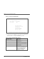
Figure 5−1 QLogic Fast! Util Main Menu
QLogic Fast! UTIL
Version 1.27
Selected Adapter
Adapter Type
I/O Address
PCI Ultra-W
8000
Fast! UTIL Options
Configuration Settings
Scan SCSI Bus
SCSI Disk Utility
Select Host Adapter
Exit Fast! UTIL
Use <Arrow keys> to move cursor, <Enter> to select option, <Esc> to backup
3.
Use the arrow keys to highlight any of the options on the main menu as
described in Table 5−1 and press the Enter key to select.
Table 5−1 QLogic Fast!Util Main Menu Options
5–2
Main Menu Option
Description
Configuration Settings
Displays the Configuration
Settings Menu
Scan SCSI Bus
Displays a list of the installed
devices at each of the SCSI IDs.
SCSI Disk Utility
Formats a device or checks for
media defects.
Select Host Adapter
Displays a screen from which you
can select which KZPBA-CA you
want to configure, if you have
more than one KZPBA-CA
installed in your system.
EK–KZPBA–UG. B01
Chapter 5. QLogic Fast!Util
5.3
Changing Configuration Settings
You can change configuration settings for a particular option, reset all settings to
their defaults, or auto–configure settings.
To change or view configuration settings, follow these steps:
1.
Use the arrow keys to move the cursor to Configuration Settings on the
Fast!Util main menu and press the Enter key. The Configuration Settings
menu appears as shown in Figure 5−2.
Figure 5−2 The Configuration Settings Menu
QLogic Fast! UTIL
Version 1.27
Selected Adapter
Adapter Type
I/O Address
PCI Ultra-W
8000
Configuration Settings
Host Adapter Settings
SCSI Device Settings
Autoconfigure SCSI Devices
Restore Default Settings
Use <Arrow keys> to move cursor, <Enter> to select option, <Esc> to backup
2.
Use the arrow keys to move to any option on the Configuration Settings
menu and press the Enter key.
5.3.1 Changing Host Adapter Settings
If you need to change Host Adapter settings from their defaults, follow these
steps:
1. Use the arrow keys to highlight Host Adapter Settings from the
Configuration Settings menu and press the Enter key. The Host Adapter
Settings appear as shown in figure 5−3.
EK–KZPBA–UG. B01
5–3
KZPBA-CA PCI-to-UltraSCSI Host Adapter
Figure 5−3 Host Adapter Settings
QLogic Fast! UTIL
Version 1.27
Selected Adapter
Adapter Type
I/O Address
PCI Ultra-W 8000
Host Adapter Settings
BIOS Address:
BIOS Revision:
Interrupt Level:
Host Adapter:
Host Adapter BIOS:
Host Adapter SCSI ID:
PCI bus DMA burst:
SCSI bus reset:
SCSI bus reset delay:
SCSI termination:
CC000
4.15
5
Enabled
Enabled
7
Enabled
Enabled
5 seconds
Auto
Use <Arrow keys> and <Enter> to change settings, <Esc> to exit
5–4
2.
Use the arrow keys to select any of the Host Adapter settings you can move
to (you can only move to settings that you can change). Press the Enter key
to toggle between options or to display a list of options. Press the Enter key
again to select an option from a list. Table 5−2 shows the host adapter
setting defaults.
3.
Press the Esc key to return to the Configuration Settings menu when you
complete the host adapter settings.
EK–KZPBA–UG. B01
Chapter 5. QLogic Fast!Util
Table 5−2 Host Adapter Settings
Setting
Range
Default
Host Adapter
Enabled or Disabled
Enabled
Host Adapter BIOS
Enabled or Disabled
Enabled
Host Adapter SCSI ID
0-7 (Fast!SCSI PCI UltraN)
7
0-15 (Fast!SCSI PCI UltraW and Fast!SCSI PCI
Ultra-D)
PCI bus DMA burst
Enabled or Disabled
Enabled
SCSI bus reset
Enabled or Disabled
Enabled
SCSI bus reset delay
0-15 seconds
5 seconds
SCSI termination
Auto, Enabled, Disabled,
High only
Auto
5.3.2 Changing SCSI Device Settings
If you need to change SCSI device settings from their defaults, follow these
steps:
1.
Use the arrow keys to move the cursor to Configuration Settings on the
Fast!Util main menu and press the Enter key. The Configuration Settings
menu appears as shown in Figure 5−2.
2.
Use the arrow keys to move the cursor to the SCSI Device Settings option on
the Configuration Settings menu and press the Enter key. The SCSI device
settings appear as shown in Figure 5−4.
EK–KZPBA–UG. B01
5–5
KZPBA-CA PCI-to-UltraSCSI Host Adapter
Figure 5−4 SCSI Device Settings
QLogic Fast! UTIL Version 1.27
Selected Adapter
Adapter Type
I/O Address
PCI Ultra-W
8000
SCSI ID:
Enable Devices
Disconnects OK
Check Parity
Negotiate Wide
Negotiate Sync
Tagged Queuing
Enable LUNs
Sync Offset
Sync Period
SCSI Device Settings
0 1 2 3 4 5 6 7 8 9 10 11 12 13 14 15
yes yes yes yes yes yes yes yes yes yes yes yes yes yes yes yes
yes yes yes yes yes yes yes yes yes yes yes yes yes yes yes yes
yes yes yes yes yes yes yes yes yes yes yes yes yes yes yes yes
yes yes yes yes yes yes yes yes yes yes yes yes yes yes yes yes
yes yes yes yes yes yes yes yes yes yes yes yes yes yes yes yes
yes yes yes yes yes yes yes yes yes yes yes yes yes yes yes yes
yes yes yes yes yes yes yes yes yes yes yes yes yes yes yes yes
8 8 8 8 8 8 8 8 8 8 8 8 8 8 8 8
12 12 12 12 12 12 12 12 12 12 12 12 12 12 12 12
Use <Tab keys> to toggle between individual or group settings
Use <Arrow keys> and <Enter> to change settings, <Esc> to exit
5–6
EK–KZPBA–UG. B01
Chapter 5. QLogic Fast!Util
3.
4.
Use the Tab key to select an entire group of settings or the arrow key to
select the setting for one SCSI ID at a time. Press the Enter key to toggle
the setting option. Table 5−3 shows the default SCSI device settings.
Press the Esc key to return to the Configuration Settings menu when you
complete the SCSI device settings.
Table 5−3 SCSI Device Settings
Setting
Range
Default
Enable Devices
Yes or No
Yes
Disconnects OK
Yes or No
Yes
Check Parity
Yes or No
Yes
Negotiate Wide
Yes or No
Yes
Negotiate Synchronous
Yes or No
Yes
Tagged Queuing
Yes or No
Yes
Enable LUNs
Yes or No
Yes
Sync Offset
Sync Period
5.3.3 Auto–configuring SCSI Devices
Use Auto–configure SCSI Device to optimize SCSI device settings. The auto–
configure option causes the KZPBA-CA to scan the devices on the SCSI bus and
set options for the devices based on each device’s capabilities. To auto–configure
SCSI devices, follow these steps:
1.
Use the arrow keys to move the cursor to Configuration Settings on the
Fast!Util main menu and press the Enter key. The Configuration Settings
menu appears as shown in Figure 5−2.
2.
Use the arrow keys to move the cursor to the Autoconfigure SCSI Devices
option on the Configuration Settings menu and press the Enter key. The
utility displays the message:
Checking SCSI ID #.
EK–KZPBA–UG. B01
5–7
KZPBA-CA PCI-to-UltraSCSI Host Adapter
3.
When the utility finishes polling the SCSI IDs, it displays a list of the SCSI
device settings, similar to the list shown in Figure 5−4.
4.
Change settings as needed. Press the Esc key to exit.
5.3.4 Restoring Default Settings
Use Restore Default Settings to restore SCSI device settings to their default
states. To restore the default settings, do these steps:
1.
Use the arrow keys to move the cursor to Configuration Settings on the
Fast!Util main menu and press the Enter key. The Configuration Settings
menu appears as shown in Figure 5−2.
2.
Use the arrow keys to move the cursor to the Restore Default Settings option
on the Configuration Settings menu and press the Enter key. The utility
displays the message:
Checking SCSI ID #.
5.4
3.
When the utility finishes polling the SCSI IDs, it displays a list of SCSI
device settings, similar to the list shown in Figure 5−4.
4.
Change settings as needed and press the Esc key to exit.
Scanning SCSI Bus
Use the Scan SCSI Bus option to determine what devices exist on the SCSI bus.
To Scan the SCSI bus, follow these steps:
1.
Use the arrow keys to move the cursor to Scan SCSI Bus option on the
Fast!Util main menu and press the Enter key.
The utility displays the message:
Checking SCSI ID #.
2.
5–8
When the utility finishes polling the SCSI IDs, it displays a list of SCSI
devices at each of the SCSI IDs.
EK–KZPBA–UG. B01
Chapter 5. QLogic Fast!Util
5.5
Formatting Devices
Use the SCSI Disk Utility option to select a device on the SCSI bus for low-level
formatting, or to check for media defects. To use the SCSI Disk Utility, follow
these steps:
1.
Use the arrow keys to move the cursor to SCSI Disk Utility option on the
Fast!Util main menu and press the Enter key.
The utility displays the message:
Checking SCSI ID #.
2.
When the utility finishes polling the SCSI IDs, it displays a list of SCSI
devices at each of the SCSI IDs.
3.
Use the up and down arrow keys to highlight a device and press the Enter
key. The Disk Utility Options menu appears.
4.
Highlight either Low-Level Format or Verify Disk Media from the Disk
Utility Options menu and press the Enter key to begin either operation.
EK–KZPBA–UG. B01
5–9
6
Troubleshooting
This chapter provides troubleshooting information to help diagnose problems that can
occur during the installation of the KZPBA-CA adapter. If you experience difficulty in installing or verifying the operation of the adapter, refer to the information in the troubleshooting tables to isolate and diagnose the problem.
6.1
Introduction
Troubleshooting is the process of isolating and diagnosing problems. This chapter provides solutions to problems that can occur during the installation of the
KZPBA-CA adapter. If you experience difficulty in installing or verifying the
adapter, use the information in this chapter to isolate and diagnose the problem.
The troubleshooting techniques described in this chapter do not identify all possible problems with your KZPBA-CA adapter, nor do the actions suggested remedy all problems. If a problem is not described, or if the actions suggested do not
solve the problem, call your Digital services representative. For problems that
may be related to the host, refer to your host system documentation.
The troubleshooting information presented in this chapter is divided as follows:
•
System Power-on Problems (Table 6–1)
•
SCSI-Device Problems (Table 6–2)
•
Boot-Sequence Problems (Table 6–3)
NOTE
Before you begin troubleshooting, ensure that the
correct version of console code (SRM, ARC and
AlphaBIOS) is loaded.
EK–KZPBA–UG. B01
6–1
KZPBA-CA PCI-to-UltraSCSI Host Adapter
6.2
System Power-on Problems
After you turn on your host system, the CPU either performs a series of self-tests
or enters the console mode. Table 6–1 describes possible problems that could occur during self-tests, specifies their probable cause, and provides corrective action.
Table 6–1 Power-on Problems Troubleshooting Table
6–2
Symptom
Probable Cause
Corrective Action
System self-tests halt
with error message or
error summary displayed on console terminal.
System detected an error
while running its self-test.
Check that the KZPBA-CA and
system boards are firmly
seated. Check connections to
external peripherals.
Record the number following
the question mark in the error
message or error summary and
call your Digital service representative.
EK–KZPBA–UG. B01
Chapter 6. Troubleshooting
6.3
SCSI Device Problems
Table 6–2 lists a SCSI device problem, specifies the probable causes, and suggests corrective actions for each probable cause.
Table 6–2 SCSI Device Troubleshooting Table
Symptom
Probable Cause
Corrective Action
SCSI device does not appear in the configuration
display after the SRM
console command,
Device cannot negotiate
wide or synchronous
transfers.
Use the EEROM configuration utility to disable
(see Chapter 4).
Duplicate SCSI IDs
Ensure that each SCSI device has a unique SCSI ID.
KZPBA-CA adapter is in
an unknown state.
Initialize the adapter with the
SRM console command,
p00>>show config
or,
SCSI device does not appear in the
List Existing SCSI Devices display selected
from the EEROM Configuration Utility.
(P00>>> init)
or,
by pressing the systems
reset button.
EK–KZPBA–UG. B01
SCSI device or bus is
hung.
Reset the SCSI bus via the
flash EEROM utility (see
Chapter 4.)
Cable is not connected to
the SCSI device.
Check cable connections.
SCSI device(s) not
plugged in and turned on
before system power up.
Power up all external SCSI
devices, and then power up
system.
6–3
KZPBA-CA PCI-to-UltraSCSI Host Adapter
Table 6–2 SCSI Device Troubleshooting Table (Continued)
Symptom
Probable Cause
Corrective Action
SCSI device . . . (con't)
SCSI bus not terminated
properly.
Ensure each end of the bus is
terminated.
Ensure devices in the middle
of the bus are not terminated.
Total length of SCSI bus
too long.
Check total length of SCSI bus
as follows:
Ultra Single-ended,
1.5 meters, maximum.
Defective SCSI device.
6.4
Replace SCSI device.
Boot Sequence Problems
Table 6–3 describes possible problems during the boot sequence, specifies their
probable cause, and suggests corrective actions.
NOTE
For the DIGITAL UNIX and DIGITAL OpenVMS
operating systems, obtain the correct device
name as described in Section 3.7. For the Windows NT operating system, obtain the correct device name as described in Section 3.6.
6–4
EK–KZPBA–UG. B01
Chapter 6. Troubleshooting
Table 6–3 Boot Sequence Troubleshooting Table
Symptom
Probable Cause
Boot failure
Incorrect boot device
was specified at the
console boot command.
Re-define the default boot device. Refer to
your system user's guide for specific
environmental parameter settings.
KZPBA-CA is not terminated properly.
Ensure each end of the SCSI bus is terminated.
KZPBA-CA is in an unknown state.
Initialize the adapter by either entering the
SRM console init command or press
the system reset button.
KZPBA-CA is not terminated properly.
Ensure each end of the SCSI bus is terminated.
Operating system not
configured correctly.
Reconfigure system software. Refer to
system documentation.
Operating system does
not contain device driver
or driver not installed
correctly.
If running "Windows NT", ensure the device driver is installed. If running DIGITAL
UNIX or DIGITAL OpenVMS, ensure that
the OS revision level supports the KZPBACA.
Device not
recognized
during boot.
EK–KZPBA–UG. B01
Corrective Action
6–5
A
EEROM Parameter Settings
This chapter describes EEROM device-specific parameters on the KZPBA-CA. It
provides a description of each parameter, its default setting, and available options. It also
lists the FIFO threshold controls and their corresponding parameter settings, the
asynchronous data setup times, and the parameter selection time-out values.
A.1 EEROM Parameter Settings
Descriptions of the host adapter parameters and device (specific) parameters
available through the Alpha AXP configuration utility appear in Tables A–1 and
A–4, respectively.
The KZPBA-CA host adapter also ships with a floppy diskette containing the
ISP1020/1040 EEROM Configuration Utility for Alpha AXP which you can use
to change parameter settings. Refer to Chapter 4 of this guide for a description of
the EEROM Configuration Utility and how to use it to change parameter settings.
EK–KZPBA–UG. B01
A–1
KZPBA-CA PCI-to-UltraSCSI Storage Adapter
Table A–1 Descriptions of Host Adapter Parameters (KZPBA-CA General
Operation)
Parameter
Default
FIFO Threshold
Description
Option
Sets the FIFO threshold point at
which burst transfers are requested
on the KZPBA-CA host adapter.
The burst transfer is triggered
differently for host memory write
operations and host memory read
operations. The bus transfer is
triggered when the FIFO byte count
reaches the threshold point for host
memory writes operations. The bus
transfer is requested when the
FIFO byte count is below the
threshold point for host memory
read operations.
See Table A–2 for the
FIFO threshold points
available and the
corresponding
parameter setting to
select each.
1
Determines whether the BIOS
recognizes the KZPBA-CA host
adapter.
Set to 0 to disable the
host adapter without
physically removing it
from your system.
Initiator SCSI ID
7
Sets the KZPBA-CA SCSI ID.
0–15
Bus Reset
Delay
1
After resetting the SCSI bus, the
firmware refrains from initiating any
SCSI activity for the number of
seconds specified by this
parameter.
0–255 seconds
Retry Count
0
Specifies the number of times the
firmware attempts to retry a
selection time-out or a busy status.
0–255 retries.
Retry Delay
1
Sets the time (in 100-ms
increments) that the firmware waits
before re-attempting an operation.
0–255 in 100-ms
increments
Sets the number of clock periods
the KZPBA-CA host adapter card
waits after driving the SCSI data
signals before asserting a SCSI bus
acknowledge signal.
See Table A–3.
1020
2
1020A
3
1040B
3
Host Adapter
Enable
Asynchronous
Data Setup
Time
FAST-10
6
FAST-20
9
A–2
EK–KZPBA–UG. B01
Appendix A. EEROM Parameter Settings
Table A–1 Descriptions of Host Adapter Parameters (KZPBA-CA General
Operation) (Continued)
Parameter
Default
Description
Option
REQ/ACK
Active Negation
1
Provides Active pull-up assist in
single-ended mode. (The REQ and
ACK signals are pulled up.) By
enabling active negation, the
KZPBA-CA host adapter is less
sensitive to an imperfect SCSI bus.
Set to 0 to disable the
active negation.
Data Line Active
Negation
1
Provides active pull-up assist in
single-ended mode. (The SD15-0
and SDP1-0 signals are pulled up.)
By enabling active negation, the
KZPBA-CA host adapter is less
sensitive to an imperfect SCSI bus.
Set to 0 to disable the
active negation.
Data DMA Burst
Enable
1
When set to 1, performs burst
transfers on the data DMA channel.
When set to 0, data is
transferred in
nonburst mode with
each cycle initiated by
a new address phase.
Command DMA
Burst Enable
1
When set to 1, performs burst
transfers on the data DMA channel.
When set to 0, data is
transferred in
nonburst mode with
each cycle initiated by
a new address phase.
Tag Aging
8
Insures tagged commands are not
lost in the target device. Tag aging
is a backup to the time-out
mechanism.
0–255 cycles, drive
dependent.
Low
Termination
Enable
1
Provides termination to the loworder eight bits.
Set to 0 if termination
not required on the
board. See
termination section of
this guide for
termination
requirements.
EK–KZPBA–UG. B01
A–3
KZPBA-CA PCI-to-UltraSCSI Storage Adapter
Table A–1 Descriptions of Host Adapter Parameters (KZPBA-CA General
Operation) (Continued)
Parameter
Default
High
Termination
Enable
1
Provides termination to the highorder eight bits.
Set to 0 if termination
not required on highorder 8-bits, or not
required on the
board. See
termination section
of this guide for
termination
requirements.
Selection Timeout
250
Sets the selection phase time-out
value.
Table A–4 shows the
time-out values
available.
Maximum
Queue Depth
256
Specifies the maximum number of
outstanding commands issued to
each SCSI target. When the
number is reached, new commands
are returned with Queue Full
Status.
0 to 64K commands
FIFO 128
Threshold
Enable
0
Enables or disables the FIFO burst
length of 128 bytes.
Set to 1 to enable the
FIFO 128 Threshold.
Fast RAM
enable
1
Provides no wait state, fastest
performance.
Set to 0 to require a
wait state, slower
performance. (Not
recommended.)
SCSI Reset
Disable
0
Allows the BIOS code to issue a
SCSI reset during BIOS
initialization.
Set to 1 to prevent
the BIOS code from
issuing a SCSI reset
during BIOS
initialization.
Enable Auto
Termination
1
Enables or disables the adapter’s
auto termination. Auto termination
circuitry senses if proper SCSI bus
termination is present and
terminates the bus, if not.
Set to 0 to disable
auto termination.
A–4
Description
Option
EK–KZPBA–UG. B01
Appendix A. EEROM Parameter Settings
Table A–2 FIFO Threshold Controls and Corresponding Parameter Setting
Parameter
FIFO Threshold Point
Enable FIFO 128
128 bytes full during host memory writes.
128 bytes empty during host memory reads.
3 (default)
64 bytes full during host memory writes.
64 bytes empty during host memory reads.
2
32 bytes full during host memory writes.
32 bytes empty during host memory reads.
1
16 bytes full during host memory writes.
16 bytes empty during host memory reads.
0
8 bytes full during host memory writes.
8 bytes empty during host memory reads.
Table A–3 Asynchronous Data Setup Time
Parameter (h)
Set-up Time
(in clock periods)
Parameter (h)
Set-up Time
(in clock periods)
0
1.0
8
5.0
1
1.5
9 (Default)
5.5
2
2.0
A
6.0
3
2.5
B
6.5
4
3.0
C
7.0
5
3.5
D
7.5
6
4.0
E
8.0
7
4.5
F
8.5
EK–KZPBA–UG. B01
A–5
KZPBA-CA PCI-to-UltraSCSI Storage Adapter
Table A–4 Descriptions of Device EEROM Parameters
(KZPBA-CA to Device Interaction)
Parameter
Default
Re-negotiate-onError
1
Set to 1, enables re-negotiation
for synchronous and wide data
transfers (if wide transfers are
enabled) after a hard reset,
power cycle, or a bus device
reset.
Set to 0 to disable renegotiation on error.
Stop Queue on
Check Condition
0
When a command is returned
with a Check Condition status,
new commands are issued by
the KZPBA-CA to the device.
Set to 1 to prevent the
KZPBA-CA from issuing
new commands when a
command is returned
with a Check-Condition
status.
Auto Request
Sense
1
When a command is returned
with Check Condition status the
KZPBA-CA issues a request
command to determine cause.
Set to 0 to disable the
request command. The
computer’s OS must be
able to correct the
problem and notify the
adapter when it can
continue issuing
commands.
Tagged Queuing
1
Allows the drive to queue
multiple commands when
enabled.
Set to 0 to disable tag
queuing.
Synchronous
Data Transfers
1
Specifies the number of clock
cycles in the data hold period for
synchronous data transfers.
Set to 0 to disable
synchronous data
transfers.
Wide Data
Transfers
1
Sets the drive to support wide
SCSI data transfers.
Set to 0 to disable widedata transfers.
Device Enable
1
The system BIOS and drivers
recognize the drives attached to
the KZPBA-CA.
Set to 0 for the BIOS
and drivers to ignore the
drives.
Parity Checking
1
The KZPBA-CA checks for odd
parity on data received from the
SCSI bus, the received parity is
passed to the SCSI FIFO.
When set to 0, the
KZPBA-CA does not
check for odd parity on
data received from the
SCSI bus and odd parity
is generated for the
SCSI FIFO.
A–6
Description
Option
EK–KZPBA–UG. B01
Appendix A. EEROM Parameter Settings
Table A–4 Descriptions of Device EEROM Parameters
(KZPBA-CA to Device Interaction)(Continued)
Parameter
Default
Disconnect
Allowed
1
Determines whether the drive can
sever its communications link.
Allows the drive to sever the
communications link when the
KZPBA-CA issues a command. The
KZPBA-CA must re-establish the
link (through a reconnect) when it is
ready to continue executing.
When set to 0,
disconnects are not
allowed.
Execution
Throttle
16
Specifies the number of tagged
commands the KZPBA-CA can send
to the drive until the command
queue is full. When the queue is full,
the KZPBA-CA waits until there are
no outstanding commands before
sending the tagged commands.
0–255 commands.
Specifies the minimum REQ/ACK
period (4-ns increments) for a
synchronous data transfer.
25–100 4 ns
increments.
Specifies the maximum number of
requests (REQ) that can be sent
during a synchronous data transfer
before an acknowledge (ACK) is
received.
0–12 requests.
Synchronous
Period
FAST-10
25
FAST-20
12
Synchronous
Offset
FAST-10
12
FAST-20
8
Description
Option
Table A–5 Selection Time-out Values
Parameter
Resulting Time-out
25
25 µs
50
50 µs
75
75 µs
100
100 µs
250
250 ms
500
500 ms
750
750 ms
1000
1 sec
EK–KZPBA–UG. B01
A–7
Reader’s Comments
Manual Order Number:
EK–KZPBA–UG. B01
Digital is committed to providing the best possible products and services. Since our manuals are
important components of our products, we value your comments, corrections, and suggestions for
improvements. Please take a few minutes to fill out and return this form, attaching additional sheets, if
needed. Thank you.
Manual Rating
Excellent
Accuracy (correct presentation of facts)
Completeness (adequate information)
Clarity (easy to understand)
Organization (logical sequence of information)
Layout (easy to follow subject matter)
Indexing (easy to locate desired information)
[
[
[
[
[
[
Good
]
]
]
]
]
]
[
[
[
[
[
[
]
]
]
]
]
]
Errors Noted (please include page, paragraph, table or figure number)
Most-Liked Features
Least-Liked Features
Suggestions for Improvement
Return Address:
Customer Research
Response Center
Digital Equipment Corporation
334 South Street, SHR3-2/S27
Shrewsbury, MA 01545
Name
Title
Company
Street Address
City State ZIP
Phone
Fair
Poor
[ ]
[ ]
[ ]
[ ]
[ ]
[ ]
[ ]
[ ]
[ ]
[ ]
[ ]
[ ]