1
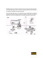
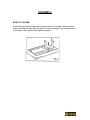
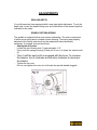
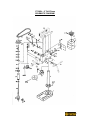
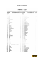
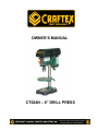
OWNER’S MANUAL CT024N – 8” DRILL PRESS INDEX GENERAL SAFETY INSTRUCTIONS SPECIFIC SAFETY INSTRUCTIONS PAGE 3 PAGE 4 Features Electrical Information Unpacking & Cleaning PAGE 5 PAGE 6 PAGE 7 Assembly Base to Column Drill Press Head to Column Feed Handle Pulley Cover Mounting the Drill Press PAGE 8 PAGE 9 PAGE 9 PAGE 10 PAGE 10 Adjustments Changing Spindle Speeds Table Adjustments Drilling Depth Spindle Return Spring PAGE 11 PAGE 11 PAGE 12 PAGE 12 Operation Drilling Speeds Metalworking Woodworking Feeding PAGE 13 PAGE 13 PAGE 13 PAGE 13 Maintenance PAGE 14 Schematic Diagram Parts List PAGE 15 PAGE 16 Warranty PAGE 17 2 GENERAL SAFETY INSTRUCTIONS EXTREME CAUTION SHOULD BE USED IN OPERATING ALL POWER TOOLS. KNOW YOUR POWER TOOL, BE FAMILIAR WITH ITS OPERATION. READ THE OWNER’S MANUAL AND PRACTICE SAFE USAGE PROCEDURES AT ALL TIMES. CONNECT your machine ONLY to the matched and specified power source. WEAR SAFETY GLASSES, HEARING PROTECTION and SAFETY SHOES when operating heavy machinery. Always wear safety glasses. DO NOT wear loose clothing or jewellery when operating machinery. A Safe Environment is important. Keep the area free of dust, dirt and other debris in the immediate vicinity of the machine. BE ALERT! Do Not Use prescription or other drugs that may affect your ability or judgement to safely use this machine. DISCONNECT the power source when making other adjustments or repairs. NEVER leave an operating tool unattended. NEVER reach over the table when the tool is in operation. ALWAYS keep blades, knives or bits sharp and properly aligned. ALWAYS keep all safety guards in place and ensure their proper function. ALWAYS make sure that any tools used for adjustments are removed before operating the machine. ALWAYS secure your work with the appropriate clamps or vises. ALWAYS keep bystanders safely away while operating machinery. THINK SAFETY. WORK SAFELY. Never attempt a procedure if it does not feel safe or comfortable. 3 SPECIFIC SAFETY INSTRUCTIONS Always make certain that you clamp down any object that you are drilling into. When drilling, make sure that you are using the correct speed for the material being drilled. Clear the drill press table of all objects before turning the tool on. Keep hands and fingers safely away from the spinning drill bits. NEVER start the drill press with the drill bit in contact with the work piece. Make certain that the drill bit is securely tightened into the drill chuck. NEVER wear gloves while operating a drill press. Make certain that the table lock is securely tightened before using the drill press. Never attempt to drill any material that is not flat without using a secure jig for that specific work piece. Always remove the drill bit before leaving the machine. 4 DRILL PRESS FEATURES As part of the growing line of Craftex woodworking equipment, we are proud to offer the CT024N Drill Press. The Craftex name guarantees Craft Excellence. By following the instructions and procedures laid out in this owner’s manual, you will receive years of excellent service and satisfaction. The CT024N is a professional tool and like all power tools, proper care and safety procedures should be adhered to. This little drill press features solid cast iron construction, depth stop adjustment and lockable switches. Comes complete with pulleys, belts, arbor, drill chuck and motor. Specifications Size: 8" Motor: 1/3 HP Chuck: 1/2" Spindle: JT33 Table: 7" Round Speeds: 5 Height: 23" Weight: 20 kg. Carton size: 14" x 8 1/2" x 17 1/2" GROUNDING INSTRUCTIONS 5 In the event of a malfunction or breakdown, grounding provides the path of least resistance for electrical current and reduces the risk of electrical shock. This tool is equipped with an electrical cord that has an equipment grounding conductor and a grounding plug. The plug MUST be plugged into a matching outlet that has been properly installed and grounded in accordance with ALL local codes and ordinances. DO NOT MODIFY THE PLUG PROVIDED. If the provided plug will not fit the electrical outlet, have the proper outlet installed by a qualified licensed electrician. IMPROPER CONNECTION of the equipment grounding conductor can result in risk of electrical shock. The conductor wire with the green insulation (with or without yellow stripes) is the equipment-grounding conductor. If repair or replacement of the electrical cord or plug is required, DO NOT connect the equipment grounding conductor to a live terminal. If in doubt about these instructions consult a qualified, licensed electrician. USE ONLY A THREE-WIRE EXTENSION CORD with a 3-prong grounding plug and three-hole receptacles that accept the tool’s plugs as shown. It is recommended that stationary tools be assigned to a dedicated 15 amp circuit using #12 wire. UNPACKING AND CLEANING 6 Carefully unpack your drill press and all of its parts. Compare the carton contents with the illustration below. Do not discard any packing material until the drill press is completely assembled and operating properly. Your drill press and some of its parts have been coated with a protective lubricant that should be removed before the machine is assembled. This can be done with a soft cloth moistened with non-corrosive kerosene or mineral spirits. 7 ASSEMBLY BASE TO COLUMN Select the base and the drill press column from the loose parts. Select the four bolts from the parts bag. Align the holes of the post flange to the threaded holes in the base. Insert the bolts and tighten securely. . 8 ASSEMBLY DRILL PRESS HEAD TO COLUMN. Lift the drill press head carefully and position it over the column. The column fits into the drill press mounting hole. Make certain the mounting hole is properly seated on the column. Line the drill press head up with the table and base and then tighten the two set-screws using the supplied hex wrench. FEED HANDLE. Fit the feed handle onto the shaft. 9 ASSEMBLY PULLEY COVER Insert washer and screw through the hole in the pulley cover, thread the knob onto the screw and then tighten. MOUNTING THE DRILL PRESS Your drill press must be securely fastened to prevent the machine from tipping, sliding or walking during operation. There are two base holes provided for this. 10 Adjustments CHANGING SPINDLE SPEEDS Disconnect the drill press from its power source. Open the pulley cover. Loosen the slide bar knob Move the motor to the front to loosen the tension on both belts. Relocate the belts to the pulley steps appropriate to the required spindle speed To tighten the belt tension, move the motor toward the rear of the drill press. Tighten the slide bar knob Close the pulley cover. Test run the drill press to check the belts for proper tension. TABLE ADJUSTMENTS To tilt the table from 0 degrees to 45 degrees left or right, loosen the table locking bolt, tilt the table to the desired angle and tighten the bolt. When returning the table to 0 degrees tighten the bolts. 11 ADJUSTMENTS DRILLING DEPTH Your drill press has been equipped with a new type depth adjustment. To set the depth stop, loosen the depth locking nuts and rotate them to the desired depth as indicated on the scale. SPINDLE RETURN SPRING The spindle is equipped with an auto-return mechanism. The main components of which are a spring and a notched chrome housing. The spring was properly adjusted at the factory and should not be readjusted unless absolutely necessary. If required, proceed as follows: - Unplug the drill press. - Loosen the two housing nuts (1) approximately 1/4". - Firmly hold the spring housing (2) and pull it out so it clears the raised notch (3). - Turn it until the next notch is engaged with the boss. To increase the tension, turn it clockwise and counter-clockwise to decrease the tension. - Tighten the two nuts. Do not over-tighten the nuts, as it will make the spindle handle sluggish. 12 OPERATION Note: As with any new piece of equipment, the owner/operator should use scrap material in order to become accustomed to it. DRILLING SPEEDS The following is intended to be a general rule-of-thumb, not specific information. Important drilling speed factors are the type of material, hole size, the type of drill bit/cutter and the desired cut quality. The smaller the drill bit, the higher the speed required and soft materials generally require a higher speed while hard materials a slower speed. METAL WORKING A metal workpiece (like all work) should be firmly clamped to the drill press table and the table securely locked. NEVER hold the workpiece with your bare hands. The drill bit may grab and cause serious personal injury. Flat metal pieces should be backed with scrap wood and clamped. Irregular-shaped pieces should be blocked and clamped. WOODWORKING Metal-piercing twist drills may be used on wood but the preferred choice is bradpoint bits or Forstner-type bits. Do not use auger bits, as they will tend to lift off the table. To prevent tear-out when drilling through a workpiece, back it with a piece of scrap wood. FEEDING Be aware of the sound of the drill press motor when drilling. Do not rotate the feed handles too quickly as the belts may slip or the motor may stall. Feeding too slowly may cause the drill bit to heat up and possibly burn the workpiece. 13 MAINTENANCE Disconnect the Power Cord before Working on the Machine Although machines such as this drill press are designed to work in wood shops and metal shops, sawdust and metal shavings are not friendly to electrical motors. The owner should routinely (once a month) blow out or vacuum metal shavings and sawdust from around the motor cover, the pulley housing, the drill press table and other surfaces. The drill press table should be cleaned after each use. The application of a light coat of paste wax on drill press column and the table will help keep these surfaces clean and rust-free. The bearings in the quill and V-belt assembly are permanently greased and sealed. A light application of oil to the quill every three months is recommended. Lubricate other moving parts as well to keep the drill press well maintained. 14 CT024N – 8” Drill Press SCHEMATIC DIAGRAM 15 CT024N – 8” Drill Press 16 CRAFTEX 2 YEAR LIMITED WARRANTY Craftex warrants every product to be free from defects in materials and agrees to correct such defects where applicable. This warranty covers two years for parts and 90 days for labour (unless specified otherwise), to the original purchaser from the date of purchase but does not apply to malfunctions arising directly or indirectly from misuse, abuse, improper installation or assembly, negligence, accidents, repairs or alterations or lack of maintenance. Proof of purchase is necessary. All warranty claims are subject to inspection of such products or part thereof and Craftex reserves the right to inspect any returned item before a refund or replacement may be issued. This warranty shall not apply to consumable products such as blades, bits, belts, cutters, chisels, punches etceteras. Craftex shall in no event be liable for injuries, accidental or otherwise, death to persons or damage to property or for incidental contingent, special or consequential damages arising from the use of our products. RETURNS, REPAIRS AND REPLACEMENTS To return, repair, or replace a Craftex product, you must visit the appropriate Busy Bee Tools showroom or call 1-800-461-BUSY. Craftex is a brand of equipment that is exclusive to Busy Bee Tools. For replacement parts directly from Busy Bee Tools, for this machine, please call 1-800-461BUSY (2879), and have your credit card and part number handy. • All returned merchandise will be subject to a minimum charge of 15% for re-stocking and handling with the following qualifications. • Returns must be pre-authorized by us in writing. • We do not accept collect shipments. • Items returned for warranty purposes must be insured and shipped pre-paid to the nearest warehouse (see locations on inside back cover of this manual). • Returns must be accompanied with a copy of your original invoice as proof of purchase. Returns must be in an un-used condition and shipped in their original packaging a letter explaining your reason for the return. Incurred shipping and handling charges are not refundable. • Busy Bee will repair or replace the item at our discretion and subject to our inspection. • Repaired or replaced items will be returned to you pre-paid by our choice of carriers. • Busy Bee reserves the right to refuse reimbursement or repairs or replacement if a third party without our prior authorization has carried out repairs to the item. • Repairs made by Busy Bee are warranted for 30 days on parts and labour. • Any unforeseen repair charges will be reported to you for acceptance prior to making the repairs. • The Busy Bee Parts & Service Departments are fully equipped to do repairs on all products purchased from us with the exception of some products that require the return to their authorized repair depots. A Busy Bee representative will provide you with the necessary information to have this done. • For faster service it is advisable to contact the nearest Busy Bee location for parts availability prior to bringing your product in for repairs. 17 18 19 20 21