1
SPM522D
Digitally Controlled
Stereo Preamp/Mixer
Operation Manual
®
5/26/98
Biamp Systems, 10074 S.W. Arctic Drive, Beaverton, Oregon 97005 U.S.A. (503) 641-7287 http://www.biamp.com
an affiliate of Rauland-Borg Corp.
SPM522D
TABLE OF CONTENTS
Front & Rear Panel Features
INTRODUCTION
pgs. 2 & 3
Remote Controls
pg. 4
Setup / Options
pg. 6
Configuration - PC Control Software
pg. 7
Computer Control
pg. 15
Applications
pg. 18
Block Diagram
pg. 22
Specifications
pg. 23
®
The ADVANTAGE SPM522D provides five stereo line inputs, two mono
mic/line inputs, and two independent stereo outputs. With complete
programmability and remote control, including input source selection for each
output, page-zone routing of mic/line inputs, automatic page-over ducking, and
storage of 8 non-volatile memory presets, the SPM522D is ideally suited for
applications such as meeting rooms, restaurants, bars, and aerobics studios.
The SPM522D is extremely versatile, allowing the contractor to customize setup for each specific application.
SPM522D features include:
♦ five stereo line inputs, with trim controls for level adjustment
♦ fifth input 30dB pad for input from distributed speaker lines
♦ fifth input 'override' via contact-closure or signal activation
♦ two balanced mic/line inputs, including inserts for processing
♦ 40dB trim, 30dB pad, and peak indicator on mic/line inputs
Warranty
♦ +24 volt phantom power switchable on each mic/line input
♦ mic/line 'page-over' via contact-closure or signal activation
♦ independent stereo main & stereo zone balanced outputs
♦ stereo limiters with threshold control for each stereo output
♦ rear panel switches convert main or zone outputs to mono
♦ remote control selection of stereo source for each output
♦ remote control of tone and balance for each stereo source
♦ remote control of levels and muting for each mic/line input
♦ remote control of levels and muting for each stereo output
♦ four memory presets for each output, with levels and source
♦ 'combined' mode selectable for room combining applications
♦ remote control via infrared, wall-mount, and/or custom panel
♦ computer control and configuration via RS-232 serial port
®
♦ PC control software for Windows 95 & serial cable included
♦ remote translator input for third-party 'serial' controllers
♦ front panel display of presets, source selections, and levels
♦ external remote display panels available as an option
♦ incorporates AES recommended grounding practices
♦
marked and UL / C-UL listed power source
♦ covered by Five-Year "Gold Seal" Warranty
?
After reading this manual, if you have any questions or need technical
assistance, please call Biamp Systems toll-free 1-800-826-1457.
☎
1
FRONT & REAR PANEL FEATURES
zone main
max
ADVANTAGE SPM522D
Stereo Preamp Mixer
preset
channel
mic
main
zone
min
A
B
C
D
E
F
G
H
1
2
3
4
5
1
Setup
2
mute
Error
(1)
IR
on
(2)(3)(4) (5) (6)
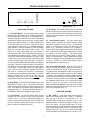
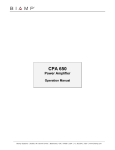
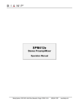
FRONT PANEL FEATURES
(7)
(4) IR Indicator: This red LED indicates when any information
has been received via remote control (see Remote Controls on pg.
4). If the IR and Error LEDs flash simultaneously, this may be an
indication of improper installation. Check location and wiring of all
infrared receivers.
(1) Front Panel Display: This LED display indicates settings
which affect the Main and Zone outputs. Settings are changed via
Remote Controls (pg. 4), Setup (pg. 6), or Configuration (pg. 7).
The Main Preset (A~D) and Zone Preset (E~H) LEDs indicate
which preset is currently active for each output. A preset contains
all of the source and level settings for an output, which are stored
in non-volatile memory for future recall. Presets can be used to
simply change inputs and levels, or to completely re-configure
system operation. When the SPM522D is in 'Room-Combining
Mode', only one Preset LED will be lit (Main or Zone). The
Channel (1~5) LEDs indicate which stereo input channel is
selected for each output. Each channel selection may include its
own customized tone and balance settings. The Mic (1 & 2) LEDs
indicate which mic/line inputs are assigned to each output. When
a mic/line input is set for 'gated' operation, the associated LEDs
will light only when the input is active (gate open). The Main and
Zone (min~max) LED ladders indicate the relative level setting for
each output. These are not signal level meters. Only one LED in
each ladder will be on, indicating the overall level ('fader') setting
for that output. The Mute LEDs indicate when either output is
muted. When an output is muted, the associated level LED will
also remain on. Decreasing the level setting of a muted output
only reduces the level that output will return to when it is un-muted.
However, increasing the level setting of a muted output will
automatically un-mute that output. Similar external Remote
Display Panels are optional (see Remote Controls on pg. 5).
(5) Internal Infrared Receiver: This green infrared photo
detector receives commands from optional hand-held Infrared
Transmitters (see Remote Controls on pg. 4). A transmitter will
operate up to 30 feet from the receiver. For best results, there
should be an unobstructed line-of-sight from transmitter to
receiver. When infrared commands are received, the IR LED will
flash. If the IR and Error LEDs flash simultaneously, this may be
an indication of improper installation. The Internal Infrared
Receiver should not be located in direct sunlight, or pointed
directly at fluorescent lighting. Internal Infrared Receiver control
functions are assignable during Configuration (see Configuration
on pg. 10). If desired, the Internal Infrared Receiver may be
manually bypassed (see Options on pg. 6).
(6)(7) Power Switch & Indicator: When the Power switch is
turned on, the Power LED will light. When power is turned off, all
'current mix' settings (presets, sources, & levels) will be stored in
non-volatile memory and recalled when power is turned back on.
NOTE: The 'current mix' settings are stored only after 5 seconds
of inactivity. If an adjustment to a setting is made less than 5
seconds before power is turned off, the last adjustments that were
followed by a 5 second pause will be the settings stored for recall.
Any adjustments made, without a full 5 second pause before
power off, will be lost (not stored in non-volatile memory).
During Configuration the SPM522D may instead be set to always
recall Main Preset A and Zone Preset E when power is turned
back on (see Configuration on pg. 11).
(2) Setup Button: This momentary push-button is used to enter
Setup Mode (see Setup on pg. 6). Setup Mode allows preset
mixes to be defined and stored in non-volatile memory for future
recall. Setup Mode may be disabled during Configuration (see
Configuration on pg. 11). The Setup button is also used to return
the SPM522D to factory default settings (see Setup on pg. 6).
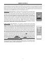
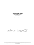
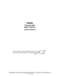
REAR PANEL FEATURES
(1) Mic 1 & Mic 2: These plug-in barrier strips provide the
balanced mono mic/line inputs for Mic 1 & Mic 2. For balanced
input, wire high to (+), low to (-), and ground to ( ). For
unbalanced input, wire high to (+), and ground to both (-) & ( ).
Additional terminals are provided for 'page-over' ducking of the
stereo input signals. By wiring (signal present) to (mute),
automatic ducking will occur whenever signal is present at the Mic
Input. Manual ducking utilizes a switch or contact-closure wired
between (mute) & ( ). Mic 1 & Mic 2 functions are assignable
during Configuration (see Configuration on pg. 7 and pgs. 11~13).
(3) Error Indicator: This red LED indicates when unusable
information has been received via remote control (see Remote
Controls on pg. 4). If an error in transmission/reception of a
command occurs, the Error LED will flash. The Error LED will also
flash if a command is received that has been user defined as
having ‘no action’ (see Configuration on pg. 9).
ý
ý
ý
2
FRONT & REAR PANEL FEATURES
(12)
R
an affiliate of
Rauland-Borg Corp.
(11)
outputs
L
R
L
zone
limit
(10)
main
limit
zone
main
(7)
2
1
level
level
level
(4)
L
mic 1
patch
(3)
pad
limit
main out
(1)
phtm mute
power
signal present
on
R
-20dB 0dB
3
2
+10
1
override
sensitivity
0
serial port
DC
out
remote display
remote
translator override
(17)
(16)
(15)
(14)
(13) (9)
10
5
4
level
level
-20dB 0dB
mic 2
patch
4
5
R
L R
L
mic 2
pad
trim
0dB
30dB
phtm mute
power
signal present
on
-20dB 0dB
+10
override
(8)
(6)
(2) Phantom Power: When depressed, these switches supply
+24 Volts to the respective Mic Inputs. CAUTION: Use only with
condenser microphones. Turn levels down before switching.
For best performance, set Limit Threshold so the Limit Indicator
lights when the maximum desired output level is reached.
(12) Main & Zone Outputs: These plug-in barrier strips provide
the balanced stereo line-level Main & Zone Outputs. For balanced
output, wire high to (+), low to (-), and ground to ( ). For
unbalanced output (-6dB gain), wire high to (+) and ground to ( ),
leaving (-) unconnected. Main & Zone Outputs include optional
internal 20dB pads. These pads are useful in applications where
the amplifiers have no level controls. Two pair of jumpers (J6 & J7
for Main; J4 & J5 for Zone) are located on the right edge of the
upper circuit board. To activate either 20dB pad, move both
jumper straps backward one pin, toward the rear panel (see
diagrams below). For access instructions, see Options on pg. 6.
(3) Trim, Pad, & +10 Indicator: The Trim controls adjust gain at
the respective Mic Inputs to compensate for different signal levels.
For best performance, set Trim so the +10 Indicator is activated
only by occasional peaks in signal level. Depress the Pad switch
when input signal levels exceed normal operating range of the
Trim control, or when line-level input is desired.
ý
ý
(4) Mic 1 & Mic 2 Patch: These 3-conductor 1/4" phone jacks
are for connection of other Advantage products (or signal
processors) to the respective Mic Inputs. Patch jacks are wired
with Tip as send (output), Ring as return (input), and Sleeve as a
common ground.
MAIN
ZONE
-20dB
0dB
0dB
J6
(5) Stereo Inputs 1~3: These RCA connectors provide the
unbalanced stereo line-level inputs for Channels 1~3.
-20dB
(6) Stereo Inputs 4 & 5: This plug-in barrier strip provides the
unbalanced stereo line-level inputs for Channels 4 & 5. Channel 5
includes an optional internal 30dB pad (see Options on pg. 6).
J7
sig pres
high
override
low
IR3
gnd
gnd
IR2
IR3
gnd
inputs
IR2
gnd
-20dB 0dB
limit
2
1
chassis gnd
trim
0dB
30dB
-20dB 0dB
zone out
(2)
mic 1
stereo
mono
27V ~
15 Watts MADE IN U.S.A.
50/60 Hz
class 2 wiring
(5)
3
J5
Portland, Oregon
J4
BIAMP SYSTEMS
(13) Translator: These plug-in barrier strip terminals accept
certain third-party remote controls, which use the 'serial' protocol.
The Low input is for controls with low idle (-15VDC ~ +2VDC). The
High input is for controls with high idle (+2VDC ~ +15VDC).
Translator control functions are assignable during Configuration
(see Configuration on pg. 10).
(7) Level 1~5: These controls adjust gain at the respective
Stereo Inputs to compensate for different signal levels. For best
performance, reduce gain only on channels having higher levels.
(14) Remote 1 & Remote 2: This plug-in barrier strip accepts two
optional remote controls (see Remote Controls on pg. 4). Remote
controls may be infrared, wall-mount, and/or customized, and may
be wired up to 2000 feet away from the unit. Remote 1 & Remote
2 control functions are assignable during Configuration (see
Configuration on pg. 10).
(8) Override Sensitivity: This control adjusts the threshold level
at which Channel 5 Override will occur, when being triggered by
signal present at the Channel 5 Input (see Override below).
(9) Override: These plug-in barrier strip terminals provide
Channel 5 Override, which is a priority selection of the Channel 5
input over all other stereo inputs. Wiring (sig pres) to (override)
causes automatic override whenever signal is present at the
Channel 5 Input. Manual override uses a contact-closure wired
between (override) & (gnd). Override functions are assignable
during Configuration (see Configuration on pg. 14).
(15) Remote Display: This 5-pin DIN (female) connector
provides an output for optional Remote Display Panels (see
Remote Controls on pg. 5).
(16) DC Out: This 6-pin Modular jack supplies ±12 VDC @ 10mA
max., for powering external accessory devices.
(10) Stereo/Mono: When depressed, these switches combine
the respective stereo signals into a mono sum, which is then fed
equally to both the Left & Right outputs.
(17) Serial Port: This 9-pin Sub D (male) connector provides an
RS-232 Serial Port. PC Control Software and a serial cable are
provided (see Configuration on pg. 7). The Serial Port also allows
remote control via computer, or via third-party controllers which
use the 'RS-232' protocol (see Computer Control on pg. 15).
(11) Limit Threshold & Indicator: These controls adjust the
threshold level at which the respective stereo limiters will activate.
3
REMOTE CONTROLS
The type and quantity of remote controls is optional for the SPM522D. Remote control affects source selections, preset selection, mic/line
input levels, and main/zone output levels. Remote controls may be added at any time, and do not require the SPM522D to be modified,
opened, or removed from a rack. There are five types of remote controls available: The Infrared Transmitter, the Infrared Receiver, the
Wall-Mount Panel, the Remote Interface Kit, and the Remote Display Panel. The SPM522D may also be controlled via computer and
certain third-party controllers. NOTE: Remote controls come with complete instructions.
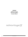
Infrared Receiver (Biamp #909-0030-00): The Receiver consists of a black plastic box, containing an infrared
photo detector, an LED indicator, and five screw terminals. To install Receiver, first take off front cover by
removing four screws. Mount Receiver to wall or other surface, using two screw holes on back cover (screws
not included). Receiver should not be mounted in direct sunlight, or pointed directly at fluorescent lighting. For
best results, there should be an unobstructed line-of-sight from Transmitter to Receiver. The Receiver may be
wired up to 2000 feet from the SPM522D, using 2-conductor shielded cable (not included). Route cable through
access hole on bottom of Receiver. Three screw terminals inside the Receiver ("GND", "IR2", & "IR3")
correspond to "Remote" terminals on rear of SPM522D. Connect cable shield to "GND" terminals at each end.
Use conductors to connect "IR2" to "IR2" & "IR3" to "IR3". Replace Receiver front cover. The LED indicator
inside Receiver lights when infrared information is detected. NOTE: The Infrared Receiver also includes two
'Remote Translator' terminals ("GND" & "XLATE"), which allow remote control of the SPM522D via third-party
'serial' controllers. Complete instructions are included with the Infrared Receiver.
InfraRed Transmitter (Biamp #909-0064-00): The Transmitter is a hand-held controller, which transmits
infrared codes unique to Biamp. Therefore, the Transmitter should not affect any other infrared controlled
equipment (such as TVs or VCRs). Likewise, other infrared controllers will not provide proper control of Biamp
equipment. The Transmitter requires two AAA batteries, which are included with the unit (user installed). The
Transmitter has twenty-eight buttons. Main (1~5) buttons select which stereo input channel (plus tone & balance
settings) is routed to the Main output. Main (A~D) buttons select the desired preset for the Main output. Zone
(1~5) buttons select which stereo input channel (plus tone & balance settings) is routed to the Zone output.
Zone (E~H) buttons select the desired preset for the Zone output. From the factory, button D/5 (Main) and H/5
(Zone) select stereo input channel #5 to be routed to the respective outputs. However, during Configuration
each of these buttons may be re-defined to instead recall the respective D & H presets (see Configuration on pg.
9). During Setup Mode the Main (A~D) and Zone (E~H) buttons are used to store the respective presets (see
Setup on pg. 6). The MUTE buttons (Mic 1, Mic 2, Zone, & Main) turn off the respective mic/line input or stereo
output signals. The Vol ▲ & Vol ▼ buttons (Mic 1, Mic 2, Zone, & Main) adjust the level setting of the respective
mic/line input or stereo output signals. Decreasing the level setting of a muted input/output only reduces the
level that input/output will return to when it is un-muted. However, increasing the level setting of a muted
input/output automatically un-mutes that input/output. When a mic/line input is set for 'gated' operation, level
settings can be adjusted only when the input is active (gate open). The way in which an SPM522D responds to
remote control buttons may be completely re-defined during Configuration (see Configuration on pg. 9) For best
results, there should be an unobstructed line-of-sight from Transmitter to receiver. The Transmitter will operate
up to 30 feet from a receiver. In addition to the Infrared Receiver described above, receivers are also included
on the SPM522D, the Wall-Mount, and the Remote Display Panel.
4
InfraRed Receiver
External Receiver
(Biamp #909-0030-00)
SPM 522D
1
2
A
B
MAIN
preset
3
4
C
D 5
1
2 ZONE 3
E
F
MUTE
VOL
preset
4
G
H 5
MUTE
MUTE
MUTE
VOL
VOL
VOL
VOL
VOL
VOL
VOL
MIC 1
MIC 2
ZONE
MAIN
Infrared Transmitter
(Biamp #909-0064-00)
REMOTE CONTROLS
Wall-Mount (Biamp #909-0074-00): The Wall-Mount is a "hard-wired" control, which is powered
by the SPM522D. There are no batteries to wear out, and it is not easily lost or stolen. The wallmount may be wired up to 2000 feet from the SPM522D, using 2-conductor shielded cable (not
included). To install Wall-Mount, first remove mounting box from front panel. Route cable
through "knock-out" hole on rear of mounting box. Install mounting box in wall or panel. Three
screw terminals on circuit board ("GND", "IR2", & "IR3") correspond to "Remote" terminals on
rear panel of SPM522D. Connect cable shield to "GND" terminals at each end. Use conductors
to connect "IR2" to "IR2" & "IR3" to "IR3". Install front panel on mounting box. The Wall-Mount
has twenty-eight buttons. Main (1~5) buttons select which stereo input channel (plus tone &
balance settings) is routed to the Main output. Main (A~D) buttons select the desired preset for
the Main output. Zone (1~5) buttons select which stereo input channel (plus tone & balance
settings) is routed to the Zone output. Zone (E~H) buttons select the desired preset for the Zone
output. From the factory, button D/5 (Main) and H/5 (Zone) select stereo input channel #5 to be
routed to the respective outputs. However, during Configuration each of these buttons may be
re-defined to instead recall the respective presets D & H (see Configuration on pg. 9). During
Setup Mode the Main (A~D) and Zone (E~H) buttons are used to store the respective presets
(see Setup on pg. 6). The MUTE buttons (Mic 1, Mic 2, Zone, & Main) turn off the respective
mic/line input or stereo output signals. The Vol ▲ & Vol ▼ buttons (Mic 1, Mic 2, Zone, & Main)
adjust the level setting of the respective mic/line input or stereo output signals. Decreasing the
level setting of a muted input/output only reduces the level that input/output will return to when it
is un-muted. However, increasing the level setting of a muted input/output automatically unmutes that input/output. When a mic/line input is set for 'gated' operation, level settings can be
adjusted only when the input is active (gate open). The way in which an SPM522D responds to
remote control buttons may be completely re-defined during Configuration (see Configuration on
pg. 9) The green LED will light when the Wall-Mount receives power from the SPM522D. The
red LED will flash whenever the Wall-Mount is transmitting information. The Wall-Mount
includes an infrared detector, which allows it to operate as an Infrared Receiver, as well. The
infrared detector may be disabled via an internal circuit board jumper strap (labelled "IR RECV").
SPM 522D
1
MAIN
2
preset
3
4
C
D 5
A
B
1
2 ZONE 3
E
F
MUTE
VOL
preset
4
G
H 5
MUTE
MUTE
MUTE
VOL
VOL
VOL
VOL
VOL
VOL
VOL
MIC 1
MIC 2
ZONE
MAIN
Wall-Mount Panel
(Biamp #909-0074-00)
Remote Interface Kit (Biamp #909-0041-00): The Remote Interface Kit allows the user to create a customized control panel, using his
own switches, enclosure, and panel. It can provide up to 40 buttons (12 more than standard remote controls), which are supported by the
SPM522D. The Remote Interface Kit is a tested circuit board assembly, which includes two wiring harnesses. The circuit board connects
to the SPM522D in exactly the same way the Infrared Receiver or Wall-Mount does, using 2-conductor shielded cable (not included), and
may be wired up to 2000 feet from the SPM522D. The circuit board is 2.27"W by 2.65"H, with four mounting holes (2" centers) and #6
mounting hardware provided.
Remote Display Panels (Biamp #909-0082-00): Remote Display Panels provide the same LED
indicators as those found on the Front Panel Display. Remote Display Panels may be
connected to an SPM522D via a separate Remote Display Controller (Biamp #909-0080-00).
The Remote Display Controller provides power and connection for up to two Remote Display
Panels. Remote Display Panels are similar to the Wall-Mount remote control in that they are
hard-wired, wall-mount panels, which can be located up to 2000 feet from the SPM522D.
Remote Display Panels also include an infrared detector, which can be wired separately to a
Remote input on the SPM522D, and will operate as an Infrared Receiver. Remote Display
Panels are wired to a Remote Display Controller using 4-conductor shielded cable (not
included). To install Remote Display Panels, first remove mounting box from front panel. Route
cable through "knock-out" hole on rear of mounting box. Install mounting box in wall or panel.
Five screw terminals on circuit board ("POWER GROUND", "+10v", "SHIELD", "DATA+", &
"DATA-") correspond to terminals inside Remote Display Controller. Connect cable shield to
"SHIELD" terminals at each end. Use conductors to connect "POWER GROUND" to "POWER
GROUND", "+10V" to "+10V", "DATA+" to "DATA+", & "DATA-" to "DATA-". CAUTION: The
combined resistance of the 'POWER GROUND' & '+10V' conductors must not exceed 32 ohms
(16 ohms per conductor). Install front panel on mounting box.
5
IR receiver
max
zone
main
main
A B C D
min
preset
E F G H
zone
main
1 2 3 4 5
mute
1
channel
2
mic
1 2 3 4 5
1
2
zone
SPM522D Remote Display Panel
Remote Display Panel
(Biamp #909-0082-00)
SETUP / OPTIONS
SETUP
Setup Mode allows presets to be defined and stored in non-volatile memory, without the need to use the PC Control Software for
Configuration via computer. Setup Mode may also be used to return the SPM522D to the factory default settings.
To enter Setup Mode: While power is on, press and hold the front panel Setup button for 5 seconds (until the currently lit Front Panel
Display LEDs begin flashing). The Front Panel Display LEDs are the only indication that the SPM522D is in Setup Mode, and they will
continue flashing as long as Setup Mode is active. NOTE: Remote Display Panel LEDs will not flash during Setup Mode.
During Setup Mode: The Remote Control buttons which were assigned to recall presets are temporarily re-defined to store those presets.
All other Remote Control buttons will function normally. This allows a preset to be created by first adjusting the various source and level
settings for the respective output, then pressing the appropriate 'store' button.
Example: From the factory, six buttons are assigned to recall presets (Main Preset A~C and Zone Preset E~G). During Setup Mode,
these six buttons would become their own respective store buttons. Once the desired stereo input channel, mic/line input levels, and Main
output level settings were made, pressing the Main Preset A button would store those settings. After exiting Setup Mode, those same
settings could easily be recalled from the non-volatile memory by simply pressing the Main Preset A button.
To exit Setup Mode: Press the front panel Setup button momentarily. The Front Panel Display LEDs will quit flashing and the SPM522D
will immediately exit Setup Mode. The SPM522D will also automatically exit Setup Mode after 1 minute of inactivity (no button entries).
NOTE: Configuration may be used to assign the Main Preset D and Zone Preset H buttons to recall presets (instead of selecting stereo
input channel #5). Configuration may also be used to disable the Setup Mode functions described above. See Configuration on pg. 7.
To return to factory default settings: While power is off, press and hold the front panel Setup button. While holding the Setup button, turn
power on. Continue holding the Setup button for 2 seconds (until the Error LED flashes once). The SPM522D will begin setting all 'button
definitions' to their factory defaults (see Configuration on pg. 9). If the Setup button is held another 7 seconds (until the Error LED flashes
twice), the SPM522D will begin setting all "preset mixes' to their factory defaults (see Configuration on pg. 7). If the Setup button is held
another 2 seconds (until the Error LED flashes three times), the SPM522D will begin setting all 'Configuration Options' to their factory
defaults (see Configuration on pgs. 11~14). Whenever the Setup button is released the SPM522D will return to normal operation. The
Setup button may be released at any time, depending upon which factory defaults are desired.
OPTIONS
NOTE: To access internal modifications, first disconnect power to the unit. Then lay the unit on a flat surface with the front panel facing
forward and the top panel facing up. Remove the top panel (eight screws along the sides and rear; one screw centered behind the front
panel). The following modifications occur on the lower circuit board (see diagrams below). These modifications require no soldering.
Internal Infrared Receiver Bypass: A bank of four DIP switches is located toward the rightcenter of the circuit board. The far right switch ('IR RECV') is used to activate or bypass the
Internal Infrared Receiver. From the factory, the Internal Infrared Receiver is activated, with the
switch toward the front panel. To bypass the Internal Infrared Receiver, push the switch back,
toward the rear panel.
X1
C66
C68
IR RECV
OPT.W
OPT.X
OPT.Y
Channel 5 Internal 30dB Pad: Two jumper straps ('P501' & 'P502') are located toward the rearcenter of the circuit board (underneath the upper circuit board). These jumper straps are used to
activate or bypass a 30dB pad at the Channel 5 input. The 30dB pad allows Channel 5 to accept
greater input signal levels, such as those produced by a 70.7V 'constant voltage' distributed
speaker system. From the factory, the 30dB pad is bypassed, with both jumper straps toward
the left. To activate the 30dB pad, move both jumper straps over one pin, toward the right.
C401
C402
C505
VR401
VR501
P501
6
P502
C506
CONFIGURATION
®
All Configuration parameters are adjustable using the Windows 95 'PC Control Software' and serial cable provided with the SPM522D.
®
The PC Control Software provides programs for various ADVANTAGE products, including the SPM522D. The SPM522D program
includes multiple control screens, which are described on the following pages. Factory default settings are shown on each screen. Once
the software is started (and Comm Port Configuration is set), various screens are accessible through the drop-down menus at the top of
the opening screen. The Mix screen appears whenever an SPM522D file is opened. Additional control screens are then available from the
Configure SPM522D menu. The File menu provides functions such as open, close, save, etc. The Settings menu recalls the Comm Port
Configuration screen. The Window menu arranges the active product screens. The Help menu explains the available adjustments.
®
®
To install the Windows 95 PC Control Software Package: Select ‘Run’ from the Windows 95 ‘Start’ menu, then type A:\SETUP and click
®
’OK’. System Requirements: Windows 95 with 8M of RAM & 2M of available hard disk space (serial port required for ‘on-line’ operation).
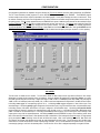
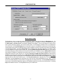
MIX SCREEN
The Mix screen is divided into two sections. The left section affects the Main Output and the right section affects the Zone Output.
Adjustments are made with the computer mouse (or keyboard). Levels are adjusted by dragging the corresponding ‘faders’ up or down.
Each fader provides thirty-two volume steps. Output level range is -70dB~+11dB in ≈1.4dB steps (bottom step ≈40dB). Mic level range is
-66dB~+11dB in ≈1.2dB steps (bottom step ≈42dB). Mic 1 & Mic 2 each have independent level adjustment to the Main & Zone Outputs.
Left-clicking mute toggles the corresponding signal off & on. Left-clicking enable toggles assignment of that mic/line input to the
associated output. Left-clicking priority toggles assignment of which mic/line input (if any) will override the other, at the associated output.
Left-clicking Channel 1~5 selects which Stereo Line Input is assigned to the associated output. Left-clicking ch.5 override allowed
toggles enabling of Channel 5 Override to the associated output (see Override on pg. 3). Left-clicking Preset A~D or E~H selects which
preset is recalled for the associated output. Left-clicking Preset Store provides a pop-up menu for storing the current settings at that
output section to any of the four associated presets. Left-clicking combine causes the SPM522D to enter a ‘room combining’ mode, where
Main & Zone sections both recall Preset D, and adjustments made to either Main or Zone settings will affect both outputs. All eight presets
(A~H) are available in ‘room combining’ mode, and each will affect both outputs. When ‘room combining’ is turned off, Main Preset A &
Zone Preset E are recalled, and adjustments can again be made independently for each output. The title bar at the top of the Mix screen
shows Device #, custom Device Name, & model of product being controlled. The PC Control Software can operate ‘off-line’ (no product
connected) by opening a ‘new’ file for the desired product. The Device # for ‘off-line’ files is assigned sequentially as a negative number.
7
CONFIGURATION
TONE and BALANCE SCREENS
Tone and Balance screens are available for all five Stereo Line Inputs. They are accessed through the Configure SPM522D drop-down
menu (or by right-clicking on the Mix screen). Also, double-clicking on a Channel (1~5), within the Mix screen, will simutaneously select
that channel and open its specific Tone and Balance screen. Tone and Balance screens allow each of the Stereo Line Input channels to
have its own Treble, Bass, and Balance settings for the Main & Zone Outputs independently. Tone and Balance settings for each Stereo
Line Input are stored in non-volatile memory, and are automatically recalled whenever that Stereo Line Input is selected for the associated
output. Tone and Balance screens are divided into two sections. The left section affects the Main Output and the right section affects the
Zone Output. Adjustments are made by dragging the corresponding ‘faders’. Settings are immediately stored in memory whenever any
adjustment is made. Treble has a gain range of ±12dB @ 15kHz, adjustable in 2dB steps. Bass has a gain range of ±12dB @ 50Hz,
adjustable in 2dB steps. Balance has a shift range of 48dB, adjustable in 2dB steps. Left-clicking Close will return you to the Mix screen.
8
CONFIGURATION
BUTTON DEFINITION SCREEN
®
The Button Definition screen is used to assign specific ‘actions’ to remote control buttons. ADVANTAGE infrared & wall-mount remote
controls have twenty-eight buttons. However, the SPM522D supports twelve additional buttons, which are only available when using
Remote Interface Kit or RS-232 control (see Remote Controls on pg. 5 & Computer Control on pg. 15). From the factory, the SPM522D is
programmed as follows: Buttons 1~12 provide volume up, volume down, & mute actions for Mic 1, Mic 2, Zone Output, & Main Output;
Buttons 13~28 provide preset & channel select actions for Zone Output & Main Output; Buttons 29~40 provide no defined actions.
However, using the Button Definition screen, each button may be assigned various, different actions (button definition). There are eight
types of actions available for both the Main & Zone Outputs. Each action type allows the selection of a more specific action. A button may
have one of each type of action assigned to it, thereby performing multiple functions. A button may also be assigned no actions at all,
thereby making that button inoperable. This is an effective way of limiting user access to certain settings or functions. Left-clicking a
Remote Control Button will select that button to be defined. Left-clicking on a particular type of Main or Zone action will then open a
drop-down menu of the specific actions (of that type) which are available for the associated output. Left-clicking the desired action will then
assign that action to the currently selected button. Preset Actions includes various store, recall, & combine actions. NOTE: Preset
Actions called ‘temp’ use the current settings for that output as a temporary preset, which will allow those settings to be restored later.
Program Select includes various channel select, override, & enable mic actions. NOTE: Program Select actions called ‘enable Mic’ will
also affect the ‘page-over’ ducking functions of that mic, at that output. Program Volume includes various volume, mute, duck, & balance
actions. CAUTION: Program Volume actions affect the VCA which controls only the Stereo Line Input signals. This VCA also provides the
‘page-over’ ducking functions for Mic 1 & Mic 2, as well as a ‘ramp’ function for Override (see Front & Rear Panel Features on pgs. 2 & 3).
To avoid conflicts, do not use Program Volume actions simultaneously with ‘page-over’ ducking or Override functions, at the same output.
Program Bass & Program Treble include cut, boost, & flat actions. Mic 1 Volume, Mic 2 Volume, & Output Volume include various
volume & mute actions. Multiple actions may be assigned to a single button. Likewise, a particular action may be assigned to multiple
buttons. To un-assign a particular action from a button, left-click on the blank space at the top of the drop-down menu for that type action.
Left-clicking Clear opens a pop-up menu, which allows button definitions (actions) to be cleared from the selected button, or from all
buttons. Left-clicking Default opens a pop-up menu, which allows button definitions (actions) to be set back to the factory default for the
selected button, or for all buttons. Left-clicking Remote Configuration opens the Remote Port Configuration screen (see next page).
Left-clicking Help provides additional instruction. Left-clicking Close will return you to the Mix screen. Factory default button definitions
are those described for standard remote controls (see Remote Controls on pgs. 4 & 5). When a button is selected, its Equivalent ASCII
Character appears on the screen. ASCII characters can be used via RS-232 to emulate control buttons (see Computer Control on pg. 15).
9
CONFIGURATION
REMOTE PORT CONFIGURATION SCREEN
The Remote Port Configuration screen is accessed by opening the Button Definition screen and left-clicking on Remote Configuration.
The Remote Port Configuration screen determines which types of actions will be recognized by each of the three possible remote control
inputs on the SPM522D (see Button Definition on previous page). Remote 1 & Remote 2 refer to the corresponding terminals on the rear
panel of the SPM522D (see Front & Rear Panel Features on pg. 3). Remote Translator and Front Panel refers to the rear panel
Translator terminals, and the front panel Internal Infrared Receiver (see Front & Rear Panel Features on pg. 2), which are treated as if they
were a single remote control input. The Remote Port Configuration screen allows the SPM522D to be customized, with regards to which
functions can be controlled from different locations. For example: When the SPM522D is used in an application with two separate rooms,
a remote control can be provided for each room, which has control of functions affecting only that room. Main actions could be assigned
only to Remote 1, with Zone actions assigned only to Remote 2. Remote Translator and Front Panel could then be assigned ‘universal’
control of all actions, or no control access at all. Another example: When the SPM522D is used in an application having a central control
location and a subordinate control location, ‘system-wide’ functions can be controlled from the central location, while only restricted control
is allowed from the subordinate location. All Preset actions could be assigned to Remote 1, for system configuration from the central
location. Zone Program Select actions could be assigned to Remote 2, for stereo source selection within the subordinate location. All
other actions could be un-assigned, thereby limiting user access. Left-clicking on on a certain type action, for a particular remote control
input, will toggle that assignment on & off. Left-clicking Restore Defaults re-assigns ‘universal’ control of all actions from all remote control
inputs (factory default). Left-clicking Help provides additional instruction. Left-clicking Close will return you to the Button Definition screen.
10
CONFIGURATION
MISCELLANEOUS SCREEN
The Miscellaneous screen is accessed by opening the Configuration Options screen and left-clicking the Miscellaneous tab. The
Miscellaneous screen is used to select options which customize the operation of the SPM522D. At the top of the Miscellaneous screen,
the Serial Number and Firmware Version of the particular SPM522D will be displayed. The PC Control Software can operate ‘off-line’
(with no product connected) by opening a ‘new’ file for the desired product. The Serial Number & Firmware Version are not displayed for
‘new’ (off-line) files. Left-clicking Device Name allows a custom name to be given to the SPM522D, by entering up to 30 characters of text.
The Device Name will be stored in the SPM522D memory, and will be displayed on the title bar of the Mix screen whenever that SPM522D
is accessed with the software. Left-clicking device number opens a drop-down menu which allows assignment of an ‘address’ number
(1~8) to the SPM522D, for computer control of multiple units. Left-clicking Disable front panel setup mode toggles off & on the ability to
access Setup Mode (but not Factory Defaults) via the front panel Setup button (see Setup/Options on pg. 6). Power-up status determines
what settings the SPM522D will automatically recall whenever power is turned on. From the factory, the SPM522D is set to recall the
settings which existed prior to power being shut off. Left-clicking recall preset A for Main and preset E for Zone will instead cause the
SPM522D to recall these specific presets at power-up. Main page-over ducking and Zone page-over ducking determine the amount of
attenuation applied to Stereo Line Input signals, and how quickly they return to normal level, when ducking is triggered via Mic 1 & Mic 2
page-over (see Front & Rear Panel Features on pg. 2). Left-clicking duck amount opens a drop-down menu of 41 attenuation choices
(0dB~80dB). Left-clicking ramp rate opens a drop-down menu of 256 return rate choices (0dB~200dB per second). NOTE: A mic/line
input must be enabled (assigned) to an output before it can trigger page-over ducking at that output. Left-clicking Restore Defaults opens
a pop-up menu, which allows the Miscellaneous options (or all Configuration Options) to be set back to their factory defaults. Left-clicking
Help provides additional instruction. Left-clicking Close will return you to the Mix screen.
11
CONFIGURATION
MUTE 1 / MIC 1 SCREEN
The Mute 1 / Mic 1 screen is accessed by opening the Configuration Options screen and left-clicking the Mute 1 / Mic 1 tab. The Mute 1 /
Mic 1 screen is used to select options which customize the function of the Mic 1 Mute terminal (see Front & Rear Panel Features on pg. 2).
Left-clicking Mute 1 input causes gated operation of Mic 1 toggles assignment of gating to the Mic 1 signal. Gating allows that mic/line
input signal to remain off, until triggered on either manually (via contact-closure) or automatically (via signal present) at the Mute 1 terminal.
Left-clicking Mute 1 input causes page-over duck of Main program source toggles assignment of ducking at the Main Output.
Left-clicking Mute 1 input causes page-over duck of Zone program source toggles assignment of ducking at the Zone Output.
Ducking is a temporary attenuation of the Stereo Line Input signal at that output, which is triggered manually (via contact-closure) or
automatically (via signal present) at the Mute 1 terminal. NOTE: A mic/line input must be enabled (assigned) to an output before it can
trigger page-over ducking at that output. Left-clicking Mute 1 Hold time opens a drop-down menu of 256 hold time choices (0~63.75
seconds). NOTE: Hold Time determines how long mute functions remain in effect after triggering (manual or automatic) is released. Hold
Time is not the same as Ramp Rate, which determines how fast a signal returns to normal after Hold Time has elapsed. Left-clicking
Mute 1 behaves like a programmable logic input will disable the Mute 1 functions described above, and instead allow the Mic 1 Mute
terminal to be used as a logic input, which can then be programmed like a remote control button (see Configuration on pg. 9). However, a
logic input can have two ‘button definitions’, one for when the circuit is ‘closed’ (activated) and another for when the circuit is ‘opened’
(released). Therefore, drop-down menus of the forty possible control buttons are provided for both the ‘closing’ & the ‘opening’ of the logic
input circuit. The logic input can still be triggered manually (via contact-closure) or automatically (via signal present). Left-clicking
Restore Defaults opens a pop-up menu, which allows the Mute 1 / Mic 1 options (or all Configuration Options) to be set back to their
factory defaults. Left-clicking Help provides additional instruction. Left-clicking Close will return you to the Mix screen.
12
CONFIGURATION
MUTE 2 / MIC 2 SCREEN
The Mute 2 / Mic 2 screen provides the same functions as the Mute 1 / Mic 1 screen, except that it affects the Mic 2 Mute terminal instead.
The Mute 2 / Mic 2 screen is accessed by opening the Configuration Options screen and left-clicking the Mute 2 / Mic 2 tab. The Mute 2 /
Mic 2 screen is used to select options which customize the function of the Mic 2 Mute terminal (see Front & Rear Panel Features on pg. 2).
Left-clicking Mute 2 input causes gated operation of Mic 2 toggles assignment of gating to the Mic 2 signal. Gating allows that mic/line
input signal to remain off, until triggered on either manually (via contact-closure) or automatically (via signal present) at the Mute 2 terminal.
Left-clicking Mute 2 input causes page-over duck of Main program source toggles assignment of ducking at the Main Output.
Left-clicking Mute 2 input causes page-over duck of Zone program source toggles assignment of ducking at the Zone Output.
Ducking is a temporary attenuation of the Stereo Line Input signal at that output, which is triggered manually (via contact-closure) or
automatically (via signal present) at the Mute 2 terminal. NOTE: A mic/line input must be enabled (assigned) to an output before it can
trigger page-over ducking at that output. Left-clicking Mute 2 Hold time opens a drop-down menu of 256 hold time choices (0~63.75
seconds). NOTE: Hold Time determines how long mute functions remain in effect after triggering (manual or automatic) is released. Hold
Time is not the same as Ramp Rate, which determines how fast a signal returns to normal after Hold Time has elapsed. Left-clicking
Mute 2 behaves like a programmable logic input will disable the Mute 2 functions described above, and instead allow the Mic 2 Mute
terminal to be used as a logic input, which can then be programmed like a remote control button (see Configuration on pg. 9). However, a
logic input can have two ‘button definitions’, one for when the circuit is ‘closed’ (activated) and another for when the circuit is ‘opened’
(released). Therefore, drop-down menus of the forty possible control buttons are provided for both the ‘closing’ & the ‘opening’ of the logic
input circuit. The logic input can still be triggered manually (via contact-closure) or automatically (via signal present). Left-clicking
Restore Defaults opens a pop-up menu, which allows the Mute 2 / Mic 2 options (or all Configuration Options) to be set back to their
factory defaults. Left-clicking Help provides additional instruction. Left-clicking Close will return you to the Mix screen.
13
CONFIGURATION
CHANNEL 5 OVERRIDE SCREEN
The Channel 5 Override screen is accessed by opening the Configuration Options screen and left-clicking the Channel 5 Override tab.
The Channel 5 Override screen is used to select options which customize the function of the Override terminal (see Front & Rear Panel
Features on pg. 3). When Channel 5 Override is released, the previously selected Stereo Line Input for each output will again be selected.
However, these signals will initially be attenuated, and will then return to their normal levels as determined by the following parameters.
Left-clicking Main duck amount or Zone duck amount opens a drop-down menu of 41 attenuation choices (0dB~80dB) for the stereo line
input signal at the associated output. Left-clicking Main duck ramp rate or Zone duck ramp rate opens a drop-down menu of 256 return
rate choices (0dB~200dB per second) for the stereo line input signal at the associated output. Left-clicking Override Hold time opens a
drop-down menu of 256 hold time choices (0~63.75 seconds). NOTE: Hold Time determines how long override remains in effect after
triggering (manual or automatic) is released. Hold Time is not the same as Ramp Rate, which determines how fast a signal returns to
normal after Hold Time has elapsed. Left-clicking Ch.5 Override input behaves like a programmable logic input will disable the
Channel 5 Override functions described above, and instead allow the Override terminal to be used as a logic input, which can then be
programmed like a remote control button (see Configuration on pg. 9). However, a logic input can have two ‘button definitions’, one for
when the circuit is ‘closed’ (activated) and another for when the circuit is ‘opened’ (released). Therefore, drop-down menus of the forty
possible control buttons are provided for both the ‘closing’ & the ‘opening’ of the logic input circuit. The logic input can still be triggered
manually (via contact-closure) or automatically (via signal present). Left-clicking Restore Defaults opens a pop-up menu, which allows the
Channel 5 Override options (or all Configuration Options) to be set back to their factory defaults. Left-clicking Help provides additional
instruction. Left-clicking Close will return you to the Mix screen.
14
COMPUTER CONTROL
The SPM522D has an RS-232 compatible serial interface, which allows it to be controlled by a computer (see Rear Panel Features on
page 3). In addition to the PC Control Software, the SPM522D offers two other methods of computer control.
Control Button Emulation: This method allows the computer to emulate the operation of the infrared transmitter or wall-mount control
panel. Using this method, the computer outputs ASCII characters, which are equivalent to the commands generated by the standard
control buttons. The SPM522D is unable to tell whether these commands come from the computer or from a standard control. However,
Control Button Emulation allows the computer to utilize up to forty button definitions (unlike standard controls, which have only twenty-eight
buttons). When using up to four SPM522Ds in a system, Control Button Emulation also allows the computer to designate which device or
devices should react to each control button command.
Advanced Computer Control: This method provides advanced commands, which allow the computer to retrieve or edit preset mixes,
retrieve or edit control button definitions, perform preset & volume actions, and a variety of other functions. The computer may also
emulate control buttons. Using this method, the computer may designate up to eight devices, and may create unlimited preset mixes and
control button definitions. The computer may also provide "real-time" display of various settings.
This manual only describes the Control Button Emulation method of computer control. For complete details about using the SPM522D with
a computer, including Advanced Computer Control, contact Biamp Systems for manual "Computer Control of SPM522D".
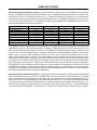
Each control button on the infrared transmitter or the wall-mount control panel corresponds to one character in the standard ASCII
character set. The character equivalents are summarized in the following table. This table includes all forty of the possible buttons, their
button numbers, their ASCII code equivalents, and their factory default button definitions (functions).
button 01
button 02
button 03
button 04
button 05
button 06
button 07
button 08
button 09
button 10
button 11
button 12
button 13
button 14
B
C
D
E
F
G
H
I
J
K
L
M
N
O
Volume Down Mic 1
Volume Down Mic 2
Volume Down Zone
Volume Down Main
Volume Up Mic 1
Volume Up Mic 2
Volume Up Zone
Volume Up Main
Toggle Mute Mic 1
Toggle Mute Mic 2
Toggle Mute Zone
Toggle Mute Main
Recall Zone Preset E
Recall Zone Preset F
button 15 P Recall Zone Preset G
button 16 Q Select Channel 5 Zone
button 17 R Select Channel 1 Zone
button 18 S Select Channel 2 Zone
button 19 T Select Channel 3 Zone
button 20 U Select Channel 4 Zone
button 21 V Recall Main Preset A
button 22 W Recall Main Preset B
button 23 X Recall Main Preset C
button 24 Y Select Channel 5 Main
button 25 Z Select Channel 1 Main
button 26 [ Select Channel 2 Main
button 27 \ Select Channel 3 Main
button 28 ] Select Channel 4 Main
button 29
button 30
button 31
button 32
button 33
button 34
button 35
button 36
button 37
button 38
button 39
button 40
^
_
'
b
c
d
e
f
g
h
i
j
no button definition assigned
no button definition assigned
no button definition assigned
no button definition assigned
no button definition assigned
no button definition assigned
no button definition assigned
no button definition assigned
no button definition assigned
no button definition assigned
no button definition assigned
no button definition assigned
When a control button is first pressed, the SPM522D receives the character which corresponds to that button. If the control button is
pressed longer than 110 milliseconds, the SPM522D receives a "repeat code", indicating the control button is still being pressed. The
SPM522D continues to receive the repeat code (approximately nine times per second) until the control button is released. The ASCII
character which corresponds to the repeat code is @ (the "commercial at" sign).
The "receive data" (RxD) signal at the SPM522D Serial Port is combined with signals from any standard controls, before being sent to the
main microprocessor. The computer can initiate any functions or actions that a standard control can, by simply transmitting the equivalent
control button ASCII character. When interfacing the SPM522D to a computer, the computer must be aware that the SPM522D will "echo"
all characters it receives (both from computer and standard controls) via the Serial Port 'transmit data' (TXD) signal.
Up to four SPM522Ds may be connected together, and addressed individually, when using Control Button Emulation. When multiple units
are used, each unit should be assigned a unique "Device Number" (see Configuration on pg. 11). Normally, all of the SPM522Ds would
react to control button commands. However, the computer can send commands to specific units, by preceding each command with a
"device select prefix" character (see following table). Only those SPM522Ds whose Device Numbers are specified will respond to the
command which follows. Those specific devices will also react to any repeat codes which immediately follow the command. If a command
is not immediately preceded by a device select prefix character, then all SPM522Ds in the system will react to that command.
Select Device 1
Select Device 2
Select Devices 1 & 2
Select Device 3
Select Devices 1 & 3
l
m
n
o
p
Select Devices 2 & 3
Select Devices 1 & 2 & 3
Select Device 4
Select Devices 1 & 4
Select Devices 2 & 4
15
q
r
s
t
u
Select Devices 1 & 2 & 4
Select Devices 3 & 4
Select Devices 1 & 3 & 4
Select Devices 2 & 3 & 4
Select Devices 1 & 2 & 3 & 4
v
w
x
y
z
COMPUTER CONTROL
Serial Interface Electrical Connections & Cabling: The 9-pin Subminiature D (male) connector on the SPM522D rear panel provides
the RS-232 compatible serial interface signals used for computer control. The SPM522D transmits serial data on pin 3 (TxD) and receives
serial data on pin 2 (RxD). The serial interface ground is on Pin 5. The DTR & RTS signals are connected to the +12 Volt power supply
(each through its own resistor) and are always asserted when the SPM522D power is on. Most IBM compatible PCs use either 25-pin or 9pin (male) connectors for their serial ports. The following table summarizes the pin assignments for the SPM522D serial interface, and for
the standard IBM compatible 9-pin and 25-pin serial ports.
SIGNAL NAME
CD (carrier detect)
RxD (receive data)
TxD (transmit data)
DTR (data terminal ready)
signal ground
DSR (data set ready)
RTS (request to send)
CTS (clear to send)
RI (ring indicator)
DIRECTION
input
input
output
output
n/a
input
output
input
input
SPM522D 9-PIN
n/a
pin 2
pin 3
pin 4
pin 5
n/a
pin 7
n/a
n/a
IBM-PC 9-PIN
pin 1
pin 2
pin 3
pin 4
pin 5
pin 6
pin 7
pin 8
pin 9
IBM-PC 25-PIN
pin 8
pin 3
pin 2
pin 20
pin 7
pin 6
pin 4
pin 5
pin 22
The SPM522D only requires receive data (pin 2), transmit data (pin 3), and signal ground (pin 5) to be connected for successful data
communications. However, the PC may require that signals be present on the data set ready, clear to send, or carrier detect inputs, as
well as the receive data, transmit data, and signal ground pins. The diagrams on the following page show cables for interfacing to a PC
with either a 9-pin or a 25-pin serial port connector. In most cases, one or the other of these cables will work. However, success or failure
depends entirely on the actual computer hardware and software being used. When trying to solve an interfacing problem, the most
important thing to remember is that an output of one device should connect to one or more inputs of the other device, and that two outputs
should never be connected together. Also, keep in mind that the RS-232 specification calls for the cable length to be no greater than 50
feet (although it is not unusual to be able to operate over distances of 150 to 250 feet), and the connectors must be of the appropriate
gender (male or female) to mate properly. For best results, a shielded cable should be used, with the shield connected to signal ground.
Since the SPM522D serial interface ground is also tied (indirectly) to the analog signal ground, undesirable ground loops may occur when
the SPM522D is connected to a PC (if the system grounding is not carefully designed). For best performance, the PC ground and the
chassis ground of the SPM522D should be at the same potential, and the PC should get AC power from the same source as the SPM522D
(and any other audio equipment which is connected to the SPM522D).
Serial Interface Data Communications Parameters: The SPM522D communicates through the serial interface at a rate of 9600 bits per
second, with 8 data bits, 1 stop bit, and no parity. The SPM522D utilizes a subset of the standard 7-bit ASCII character set. The eighth
data bit of each character (the most significant bit) should always be 0. The computer should not echo the characters it receives. The
computer should not be set for either hardware (DTR) or software (XON/XOFF) flow control. The baud rate may be changed to 2400 bits
per second by means of an internal DIP switch labelled ‘Opt. W’ (for access instructions and switch diagram see Options on pg. 6). The
‘Opt. W’ DIP switch is located on the right-center of the lower circuit board, adjacent to the microprocessor (U2). To select 2400 baud rate:
1) Disconnect power from the SPM522D. 2) Remove top panel. 3) Move ‘Opt. W’ DIP switch towards the rear panel, to the ‘off’ position.
16
COMPUTER CONTROL
SPM522D to PC 9-Pin Connector
9-pin
SPM522D male
n/a
RxD
TxD
DTR
ground
n/a
RTS
n/a
n/a
female
1
2
3
4
5
6
7
8
9
1
2
3
4
5
6
7
8
9
n/a
RxD
TxD
DTR
ground
n/a
RTS
n/a
n/a
female
1
2
3
4
5
6
7
8
9
1
2
3
4
5
6
7
8
9
1
2
3
4
5
6
7
8
9
#4
9-pin
n/a
RxD
TxD
DTR
ground
n/a
RTS
n/a
n/a
#3
1
2
3
4
5
6
7
8
9
These connections
may not be required:
DTR to CD;
DTR to DSR;
or RTS to CTS.
female
1
2
3
4
5
6
7
8
9
SPM522D male
(shield)
Four SPM522Ds Connected to a PC
9-pin
SPM522D male
n/a
RxD
TxD
DTR
ground
n/a
RTS
n/a
n/a
These connections
may not be required:
DTR to CD;
DTR to DSR;
or RTS to CTS.
SPM522D to PC 25-Pin Connector
9-pin
SPM522D male
(shield)
female
1
2
3
4
5
6
7
8
9
9-pin
SPM522D male
n/a
RxD
TxD
DTR
ground
n/a
RTS
n/a
n/a
female
1
2
3
4
5
6
7
8
9
1
2
3
4
5
6
7
8
9
#1
9-pin
SPM522D male
n/a
RxD
TxD
DTR
ground
n/a
RTS
n/a
n/a
1
2
3
4
5
6
7
8
9
#2
17
9-pin
female
male
1
2
3
4
5
6
7
8
9
1
2
3
4
5
6
7
8
9
25-pin
female
male
8
3
2
20
7
6
4
5
22
8
3
2
20
7
6
4
5
22
9-pin
female
male
1
2
3
4
5
6
7
8
9
1
2
3
4
5
6
7
8
9
PC
CD
RxD
TxD
DTR
ground
DSR
RTS
CTS
RI
PC
CD
RxD
TxD
DTR
ground
DSR
RTS
CTS
RI
PC
CD
RxD
TxD
DTR
ground
DSR
RTS
CTS
RI
These connections
may not be required:
DTR to CD;
DTR to DSR;
or RTS to CTS.
female
1
2
3
4
5
6
7
8
9
When connecting
four SPM522Ds to a
PC 25-pin connector,
refer to "SPM522D to
PC 25-pin connector"
diagram above for
pin assignments.
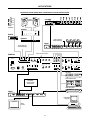
APPLICATIONS
Retail Bookstore plus Music Department with Paging and Remote Control
music dept.
foreground
music
system
bookstore
background
music
system
CPA650
CPA130
ADVANTAGE
ADVANTAGE
peak
peak
1
2
CPA 650
peak
peak
1
2
CPA 130
Commercial Power Amplifier
Commercial Power Amplifier
level
level
25
boost/cut
12 dB
in
40
63
100
160
level
level
micro
EQ152
6 dB
12dB
6dB
peak
out
music dept.
paging
mic
250
bookstore
paging
mic
micro
EQ152
400
630
1K
1.6K
2.5K
4K
6.3K
boost
10K
16K
25
40
63
100
160
250
400
630
1K
1.6K
2.5K
4K
6.3K
10K
16K
gain
boost/cut
12 dB
boost
boost
0
cut
cut
channel A
channel B
A
B
25
boost/cut
12 dB
microEQ152
6 dB
12dB
6dB
peak
out
0
0
cut
6 dB
12dB
6dB
peak
out
in
40
63
100
160
250
400
630
1K
1.6K
2.5K
4K
6.3K
10K
16K
boost
25
40
63
100
160
250
400
630
1K
1.6K
2.5K
4K
6.3K
10K
16K
gain
boost/cut
12 dB
boost
boost
0
cut
cut
channel A
microEQ152
6 dB
12dB
6dB
peak
out
0
0
cut
in
A
channel B
B
in
SPM522D
outputs
BIAMP SYSTEMS
Portland, Oregon
L
R
an affiliate of
Rauland-Borg Corp.
zone
limit
L
R
main
limit
zone
main
3
2
1
level
level
level
pad
limit
0
10
0
10
2
IR2
IR3
gnd
gnd
mic 1
signal present
mute
on
R
limit
3
override
sensitivity
5
4
2
+10
1
level
level
mic input
10
0
10
0
mic 2
patch
4
5
R
0
remote display
phtm
power
inputs
1
DC
out
10
main out
gnd
sig pres
zone out
27 VAC
18W max
IR2
IR3
gnd
low
high
override
MADE IN U.S.A.
trim
0dB
30dB
0
serial port
mic 1
patch
L
stereo
mono
L R
L
pad
trim
phtm
power
mic 2
signal present
mute
0dB
30dB
on
10
+10
remote
translator
override
mic input
override
CD player #1
COMPACT
1
0:00
DIGITAL AUDIO
customized control panel
(Remote Interface Kit plus
momentary push-buttons)
music dept. sources
(remote control of
source selection)
CD player #2
COMPACT
2
DIGITAL AUDIO
2:50
cassette tape deck
MUSIC DEPARTMENT
SOURCE
CD-1
CD-2
TAPE
satellite music service
VOL
VOLUME
VOL
MUTE
bookstore sources
(satellite music with
message repeater
automatic override)
18
CHANNEL 5
digital message repeater
APPLICATIONS
Two Hotel Meeting Rooms with Room Combining and Remote Control
room #2 microphones
room #2
ceiling
speakers*
301e
room #1
ceiling
speakers*
DT-1A DT-1A
xfmr
xfmr
BIAMP SYSTEMS
pad
pad
Portland, Oregon
27 VAC
18W
pad
an affiliate of
Rauland-Borg Corp.
in
out
com
patch
MADE IN U.S.A.
+ --
+10V C gnd com
main output
remote
+ --
com
stack input
+
--
com
600
mic/line 3
CPA650
+
--
+
com
/ ch. 2
--
mic/line 1
room #1 microphones
ADVANTAGE
peak
CPA 650
peak
1
2
level
level
Commercial Power Amplifier
301e
BIAMP SYSTEMS
pad
pad
Portland, Oregon
pad
an affiliate of
Rauland-Borg Corp.
27 VAC
18W
in
patch
MADE IN U.S.A.
EQ282M
out
com
+ --
+10V C gnd com
main output
remote
+ --
com
stack input
+
--
com
600
mic/line 3
+
--
com
/ ch. 2
+
--
mic/line 1
ADVANTAGE EQ282M
Digitally Controlled EQ
1
2
3
4
preset clear
select
1
2
channel
select
Error
IR
on
*main out & zone out
set for mono
SPM522D
outputs
BIAMP SYSTEMS
Portland, Oregon
L
R
an affiliate of
Rauland-Borg Corp.
zone
limit
L
R
main
limit
zone
main
3
2
1
level
level
level
mic 1
patch
L
pad
0
limit
10
0
10
2
IR2
IR3
gnd
gnd
remote display
mic 1
signal present
mute
on
R
limit
3
override
sensitivity
2
5
4
+10
1
level
level
mic input
10
0
10
0
mic 2
patch
4
5
R
0
DC
out
0
phtm
power
inputs
1
serial port
10
main out
gnd
sig pres
zone out
27 VAC
18W max
IR2
IR3
gnd
low
high
override
MADE IN U.S.A.
trim
0dB
30dB
stereo
mono
L R
pad
trim
0dB
30dB
L
phtm
power
mic 2
signal present
mute
on
10
+10
remote
override
translator
mic input
override
satellite music service
CHANNEL 5
Remote
Display
Controller
AM/FM tuner
3
FM
101.9
remote control selection of presets
affects room combining (SPM522D)
and room equalization (EQ282M)
MAIN
ZONE
MIC 2
MIC 1
VOL
VOL
VOL
VOL
VOL
VOL
VOL
VOL
MUTE
H 5
G
MUTE
preset
MUTE
4
D 5
4
3
C
2 ZONE 3
F
E
MUTE
4
SPM 522D
4
D 5
H 5
MUTE
VOL
1
3
C
G
E F G H
zone
main
1 2 3 4 5
mute
1
channel
2
mic
1 2 3 4 5
2
main
min
preset
MAIN
preset
preset
zone
2
B
preset
MAIN
max
main
A B C D
2 ZONE 3
2
MUTE
1
F
VOL
MAIN
VOL
A
IR receiver
1
MUTE
A
E
VOL
1
MUTE
VOL
VOL
ZONE
2
mic
1
VOL
1
channel
1 2 3 4 5
MIC 2
1 2 3 4 5
mute
VOL
main
min
preset
E F G H
zone
main
room #2 display panel
with infrared receiver
MIC 1
zone
main
A B C D
B
max
SPM 522D
room #1 display panel
with infrared receiver
IR receiver
1
2
zone
zone
SPM522D Remote Display Panel
SPM522D Remote Display Panel
19
APPLICATIONS
Restaurant plus Bar with Paging and Remote Control
lounge
stereo
speaker
system
restaurant
ceiling
speaker
system*
lounge only
paging
mic
CPA130
ADVANTAGE
peak
peak
1
2
CPA 130
Commercial Power Amplifier
level
level
D60EQ
+15
+15
0
micro
EQ152
40
63
100
160
250
400
630
1K
1.6K
2.5K
4K
6.3K
10K
16K
boost
25
40
63
100
160
250
400
630
1K
1.6K
2.5K
4K
6.3K
10K
16K
gain
250
500
1K
2K
4K
8K
restaurant & lounge
priority paging
mic
ADVANTAGE D60EQ
Amplifier/Equalizer
16K
boost/cut
12 dB
boost
boost
0
cut
cut
channel A
channel B
microEQ152
6 dB
12dB
6dB
peak
out
0
0
cut
A
B
in
*main out set for mono
SPM522D
outputs
BIAMP SYSTEMS
Portland, Oregon
L
R
an affiliate of
Rauland-Borg Corp.
zone
limit
L
R
main
limit
zone
main
3
2
1
level
level
level
mic 1
patch
L
pad
0
limit
10
0
10
2
IR2
IR3
gnd
gnd
remote display
mic 1
signal present
mute
on
R
limit
3
override
sensitivity
5
4
2
+10
1
level
level
mic input
10
0
10
0
mic 2
patch
4
5
R
0
DC
out
0
phtm
power
inputs
1
serial port
10
main out
gnd
sig pres
zone out
27 VAC
18W max
IR2
IR3
gnd
low
high
override
MADE IN U.S.A.
trim
0dB
30dB
stereo
mono
L R
pad
trim
0dB
30dB
L
phtm
power
mic 2
signal present
mute
on
10
+10
remote
override
translator
mic input
override
satellite music service
CHANNEL 5
juke box relay wired
for manual override
in lounge area only
Remote
Display
Controller
lounge juke box
A1 A2 A3 A4 A5 A6 A7
B1 B2 B3 B4 B5 B6 B7
remote control selection of presets
affects volume & paging settings
for alternate usage of rooms
MAIN
VOL
ZONE
F
MIC 2
2 ZONE 3
MIC 1
B
1
VOL
VOL
A
VOL
VOL
max
2
VOL
VOL
IR receiver
SPM 522D
MAIN
1
E
MUTE
VOL
H 5
MUTE
G
MUTE
preset
F
E
MUTE
4
2 ZONE 3
4
D 5
2
mic
1
VOL
channel
1 2 3 4 5
MUTE
1
1
1 2 3 4 5
mute
1
E F G H
zone
main
MAIN
3
SPM 522D
main
min
C
zone
main
A B C D
preset
max
preset
lounge wall-mount
control panel and
display panel
restaurant display panel
with infrared receiver
IR receiver
2
in
125
level
B
12 dB
peak
signal
present
on
-15
64
A
25
boost/cut
6 dB
12dB
6dB
peak
out
0
-15
preset
3
4
C
D 5
4
zone
main
main
A B C D
min
preset
preset
G
H 5
MUTE
MUTE
MUTE
VOL
VOL
VOL
E F G H
zone
main
1 2 3 4 5
zone
SPM522D Remote Display Panel
20
VOL
VOL
VOL
VOL
MIC 1
MIC 2
ZONE
MAIN
1
channel
2
mic
1 2 3 4 5
2
mute
1
2
zone
SPM522D Remote Display Panel
APPLICATIONS
Boardroom Sound System with Teleconference Feed & Remote Control
stereo
speakers
patch
8
patch
input
ON
7
patch
input
input
ON
6
patch
ON
5
input
input
ON
4
patch
patch
input
ON
input
ON
3
ON
2
pad
ungated
phantom
duck ch8
patch pre
outputs
patch
input
pad
ungated
phantom
duck ch8
patch pre
ON
pad
ungated
phantom
duck ch8
patch pre
patch
ON
pad
ungated
phantom
duck ch8
patch pre
expansion
main patch
stack in
pad
ungated
phantom
duck ch8
patch pre
logic
outputs
aux
pad
ungated
phantom
duck ch8
patch pre
main
an affiliate of
Rauland-Borg Corp.
pad
ungated
phantom
duck ch8
patch pre
Portland, Oregon
DC out
15 watts
class 2 wiring ±12VDC
pad
ungated
phantom
aux off
patch pre
BIAMP SYSTEMS
~
27V
50/60 Hz
slave
-12db
hp filter
last mic
aux post
autoONE
ceiling
speakers*
CPA650
ADVANTAGE
+15
0
0
-15
peak
signal
present
on
500
1K
2K
4K
CPA 650
8K
level
ADVANTAGE D60EQ
Amplifier/Equalizer
EQ282/8
-15
250
2
level
+15
125
peak
1
Commercial Power Amplifier
D60EQ
64
peak
16K
level
preset
peak
peak
video output for
teleconferencing
ADVANTAGE EQ 282/8
Digitally Controlled EQ
preset
bypass
Channel 1
bypass
on
Channel 2
VSX41
audio output for
teleconferencing*
BIAMP SYSTEMS
ADVANTAGE VSX41
Portland, Oregon
Video Switcher
remote
translator
remote
output
remote 2
remote 1
output
input 4
input 3
input 2
input 1
an affiliate of
Rauland-Borg Corp.
logic inputs
gnd IR2 IR3 gnd low high gnd IR2 IR3 gnd IR2 IR3
*zone out set for mono
SPM522D
outputs
BIAMP SYSTEMS
Portland, Oregon
L
R
an affiliate of
Rauland-Borg Corp.
zone
limit
L
R
main
limit
zone
main
3
2
1
level
level
level
mic 1
patch
L
pad
0
limit
10
0
10
2
IR2
IR3
gnd
gnd
signal present
R
limit
3
override
sensitivity
5
4
level
level
2
+10
1
mic input
10
0
10
0
mic 2
patch
4
5
R
0
DC
out
0
mic 1
mute
on
inputs
1
serial port
10
main out
gnd
sig pres
zone out
27 VAC
18W max
IR2
IR3
gnd
low
high
override
MADE IN U.S.A.
phtm
power
trim
0dB
30dB
stereo
mono
L R
L
pad
phtm
power
trim
mic 2
signal present
mute
0dB
30dB
on
10
+10
remote display
remote
translator
override
mic input
override
CD player
COMPACT
1
DIGITAL AUDIO
audio cassette deck
'third-party'
remote control
touch screen
video tape player
VHS
VSX41
BIAMP SYSTEMS
ADVANTAGE VSX41
Portland, Oregon
Video Switcher
remote
output
remote
translator
remote 2
remote 1
output
input 4
input 3
input 2
input 1
an affiliate of
Rauland-Borg Corp.
logic inputs
gnd IR2 IR3 gnd low high gnd IR2 IR3 gnd IR2 IR3
multi-media
computer
video
monitor
21
2:50
1
Stereo Program Inputs
level
L
Stereo
Input 1
L
R
R
Stereo
Source 1
Stereo Inputs
L
R
R
Main Program
Volume Balance
Input 1
R
Main
EQ
Limiter
level
L
R
R
Stereo
Source 3
Zone Program
Volume Balance
Stereo
Input 4
L
R
R
R
Stereo
Source 4
Zone
EQ
Limiter
level
L
Zone
Output
*
Left
*
Right
mono
L
30dB
PAD
R
Stereo
Source 5
Volume to Main
Mic 1
Volume to Zone
out in
override sensitivity
Stereo
Source 5
Signal
Present
Volume to Main
Mic 2
Volume to Zone
20dB
PAD
* internal jumpers for
optional 20dB pad at
Main & Zone Outputs
22
Mono Mic/Line Inputs
CPU & Logic
Peak
+24V
Trim
(40 dB)
Mic 1
Phantom
Power
Channel 5
Override
Mic 1
Signal
Present
Signal
Detect
Mic 2 Mute
(Talkover)
30dB
PAD
Mic 1
Patch
Infrared
Receiver
Mic 1
Source
Trim
(40 dB)
Mic 2
Phantom
Power
30dB
PAD
Microprocessor
Remote 1
Peak
+24V
Non-Volatile
Memory
Mic 1 Mute
(Talkover)
Mic 2
Signal
Present
Signal
Detect
Remote 2
Remote
Translator
Mic 2
Patch
Mic 2
Source
Serial Port
(RS-232)
Internal Control
Signals to Digital
Potentiometers
and Switches, etc.
Remote
Control
Decoder
Front Panel
Display
Remote
Display
BLOCK DIAGRAM
R
Right
Limit
Threshold
out in
Stereo
Input 5
(Override
Channel)
*
Limit
Zone
Volume
L
level
L
Left
Limit
Threshold
bass treble
Zone Source
Selector
L
*
mono
Input 4
Input 5
Stereo
Input 3
Main
Output
Limit
Main
Volume
L
Input 3
Stereo
Source 2
bass treble
Main Source
Selector
Input 2
level
L
Stereo
Input 2
Program Source Selection & Outputs
SPECIFICATIONS
Frequency Response (20Hz-20kHz @ +4dBu):
+0/-2dB
Total Harmonic Distortion (20Hz-20kHz @ +4dBu):
< 0.05%
Output Noise (20Hz-20kHz @ nominal levels):
< -75dBu
Equivalent Input Noise (20Hz-20kHz, 150Ω termination @ Mic/Line Input):
-127dBu
Maximum Gain (Mic/Line Input to Main/Zone Outputs):
75dB
Input Trim Gain Range:
Mic/Line Inputs (30dB pad out)
+52dB to +14dB
Stereo Line Inputs (30dB pad out - Input 5)
+10dB to -50dB
Input Impedance:
2k ohms
Mic/Line Inputs (balanced)
5.4k ohms
Mic Patch (unbalanced)
Stereo Line Inputs (unbalanced)
7k ohms
Stereo Line Input 5 (30dB pad in)
20k ohms
Maximum Input:
Mic/Line Inputs (balanced)
+33dBu
Mic Patch (unbalanced)
+18dBu
Stereo Line Inputs (unbalanced)
+27dBu
+39.2dBu (70.7V)
Stereo Line Input 5 (30dB pad in)
Output Impedance:
Main Out (balanced)
100 ohms
Zone Out (balanced)
100 ohms
Mic Patch (unbalanced)
100 ohms
Maximum Output:
Main Out (balanced)
+24dBu
Zone Out (balanced)
+24dBu
Mic Patch (unbalanced)
+18dBu
Stereo Limiter Threshold Range (Main/Zone balanced):
+24dBu to +9dBu
Phantom Power (Mic/Line Inputs only):
+24 Volts DC
±12 Volts DC @ 20mA max.
DC Out:
Power Requirements:
10 Watts max.
Power Consumption:
110/240VAC 50/60Hz
Dimensions:
Height (1 rack space)
3.5 inches (89mm)
Width
19 inches (483mm)
Depth
7.5 inches (191mm)
8.5 lbs. (3.86kg)
Weight:
23
WARRANTY
BIAMP SYSTEMS IS PLEASED TO EXTEND THE FOLLOWING 5-YEAR
LIMITED WARRANTY TO THE ORIGINAL PURCHASER OF THE
PROFESSIONAL SOUND EQUIPMENT DESCRIBED IN THIS MANUAL.
BIAMP Systems expressly warrants this product to be
free from defects in material and workmanship for a
period of 5 YEARS from the date of purchase as a
new product from an authorized BIAMP Systems
dealer under the following conditions.
1. The Purchaser is responsible for completing and
mailing to BIAMP Systems, within 10 days of
purchase, the attached warranty application.
2. In the event the warranted BIAMP Systems product
requires service during the warranty period, BIAMP
Systems will repair or replace, at its option, defective
materials, provided you have identified yourself as the
original purchaser of the product to any authorized
BIAMP Systems Service Center. Transportation and
insurance charges to and from an authorized Service
Center or the BIAMP Systems factory for warranted
products or components thereof to obtain repairs shall
be the responsibility of the purchaser.
3. This warranty will be VOIDED if the serial number
has been removed or defaced; or if the product has
been subjected to accidental damage, abuse, rental
usage, alterations, or attempted repair by any person
not authorized by BIAMP Systems to make repairs; or
if the product has been installed contrary to BIAMP
Systems's recommendations.
4. Electro-mechanical fans, electrolytic capacitors,
and the normal wear and tear of appearance items
such as paint, knobs, handles, and covers are not
covered under this warranty.
5. BIAMP SYSTEMS SHALL NOT IN ANY EVENT BE
LIABLE
FOR
SPECIAL,
INCIDENTAL,
OR
CONSEQUENTIAL DAMAGES, INCLUDING LOST
PROFITS, LOSS OF USE, PROPERTY DAMAGE, INJURY
TO GOODWILL, OR OTHER ECONOMIC LOSS OF ANY
SORT. EXCEPT AS EXPRESSLY PROVIDED HEREIN,
BIAMP SYSTEMS DISCLAIMS ALL OTHER LIABILITY TO
PURCHASER OR ANY OTHER PERSONS ARISING OUT
OF USE OR PERFORMANCE OF THE PRODUCT,
INCLUDING LIABILITY FOR NEGLIGENCE OR STRICT
LIABILITY IN TORT.
6. THIS WARRANTY IS IN LIEU OF ALL OTHER
WARRANTIES EXPRESSED OR IMPLIED.
BIAMP
SYSTEMS EXPRESSLY DISCLAIMS ALL IMPLIED
WARRANTIES OF MERCHANTABILITY AND FITNESS
FOR A PARTICULAR PURPOSE. THE REMEDIES SET
FORTH HEREIN SHALL BE THE PURCHASER'S SOLE
AND EXCLUSIVE REMEDIES WITH RESPECT TO ANY
DEFECTIVE PRODUCT. THE AGENTS, EMPLOYEES,
DISTRIBUTORS, AND DEALERS OF BIAMP SYSTEMS
ARE NOT AUTHORIZED TO MODIFY THIS WARRANTY
OR TO MAKE ADDITIONAL WARRANTIES BINDING ON
BIAMP SYSTEMS.
ACCORDINGLY, ADDITIONAL
STATEMENTS SUCH AS DEALER ADVERTISEMENTS
OR REPRESENTATIONS DO NOT CONSTITUTE
WARRANTIES BY BIAMP SYSTEMS.
7. No action for breach of this warranty may be
commenced more than one year after the expiration of this
warranty.
Thank you for purchasing BIAMP SYSTEMS...
AMERICAN SOUND CRAFTSMANSHIP
Biamp Systems
10074 S.W. Arctic Drive
Beaverton, Oregon 97005
(503) 641-7287
http://www.biamp.com
585.0121.00