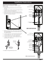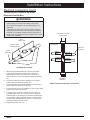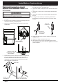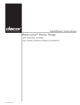
1
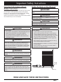
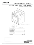
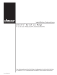
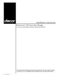
Installation Instructions
Renaissance ® Electric Range
with induction cooktop
Models: RR30NS, RR30NS-C, RR30NFS, RR30NFS-C, RR30NIS and RR30NIFS
Part No. 105910 Rev. A
Table of Contents
Important Safety Instructions...................................................... 1
Important Information About Safety Instructions......................... 1
Safety Symbols in this Manual....................................................1
General Safety Precautions......................................................... 2
Product Specifications.................................................................3
Electrical Requirements (Except models ending with -C)........... 3
Electrical Requirements (Models RR30NS-C, RR30NFS-C)...... 3
Product Dimensions.....................................................................4
Installation Specifications............................................................5
Cabinet Layout.............................................................................5
Installation Instructions................................................................8
Verify the Package Contents....................................................... 8
Installing the Anti-Tip Bracket...................................................... 8
Backguard Installation...............................................................10
Raised Vent Installation............................................................. 10
Removing the Oven Door.......................................................... 10
Electrical Connection.................................................................10
Installing the Range................................................................... 16
Re-installing the Oven Door...................................................... 16
Verifying Proper Operation........................................................ 17
IMPORTANT:
•
Installer: In the interest of safety and to minimize problems, read these installation instructions completely and carefully before you
begin the installation process. Leave these installation instructions with the customer.
•
Customer: Keep these installation instructions for future reference and the local building inspector’s use.
Customer Service Information
If You Need Help...
Product Data Label Location
If you have questions or problems with installation, contact your
Dacor dealer or the Dacor Customer Service Team. For repairs
to Dacor appliances under warranty call the Dacor Distinctive
Service line. Whenever you call, have the model and serial
number of the appliance ready. The model and serial number are
printed on the product data label.
The product data label can be seen through the grill below the
control panel, on the right side.
Product data label
(view through right side
of grate with flashlight)
Dacor Customer Service
Phone: (800) 793-0093, extension 2813 (U.S.A. and Canada)
Monday — Friday 6:00 a.m. to 5:00 p.m. Pacific Time
Web site: www.dacor.com
Dacor Distinctive Service (for repairs under warranty only)
Phone: (800) 793-0093, extension 2822 (U.S.A. and Canada)
Monday — Friday 6:00 a.m. to 5:00 p.m. Pacific Time
Model Identification
Model
Configuration*
Handle Type
RR30NS
Freestanding, (full size side panels),
6-inch backguard standard
Mounted on
outside of door
Power cord not included. Not for
installation in Canada.
RR30NS-C
Freestanding, (full size side panels),
6-inch backguard standard
Mounted on
outside of door
Cord connected, for installation in
Canada and U.S.A., where local
codes permit.
RR30NFS
Freestanding, (full size side panels),
Flush handle,
Power cord not included. Not for
6-inch backguard standard
integrated in door installation in Canada.
RR30NFS-C
Cord connected, for installation in
Freestanding, (full size side panels),
Flush handle,
Canada and U.S.A., where local
6-inch backguard standard
integrated in door
codes permit.
RR30NIS
Built-in/Slide-in (3” removable side
panels), backguard optional
RR30NIFS
Built-in/Slide-in (3” removable side
panels), backguard optional
Mounted on
outside of door
Electrical Connection**
Power cord not included. May be
installed in Canada and U.S.A.
Flush handle,
Power cord not included. May be
integrated in door installed in Canada and U.S.A.
* See page 4 for further details.
**See page 3 for further details.
All specifications subject to change without notice. Dacor® assumes no liability for changes to specifications.
© 2013 Dacor, all rights reserved.
Important Safety Instructions
Important Information About
Safety Instructions
The Important Safety Instructions and warnings in this manual
are not meant to cover all possible problems and conditions
that can occur. Use common sense and caution when installing,
maintaining or operating this or any other appliance.
Always contact the Dacor Customer Service Team about problems
and conditions that you do not understand.
Safety Symbols in this Manual
danger
Immediate hazards that WILL result in severe personal injury or
death.
warning
Hazards or unsafe practices that COULD result in severe
personal injury or death.
caution
Hazards or unsafe practices that COULD result in minor
personal injury or property damage.
danger
warning
For your safety:
Tip-over hazard:
•
•
A child or adult can tip the range and be killed.
•
Attach the anti-tip bracket to the floor or wall as directed
in these installation instructions. Engage the floor or wall
mounted anti-tip bracket by sliding the rear leg on the range
into it according to these installation instructions. Using
a flashlight, be sure that the anti-tip bracket engages the
range’s rear leg as shown below.
•
After moving the range, be sure to re-engage the rear leg
into the anti-tip bracket as shown below.
•
See the anti-tip bracket installation instructions in this guide
for further details.
•
Failure to follow these instructions can result in death or
serious burns to children or adults.
Do not store or use gasoline or other flammable vapors and
liquids in the vicinity of this or any other appliance.
•
Do not obstruct the flow of ventilation air to the unit.
•
Keep the area around the appliance clear and free from
combustible material.
warning
Persons with a pacemaker or other medical device should use
caution when standing near an induction cooktop when it is
in use. The electromagnetic field generated by an induction
cooktop may affect operation of a pacemaker or other medical
device. Consult your doctor or medical device manufacturer
about your particular situation.
warning
If the information in this manual is not followed exactly, a fire or
explosion may result causing property damage, personal injury
or death.
warning
NEVER use this appliance as a space heater to heat or warm
the room. Doing so may result in overheating of the appliance.
warning
NEVER cover any slots, holes or passages in the oven bottom
or cover an entire rack with materials such as aluminum foil.
Doing so blocks air flow through the oven and may cause a fire
hazard. Aluminum foil linings may also trap heat, causing a fire
hazard.
Anti-tip
bracket
Rear leg
READ AND SAVE THESE INSTRUCTIONS
1
Important Safety Instructions
General Safety Precautions
To reduce the risk of fire, explosion, electric shock, serious injury or death when installing or using this appliance, follow basic safety
precautions, including the following:
warning
•
Read all instructions before using the appliance.
•
•
Keep packaging materials away from children. Plastic
sheets and bags can cause suffocation.
Install or locate this appliance only in accordance with these
installation instructions.
•
•
If you receive a damaged product, immediately contact
your dealer or builder. Do not install or use a damaged
appliance.
This appliance must be grounded. Connect it only to a
properly grounded electrical supply. Refer to Electrical
Requirements.
•
Before performing any type of service or installation, make
sure that the electric power to the appliance is turned off at
the circuit breaker panel or fuse box.
•
Use this appliance only for its intended use as described in
this manual. Do not use corrosive chemicals or vapors with
this appliance. This type of appliance is not designed for
industrial or laboratory use.
•
As with any appliance, close supervision is necessary when
used by children.
•
Do not operate this appliance if it has damaged electrical
wires, if it is not working properly or if it has been damaged
or dropped.
•
This appliance should be serviced only by qualified service
personnel. Contact the nearest DACOR authorized servicer
at (800) 793-0093, or at www.dacor.com for examination,
repair or adjustment.
•
Some products, such as whole eggs, and sealed containers,
such as closed glass jars, may explode and should not be
heated on this cooktop.
•
•
2
warning
Improper installation, adjustment, alteration, service
or maintenance can cause personal injury or property
damage. Refer to these instructions and the accompanying
use and care manual. For assistance or additional
information, consult a qualified installer, service agency or
dealer.
This appliance must be properly installed and grounded by
a qualified installer or service agency according to these
installation instructions prior to use. The installer must
show the customer the location of the circuit breaker panel
or fuse box so that they know where and how to turn off
electric power to the appliance. Dacor is not responsible for
service required to correct a faulty installation. The owner
is responsible to make sure this appliance is properly
installed.
•
This appliance is not approved for installation in a mobile
home or recreational vehicle.
•
This appliance must not be used in combination with
surface (countertop) ventilation systems. The use of an
overhead hood, or Dacor raised vent is recommended for
ventilation.
•
Disconnect the electrical supply before installing or
servicing the appliance.
Product Specifications
warning
IMPORTANT: Observe all governing codes and ordinances
during planning and installation. Contact your local building
department for further information.
Electrical Requirements (Models
RR30NS-C and RR30NFS-C)
•
Models RR30NS-C and RR30NFS-C are freestanding ranges
that come with a factory installed 4-wire appliance cord and
NEMA 14-50P plug. This wiring configuration is required
for freestanding ranges installed in Canada, although they
may be used elsewhere, if local codes permit. The plug is
designed to insert directly into a NEMA 14-50R electrical
receptacle installed by a licensed electrician according to
the specifications below. Do not modify the factory wiring on
models with -C at the end of the model number.
•
It is the owner’s responsibility to ensure that the required
4-wire electrical outlet compatible with the power cord is
installed by a licensed electrician as specified below prior to
range installation. The electrical outlet installation, including
minimum supply wire size and grounding, must be in
accordance with all governing codes and ordinances.
•
The correct voltage, frequency and amperage must be
supplied to the appliance from a separate, grounded, circuit
that is protected by a properly sized circuit breaker or time
delay fuse. If a fuse is utilized, fuse both sides of the line (L1
and L2). Refer to the ratings on the product data label.
Electrical Requirements (All models
except those ending with -C)
It is the owner’s responsibility to ensure that a licensed electrician
performs the installation of the electrical supply for this appliance.
The electrical installation, including minimum supply wire size,
must comply with the National Electric Code ANSI/NFPA 70 (latest
revision) and local codes and ordinances. A copy of this standard
may be obtained from:
National Fire Protection Association
1 Batterymarch Park
Quincy, Massachusetts 02269-9101
The correct voltage, frequency and amperage must be supplied
to the appliance from a dedicated, grounded, single phase circuit
that is protected by a properly sized circuit breaker or time-delay
fuse. If a time-delay fuse is utilized, fuse both sides of the line (L1
and L2).
Electrical Specifications
Circuit Requirements
Total Connected Load
240 Vac 60 Hz, 4-wire*, 50 Amp.
11.5 kW (48.0 Amp.)
Electrical Specifications
Circuit Requirements
Total Connected Load
240 Vac 60 Hz, 4-wire*, 50 Amp.
11.5 kW (48.0 Amp.)
* Two 120 Vac hot (L1 and L2), one neutral (N1) and one ground.
* Two 120 Vac hot (L1 and L2), one neutral (N1) and one ground.
The above electrical specifications are for reference only. See
the range data label for exact specifications. See inside cover for
location.
The ratings above are for reference only - refer to the product
data label (see inside cover).
•
The wiring needs to be long enough to allow the range to be
pulled out for service, while remaining connected.
•
The wiring connected to the range must:
◊
Meet NEMA standards and have a minimum rating of
250 Volts @ 50 Amp.
◊
Include a strain relief.
◊
Be terminated by tinned leads, closed loop terminals or
open ended spade lugs with upturned ends.
◊
Connect to a junction box or receptacle installed by a
licensed electrician.
NEMA 14-50P Plug
NEMA 10-50P Plug
NEMA 14-50R Receptacle
NEMA 10-50R Receptacle
The appliance may be connected one of the following ways:
•
Using conduit:
◊
A 4-wire conduit connected to a 4-wire junction box, or
◊
A 3-wire conduit (where local code permits) connected to
a 3-wire junction box.
Suggested conduit wiring color code: black, white, red and
green.
•
Using an appliance cord:
◊
A 4-wire appliance cord equipped with a NEMA 14-50P
plug connected to a NEMA 14-50R receptacle, or
◊
A 3-wire appliance cord (where local code permits)
equipped with a NEMA 10-50P plug connected to a
NEMA 10-50R receptacle.
Appliance cord plug must be UL listed type SRD or SRDT.
3
Product Specifications
Product Dimensions
Product tolerances: ±1/16” (±1.6 mm), unless otherwise stated
Front of open door
Front of handle
Front panel
Rear of front panel
A
B
C
D
1” (2.5 cm)
9” (22.9 cm)
Backguard*
Backguard thickness
6” (15.2 cm)
3” (7.6 cm) backguard*
backguard*
RR30NI[F]S:
3/8” (9.5 mm)
External handle
shown, some models
have integral handle
(see inside cover)
Product width:
29 15/16” (76.0 cm)
RR30N[F]S:
Full stainless
steel side panels
RR30NI[F]S:
3” (7.6 cm)
partial stainless
steel side panels
(removable)
Dimension
RR30NS
RR30NFS
RR30NIS
RR30NIFS
A
46 1/4”
(117.5 cm)
46 1/16”
(117.0 cm)
C
25 1/2”
(64.8 cm)
25 5/16”
(64.3 cm)
D
23 3/8”
(59.4 cm)
23 3/16”
(58.9 cm)
Dimension
RR30NS
RR30NIS
B
27 7/8”
(70.8 cm)
27 11/16”
(70.3 cm)
35”
(88.9 cm)
to
37”
(94.0 cm)
*See table for compatibility
Available Backguards**
Part Number
Description
Compatibility
ADRB30E03
3 Inch
Optional on all models
ADRB30E06
6 Inch
Standard on models RR30NS, RR30NFS
Optional on models RR30NIS, RR30NIFS
ADRB30E09
9 Inch
Optional on all models
**Models RR30NIS and RR30NIFS come equipped from the factory with a flat
stainless steel trim piece in place of a backguard. A backguard may be purchased
as an optional accessory. Add an additional 1/16 inch to the depth dimensions
above when installing a backguard on models RR30NIS and RR30NIFS.
The trim on models RR30NS and RR30NFS are not compatible with a raised vent.
Models RR30NIS and RR30NIFS are compatible with Dacor raised vent models
ERV30 and ERV3015. Use only these specified raised vent models.
4
Installation Specifications
Cabinet Layout
•
warning
•
Observe all governing codes and ordinances during
planning and installation. Contact your local building
department for further information.
•
All minimum cabinet/countertop clearances shown on the
following pages must be met or exceeded.
•
To eliminate the risk of burns or fire by reaching over heated
surface units, cabinet storage space located above surface
units should be avoided.
•
•
The electrical junction box/receptacle must be located so
that it does not interfere with the range when it is installed
and under operation. In addition, the junction box/receptacle
must be located so the range can be removed for service and
remain connected to power.
Cabinet and Countertop Preparation
The shaded areas shown below denote the location of the
electrical junction box/receptacle. This is the suggested
location. For replacement purposes, the location of the
existing electrical supply may be utilized provided that it does
not interfere with the sides or rear of the range. Verify that the
electrical service meets local building codes.
Access to the remote circuit breaker panel/fuse box, with the
range in place and operating, must also be allowed for in the
installation.
•
To reduce the risk of personal injury and to reduce
accumulated smoke in the room, Dacor strongly recommends
installing a range hood. A range hood should project
horizontally a minimum of five (5) inches beyond the face of
the cabinets. If installing a range hood, see the range hood
specifications for minimum clearances. If cabinet storage
space is to be provided directly above the range, the risk of
personal injury may be reduced by installing a range hood.
•
The range may be installed flush to the rear wall. Dacor
recommends installing a non-combustible material on the rear
wall above the range and up to the range hood or cabinet,
whichever is lower.
•
Any openings in the wall behind the appliance and in the floor
under the appliance must be sealed.
Cutout tolerances: +1/16” (+1.6 mm), -0,
unless otherwise stated.
B
A*
B
C*
30 1/16” min.
(76.3 cm)
36” (91.4 cm)
recommended
30” (76.2 cm)
min.
37”
(94.0 cm)
max.
*For self rimming installations, see required dimensions
for “A” and “C” on the following pages.
13” (33.0 cm)
max.4
Non-combustible
surface along
back wall
recommended
Top of
finished
counter
Note 1
Note 5
A
18” (45.7 cm)
min.4
Suggested
location of
utilities3
Note 2
C
Cabinet Dimensions
1
30” (76.2 cm) min. vertical clearance from top of the
cooking surface to bottom of uncovered wood or metal
cabinet. 24” (61 cm) min. clearance if bottom of wood
or metal cabinets are protected by not less than 1/4“
(0.6 cm) flame retardant millboard covered with no less
than No. 28 MSG sheet steel 0.015” (0.04 cm) stainless
steel, or 0.024” (0.06 cm) aluminum or 0.020” (0.05 cm)
copper. If installing range hood, also check the hood
specifications for minimum required clearances.
2
Cabinet/countertop depth is at discretion of customer
but cabinet face SHALL NOT protrude further than rear of
front panel. See Product Dimensions.
3
Consult local code for requirements.
4
This specification not applicable for cabinets more than
a horizontal distance of 1” (2.6 cm) from edge of range.
5
1” (2.6 cm) min. to combustible sidewalls above range
(both sides).
5
Installation Specifications
Cabinet Cutouts for Self-Rimming Installation (Models RR30NIS and RR30NIFS Only)
Countertop
1 5/8 (41.1 cm)
max. thickness
(see diagrams)
34 3/4”
(88.3 cm)
to
36 7/8”
(93.7 cm)
Cut 3” dia. (7.6 cm) holes
at back bottom of cabinet
for ventilation.
•
The self-rimming installation of the RR30NI[F]S range
creates a “built-in” look where the range trim overlaps
the countertop on both sides and in back.
•
IMPORTANT: When installing the range in this
configuration, ventilation must be provided to allow
for cooling of the ranges internal components. See
diagram, left.
•
Observe all vertical cabinet clearances on page 5.
•
On self-rimming installations when sliding the range into
position, it will stop when the rear of the control panel or
side panels contact the notches toward the front of the
countertop.
Provide ventilation through
cabient both sides,
7 square inches min.
Location may vary.
1” min. (2.6 cm)
Rear wall or
3/8” min. (9.5 mm)
to any combustibles
countertop edge countertop overhang
above counter both sides
24 5/8”
(62.5 cm)
max.
29 1/4” (74.3 cm)
countertop opening
30 1/16” (76.2 cm)
cabinet opening
below countertop
Notch countertop
to width of cabinets
Cabinet face
Countertop front below countertop
20”
(50.8
cm)
20”
to
(50.8 cm)
23”
(58.4 cm)
Top View - Slide-In, Self-Rimming Installation,
3” Side Panels Installed
1” min. (2.6 cm)
Rear wall or
3/8” min. (9.5 mm)
to any combustibles
countertop edge countertop overhang
above counter both sides
24 5/8”
(62.5 cm)
max.
29 1/4” (74.3 cm)
countertop opening
30 1/16” (76.2 cm)*
cabinet opening
below countertop
Notch countertop
to width of cabinets
Cabinet face
Countertop front below countertop
23”
(58.4 cm)
Top View - Slide-In, Self-Rimming Installation,
3” Side Panels Removed
6
* To create a “built-in look” on the front of the cabinet,
this dimension may be changed to 29 1/4” (74.3 cm),
with the width at the notches remaining 30 1/16”.
This configuration is only for models RR30NIS and
RR30NIFS with the side panels behind the door
removed.
Installation Specifications
Cabinet Cutouts for Self-Rimming Installation with Raised Vent (Models RR30NIS and RR30NIFS Only)
Countertop
1 5/8 (41.1 cm)
max. thickness
•
Trim kit PN ATKR30SR is required for proper
installation of a raised vent with this range.
•
The self-rimming installation of the RR30NI[F]S
range and ERV30[15] raised vent create a “built-in”
look where the range trim overlaps the countertop
on both sides and the raised vent trim overlaps
the countertop in back. The ATKR30SR trim kit,
installed on the back of the range, will cover the
front of the raised vent chassis.
•
IMPORTANT: When installing the range in this
configuration, ventilation must be provided to allow
for cooling of the ranges internal components. See
diagram, left.
•
Observe all vertical cabinet clearances on
page 5.
•
A self-rimming countertop configuration is required
for raised vent installation. On installations with a
raised vent, when sliding the range into position, it
will stop when the rear of the control panel or side
panels contact the notches toward the front of the
countertop.
(see diagrams)
34 3/4”
(88.3 cm)
to
36 7/8”
(93.7 cm)
Cut 3” dia. (7.6 cm) holes
at back bottom of cabinet
for ventilation.
Provide ventilation through
cabient both sides,
7 square inches min.
Location may vary.
1” min. (2.6 cm)
to any combustibles
above counter both sides
Rear wall or
3/8” min. (1.0 cm)
countertop edge countertop overhang
27 1/2” (69.9 cm)
raised vent opening
25”
(63.5 cm)
max.
29 1/4” (74.3 cm)
countertop opening
30 1/16” (76.2 cm)
cabinet opening
below countertop
Notch countertop
to width of cabinets
Cabinet face
Countertop front below countertop
2 5/8” (6.7 cm)
20 3/8”
20 3/8” (51.8 cm)
to
(51.8 cm)
23 3/8”
(59.4 cm)
Top View - Downdraft ERV30[15] with Slide-In, Self-Rimming Installation,
3” Side Panels Installed
1” min. (2.6 cm)
to any combustibles
above counter both sides
Rear wall or
3/8” min. (1.0 cm)
countertop edge countertop overhang
27 1/2” (69.9 cm)
raised vent opening
25”
(63.5 cm)
max.
29 1/4” (74.3 cm)
countertop opening
30 1/16” (76.2 cm)*
cabinet opening
below countertop
Notch countertop
to width of cabinets
Cabinet face
Countertop front below countertop
2 5/8” (6.7 cm)
23 3/8”
(59.4 cm)
* To create a “built-in look” on the front of the
cabinet, this dimension may be changed to 29 1/4”
(74.3 cm), with the width at the notches remaining
30 1/16”. This configuration is only for models
RR30NIS and RR30NIFS with the side panels
behind the door removed.
Top View - Downdraft ERV30[15] with Slide-In, Self-Rimming Installation,
3” Side Panels Removed
7
Installation Instructions
Verify the Package Contents
Verify that all the components below have been provided. If
any item is missing or damaged, please contact your dealer
immediately. Do not install a damaged or incomplete appliance.
Make sure that you have everything necessary to ensure proper
installation before proceeding.
•
•
•
•
•
Use and care manual
Anti-tip bracket with screws and anchors
Oven racks (2)
Razor blade scraper
Dacor Cooktop Cleaning Cream
1. Determine the location of the range center line and front
panel when the range is in its final position based on the
Product Dimensions on page 4, and the actual cabinet/
cutout dimensions used for the installation.
2. Determine the required position of the anti-tip bracket,
based on the diagram on the facing page. Mark the four (4)
mounting hole locations on the floor with a pencil.
3. Determine the screw size required. The minimum full thread
depth (portion of screw threaded into wood/slab) for wood
is 3/8” (1 cm) and 5/8” (1.6 cm) for concrete. See the table
below to select the correct screw size.
Sub-Floor Type/
Floor Covering Thickness
Screw Size
Concrete or wood sub-floor, no floor
covering over top
#8 x 1” *
Concrete or wood sub-floor, floor
covering up to 1/4” thick
#8 x 1” *
Concrete or wood sub-floor, floor
covering over 1/4” and up to 1/2” thick
#8 x 1 1/4” *
Wood sub-floor, floor covering over
1/2” and up to 1 3/16” thick
#12 x 1 3/4” *
Concrete sub-floor under floor covering
over 1/2” thick
Must be purchased
separately **
Wood sub-floor, floor covering
over 1 3/16” thick
Must be purchased
separately **
Installing the Anti-Tip Bracket
Locate the anti-tip bracket included in the parts box.
There are two ways to mount the anti-tip bracket:
•
Floor mounting (preferred method).
•
Wall mounting (alternate method). Use this method if floor
mounting is not suitable. If any of the conditions below exist,
then the wall mounting method can not be used and the floor
mounting method must be suitable.
The anti-tip bracket may not be mounted to the wall if:
◊
The wall contains metal stud mounting materials that
interfere with the anti-tip bracket mounting screws.
◊
The front panel of the range is further than the maximum
distance from the back wall stated on page 9.
◊
A raised vent is installed.
◊
The flooring is too thick (see Installing the Anti-Tip
Bracket on the Wall).
Installing the Anti-Tip Bracket on the Floor
warning
* Included with range
** Not included. Determine length based on step 3.
Attaching the bracket to a concrete floor:
•
Drill four (4) 3/8” diameter countersink holes through any
existing floor covering down to the concrete slab below.
•
Drill the 4 holes for the anchors 1 1/4” (3.2 cm) deep into the
concrete slab using a 3/16” masonry bit. This hole length is
longer than the anchor, but is required for proper installation.
Clear the holes of dust and any other material. Tap each
anchor into the hole until the anchor top is flush with the top
of the concrete slab. Position the anti-tip bracket holes over
the anchor holes. Insert the screws through the 4 holes in
the base of the bracket and thread them into the anchors. Be
sure the screw threads fully engage the anchor body. Tighten
the screws into place.
To perform its intended function, the anti-tip bracket must be
attached as instructed to the concrete slab or wood sub-floor
below any floor coverings (including cement board) on top. Do
not attach the anti-tip bracket directly to floor coverings such as
ceramic/asphalt tile or linoleum.
Four (4) plastic anchors are provided along with three sizes
(4 each) of #8 or #12 Phillips head screws for attaching the antitip bracket to the floor. Use both the anchors and four (4) of the
#8 screws when attaching the bracket to a concrete sub-floor. Do
not use the anchors when attaching to a wood sub-floor.
Anti-tip
bracket
Floor
covering
Concrete
anchors shown,
do not use for
wood sub-floor
8
Sub-floor
Screws attached
to sub-floor below
floor covering
Attaching the bracket to a wood floor:
•
If there is ceramic, asphalt or other hard floor covering over
the wood below, drill 4 countersink holes to allow access to
the wood below for drilling pilot holes.
•
Drill 4 pilot holes into the wood floor using a drill bit (1/16”
dia. for #8 screws, 1/8” dia. for #12 screws). Position the antitip bracket holes over the holes in the floor. Insert the screws
into the wood and tighten into place.
Installing the Anti-Tip Bracket on the Wall
1. To use the wall mount option, the range front panel must not
be more than 26 1/4” from the wall and the bracket screws
must be able to thread into the base plate inside the wall
behind. The notches on the sides of the bracket indicate the
minimum required height of the base plate inside the wall and
that any floor covering is not too thick for proper screw thread
engagement.
Installation Instructions
To determine if the base plate is high enough:
a. Determine the location of the range center line and front
panel when the range is in its final position based on
the Product Dimensions on page 4 and the actual
cabinet/cutout dimensions used for the installation.
b. Determine and mark the required position of the anti-tip
bracket, based on the diagram below. Push the bracket
up against the wall in the mounting location.
Drywall
Anti-tip
bracket
Notch
c. Using a pencil, make a dot next to the notches on both
sides of the bracket. Determine if the base plate is as
high at the notches by drilling test holes into the wall at
both dots with a 1/16” drill bit. Drill just deep enough to
see if the bit contacts the base plate. If the bit contacts
the base plate the location will support wall installation
of the anti-tip bracket. If you do not contact the base
plate, or you contact metal stud mounting materials, the
wall mounting method may not be used and the floor
mounting method must be suitable, or the wall must be
modified so that the base plate is above the notches.
Wall
Base
plate
4. To install the bracket, place it against the wall in the mounting
location shown below. Using a drill with 1/8” diameter drill bit,
drill four 1 5/8” deep pilot holes perpendicular to the screw
seating surfaces shown. Attach the bracket to the wall as
shown with the four (4) included #12 x 1 3/4 screws.
#8 x 1”, #8 x 1 1/4”
or #12 x 1 3/4 screw,
4 places (see text)
Top hole, indicates
bracket center line
#12 x 1 3/4” screw,
4 places
Front
hole
Anchor, 4 places:
use for concrete
floor only
Back wall
Anti-tip bracket
front hole locations
Range
center line
Range
center line
21 3/8”
(54.3 cm)
Cabinet
face below
countertop
Cabinet
face below
countertop
CL
Range front
panel
10 1/2”
(26.3 cm)
2 3/16”
(5.6 cm)
Top View - Location of Floor Mounted Anti-Tip Bracket
25 1/4”
(64.1 cm)
to
26 1/4
(66.7 cm)
Range front
panel
CL
CL
11 1/2”
(29.2 cm)
Bracket
center line
Top View - Location of Wall Mounted Anti-Tip Bracket
9
Installation Instructions
Backguard Installation
If installing a backguard or changing the factory installed
backguard, install it before moving the range into position. Do not
install a backguard if installing a raised vent.
Electrical Connection
warning
•
Before proceeding, turn off power to the circuit to which the
appliance will be connected at the circuit breaker panel or
fuse box.
•
If the electric service provided does not meet the product
specifications, do not proceed with the installation. Call
the appliance dealer or a licensed electrician. Improper
connection of the electrical wiring can cause an electric
shock hazard and damage the appliance. Dacor is not
responsible for damages resulting from improper installation.
•
This range must be connected to a grounded, metallic,
permanent wiring system. Alternatively, a grounding
conductor should be connected to the grounding terminal or
lead on the appliance.
•
Do not use a 3-wire connection unless local building codes
permit.
•
Do not turn on power to the appliance until the range is
permanently grounded.
1. Open the door to its fully opened position.
•
2. Using a flat blade screwdriver, rotate the catch over the
retaining arm on each hinge.
Do not use an extension cord with this appliance. Such use
may result in fire, electrical shock or other personal injury.
•
Do not install a fuse in the neutral or ground circuit. A fuse
in the neutral or ground circuit may result in an electrical
shock hazard.
Raised Vent Installation
If installing a raised vent, install it before moving the range into
position. Install trim kit PN ATKR30SR to cover the front of the
raised vent chassis.
Removing the Oven Door
To make the range easier to move, remove the door to reduce
weight.
warning
•
Do not attempt to disengage the hinge catches with the
door removed from the oven. The hinge springs could
release, causing personal injury.
•
Do not lift or carry the oven door by the door handle.
NOTE: If the appliance is connected to a 208 volt power supply,
preheat times and cavity temperature recovery times will be
increased slightly.
NOTE: Model numbers ending with a -C come from the factory
pre-wired. If installing a pre-wired range, skip to Installing the
Range on page 16.
IMPORTANT: When connecting the range wiring, do not
disconnect any of the wires inside the range electrical box unless
instructed to do so.
Before proceeding:
1. Position the range directly in front of the cabinet cutout.
3. Lift the oven door to about a 15° angle from the vertical
position.
4. Hold the door with both hands just below the handle and pull
it away from the oven while continuing to lift.
2. Remove the electrical access cover on the back of the range.
There are four possible ways to wire the range:
•
4-wire conduit
•
3-wire conduit (where local codes permit)
•
4-wire appliance cord (where local codes permit)
•
3-wire appliance cord (where local codes permit)
The sections on the following pages give directions for connecting
each type of wiring harness.
10
Installation Instructions
Connecting Conduit to the Range
NOTE: See page 14 for instructions to connect an appliance
cord to the range.
1. Remove the range electrical access cover from the back of
the range.
2. If using a 4-wire connection, loosen the grounding screw and
remove the neutral to ground jumper link.
3. Remove the nut from the conduit strain relief (not included).
4. Slide the wires and the end of the strain relief into the hole on
the bottom of the range electrical box.
L1 terminal
Neutral terminal
Jumper link
L2 terminal
Back wire
White wire
Red wire
Conduit strain
relief nut
3-Wire Conduit Connection Where Local Codes Permit
5. Before connecting the wires, slide the strain relief nut over
the wires and thread it onto the conduit strain relief inside the
box. Tighten into place.
6. Connect the white wire to the neutral terminal inside the box.
7. Connect the black wire to the L1 power supply terminal.
L1 terminal
Neutral terminal
8. Connect the red wire to the L2 power supply terminal.
9. If using a 4-wire connection, connect the green wire to the
grounding screw inside the box.
L2 terminal
Bare wire
connections
Link removed
Grounding screw
Red wire
Loop and
spade terminal
connections
10. Replace the range electrical access cover.
Green wire
White wire
Back wire
Conduit strain
relief nut
4-Wire Conduit Connection
11
Installation Instructions
Electrical Connection (cont.)
Connecting the Conduit to the House
Electrical Junction Box
warning
•
Do not connect the green appliance wire to the neutral
(white) supply wire unless local building codes permit.
•
Do not ground the appliance to a gas supply pipe or hot
water pipe.
•
A grounded cold water pipe must have metal continuity to
electrical ground and must not be interrupted by insulating
materials. Any insulating materials must be jumped with a
length of No. 4 copper wire securely clamped to bare metal
at both ends. See below.
Connection to house
power supply
No. 4
copper wire
Junction box
Meter or other
insulating device
Metal
water pipe
Wire nut
4 places
RED
RED
Clamps
WHITE
WHITE
GREEN
GREEN
BLACK
BLACK
Bare metal
Insulated Pipe Jumper
1. With the range positioned directly in front of the cabinet
cutout, feed the appliance wires into the junction box.
Depending upon local codes, utilize one of the three (3)
methods shown to connect the appliance inside the junction
box.
2. Connect the white wire from the appliance to the neutral
(white) supply wire inside the junction box.
3. Connect the black wire from the appliance to the black (L1)
power supply wire inside the junction box.
4. Connect the red wire from the appliance to the red (L2) power
supply wire inside the junction box.
5. If using a 4-wire connection, connect the green wire to a
grounded supply wire in the junction box or to a grounded
cold water pipe. If connecting to a grounded cold water pipe,
use a separate copper grounding wire (No. 10 minimum) to
connect to the cold water pipe by means of a clamp and an
external grounding connector screw.
6. Replace the junction box cover.
12
Conduit to
appliance
4-Wire Conduit-Junction Box Connection
Installation Instructions
Separate No. 10 (minimum)
copper grounding wire
Connection to house
power supply
Fasten clamp
tightly on pipe
Connection to house
power supply
Junction box
Junction box
Wire nut
4 places
Wire nut
3 places
RED
RED
WHITE
WHITE
GREEN
GREEN
Conduit to
appliance
3-Wire Conduit-Junction Box Connection
BLACK
BLACK
Conduit to
appliance
3-Wire Conduit-Junction Box
Connection with External Ground
13
Installation Instructions
Electrical Connection (cont.)
5. Slide the end of the appliance cord into the strain relief from
the bottom of the box. See facing page.
Appliance Cord Connections - Where Local
Code Permits
6. Connect the white (neutral) wire to the neutral terminal in the
box.
warning
Do not connect the green appliance wire to the neutral (white)
supply wire unless local building codes permit.
1. Remove the range electrical access cover from the back of
the range.
2. If using a 4-wire connection, loosen the grounding screw and
remove the neutral to ground jumper link.
3. Remove the conduit bracket from the bottom of the range
electrical box.
7. Connect the L1 wire to the L1 power supply terminal inside
the box.
8. Connect the L2 wire to the L2 power supply terminal inside
the box.
9. If using a 4-wire connection, connect the ground wire to
the grounding screw inside the box using a loop or spade
terminal.
Bare wire
connections
Loop and
spade terminal
connections
10. Tighten the strain relief so that the appliance cord is held
snuggly in place.
11. Replace the range electrical access cover.
Remove link on
4-wire installations
Remove conduit
bracket before strain
relief installation
4. Disassemble and remove the strain relief from the appliance
cord (not included). Insert the tabs on the two parts of
the strain relief into the hole on the bottom of the box and
reassemble it so that the tabs are below the box and the
strain relief itself is inside the box.
Strain relief
Bottom of range
electrical box
14
Reassemble with tabs
below and clamp above
12. With power turned off at the circuit breaker panel or fuse
box, connect the plug on the end of the appliance cord to the
power receptacle.
Installation Instructions
L2
L1
Neutral
Neutral
L2
3-Wire Appliance Cord Plug
L1 terminal
Neutral terminal
L2 terminal
Ground
L1
4-Wire Appliance Cord Plug
L1 terminal
Neutral terminal
L2 terminal
Jumper link
Link removed
Ground screw
L1 wire
White wire
L2 wire
L2 wire
Green wire
White wire
L1 wire
Strain relief
3-Wire Appliance Cord Connection Where Local Codes Permit
Strain relief
4-Wire Appliance Cord Connection Where Local Codes Permit
15
Installation Instructions
Installing the Range
Re-installing the Oven Door
Peel off the protective layer of plastic that covers the stainless
steel surfaces.
Freestanding Installation
1. Measure from the floor to the countertop and adjust the
leveling legs as required to position the top frame at the
desired height, based on the cabinet and countertop
installation.
2. Carefully slide the range into position in the cutout. As you
slide the unit into place the rear leg should engage the antitip bracket.
3. Using a flashlight look underneath the range and verify that
the anti-tip bracket covers the rear leg. See diagram below.
4. Use a level to make sure that the range does not tilt front to
back or side to side. Re-adjust the legs to level and change
the height if necessary.
warning
To avoid personal injury or damage to the door from it
falling off its hinges:
•
Make sure that the notch on the bottom of each hinge rests
on top of the lower lip of each hinge receptacle before
attempting to open the oven door.
•
Rotate the hinge locks toward the front of the range
immediately after installation of the door.
1. Grasp the oven door on opposite sides and hold it at a 15°
angle from the front of the range. Slide the hinges into the
hinge openings, resting the bottom of the hinge arms on the
hinge receptacles. Continue to hold the door at a 15° angle
with one hand while pushing in on each of the bottom corners
of the door. Push until the notch on the bottom of each hinge
slips over the lower lip of each hinge receptacle.
Self-Rimming Installation
Installation of the range in the self-rimming configuration is
slightly different from freestanding installation since the range top
overhangs the countertop cutout.
1. Measure from the floor to the countertop.
2. Adjust the leveling legs to position the bottom edge of the
range top trim at countertop height.
3. Carefully slide the range into position in the cutout. As you
slide the unit into place the rear leg should engage the antitip bracket.
4. Using a flashlight look underneath the range and verify that
the anti-tip bracket covers the rear leg. See diagram below.
5. Use a level to make sure that the range does not tilt front to
back or side to side. Re-adjust the legs to level and change
the height if necessary.
Anti-tip
bracket
2. Lower the door to the fully opened position.
3. Rotate the two hinge locks toward the range.
Rear leg
16
4. Slowly and carefully open and close the door completely to
ensure that it is properly installed.
Installation Instructions
Verifying Proper Operation
1. Remove any packaging from inside the oven.
2. Slide the oven racks onto the supports inside the oven
chamber according to the use and care manual.
3. Prior to operating the range, please read the accompanying
use and care manual carefully. Important safety, service and
warranty information are contained within.
4. Turn on power to the range at the circuit breaker panel or
fuse box.
5. Set the clock according to the use and care manual.
6. Press the BAKE key on the control panel. The default bake
temperature should appear on the display.
7. Press START. After approximately three (3) minutes, check to
make sure the oven is heating.
8. Press CANCEL SECURE.
9. Place a pot 1/4 full with water on one of the cooking
elements. Match the size of the pot to the size of the cooking
element. NOTE: You must use a pot that attracts a magnet
on the pan bottom to test operation.
10. Hold your finger on the ON/OFF key for one second to
activate the control (the diagram next to the ON/OFF key
determines the correct control). “0” will flash on the display.
ON indicator
Power level
ON/OFF
LOW MED
Installation Checklist
warning
To ensure a safe and proper installation, the installer must
perform the following checklist to ensure that no part of the
installation has been overlooked. Proper installation is the
responsibility of the homeowner.
1. Has the plastic coating been peeled off of the outside of the
range? Have all packaging materials been removed from
inside the oven?
2. Are all of the legs extended down to make contact with the
floor? Is the unit level? See page 16.
3. Is the range secured in place with the provided anti-tip
bracket according to these instructions? See page 8 and
16.
4. Is the range wired and grounded according to these
instructions and in accordance with all applicable electrical
codes? Has the electrical access cover been replaced? See
pages 3 and 10.
5. Is the oven door properly installed according to these
instructions? See page 16.
6. Has proper operation been verified?
7. Has the warranty been activated on-line or the warranty card
been filled out completely and mailed?
HIGH
Cooktop Controls
11. Touch the HIGH key.
12. Once the pot begins to heat, touch LOW, then MED. Verify
that the power level changes.
13. Touch the power level up key (▲). Verify that the power level
goes up.
14. Touch down (▼). Verify that the power level goes down.
15. Touch ON/OFF to turn off the cooktop.
16. If either the oven or cooktop does not operate properly, follow
these troubleshooting steps:
◊
Verify that power is being supplied to the range.
◊
Check the electrical connections to ensure that the
installation has been completed correctly.
◊
Repeat the above tests.
◊
If the appliance still does not work, contact Dacor
Distinctive Service at (800) 793-0093, extension 2822.
Do not attempt to repair the appliance yourself. If you
need service, be sure to have the model and serial
numbers available when you call. See the inside cover
for location. Dacor is not responsible for the cost of
correcting problems caused by a faulty installation.
17
Dacor ● 14425 Clark Avenue, City of Industry, CA 91745 ● Phone: (800) 793-0093 ● Fax: (626) 403-3130 ● www.dacor.com