1
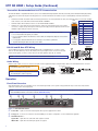
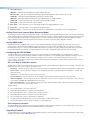
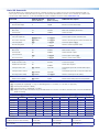
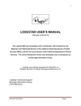
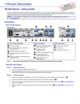
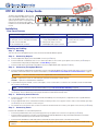
XTP SR HDMI • Setup Guide
The Extron XTP SR HDMI is an XTP receiver
that scales HDMI, DVI, RGB, HD component
video, and standard definition video to the
optimal output resolution. This guide provides
instructions for an experienced installer to
install and connect the XTP SR HDMI scaling
receiver.
SIG
POWER
12V
1.0 A MAX
LINK
OVER XTP
RS-232
a
AUDIO
ON
IR
OFF
XTP IN
LAN
b
c
Tx Rx
G
Tx Rx
d
OUTPUTS
AUDIO
L
+
HDMI
e
−
+
RELAYS
1
R
−
2
S/PDIF
REMOTE
RS-232
RESET
Tx Rx G
f g h ij
Installation
Rear Panel Features
Power and Throughput Connections
Output Connections
Control Connections and Reset
a
b
c
d
e
HDMI output connector and
corresponding HDMI audio switch
f
g
Analog audio output connector
h
i
j
DC power connector and power LED
XTP input connector and Sig and Link LEDs
LAN connector and LEDs
RS-232/IR Over XTP connector
S/PDIF digital audio output connector
Relay connectors
Remote RS-232 connector
Reset button
Mounting and Cabling
Step 1 — Mounting
Turn off or disconnect all equipment power sources and mount the XTP SR HDMI as required.
Step 2 — Connecting Outputs
a.
Connect a digital video display to the female HDMI connector (see e above).
b. Connect a balanced or unbalanced, stereo or mono audio output device to the 3.5 mm, 5-pole captive screw connector (see f above) for
2-channel stereo analog audio (for wiring details, see Audio Wiring on page 2).
c.
Connect an audio device to the female orange RCA connector for digital S/PDIF audio output (see g above).
Step 3 — Connecting Throughput Devices
a.
Connect a twisted pair cable between the XTP input connector of the XTP SR HDMI (see b above) and the XTP output connector on an XTP
transmitter or XTP matrix switcher. For cable recommendations, see Twisted Pair Recommendations for XTP Communication on page 2.
ATTENTION:
Do not connect this connector to a computer data or telecommunications network.
Sig LED — Lights when it receives an active XTP input signal from the transmitter or matrix switcher.
Link LED — Lights when a valid XTP link is established.
b. To pass bidirectional serial, infrared, or other control signals, connect a control device or a device to be controlled to the RS-232 and IR Over
XTP connector (see d above).
NOTE:
RS-232 and IR data can be transmitted simultaneously (see RS-232 and IR Over XTP Wiring on page 2).
d. Connect a host device or control LAN or WAN to the LAN RJ-45 connector for pass-through 10/100Base-T Ethernet communication
(see c above). This is an Ethernet pass-through port with LEDs to indicate link and activity status.
Step 4 — Connecting Control Devices
a.
Connect a host device, such as a computer, to the female mini-USB B port on the front panel to configure the receiver or update firmware
(see b on page 2).
b. Connect equipment that can be controlled via momentary or latching contact, such as projector screens or lifts, to these normally open relays
(see h above). Do not exceed 24 V at 1 A for each port.
c.
For serial RS-232 control of the receiver, connect a host device to the Remote RS-232 3.5 mm, 3-pole captive screw connector (see i above).
Step 5 — Connecting Power
Power the XTP SR HDMI in one of the following methods:
•
Connect the provided external 12 V, 1.0 A power supply to the 2-pole captive screw connector for local power (see a above).
•
Connect an XTP Power Injector to the XTP connection between the XTP SR HDMI and a locally powered XTP transmitter or XTP matrix
switcher (see the XTP Power Injector User Guide for more details).
•
Connect the XTP SR HDMI to an XTP matrix switcher and enable the remote power feature on the XTP matrix switcher.
ATTENTION:
outdoors.
XTP remote power is intended for indoor use only. No part of the network that uses XTP remote power should be routed
1
XTP SR HDMI • Setup Guide (Continued)
Twisted Pair Recommendations for XTP Communication
The XTP SR HDMI is compatible with CAT 5e, 6, 6a, and 7 shielded twisted pair (F/UTP, SF/UTP, and S/FTP) and unshielded twisted pair (U/UTP)
cable. Extron recommends using the following practices to achieve full transmission distances up to 330 feet (100 m) and reduce transmission
errors.
•
Use Extron XTP DTP 24 SF/UTP cable for the best performance. If not using XTP DTP 24 cable, at a minimum, Extron recommends 23 AWG,
Pins:
solid conductor, STP cable with a minimum bandwidth of 400 MHz.
TIA/EIA-T568B
12345678
T568A
T568B
Terminate cables with shielded connectors to the TIA/EIA-T568B standard.
PinPinWireWire
Color
color
Wire co
Limit the use of more than two pass-through points, which may include patch points, punch down
White-green
White-orang
1 1 White-orange
connectors, couplers, and power injectors. If these pass-through points are required, use CAT 6 or 6a
2 Green
Orange
2
Orange
shielded couplers and punch down connectors.
NOTE:
•
•
Loosely place cables and limit the use of tie wraps or hook and loop fasteners.
Insert Twisted
Pair Wires
Separate twisted pair cables from AC power cables.
RJ-45
Connector
White-brown
6 7 Green
7
8
8 Brown
White-brown
Brown
IR Device
RS-232 and IR Over XTP Wiring
To pass bidirectional serial command signals between XTP-compatible devices, connect a control
device to the three leftmost poles (Tx, Rx, and G) of the 5-pole captive screw connector. To transmit
and receive IR signals, connect a control device to the three rightmost poles (G, Tx, and Rx).
NOTE:
White-green
Blue
White-green
4 5 Blue
White-blue
Orange
5 6 White-blue
Do not exceed 40% fill capacity in conduits.
Do not comb the cable for the first 20 m, where cables are straightened, aligned, and secured in
tight bundles.
3 White-orange
4 Blue
RS-232 and IR data can be transmitted or received simultaneously.
Rx Tx G
Tx/Rx
Pins
Tx Rx G Tx Rx
•
•
3
When using CAT 5e or CAT 6 cable in bundles or conduits, consider the following:
IR
•
RS-232
•
Tx Rx G
RS-232 Device
Audio Wiring
Wire the audio output connector as shown to the right. Use the supplied tie-wrap to strap the audio cable to the extended tail of the connector.
L
Tip
Sleeves
Tip
R
R
NOTE:
The length of exposed wires is critical.
The ideal length is 3/16 inch (5 mm).
No Ground Here
Tip
Ring
Sleeves
Tip
Ring
L
ATTENTION:
For unbalanced outputs, do
not connect wires to the “-” poles.
Do not tin the wires!
No Ground Here
Balanced Audio Output
Unbalanced Audio Output
Operation
Front Panel Overview
After all transmitters and connected devices are connected and powered on, the system is fully operational. If any issues arise, verify that the
cables are routed and connected properly.
NOTE:
Use the Extron XTP System Configuration software or SIS commands to configure the XTP SR HDMI (for more details, see the
XTP SR HDMI User Guide on the Extron website, www.extron.com).
a
b
c
d
XTP
CONFIG
e
f
AUDIO
g
ADJUST
ADJ
UST
SIGNAL
HBR
BITSTREAM
LPCM
HDCP
HDMI
S/PDIF
ANALOG
MENU
ENTER
XTP
X
TP SR HDMI
Front Panel
Figure 1. Front Panel Features
a
b
c
Power LED — Lights on the front and rear panels when power is applied to the device.
Config port — Connect a host device to the mini USB B port for device configuration, control, and firmware upgrades.
XTP LED indicators —
Signal LED — Lights when an active XTP video signal is received.
HDCP LED — Lights when the XTP input signal is encrypted.
2
White-blue
Green
White-brow
Brown
d
Audio LED indicators —
HBR LED — Lights when the embedded audio signal is high bit rate audio.
Bitstream LED — Lights when the embedded audio input signal is Dolby Digital, DTS audio format, and 2-ch Dolby.
LPCM LED — Lights when the embedded audio input signal is 2-channel LPCM.
HDMI LED — Lights when HDMI embedded audio output (HBR, bitstream, or LPCM) is enabled.
S/PDIF LED — Lights when S/PDIF audio output (multi-channel or LPCM) is enabled.
Analog LED — Lights when analog audio output is enabled.
e
f
g
Menu button — Press this button to access and navigate the On-screen Display (OSD) menu system.
Enter button — Press this button to select submenus and submenu items.
Adjustment knobs — Rotate the horizontal and vertical knobs to navigate the On-screen Display menu and to adjust settings.
Setting Front Panel Lockout Mode (Executive Mode)
The front panel security lock (executive mode) limits operation of the device from the front panel. While in executive mode, the XTP SR HDMI can
still be configured with SIS commands and the XTP System Configuration Software. To enable or disable executive mode through the front panel,
press and hold the Menu and Enter buttons simultaneously for 2 seconds or until the power LED blinks (see the XTP SR HDMI User Guide to
enable or disable executive mode with Simple Instruction Set (SIS) commands or the XTP System Configuration Software).
Setting HDMI Audio
The embedded audio on the HDMI output connector can be enabled or disabled by setting the HDMI audio switch next to the connector
(see e on page 1). Move and hold the HDMI audio switch up (for about 1 second) to enable embedded audio on the display connected to
the HDMI output connector or move and hold the HDMI audio switch down (for about 1 second) to disable it. The switch returns to the middle
position after it has been released. The associated LED lights when the audio is enabled and remains unlit when audio is disabled.
Configuring the XTP SR HDMI
The XTP SR HDMI can be configured through front panel controls and the On-screen Display (OSD) menu, Simple Instruction Set (SIS)
commands, or the XTP System Configuration Software. To utilize SIS commands or access the XTP System Configuration Software, connect a
host device to the XTP SR HDMI through the front panel Config port (see b on page 2) or the rear panel Remote RS-232 connector
(see i on page 1). The Config port supports SIS commands and the XTP System Configuration Software while the Remote RS-232 connector
supports only SIS commands.
On-screen Display (OSD) Menu System
The OSD menu consists of six submenus that can be accessed using the front panel Menu button. View the menu on a display connected to the
HDMI output connector (see e on page 1). The submenus are:
•
Auto-Image — Use this submenu to perform a one-time Auto-Image on the image. The image is centered and sized to fill the output screen.
•
Picture Control — Use this submenu to adjust the horizontal and vertical position, horizontal and vertical size, brightness, contrast, and
detail of the image.
•
User Presets — Use this submenu to save or recall a user preset.
•
Input Configuration — Use this submenu to view the total pixels and horizontal and vertical active pixels of the input signal.
•
Output Configuration — Use this submenu to select an output rate from a list of common resolutions and refresh rates or view color space,
color bit depth, and HDMI data settings (all three are set to Auto).
•
Advanced Configuration — Use this submenu to apply a test pattern, enable or disable a blank screen, freeze the output, set the aspect
ratio, or reset the receiver to factory default settings.
To adjust settings:
1. Press the Menu button to access the main menu.
2. Rotate either adjustment knob to navigate to a desired submenu.
3. Press the Enter button to access submenu items of a selected submenu.
4. Rotate either adjustment knob to navigate to a desired submenu item.
5. Press the Enter button to select a submenu item for adjustment.
6. As required, rotate the adjustment knobs or press the Enter button to adjust submenu items.
7. Press the Menu button to return to the list of submenus or exit the OSD menu.
XTP Configuration Software
The XTP SR HDMI can be configured by the XTP System Configuration Software when it is installed on a connected host device, such as a PC,
through the front panel USB port (see the XTP SR HDMI User Guide for more details).
Upgrading Firmware
The onboard firmware of the XTP SR HDMI can be upgraded via the XTP System Configuration Software or the Extron Firmware Loader Program
(available on the Extron website, www.extron.com).
3
Basic SIS Commands
The XTP SR HDMI can be configured with specific SIS commands via an RS-232 or USB connection. Use the Extron DataViewer utility or a
control system to send SIS commands and receive responses. The following table identifies a selection of SIS commands (for a full list of SIS
commands and variable definitions, see the XTP SR HDMI User Guide, available on the Extron website, www.extron.com).
Command
ASCII Command
Response
Additional Description
A
Img ]
Execute a one time Auto-Image.
Mute video
1B
Vmt1]
Mute video and display black video.
Unmute video
0B
Vmt0]
Unmute the video.
Set scaler output rate
EX3! RATE}
Rate X3!]
Set the output resolution and refresh rate.
View scaler output rate
E RATE}
Rate X3!]
View the selected output resolution and refresh rate.
Set a test pattern
X1! J
Tst X1!]
Set the test pattern to X1!.
View the test pattern
J
Tst X1!]
View the current test pattern status.
Mute audio
3Z
Amt3]
Mute all audio outputs.
Unmute audio
0Z
Amt0]
Unmute all audio outputs.
Set volume level
X1& V
Vol X1&]
Set the output volume to X1&.
View volume level
V
Vol X1&]
View the current volume setting.
(Host to Device)
(Device to Host)
Input configuration
Execute Auto-Image
Picture adjustments
Output configuration
Audio configuration
Advanced configuration
Enable executive mode
1X
Exe1]
Lock the front panel.
Disable executive mode
0X
Exe0]
Unlock the front panel.
Set aspect ratio to Fill
E 1ASPR}
Aspr1 ]
Set the input aspect ratio to fill the entire output
screen.
Set aspect ratio to Follow
E 2ASPR}
Aspr2 ]
Set the input aspect ratio to match the native value.
View aspect ratio setting
E ASPR}
Aspr X2#]
View the current aspect ratio setting.
E ZXXX}
Zpx]
Resets all user settings back to factory defaults.
Reset
Reset to factory default
NOTES:
X1! = Test pattern (0 = off [default], 1 = crop, 2 = alternating pixels, 3 = crosshatch, 4 = color bars, 5 = grayscale)
X1& = Volume (0-64, where 64 = default)
X2# = Input aspect ratio (1 = Fill [default], 2 = Follow)
X3! = Output scaler resolution and refresh rate (see the table below for a selection of resolutions and refresh rates or the XTP SR HDMI User
Guide for a full list)
SIS Variable
Resolution
X3! for EDID or Output Resolution and Refresh Rate Combination (Where X3! = 10 through 90)
60 Hz
70 Hz
1024x768
23.98 Hz
24 Hz
19
20
21
1280x800
31
32
33
1280x1024
34
35
36
1680x1050
57
58
1920x1200
61
62
720p
1080p
75
76
25 Hz
29.97 Hz
30 Hz
50 Hz
59.94 Hz
66
67
68
69
70
71*
77
78
79
80
81
82
* = default
4
Extron Headquarters
+1.800.633.9876 (Inside USA/Canada Only)
Extron Asia
+65.6383.4400
Extron China
+86.21.3760.1568
Extron Korea
+82.2.3444.1571
Extron Europe
+31.33.453.4040
Extron Japan
+81.3.3511.7655
Extron Middle East
+971.4.299.1800
Extron India
+91.80.3055.3777
© 2013 Extron Electronics — All rights reserved. All trademarks mentioned are the property of their respective owners. www.extron.com 68-2007-50 Rev. A
08 13