1
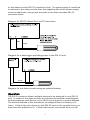
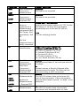
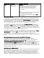
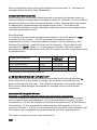
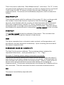
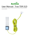
User Manual SDI-12 Soil Moisture
Digital TDT® Sensor with SDI-12 Interface
Part Number: ACC-SEN-SDI
Acclima, Inc.
1763 W. Marcon Ln., Ste. 175
Meridian, Idaho USA 83642
www.acclima.com
2
Table of Contents
Introduction
4
Firmware and Manual Disclaimer
Product Introduction
4
4
Installation and Connection
4
Operation
5
Command Summary
Command Reference
Setting the Address
6
6
8
Making Measurements with the SDI-12 Sensor
8
Non-Concurrent Measurement
Concurrent Measurement
Examples of Using the Sensor
Troubleshooting
8
9
9
12
Specifications
12
Notes:
14
3
Introduction
NOTE: The Acclima Series SDI-12 Soil Moisture Sensor uses the industry
standard SDI-12 interface for communicating with a Data Recorder or other
SDI-12 equipped controller device. The SDI-12 communications standard is
digital serial data communications hardware and protocol standard based
on 1200 baud, ASCII character communications over the three-wire BUS.
The SDI-12 Series is compliant with Version 1.3 of the SDI-12 standard.
Version 1.3 is the latest standard at the time of this printing March, 2015.
Firmware and Manual Disclaimer
This manual was prepared for the current sensor firmware release at the
time of the manual publication. The manual has been thoroughly edited and
is believed to be reliable. Acclima assumes no liability for inaccuracies.
Errata may be published on our website or when deemed necessary by
Acclima. Acclima reserves the right to change any specification(s) without
notice.
You can learn more about Acclima’s products at www.acclima.com or email
questions to [email protected].
Product Introduction
The Series SDI-12 moisture sensor is a Digital Time Domain
Transmissometer that measures the permittivity of soils by determining the
propagation time of an electromagnetic wave transmitted along a waveguide
through the soil. The absolute moisture content of the soil is calculated from
the permittivity using the Topp equation. The sensor can be commanded to
produce both the bulk permittivity and the moisture content of the soil.
The accuracy and stability of the SDI-12 moisture sensor is obtained through
a patented hardware and firmware system that digitizes the return waveform
and them uses proprietary digital signal analysis algorithms to extract the
real propagation time and distortion parameters of the returned wave. High
accuracy is achieved over a wide range of soil temperatures and electrical
conductivity. In the SDI-12 series the resolution of the digitized waveform is
5 picoseconds – permitting a small transducer to report very high resolution
data. From the extracted distortion parameters the transducer calculates
and reports the electrical conductivity of the soil. The permittivity and soil
moisture measurements are compensated for temperature. The transducer
also reports soil temperature.
Installation and Connection
The three wires from the sensor are the SDI-12 connections to the data
recorder. The white wire is the common return or ground terminal on the
data recorder SDI-12 connector block. The red wire is the power line and
must attach to the power supply line on the data recorder SDI-12 connector
block or to the positive side of an external power source. The blue wire is
the bidirectional (half-duplex) data line that attaches to the serial data line
4
on the data recorder SDI-12 connector block. If a power supply is used that
is external to the data recorder then the negative side of the power supply
must be attached to the ground terminal on the data recorder SDI-12
connector block.
Diagram for RS232 (Serial Port) to PC Connection
RED
BLUE
WHITE
Diagram for a data logger providing power to the SDI-12 port
+
-
WHITE
RED
BLUE
Diagram for the data recorder using an external battery
Operation
The SDI-12 protocol allows multiple devices to be attached to one SDI-12
port. In order for the data recorder and devices to facilitate unambiguous
communications each device on the SDI-12 port is given a unique address.
The default address of the transducer (as shipped from the factory) is 0
(zero). If this is the only device on the SDI-12 port on the recorder then you
may leave the address as 0. If other devices are connected then you will
5
need to insure that they each have unique addresses. Setting the address
will be discussed later.
SDI-12 commands are a concatenation of three fields. The first is the device
address. This is a single character – typically in the range of “0” to “9” but
can also use the characters “a” to “z” and “A” to “Z”. The second is the
command which may consist of several characters. The command
characters are always upper case. The last is the command terminator
which is always an exclamation point “!”.
Command Summary
The SDI-12 sensor implements commands that comply with versions 1.0,
1.1, 1.2, and 1.3 of the SDI-12 specifications. All commands require for full
compliance of the version 1.3 specifications are implemented in the SDI-12
sensor. However, the ‘additional measurements’ commands in the SDI-12
specification are meaningless to the Acclima SDI-12 sensors, since the
permittivity, moisture, conductivity, and temperature measurements are all
required and all made with every single measurement. Hence the response
for all of these additional measurements commands is “a<CR><LF>” as
required by the SDI-12 specification. The sensor ignores unimplemented
commands outside those require by the SDI-12 specification. There is no
response to them.
Additional ‘Extended Commands’ that are not innumerate here, are
incorporated by Acclima for digitized waveform dumps and factory
calibration settings and readings.
Command Reference
The table below documents all commands supported by the SDI-12 sensor in
alphabetical order:
Command
?!
Function
Address Query
a!
Acknowledge
Active
Change Address
Start Concurrent
Measurement
aAb!
aC!
aCC!
Sensor Response
a Note: only one device can be connected
to the SDI-12 port when this command is
used.
a
b
a00104
Measurement takes 1 second. 4 values
are returned
Start Concurrent
MeasurementRequest CRC
6
Command
aC1!
.
aC9!
aCC1!
.
acc9!
aD0!
al!
aM!
aMC!
aM!
.
aM9!
aMC1!
.
aMC9!
aR0!
.
aR9!
Function
Start Additional
Concurrent
Measurement
Start Additional
Concurrent
Measurement –
Request CRC
Get First 4 Data
Items in
response to a
Measurement
command: VWC,
Soil Temp., Soil
Permittivity, Soil
EC
Get the
response from a
Verify command
Send
Identification
Start NonConcurrent
Measurement
Start NonConcurrent
Measurement –
Request CRC
Additional
Measurements
Additional
Measurements
– Request CRC
Continuous
Measurement
Sensor Response
a00000
No data to be provided
a00000
No data to be provided
Asppp.ppsTT.skk.kksee.e
ppp.pp is the water content (%) TT.TT is the
soil temp (C) kk.kk is the soil relative
permittivity ee.e is the soil EC (dS/m)
n+a
n is the verifying results
aSSVVVVVVPPPPPPcccxx...xx
a13Acclima0030316.2xx...xx
ss= SDI-12 version 1.3 (2 ch)
v= Vendor ID Acclima (8 ch)
p= Product ID (6 ch)
c= Product Version (3 ch)
xx...xx= Serial Number (13 ch)
a0014
Measurement takes 1 second and returns
4 values.
a
Sensor returns a Service Request after
measurement is made. The data can be
retrieved using a aD0! command
a0000
The SDI-12 sensor does not require the
use of this command. If the command is
received the sensor reports “no data” to be
returned.
a
The SDI-12 sensor does not use this
command and responds with no data.
7
Command
aV!
Function
Start
Verification
Sensor Response
a0031
One data item will be returned after 3
seconds The data item will be the
verification code requested by this
command.
a
The sensor returns a service request after
the measurement is made.
The data can be retrieved using a aD0!
Command.
Setting the Address
If more than one device is wired to the SDI-12 port you will need to assure
that they all are set up with unique addresses. If you are not sure you can
connect them one at a time and use the “Address Query” command “?” to
read the addresses. Only one device can be connected to the SDI-12 port
when using this command. The device will respond with its address.
To change the address of a device use the “Change Address” command.
The syntax is “aAn!”, where “a” is the present address “A” is the Set Sensor
Address command and “n” is the new address. The device will return the
new address. For example, if 0A4! Is transmitted, the sensor address will be
re-programmed to 4 and the sensor will return “4”.
To verify that the SDI-12 sensor is responding to its address use the “Send
Identification” command “al!”. The SDI-12 sensor will respond with
“a13Acclima...” In the response the “a” is the device address, “13”
represents Version 1.3 the SDI-12 standard and the “Acclima” is the vendor
ID.
Making Measurements with the SDI-12 Sensor
There are two commands that cause the SDI-12 sensor to take
measurements and store them for subsequent retrieval. The first is the
“Non-Concurrent Measurement Command” “M”. The second is the
“Concurrent Measurement Command” “C”. The sensor responds to both of
the commands with “atttn” where “a” is the sensor address, “ttt” is the
number of seconds before the data will be ready, and “n” is the number of
data items that will have been prepared. For the Acclima SDI-12 sensor the
number of data items is 9.
Non-Concurrent Measurement
When using the non-concurrent command, the recorder waits for the sensor
to complete its measurement and then retrieves the result. The sensor
sends a “Service Report” code to the recorder after preparing the data so
that the recorder will retrieve the data at the appearance of the Service
Request or after the indicated time has expired, whichever occurs first. The
8
Service Request code is simply the address of the sensor “a”, followed by
carriage return and line feed characters.
Concurrent Measurement
When using the concurrent measurement command the sensor does not
return a service request when the data is ready for retrieval. The recorder is
allowed to perform other communications to other devices while the sensor
is making the measurement and preparing the data. Then when the
recorder is available and the indicated measurement time has elapsed the
recorder retrieves the data.
Data Retrieval
To retrieve the requested measurement data the recorder sends a “D0”
command to the sensor. The D0 command returns the basic 4
measurement items: Volumetric Water Content, Soil Temperature, Soil
Relative Permittivity, and Soil Electrical Conductivity. The syntax for the
command is: “aD0”, where “a” is the sensor address. Below is a table
showing the data available from the SDI-12 sensor and the commands used
to retrieve them.
Data Item Request
Command
Volumetric Water Content aD0!
Soil Temperature
aD0!
Bulk Relative Permittivity
aD0!
Soil Electric Conductivity
aD0!
The format of the returned data is:
Response
Example
+25.03
+/-32.16
+32.13
+1.6
Units
%
C
-dS/m
a+25.03+32.16+32.13+1.6<CR><LF>
Note that the returned data is always preceded by the device address a.
Each data value is preceded by a sign. No units are returned but are
assumed known by the user. The units are as shown in the table above.
Each return data string is terminated by carriage return and line feed
characters.
Examples of Using the Sensor
Example 1: Reading sensors using non-concurrent commands:
This first example shows how a data recorder would obtain 4 data items
from a sensor that has address 5: (1) Volumetric Water Content, (2) Soil
Temperature, (3) Soil Permittivity or Dielectric Constant and (4) Soil Electric
Conductivity. In this example the data recorder will operate in the nonconcurrent mode – that is, it will not spend any time with other sensors until
this sensor has completed its measurements and has reported them.
The first command from the data recorder is:
5M!
9
This command is called the “Start Measurement” command. The “5” in this
command is the address of the sensor you wish to respond to the command.
It will cause the SDI-12 sensor to begin the process of taking a set of
measurements. The sensor will immediately respond to this command as
follows:
50014<CR><LF>
This response starts with the address of the sensor (5), then continues with
the number of seconds that are required to take the readings, 001 (1
second), then finished with the number of data items that will be returned
with each measurement request (4). Every response from the sensor is
terminated with a carriage return and line feed characters. After the sensor
has finished its measurements it transmits a service request to the recorder.
5<CR><LF>
The service request is just the address of the sensor. The recorder then
sends a command to get the first set of data items:
5D0!
The items requested are: volumetric water content, soil temperature, soil
permittivity, and soil electrical conductivity. Upon receiving this command
the sensor responds with:
5+25.03+32.16+32.13+1.6<CR><LF>
The first 5 is the sensor address. The remaining string contains the
requested data items – each preceded by a “+” or “-“ sign.
Example 2: Reading sensor using concurrent commands:
This second example shows how a data recorder would obtain the same 4
data items from a sensor using concurrent commands. In this example the
data recorder will operate in the concurrent mode – that is, it will be free to
service other sensors while the sensor with address 5 is making its
measurements. Concurrent measurement commands use C instead of M in
the command. Thus the command to start concurrent measurement is:
5C!
The sensor immediately responds with:
500104
10
With concurrent commands the sensor does not provide a service request
after the measurements have been made. The recorder relies on the timing
information provided by the sensor and will not request data until the time
interval has expired – in this case 1 second.
The recorder then requests the four data items exactly in the same manner
as with non-concurrent readings.
Data Communication Error Checking
So far, all Start Measurement commands that we have discussed have
requested data wherein no error checking is done to verify the correct
reception of the data by the recorder. The SDI-12 specification provides for
error checking by using an additional command character “C” with the Start
Measurement command. Thus when the commands
aMC! Or aCC!
are transmitted to the sensor, the sensor appends a CRC code to the end of
the returned data. This code is generated from the data in such a manner
that if the data changes in the transmission the change can be detected in
the recorder. If the recorder experiences such corruption in the data it will
repeat the data request automatically.
3.3.6 Verify Command
The SDI-12 specification requires a special command for the purpose of
verifying that the sensor is working properly. Acclima’s implementation of
that command is as follows:
1. The recorder sends out the verify command:
aV!
2. Upon receiving the verify command the sensor will respond with:
atttn
where “a” is the sensor address, “ttt” is the time required to make
verification readings, and “n” is the number of data items that will be
returned. For this command ttt = 003 and n=1.
3. The sensor takes 3 full sets of readings. The corrected propagation times
from the three readings are saved and compared. If any of these
propagation times are out range or if they differ by an unacceptable amount
an error is acknowledged. The sensor then sends out a service request.
a
4. The recorder issue a read data command D0:
11
aD0!
The sensor responds with verification code:
Verification Codes
Value Codes
0
Sensor is good
1
VCC or internal voltage test
2
Test temperature sensor to see if too low
3
Test temperature sensor to see if too high
4
TPD Error
5
Span Error
6
Amp Error
7
Variance Test
Troubleshooting
Problem
No Data Return
by the SDI-12
sensor
Unreadable data
Sensor not
communicating
Unreadable
data/parity errors
Possible Resolution
Check the sensor connections to the data recorder.
The white wire connects to the SDI-12 port Ground
terminal. The blue wire connects to the SDI-12 port
Data terminal The red wire connects to the SDI-12
port V+ terminal or to the positive terminal of an
external battery. If an external battery is used the
negative terminal of the battery connects to the
ground terminal of the SDI-12 port.
Insure that there are no address conflicts.
Disconnect all other devices connected to the
recorder. Insure that the sensor address is used in
the commands you are using.
Check connections
Check Voltage
Check address
Review syntax
Insure that there are no address conflicts.
Disconnect all other devices and try to read again.
Insure that the cable length to the sensor does not
exceed 200 feet.
Specifications
Physical Characteristics:
Dimensions (without cable)
Weight (with 3 meter cable)
Composition
Cable
Environmental Characteristics:
20 cm x 5.33 cm x 1.5 cm
220g
Type 304 stainless steel, crystalline-epoxy,
polyethylene (insulation)
3 conductor, 18 Ga PE sheath, 3 meter
12
Operating Temp Range
Storage Temp Range
Lightning & Surge Protection
Operating Characteristics:
Volumetric Water Content
Resolution
Absolute VWC Accuracy
VWC Temp Stability
VWC Soil EC Stability
Temp Reporting Accuracy
EC Reporting Accuracy
Architectural Characteristics:
Technology
Effective Acquisition Bandwidth
Propagation Time Resolution
Waveform Propagation
Resolution
Waveguide Length
Permittivity to VWC Calculation
Propagation Waveform
Bandwidth
Communications Characteristics:
Communication Protocol
Maximum Cable Length
Maximum Devices per Cable
Power Characteristics:
Operating Voltage Range
Listening/Sleep Mode Current
Communications Current
Read Moisture Comm Time
Moisture Sense Current
Moisture Sense Time
1 C to 50 C
-20 C to 75 C
6kV @ 3kA, 8/50us
0 to 100%
0.06% VWC
+/- 2% typical
+/- 1% of full scale 1 C - 50 C
+/- 1% of full scale 0 to 5 dS/m BEC
+/-2 C 0 to 50 C
+/- 0.2 dS/m 0 to 50 dS/m BEC
Waveform Digitizing Time Domain
Transmissometer
200 Giga-sample/sec.
5 ps
1.5 mm in air, 0.16 mm in water
30 cm
Modified Dielectric Mixing Model
>2 GHz
SDI-12 Revision 1.3
60 meters
50
4 – 15 VDC
12 uA typical, 15 uA max
2.5 mA typical, 4 mA max
425 ms total for each read cycle
30 mA at 12 VDC input
55 mA at 6 VDC input
75 mA at 4 VDC input
450 ms each sensing operation
13
Notes:
14
15
Acclima, Inc.
1763 W. Marcon Ln., Ste. 175
Meridian, Idaho USA 83642
www.acclima.com
toll free 866-887-1470
fax 208-887-6368
User Manual SDI-12 Moisture Sensor 6/10/09 Rev 2
16