1
OWNER'S
MANUAL
MODEL NO.
917.254611
(RRFTXMRN®
Caution:
Read and follow
all Safety Rules
and Instructions
Before Operating
This Equipment
12 HP
LECTRIC STA T
38" MOWER DECK
5 SPEED TRANSAXLE
LAWN TRACTOR
Assembly
Operation
Maintenance
Service and Adjustment
Repair Parts
LUW_U,lUl
.....
............
.....
..........
Sears, Roebuck and Co., Chicago, IL 60684 _J.S.A.
_,_
.............................
_,_
........
.....................
llll
,i
,,,
, ....
,,_,,,,,,,,,,
...=
lip
,
Jiii,ii,,
LOOK FOR THIS SYMBOL TO POINT
OUT IMPORTANT
SAFETY PRECAUTIONS. IT MEANS - ATTENTION!
BECOME ALERT! YOUR SAFETY IS INVOLVED.
I
CAUTION: LOOK FOR THIS WORD TO POINT OUT
IMPORTANT EQUIPMENT PRECAUTIONS.
NOTE: LOOK FOR THIS WORD TO POINT OUT IMPORTANT INFORMATION ABOUT THE OPERATION
AND PERFORMANCE OF YOUR TRACTOR_
RULES FOR SAFE OPERATION
WARNING: This unit is equipped with an internal combustion engine and shouldnot be used on or near any unimproved forest covered,
brush covered or grass covered land unless the engine's exhaust system is equipped with a spark arrestor meetingapplicable local or area
laws (if any). If a spark arrestor is used, it should be maintained in effective working order by the operator.. (See REPAIR PARTS for part
numoer identification).
In the State of California the above is required by law (Section 4442 of the California Public Resources Code) Other States may have similar
Jaws. Federal laws apply on federal lands_
2
3
4
5
6
7.
8,
9.
10
11
12
Know the controls and how to stop quickly. READ THIS
OWNER'S MANUAL and instructions furnished with attachmonte.
Do not allow children to operate the machine Do not allow
adults to operate it without proper instruction.
Do not carry passengers Do not mow when children and
others are around
Always wear substantial lootwear. Do not wear loose fitting
clothing that could get caught in moving parts.
Keep your eyes and mind on your tractor, mower, and the
area being cut Do not let other interests distract you.
Do not attempt to operate your tractor or mower when not in
the driver's seat
Always get on or off your tractor from the operator's left hand
side,
Clear the work area of objects (wire, rocks,etc ) which might
be picked up and thrown
Disengage all attachment clutches before attempting to start
the engine..
Disengage power to attachments and stop the engine before
leaving 't_e operator's position
Disengage power tomower, stop the engine, and disconnect
spark plug wire(s) from spark plug(s) before cleaning, making
an adjustment, or repair, Be careful to avoid touching hot
muffler or engine components
Disengage power to attachments when transportingor not in
use,
13
14
t5
16
t7
18
t9
20
21
22
23
Take all possible precautions when leaving the vehicle
unattended_ Disengage the power take-off, lower the attachments, shift into neutral, se'_the parking brake, stop the
engine, and remove the key
Do not stop or start suddenly when going uphillor downhitt
Mow up and down the face ot slopes (not greater than 150),
never across the face Refer to page 51,
Reduce speed on slopes and make turns gradually toprevent
tipping or loss of control, Exercise extreme caution when
changing direction on slopes
White going up or down slopes, ptace gear shiftcontrol 1ever
in 1st gear position to negotiate the slope without stopping
Never mow in wet or slipperygrass, when traction is unsure,
or at a speed which could cause a skid.
Stay alert for holes in the terrain and other hidden hazards
Keep away from drop-otis
Do not drive too close to creeks, ditches, and public high.
ways_
Exercise special care when mowing around fixed objects in
order to prevent the blades from striking them. Never deliberately run tractor or mower into or over any foreign objects
Never shift gears until tractor comes to a stop
Never place hands or feet under the mower, in discharge
chute, or near any moving parts while tractor or mower is
running Always keep clear of discharge chute
Use care when pulling loads or using heavy equipment
a
Use only approved drawbar hitch points
b. Limit loads to those you can safely control
c.
d
24,
25.
26.
27
28..
29,.
30.
3 !_
32.
33.
34.
35.
36..
37.
38
Do not turn sharply Use care when backing
Use counterweight or wheel weights when suggested in
owner's manuat.
Watch out for trafficwhen crossing or near roadways
When using any attachments, never direct discharge of
material toward bystanders nor allow anyone near the vehicle while in operation,
Handle gasoline with care - it is highly tlammable.
a
Use approved gasoline containers
b. Never remove the fuel cap of the fuel tank or add
gasoline to a running or hot engine or an enginethat has
not been allowed to coot for several minutes after running Never fill tank indoors Always clean up spilled
gasoline
c
Open doors if the engine is run in the garage - exhaust
fumes are dangerous Do not run tl_e engine indoors.
Keep the vehicle and attachments in good operatingcondition, and keep safety devices in place and working,
Keep all nuts, bolts, and screws tight to be sure the equipment is in safe working condition,
Never store the equipment with gasoline in the tank inside a
building where fumes may reach an open llame or spark,.
Altow the engine to cool before storing in any enclosure,.
To reduce fire hazard, keep the engine free of grass, leaves,
or excessive grease, Do not ctean product while engine is
running
Except for adjustments, DO NOToperate engine if aircleaner
or cover directly over carburetor air intake is removed.
Removal of such part could create a fire hazard.
Do not operate without a muffler, or tamper with exhaust
system Damaged mufflers or spark arrestors couldcreate a
fire hazard_Inspect period)ca!iyand replace if necessary.
The vehicle and attachments should be stopped and inspected for damage after striking a foreign object, and the
damage should be repaired before restarting and operating
the equipment
Do notchange the engine governor settings or overspeedthe
engine; severe damage or injury may result
When using the vehicle with mower, proceed as follows:
a
Mow onty in daylight or in good artificial light.
b. Shut the engine off when unclogging chute_
c
Check the blade mounting bolls for proper tightnessat
frequent intervals.
Do not operate the mower without the entire grass catcher,
on mowers so equipped, or the deflector shield in place.
Disengage power to mower before backing up. Do not mow
in reverse unless abso!utely necessa_ and then only after
careful observation of the entire area behind the mower_
Under normal usage the grass catcher bag material is subject
to deterioration and wear. it should be checked trequentlyfor
bag replacement Replacement bags should be checked Io
ensure compliance with the original manufacturer's recom.mendations or specifications.
IIIII
CLaONGR_ATULATIONS on YOUr purchase of a Sears
wn Tractor. It has been designed, engineered and
manufactured to give you the best possible dependability
and performance. Should you experience any problem
you cannot easily remedy, please contact your nearest
Sears Service DepartrnenL We have competent, welltrained technicians and the proper tools to service or
repair this unit.
E
E
:
II1'
SERIAL
NUMBER
DATE OF PURCHASE
MAINTENANCE AGREEMENT
THE SERIAL NUMBER WILL BE FOUND ON TH E MODEL
PLATE UNDER THE SEAT.
A Sears Maintenance Agreement is available on this
prod[Jct. See the nearest Sears store or service centre
for details°
YOU SHOULD RECORD THESE NUMBERS AND KEEP
FOR FUTURE REFERENCE.
CUSTOMER
i ,11,111
iiii _ j i
RESPONSIBILITIES
i
iiii
_
.
Read and retain this manual. Study and observe the safety rules. Always use care when using your tractor., Always
keep your tractor and mower clean+ Follow a regular schedule in maintaining, caring for, and using your tractor, A well
cared for tractor will run better and last tonger_
ATTACHMENTS
This unit can use many attachments now available at your Sears store. It cannot use attachments that engage the ground
like a plow, harrow, cultivator, or tiller.+ See page 50 for a list of available attachments+
LIMITED ONE YEAR WARRANTY
ON ELECTRIC START RIDING EQUIPMENT
For one year from date of purchase, when this ridingequipment is maintained, lubricated,and tuned up accordingto
the operating and maintenance instructionin the owner's manual, Sears will repair free of charge any defect in
matedal or workmanship in this electric startriding equipment.
This warranty excludes blade(s), blade adapter(s), spark plug(s), air cleaner and belt(s), which are expendable and
become worn during normal use,.
This warranty does not cover:
- Tire replacement or repair caused by punctures from outside objects (such as nails, thorns, stumps, or
glass); and
• repairs necessary because of operator abuse or negligence, includingthe failure to maintain the equipmerit according to instructionscontained in the owner's manual; and
. riding equipment used for commercial or rental purposes,.
FULL 90 DAY WARRANTY ON BATTERY
For 90 days from the date of purchase, if any battery includedwith this riding equipmentproves defective in material
or workmanship and our testing determines the battery will not hold a charge, Sears will replace the battery at no
charge.
WARRANTY SERVICE IS AVAILABLE BY CONTACTING THE NE.AREST SEARS SERVICE CENTER/DEPARTMENT.
This warranty gives you specific legal rights,and you may also have other rights which may vary from state to state_.
SEARS, ROEBUCK AND CO+, D/731CR-W SEARS TOWER, CHICAGO, iL 60684
NOTE: THE ILLUSTRATIONS SHOWN IN THIS MANUAL ARE TO AID tN THE ASSEMBLY AND OPERATION OF
YOUR TRACTOR+ THEY MAY OR MAY NOT SHOW THE ACTUAL MODEL YOU HAVE PURCHASED.+
3
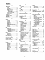
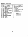
iNDEX
F
Filter:
Options:
Air Cleaner .............................. 16
Attachments ........................... 50
Adjustments:
Brake .........................................14
Fuel ...........................................
18
Spark Arrester ..................
2,32
Carburetor .............................. 18
Fuel:
Mower Drive Belt .................... 22
P
Type ..........................................
10
Mower
Storage ................................................
23
ParkingBrake .....................
9
Front-To-Rear ...............................
23
Fuse ...................................................................
19
Parts Bag .............. :..................... 5-6
Side-T'ooSide..................... 22
Parts,- Replacement/Repair ..... 28-46
H
Throttle Control Cable ............18
Hood Removal/Installation ..................
20
R
Engine Valves ...............................
18
Air Cleaner ................................... 16
Repair and Adjustments ..........
14-24
L
Air Screen, Engine ................................
16
Blade ..........................
14
Carburetor .....................
18
Assembly ..................................... 5_9
Leveling Mower Deck .........................
22
Lubrication:
Attachments .........................................
50
Fuse ..........................
19
Chart ...............................................
24
Hood Remeval/Installation.....20
B
Tractor Pivot Points .........................
17
Motion Drive Belt
Battery:
Removal/Replacement ..... 19
M
Mower Ddve Belt
Charging ..........................................
7, 17
Maintenance ............................................................
13
Cleaning ................................................
15
Removal/Replacement .....22
Installation .............................................
8
Air Cleaner ...............................16
Mower Adjustment
Foam Pre-cleaner ...................
16
Levels ...........................................................
15
Front- to-Rear ................
23
Side-to-Side ........................22
Preparation .............................. 7
Air Screen, Engine ...................
16
Mower Removal .................
21
Starting with Weak Battery .... 17
Battery ...........................................
15
TireCare ......................
14
Storage ..............................................
23
Blade Sharpening .......................
14
Terminals ...................................15
Brake Adjustment .........................
14
Repair Parts .......................
28-46
Belt:
EngineOil....................................
16
Motion Drive
Fuel Filter ................................
18
S
Lubrication
Chart
.......................
24
Removal/Replacement .........
19
Safety Rules .......................
2
Mower Drive
Seat .............................
8
Spark Plug .........................................
18
Tire Care ...........................................
8,14
Service Record .....................
13
Removal/Replacement .......22
Mower:
Adjustment ...................................
22
Slope Guide Sheet ..................
51
Blade:
Adjustment, Front-to-Rear .....23
Spark Plug .......................
18
Sharpening ...................................
14
Adjustment, Side-to-Side ............
22
Speed Control Chart .................
12
Replacement ............................ 14
Blade Sharpening ..............................
!4
Starting the Engine ..................
11
Brake Adjustment ..............................
14
Blade Replacement .....................
14
Steering Wheel .............................................
7
Cutting Level .........................
t 2,22
Stopping the Tractor ..............................
10
C
Installation .............................................
21
Storage ...........................
23
Carburetor Adjustment ........................
t8
Operation ..........................................
11
Removal ....................................
21
T
Controls, Tractor ......................................
9
Throttle Control Cable
Cutting Level, Mower .....................
12,22
Mowing Tips ......................................................
12
Muffler .................................................
17
Adjustment .....................
18
E
Spark Arrester .................... 2,32
Tires .............................
8,14
Engine:
Trouble Shooting Chart .............
25-26
Air Screen ...........................................
16
0
Transaxle:
Oil:
Oil Change ....................................................
15
Repair Parts ...............................
40-41
Oil Level ......................................
16
ColdWeather Conditions
........
16
Warranty ......................
48
Oil Type ......................................
16
Engine....................................
16
Transporting ..........................................
12
Preparation ..........................................
10
Storage ..................................
23
V
Repair Parts ..............................
42-46
Operation ......................................................
9-12
Starting ..............................................
10
Operating Your Mower .......... 11
Valve Adjustments ...................
18
Storage ..................................................
23
Operating Your Tractor ..............
11
W
Starting the Engine ......................
10
Stopping Your Tractor ...................
I0
Warranty ..........................
3
Tractor Operation on Hills .......12
Wiring Schematic ...................
27
A
4
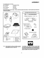
ASSEMBLY
To assemble tractoryou wilt need:
(2) 7116"wrenches
Tire Pressure Gauge
(1) 1!2" wrench
Screwdriver
(2) 9/1 6"wrenches
Utility Knife
(1) 3/4" wrench
5/16" Wrench
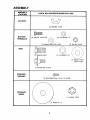
Take all of the Items out of the box. The box contatns the Items shown below. Open the parts bag and check the
contents (see page 6).
Parts bag contents not shown full size
(2) Battery Carriage Boils-
1/4 x 20 x 7 1t2
C
D
Terminal Guard
G
A
(2) Keys
!5 ° Slope Instruction
B
Steering Wheel Adapter
F
a,
Seat
d.
Battery Acid
b,
c,
Steering wheel
Battery
e
f
g,
Owner's Manual
Parts Bag
Steering Boot
NOTE:
Battery Caps and
Instructions
Steering Wheel Insert
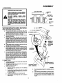
The operation of any tractor can result in foreign objects
thrown into the eyes, which can result in severe eye damage Always wear safety glasses or eye shields before starting your tractor and while moving, We recommend Wide Vision Safety Mask for over the spectacles or standard safety
glasses, available at Sears Retail or Catalog Slores
RIGHT HAND(R,H,) AND LEFT HAND (L.H_) ARE
DETERMINED
FROM OPERATOR'S
POSITION
WHILE SEATED ON THE TRACTOR
5
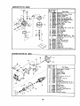
ASSEMBLY
ASSEMBLY
PARTS
LOCATION
BAG CONTENTS
i ll,lll,
SHOWN
ll,ll,/
ii,
FULL SIZE
iii
BATTERY.
(2) Wing Nut 1/4-20
BATTERY
(2) Lock Washer
©
1/4
TERMINALS
(2) Washer
9/32 x 5/8 x 16 Ga
(2) Hex Nut 1/4-20
=
SEAT
d
(1) Adjustment
Bolt
(1) Lock Washer
1/2
t
(1) Washer 17t32x
1-3/16 x 12 Ga
(1) Shoulder Bolt
5/16-18
STEERING
BUSHING
(2) Sheet Metal Screw
ill
10-16 x t/2
=lllllllll
=lllll= =llllllllH
ABTBS
==jlll/i
i=
WHEEL
(1) Locknut 1/2-20
asher
6
2-1/4
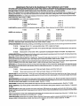
ASSEMBLY
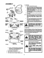
1. Prepare Battery
WEAR EYE AND FACE SHIELD.
CUT AWAY VIEW
WASH HANDS OR CLOTHING IMMEDIATELY IF ACCIDENTALLY
IN CONTACT
WITH BATrERY ACID.
CHARGED
DO
NOT
PLOSIVE
_
BATTERY
SMOKE.
!.........
BATTERY
VENT TUBE
ACID ARE EXFUMES
FROM
lid
LEVEL
READ THE INSTRUCTIONS
INCLUDED
WITH THE BATTERY
VENT CAPS IN
THE BAG OF PARTS. ALWAYS WEAR
GLOVES, CLOTHING
AND GOGGLES
TO PROTECT YOUR HANDS, SKIN AND
EYES.
BATTERY
CELL
FIGURE
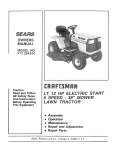
Fill and charge battery (before installing).NOTE: SEE DETAILED INSTRUCTIONS PACKAGED WITH BATTERY
VENT CAPS FOUND IN BAG OF PARTS.
a.
bo
c.
d.
eo
In
Filleach celt with battery acid, Add the acid until it
reachesthe bottomof the venttubes (Fig. I)° Do not
add the acid beyond thislevel or the additional acid
can come out when the battery is charged.,
Alter cells are filled, tilt battery from side to side to
release air bubbles°
Allow battery to stand and settle for at least thirty
minutes. If the level of acid falls below the pointdescribed in step (a), add more acid until the correct
level is reached°InstaUthebatterycaps, foundin the
bag ofparts,to cover the venttubes°Wash the topof
the batterywith water to remove any acid, then wipe
dry.
Check battery case for leakage to make sure that no
damage has occurredin handling.
Neutralize excess battery acid for disposal by addingitto2 gallons(7 litres) ofwater in a five gallon(20
litres) plasticcontainer. Stir with a woodenor plastic
paddle while addingbakingsoda untilthe addition of
more soda causes no more foaming_.
tt is recommended that the battery be charged before use. Llse a 12 volt battery charger_Charge battery at a rate of 6 amperes for 1 hour. NOTE: OBSERVE SAFETY PRECAUTIONS, LISTED tN BOX
ABOVE, REQUIRED FOR BATTERY CHARGING.
Check the acid level after the battery is charged, if
the acid has fallen below the correct level, add distilled or iron free water_
1
I_"NUT
2.1/4"DIA.WASHER_
STEERING
SCREW_
.,_STEERING
WHEEL
ADAPTER
STEERING
BOOT
STEERING
BUSHING
2. Unpack Tractor
ao Cut down four comers of the cartonwith utilityknife
and fold down sides.
bo Disengage parkingbrake and position frontwheels
straight ahead (see page 9),
c Installsteering wheel
STEERING SHAFT
(REC'D. POSITION)
STEERING SHAFT
(INST. POSITION)
FIGU 2
!_ Slide the steering bushing over the steering
shaft (Fig° 2).
2. Positionsteeringshaftforwarduntilscrew holes
in dash lineup with steeringbushing install two
(2) screws (Fig, 2),
3, Positionsteering boot over steering shaft,
4_ Place bottom of steering boot over two slots in
dash (Fig, 2),,
,,
7.
7
Push steeringboot down into aligningsiot;son
dash.
Place steering whee! adapter on steering shaft
With frontwheels pointed straight ahead, place
steering wheel on steering wheel adapter.=Bars
of steering wheel should point straight across
tractor_
ASSEMBLY
3_
SEAT
Install Seat
a_
Remove cardboard from seat pan°
b,,
Place seat on seat pan_Screw adjustment bolt, lock
washer and flat washer into seat (Fig. 3). Screw
shoulder bolt into seat (Fig, 3), Adjustment bolt,
shoulder boll and washers found in bag of parts
(shown fullsize on page 6).
Tighten shoulder bolt using a 1/2" wrench. NOTE:
THE SHOULDER BOLT WILL BE LOOSE IN THE
SEAT PAN SLOT.
SEAT PAN
SHOULDER
BOLT
\
C_
dr,
ADJUSTMENT
BOLT
NOTE: SEAT POSITION SHOULD BE ADJUSTED FORWARD OR BACKWARD SO THAT THE OPERATOR CAN COMFORTABLY REACH CLUTCH/
BRAKE PEDAL AND SAFELY OPERATE TRACTOR°
FLAT
WASHER
LOCK
WASHER
e.. Place seat in operating position° Sit on the seat and
press clutch/brakepedal all the way down. If oparatmg position is not comfortable, adjust seal
fo To adjust: raise seat. Loosen adjustmentboll_Slide
seat to desired position..Tightenadjustment bolt securely.
FIGURE 3
POSITIVE
WASHER
WASHER
NEGATIVE
HEX BOLTS
POSITIVE
CABLE
(RED)
Tighten adjustmentboll, lock washer and flatwasher securely,
. NEGATIVE
CABLE
(BLACK)
...
A
AND FLAT WASHER MUST BE TIGHTADJUSTMENT
ENED
SECUREI.Y
BOLT,
TO PREVENT
LOCK WASHER
MOVEMENT OF SEAT.
4. Check Tires
Check the air pressure in the tires. Tires with too much air
pressure will cause the unit to ride rough_ The wrong air
pressure will also keep the mower from cutting level. The
correct air pressure is shown on the side of the tires,if the air
pressure is not shown, set to pressures shown in the REPAIR AND ADJUSTMENT section (page 14)_
tEX
RGURE 4
TERMINAL
WING NUT
WING NUT
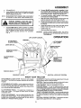
5. Install Battery
BATTERY
BOLT
BEFORE INSTALLING BATTERY, RE-
!
WATCH BANDS, RINGS, ETC. FROM
MOVE PERSON,
METAL BRACELETS,
WRIST
YOUR
TOUCHING THESE
ITEMS TO BATTERY TERMINALS
I
I|
I
BATTERY
DOORS
FIGURE S
BATTERY
DRAIN TUBE
WEAR EYE AND FACE SHIELD,
WASH HANDS OR CLOTHING IMMEDIATELY IF ACCIDENTALLY IN CONTACT
WITH BATTERY ACID.
HOLE
CHARGED BATTERY ACID ARE EXDO
NOT SMOKE. FUMES FROM
PLOSIVE.
8.
Place 2 1/4" diameterwasher on steering shaft
and install a 1/2" iod_nut (washer and locknut
found in bag of parts).Tighten securely.
9. Snap insert into steedng wheel.
d_
Remove plastic on tractor hood.
e_ Raise attachment lift handle (see page 9),.
f
Roll Tractor off skid. Be careful of staples in skid,
READ THE INSTRUCTIONS INCLUDED
WITH THE BATTERY VENT CAPS IN
THE BAG OF PARTS. ALWAYS WEAR
GLOVES, CLOTHING AND GOGGLES
TO PROTECT YOUR HANDS, SKIN AND
EYES.
8
ASSEMBLY
a
b
Lift seat (Fig 3).
Lower battery intofender well withbattery terminals
toward front of tractor (Fig 4). Make sure battery
rests in battery tray (Fig 5)
NOTE: BE SURE BATTERY DRAIN TUBE IS SECURELY
ATTACHED TO BATTERY TRAY DRAIN (Fig 5)
d.. Connect BLACK grobnd cable to negative (-) battery terminal with remaining hex bolt, flat washer,
lockwasher and hex nut (shown full size on pg, 6)
foundin bag of parts, Tighten securely (Fig, 4),,
e, To prevent corrosion, applj grease to lhe batlery
terminals after installing cables_
f. Slide two battery bolts throughterminal guard and
start the wing nuts onto the threads (Fig. 5)
g. Position terminal guard o_;erbattery as shown (Fig.
5) and align bolt heads with key holes next to battery
tray (FigS)
h Lower bolt heads into key holes and slide square
shaftsof bolts into slots of key holes(Fig 5)
i
Tightenwing nuts
J Closeterminal access doors
I
NECTED FIRST TO PREVENT SPARKS
POSITIVE
TERMINALGROUNDING.
MUST BE CONFROM ACCIDENTAL
Connect RED battery cable to positive (+) battery
terminal with hex bolt, flat washer, lock washer and
hex nut (shown fult size on pg 6) found in bag ol
parts Tighten securely with two 7/16" wrenches
(Fig, 4)
CAUTION:
DO NOT START ENGINE UNTIL YOU HAVE
REVIEWED THE OPERATION SECTION OF
THIS MANUAL,
OPERATION
LIFT LEVER PLUNGER
IGNITION\
ATTACHMENT
CLUTCHLEVER_
;HMENT
LIFT LEVER
HEIGHT ADJUST_
VENT SLOTS
LIGHT SWITCH__._!
THROTTLE/CHOKE-_,_
CONTROL
_
T_
\
CLUTCHIBRAKE
PEDAL
"_"'-,.,,_
p..__ ADJUSTMENT
POSITIONING
I
PARKtNG BRA_E
""
DECK
/
/
GEARSHIFTLEVER
NEUTRALLOCK
OUTPOSITION
KNOW YOUR TRACTOR
ATTACHMENT CLUTCH LEVER: Push lever up to engage
attachment There will be an engine hesitation as the clutch
engages
GEARSHIFT: Press the clutch/brake pedal down firmly and
move gearshift lever to desired speed.
IGNITION: Place key in ignitionand turn to the right to start,
The switch spring returns from the start position
LIGHT SWITCH: Turns the headiights on and off.
PARKING BRAKE: To set the parking brake, push the
clutch/brake pedal completely down, Hold the parking brake
lever in "Engage" position and release pressure from pedal.
Clutch/brake peda! will remain in brake position,
THROTTLE/CHOKE CONTROL: Use the throttle control to
increase or decrease the speed of the engine, and to choke
the engine for starting Push lever to the right and forward to
choke.
NEUTRAL LOCKOUT POSITION: Transmission is disengaged when gearshift lever is in this position,
ATTACHMENT LIFT LEVER: Use the attachment lift lever
to r3ise and lower the attachment mountedto your tractor.
Pull lever back slightly and push button, then move the lift
lever forward to lower attachment
CLUTCHIBRAKE
PEDAL:
The pedal has 2 functions: a
clutch and a brake TO engage the brake push the pedal
completely down,
HEIGHT ADJUSTMENT:
Use the height adjustment slots
to adjust the mower height, Push the attachment lift lever
plunger down and position the attachment
lift lever into the
desired slot Release lift lever plunger
9
OPERATION
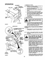
1. Stopping Your Tractor
AIR SCREEN
NOTE: REMOVE KEY WHEN LEAVING TRACTOR TO
PREVENT UNAUTHORIZED USE:
OIL FILLER
CAP/DIPSTICK
FUEL TANK
a
Push clutch-brake pedal intofull "BRAKE" position,,
Keep your foot on pedal (Fig 7).
b,, Place attachment clutch lever in "DISENGAGED"
position_
c. Move gear shift lever tp "NEUTRAL" position,_
d_ Lift up to place parking brake in "ENGAGED" position (Fig. 10) and release pressure from clutch/
brake_ Pedal should remain in "BRAKE" position,,
e Move throttle control to "S" (slow) position.
L Turn ignitionkey to"OFF" position_Never usechoke
to stop engine_
2, Preparing the Engine
FUEL
CAP
FORE ATTEMPTING TO START TH E ENLEARN TO STOP YOUR TRACTOR BEGINE
/
a
OIL DRAIN
FIGURE
6
IGNITION KEY
This engine has been shipped filled with summer
weight oil (For cold weather operation see chart
page 16). Check engine oil level.. Refer to REPAIR
AND ADJUSTMENT section (page 16).
Changing oil after the first two hours (or two mowings) will
help eliminate break-in residue which might be damaging to
your engine..
ATTACHMENT CLUTCH LEVER
"ENGAGED" POSITION
b
Fill fuet tank (Fig..6). Use fresh, clean, regular unleaded gasoline. Capacity is 5 quads (473 litres)..
"DISENGAGED"
POSITION
NOTE: FRESH, CLEAN WINTER GRADE FUEL MUST
BE USED TO INSURE GOOD COLD WEATHER
STARTING
ffi
FILL
PARKING
BRAKE
SWITCH
A
BOTTOM
OF
GAS
TANK
WiPE OFF ANY SPILLED OIL OR FUEL.
FILLER NECK. DO NOT OVERFILL.
DO NOT STORE, SPILL OR USE GASOLINE NEAR AN OPEN FLAME.
I
|
|
!
POSITION
THROTTLE
CONTROL
CAUTION:
GEARSHIFT
LEVER
"CLUTCH"
POSITION
EXPERIENCE INDICATES THAT ALCOHOL
BLENDED FUELS (CALLED GASOHOL OR
USING ETHANOL OR METHANOL) CAN ATTRACT MOISTURE WHICH LEADS TO
SEPARATION AND FORMATION OF ACIDS
DURING STORAGE.. ACIDIC GAS CAN
DAMAGE THE FUEL SYSTEM OF ANY ENGINE WHILE IN STORAGE
TO AVOID ENGINE PROBLEMS, THE FUEL
SYSTEM SHOULD BE EMPTIED BEFORE
STORAGE FOR 30 DAYS OR LONGER.
DRAIN THE GAS TANK, START THE ENGINE AND LET IT RUN UNTIL THE FUEL
LINES AND CARBURETOR ARE EMPTY.
USE FRESH FUEL NEXT SEASON SEE
STORAGE INSTRUCTIONS
FOR ADDITIONAL INFORMATION..
CHOKE
CLUTCH/BRAKE
I
"BRAKE"
POSITION
TO
FAST
"DRIVE" POSITION
SLOW
NEVER USE ENGINE OR CARBURETOR
CLEANER PRODUCTS IN THE FUEL TANK
OR PERMANENT DAMAGE MAY OCCUR
FIGURE 7
10
OPERATION
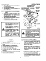
3. Starting the Engine
ao Move throttle control lever (Fig° 7) past "FAST" to
the =CHOKE" position.
bo Fullydepress clutch/Drake pedal,
co Turn ignition key to "START" and release key as
soon as engine starts,
CAUTION:
d
e
L
ATTACHMENT CLUTCH
LEVER =ENGAGED"
POSITION
ATTACHMENT CLUTCH
LIFT LEVER
LEVER "DISENGAGED"
PLUNGER
POSITION
LIFT LEVEP
"HIGHEST"
POSITION
LEVEF
"LOWEST"
POSITION
DO NOT RUN STARTER CONTINUOUSLY
FOR MORE THAN FIFTEEN SECONDS PER
MINUTE.
tf engine does not start after fouror live tries, move
throttle control lever to "FAST" position, wait a few
minutes and try again If the engine does not start
after four or five more tries, see the
TROUBLESHOOTING Chart (page 25)
After the engine starts move throttle control lever
slowlyto the "SLOW" position
To start a hot engine move the throttlecontrollever
to a position between "FAST" and "SLOW"
READ THE "RULES FOR SAFE OPERATION" CAREFULLY BEFORE OPERATING YOUR MOWER,
&
R.H. RUNNER
DO NOT OVER LOAD TRACTOR BY
TOWING WEIGHTS GREATER THAN
150 POUNDS (68 KG).
DISCHARGE
GUARD
ALWAYS WEAR SUBSTANTIAL FOOTWEAR AND AVOID LOOSE FITTING
CLOTHING
THAT
COULD
GET
CAUGHT IN MOVING PARTS.
WHEN PARKING BRAKE IS ENGAGED,
MAKE SURE IT WILL KEEP TRACTOR
DO NOT OPERATE THE MOWER WITHOUT EITHER THE ENTIRE GRASS
CATCHER,
ON
MOWERS
SO
EQUIPPED,
OR THE DEFLECTOR
SHIELD IN PLACE.
NEVER MOVING.
FROM
PLACE YOUR HANDS OR FEET
IN OR UNDER ANY POWERED ATTACHMENT OR NEAR ANY MOVING PART
WHILE TRACTOR OR ANY POWERED
ATTACHMENT IS RUNNING.
4. Operating Your Lawn Tractor and Mower
NOTE: THIS TRACTOR IS EQUIPPED WITH AN OPERATOR PRESENCE SENSING SWITCH. ANY ATTEMPT BY THE OPERATOR TO LEAVE THE
SEAT WITH THE ENGINE RUNNING AND THE
ATTACHMENT CLUTCH LEVER ENGAGED WILL
SHUT OFF THE ENGINE_
CAUTION
TO AVOID
RGURE8
INJURY
1o Read owner's manuaL
2, Know location and functionof all controls,
3. Keep guards, safety shield and switches in place and
working°
4.. Remove objects that can be thrown by blades_
5o Do not mow when children and others are around
6, Never carry children or passengers
7. Always took behindmachine before backing.
8. Do not mow where machine can tip or slip.
9. If machine stops going uphill, stop blades and back
slowlydown,,
10. Be sure blades and engine have stopped before placing
hands or feet near the blades,
11., Remove key when leaving machine_
CAUTION: DO NOT ADD ADDITIONAL WEIGHT
TO THE TRACTOR OTHER THAN THE OPTIONAL
WHEEL
WEIGHTS.
EXCESSIVE
WEIGHT MAY OVERLOAD AND DAMAGE THE
TRANSAXLE,
a.
b,
c.
11
Depress lift lever plunger and move the attachment
lift lever to the highest position, See Fig. 8,
Start the engine,, (See Starting the Engine),
Move the throttle lever to mid range position, Fully
depress clutcWbrake pedal. Select a low (fst or 2nd)
gear until you become more tamiliar with the operation of the unit.
OPERATION
[
i
iN ,H n _
a,
Mower should be adjusted propedy front to back
and side to side for good mowingperformance. Refer to REPAIR AND ADJUSTMENT section(page
22),
b,
Use the runner on the R,H. side as a guide; the
blade cutsapproximatelyan inchoutsidethe runner
...
(Fkj.8)
c
FIGURE
d.. When mowing/arge areas (Fig. 9), start by turning
to the right so that the clippings will discharge away
from shrubs, fences, driveways, etc. After two or
three rounds, mow in the opposite direction making
left hand turns until finished_
9
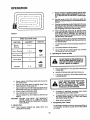
SPEED SELECTION GUIDE
i/1_
Driveso thatclippingsare dischargedontothe area
that has been (_t Have the cut area to the right of
the _chine This willresultin a more even distribution of clippingsand more uniformcutting.
iiii
II
FUNCTION
I IIIII
IlL
iiiii
GEARSHIFT
e_ It grass is extremely tall, it shouldbe mowed twice
The first time cut relatively high; the second time to
tile desired heighL
....
THROTTLE
i,m
Ill
2or 3
Normal
Mowing
Heavy Mowing "
1
Snow Blade
2
4-5
Transport
The left hand side of mower should be used for trimming.
g
See Speed Selection Guide (above).
h_ Do not mow tall, dry (brown) grass over 6 inches
(1524 cm) tall, ft is a fire hazard.
lor2
Snow Blowing
f.
6. Operating the Tractor on Hills
FAST
SLOWFAST
,, ,,,,,
a_ Move gearshift lever to "lst" gear before starting up
or down hills
b.
AVOID STOPPING OR SHIFTING ON HILLS.
c.
If slowing is necessary, move throttle controllever
to slower position.
!
d.
Slowly release clutch/brake pedal and proceed to
the mowing area,
e Stop the unit, then select a mowing speed (See
Speed Selection Guide, page 12).
f, Move throttle lever to half throttle and slowly move
attachment clutch lever to engaged position, Fig 8..
g Slowly release clutch/brake pedal.
h. Move throttle lever to fast position..
i. Observe height of cut and readjust as desired (see
page 9)_
CAUTION: BEFORE YOU MOVE THE GEARSHIFT
LEVER, COME TO A COMPLETE STOP.
FAILURE TO DO SO CAN RESULT IN GEAR
BOX DAMAGE.
.
m
i _
m
I
LE,w
d
If stopping is absolutely necessary, push clutch/
brake pedal quickly to brake position_
e
To restart tractor movement, make sure tractoris in
the lowest speed range ('1st" Gear) and release
clutch/brake pedal SLOWLY°
f
Make all turns gradually.
7. Transporting
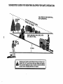
5. Mowing Tips
NOTE: TIRE CHAINS CANNOT BE USED WITH THE
MOWER ATTACHED_
ENOUGH ROOM WHEN STOP-
,...G
,.,.o
s,,..T..G
To...Low
SLIGHT TRACTOR ROLL DOWNHILL
,s
,OVE
,,,DUG.
cLU,C,
POS.T,0.
Your Tractor
Forpushir_ or towing your tractor, place gearshift lever
in "N" posit|on Do not tow or push at more than 6 MPH
(9 7 KPH).
12
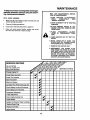
MAINTENANCE
To keep your tractor running
perform necessary
service
ing maintenance
schedule:
WITH
EVERY
better and longer,
using the tollowFOR
ANY AI_JUSTMENTS,
TION OR MAINTENANCE:
1.PUSH
TRACTOR
CLUTCH/BRAKE
PEDAL
COMPLETELY
INTO
"BRAKE"POSITION.
MOWING
t
Make sure all nutson bolts are tightand cotter pinsand
retainer springs are secure
2
Observe all safety precautions
3
Keep tractorwell lubricated (refer to page 24),.
4
Make sure areas around muffler, engine and mower
deck are clean and free of debris buildup,,
INSPEC-
2. MOVE GEARSI'tlFT TO "N" NEUTRAL
POSITION.
=
3. PLACE PARKING
BRAKE IN "EN_
GAGED" POSITION. REMOVE FOOT
FROM PEDAL,
4oPLACE
LEVER
TION.
ATTACHMENT
CLUTCH
IN "DISENGAGED"
POSI-
5. TURN IGNITION
SITION.
KEY TO "OFF"
PO-
6. MAKE
ABSOLUTELY
SURE
THE
BLADES AND ALL MOVING PARTS
HAVE COMPLETELY
STOPPED.
7. REMOVE
THE IGNITION
KEY.
8. DISCONNECT
THE SPARK
PLUG
WIRE FROM THE SPARK PLUG AND
KEEP WIRE AWAY FROM THE PLUG
TO PREVENT INJURY FROM ACCIDENTAL STARTING,
BE CAREFUL
TO AVOID TOUCHING HOT ENGINE
OR MUFFLER COMPONENTS.
I
Change Engine Oil
Check Brake Operation
Check Tire Pressure
V'
Clean Air Screen
v'
Clean Air Cleaner
,,,,,,,,,
v'
Lubricate Pivot Points (see page 24)
Check Battery Level and Recharge
Clean Battery and Terminals
v'
camuretor Adjustment
v'
V-Belt Adjustment ....
v'
Clean Engine Cooling Fins .....
Check Muffler
Replace Air Cleaner Paper Cartridge
......
.y_
v'
Replace Spark Plug
Replace Fuel Filter
Adjust Valves
13
REPAIR AND ADJUSTMENT
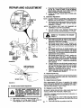
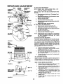
1. Brake Adjustment
This tractor is equipped with an adjustable brake system
mountedon the nghtside of the transaxle (Fig. 10).
II
IWITH PARKING
ENGAGED)
IIII UUlIIIIIIIII
SIX FEET (1.8 METERS) STOPPING
IF TRACTORINREQUIRES
MORE THEN
THAN
DISTANCE
HIGHEST GEAR,
BRAKE MUST BE ADJUSTED.
a
NUT"A"
BRAKE
JAM NUT
BRAKE
ARM
DISC BRAKE
RGUREIO
Depress clutctVbrake pedal and engage parking
brake.
b_ Measure distance between brake operating arm
and nut "A" on brake rod,,
c. tf distance is other than 1-1/2" (3.81 cm), loosen
jam nut (Fig, 10) and turn nut until distance becomes 1-1/2" (3,81 cm)_ Relighten jam nut against
nut "A".
Road test tractor for proper stopping distance as stated
above, Readjust ff necessary,, If stopping distance is still
greater than 6 feet (1.8 meters) in highest gear, further
maintenance is necessary Contact your local Sears Service Center,
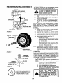
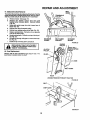
2. Tire Care
a, Maintain tire pressure in front at 14 PSI (lKg/cm 2)
and rear tires at 10 PSI (0,7 Kg/cm2)
b Keep tires free of gasoline, oil, or insect control
chemicals which can harm rubber,.
c
HUB CAP
WASHERS
KLIP RING
SQUARE KEY
(REARTIRE ONLY)
FIGURE
FIGURE
11
12
@
Avoid stumps, stones, deep ruts, sharp objects and
other hazards that may cause tire damage.
d, Removing wheel for tire repair (Fig,,11).
1, Block up axle securely,
2. Remove hub cap, klip ring and washer to allow
wheel removal (rear wheel contains a square
key - Do Not Lose).
3. Repair tire and reassemble. Align slots in rear
wheel hub and axle. Insert square key. Replace washers and snap klip ring securely in
axle groove. Replace hub cap,,
NOTE: USE GREASE FITTINGS TO LUBRICATE FRONT
WHEELS WITH GENERAL PURPOSE GREASE,
APPLY AN ANTI-SEIZE OR GOOD GENERAL
PURPOSE GREASE TO LUBRICATE REAR AXLES,
3. Blade Care
For best results,mower blades must be kept sharp, The
blades can be sharpened with a few strokes of a file,or on a
grinding wheel, We suggest they be sharpened after every
25 hours of mowing, Do not attempt to sharpen while on
mower. If you mow in sandy soil check the blades alter each
two mowings. The sand wears the blades away rapidly,
a, Blade Replacement
Raise mower to highest position to permit access Io
blades,
1, Remove the hex head bolt, iockwasherand flat
washer (Fig 12) (tum counterclockwise).
2, Remove and discard old blade,
3., Clean top and bottom of mower housing
4 Install new blade with SHARP EDGE DOWN
and secure with flat washer, Iockwasher and
hex head boll TIGHTEN SECURELY_
ALWAYS
USEGRADE
S HEAT
A GRADE
5 HEAT TREATED
BOLT CAN BEIDENTIFIED
BY
THREE LINES ON THE BOLT
HEAD ASSHOWN
ATLEFT.
TREATED
_1
14
BOLTS
TO
ATTACH
CHECK
IN BLADES
OCCASIONBLADES.BOLTS
DO NOTUSE
PLATED
BOLTS.
ALLY TO MAKE SURE BOLTS ARE
TIGHT. TORQUE BOLTS TO 30-35
FT.-I_BS (41-47 Nm).
REPAIR AND ADJUSTMENT
b_
C_
When grinding, care should be taken to maintain
bladebalance and the bladeshouldbe checkedfor
properbalance before reinstallationon mower.An
unbalanced or bent blade will cause excessivevibration when running, and eventual damage to
moweror engine°Replacebent or damagedblades.
To check blade balance, drive a nail into a beam or
wall Leave about one inch of the straightnail ex_eSed. Place center hole of clean blade over the
ad ot the nail (Fig. 13)oNOTE: CENTER HOLE
OF BLADE ON NAIL, IF BLADE IS PROPERLY
BALANCED, BLADE SHOULD REMAIN tN POSITION SHOWN IN FIG. 13. IF EITHER END OFTHE
BLADE MOVES DOWNWARD, BLADE IS NOT
BALANCED. SHARPEN THE HEAVY END UNTIL
BLADE IS BALANCED,
Ill/
/Ictllc
4. Battery Care
CHECK BATTERY
FIGURE 13
a° Battery'acidsolutionlevel ineach batterycell should
be even with bottoms of vent tubes in cells (Fig. 14),
Add ONLY distilledor iron free water if necessary_
NOTE: DO NOT OVERFILL°
b,, Keep battery and terminals clean_
c, Keep battery bolts tight°
d. Keep vent caps tight and small vent holes in caps
open.
e,, Recharge with auto battery charger.
NOTE: OVERCHARGING WILL SHORTEN BATTERY
LIFE,
CLEAN BATTERY AND TERMINALS
BATTERY
TUBE
LIQUID
LEVEL
BATTERY
CELL
Corrosion and dirt on the battery and terminals cause the
battery to "leak" power and hinders the operation of the
charger°
FIGURE
LEAD-ACID
BATTERIES
GENERATE
FLAME AND SMOKING MATERIALS
EXPLOSIVE
KEEP SPARKS,
AWAY FROMGASES.
BATTERIES.
ALWAYS
SHIELD YOUR EYES AROUND BATTERIES .....................
a,, Remove terminal guard.
b DisconnectBLACK battery cable, then RED battery
cable, and remove battery from tractor
c
Wash battery with four tablespoons (6 grams) of
baking soda in one gallon (3.8 litres) of water,,
NOTE: BE CAREFULL NOT TO GET THE SODA
SOLUTION INTO THE CELLS,
do Rinse the battery with plain water, dry and reinstall
on tractor.,
e, Clean terminals and battery cable ends with wire
brush until bright
f, Replace batterycables,_,onnectingRED batterycable to positive terminal first, then BLACK battery ca t
ble to negativeterminal. Coat terminal connections
with grease after installation of cables_
g.. Replace terminal guard.,
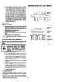
5. Change Engine OII
The best time to change engine oil is at the end of a day's
operationwhen al!dirt and foreignmaterialsare suspended
in the hot oil,
Capacity is1 quart (.94 Iitres). NOTE: DO NOTOVERFILL
Dipstick assembly must be securely tightened into tube at
all times when engine is operating.
15
14
REPAIR AND ADJUSTMENT
a
AIR
SCREEN
b
FUEL CAP
OIL FILLER
CAP/DIPSTICK
Remove oil drain plug to drain engine oil=,Tighten
plug securelybefore fillingwith fresh oilo
Add oil throughthe oil filler cap/dipstick(Fig. 15)o
RECOMMENDEDSAE VISCOSITY GRADES
°F _20'_
°C -29°
0°
-18=
32 °
0°
60 °
16°
80 °
27 °
100°
38°
6. Check Engine Oil Level
NOTE: DO NOT CHECK ENGINE OIL LEVEL WITH ENGINE RUNNING,,
Several minutes alter stopping engine, check engine oil
level with tractor on level ground_ Wipe dipstick (Fig 15)
clean, screw it down tight for a few seconds, remove and
read oil level. If necessary, add oil until "FULL" mark is
reached. (See chart above}_ NOTE: DO NOT OVERFILL.
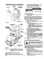
Clean Air Cleaner Element (Rg. 16)
a_ Remove two wing nuts ,_nd remove air cleaner
cover°
b. Remove foam pre-cleaner.
1, Wash pre-cleanerin liquiddetergent andwarm
water to remove dirt.
2_ Wrap pre-cleaner in cloth and squeeze dry.
3. Wipe foam with a light coat of engine oil. Do not
saturate. Squeeze in rag or towel to remove excess oil.
c,, Remove two nuts from top of cartridge_
d,, Remove cartridge and clean air cleaner body carefullyto prevent did from entering carburetor.
e. Clean cartridge by gently tapping on flat surface. If
very dirty, replace cartridge.
f_
Reassemble air cleaner°
NOTE: NUTS HOLDING AIR CLEANER CARTRIDGE
MUST BE INSTALLED WITH FIBER WASHERS
DOWN ON CARTRIDGE PLATE TO PREVENT
DIRT
FROM
ENTERING
CARBURETOR.
TIGHTEN NUTS BY HAND. OVER TIGHTENING
COULD COLLAPSE CARTRIDGE,,
m
OIL DRAIN PLUG
FIGURE
15
,WING
NUTS
AIR CLEANER
COVER
ENGINE OIL
FILLER CAP
AND DIPSTICK
\_
AIR
SCREEN
RBER
WASHERS
FOAM
ELEMENT
NOTE: NEVER RUN ENGINE WITH AIR CLEANER REMOVED,.
8. Clean Air Cleaner and Engine Cooling Fins
TECTION
COMPRESSED
ALWAYS WHEN
WEAR USING
EYE AND
FACE PROAIR.
AIR CLEANER
BODY
FIGURE 16
IMPORTANT:
Air screen and cooling fins (Figs_ 16 and 17) must be kept
free of dirt and chaff to prevent engine damage from overheating. Clean with a wire brush or compressed air to remove dirt and dried gum fibers,.
/
a Remove hood (page 20)°
b Remove air cleaner cover (Fig. 16)o
c_ Remove 3 screws securing air cleaner body (Fig.
17) and remove. (Covercarburetorto prevent entry
of dirL)
d Remove oil dipstick and cover opening to prevent
entry of dirt,.
e. Remove 3 screws from blower' housing and lift
housing off engine (Fig 17)_
TO AVOID DAMAGE TO THE STARTING
SYSTEM,
USE SAE 5W30 OIL WHEN
THE TEMPERATURE
FALLS
BELOW
32°F (0°C),,
RECOMMENDED SAE VISCOSITY GRADES
Determine temperature range expected before next oil
change.,Al!oilmust meet A.P.I..service classification SD, SE
or SF.
16
REPAIR AND ADJUSTMENT
f° Usecompressed
air or stiffbristlebrushto thoroughlycleanengine cooling fins (Fig 17) and air
screen (Fig. 16).,
g, To reassemble, reverse above procedure.
ho Be certain carburetor tube, breather tube, and gaskets are in place (Fig t7).
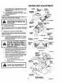
9. Check Muffler
Inspect and reptace damaged mufflerand/or deflector as it
could create a fire hazard ano/or aamage.
/;KET
DER
OR FINS HOT
AS MUFFLER,
CONTACTCYLINMAY
DO NOTTOUCH
CAUSE BURNS.
HEX HEAD
SCREW
BREATHER
TUBE
10. Lubrlcate Pivot Points
FINS
Place several drops of SAE 30 oil at points where metal
parts move against each other, see LubricationChart page
24.
JRETOR
,'TUBE
11o Starting Your Tractor With a Weak Battery
If yourbattery is too weak to startthe engine, itshouldbe recharged. If "jumper cables"are used for emergencystarting,
followthis procedure:
NOTE: YOUR TRACTOR IS EQUIPPED WITH A 12 VOLT
NEGATIVE GROUNDED SYSTEM. THE OTHER
VEHICLE MUST ALSO BE A 12 VOLT NEGATIVE
GROUNDED SYSTEM
SPARK
PLUG
CYLINDER
HEAD
COVER
MUFFLER
FIG URE 17
WASHER
WASHER
POSITIVE
NEGATIVE
MINAL
HEX BOLTS
i
.......
A
!1 _
I! _
I
I
a.
b
c
d
I
LEAD-ACID BATrERIES""GENERATE
EXPLOSIVE GASES. KEEP SPARKS,
FLAME AND SMOKING MATERIALS
AWAY FROM BATTERIES. ALWAYS
WEAR
EYE PROTECTION
WHEN
AROUND BATTERIES.
I
U
|
POSITIVE
CABLE
(RED)
NEGATIVE
CABLE
(BLACK)
-....
|
J
Connect each end o! the RED jumper cable to the
POSITIVE(+) terminalsof each battery(takingcare
not to short against chassis) (Fig 18).
Connectoneendofthe BLACK jumpercabletothe
NEGATIVE (-) terminal of tullycharged battery
Connectthe otherend of the BLACK jumpercable
to the LH side panel bolt (Fig 19) NOTE: KEEP
AWAY FROM GAS TANK AND BATTERY
Disconnectcables in reverse order:
t
LH side panel bolt (Fig 19)
2 Negative terminal of fullycharged battery
3 Positiveterminals
HEX
FIGURE
18
PARKING
BRAKE
"ENGAGED"
POSI_ON
DISENGAGED"
POSITION
"BRAKE"
POSITION
GEARSHIFT
LEVER
.....................................
I
"CLUTCH"
POSITION
17
CLUTCH/BRAKE
"DRIVE" POSITION
FIGURE 19
REPAIR AND ADJUSTMENT
c.
Check that holein throttle lever and hole in plate line
up (Fig. 20 - Insert)_ If holes =A" are not aligned,
loosen clamp screw and move throttle cable until
holes are aligned. Tighten clamp screw.
d. If holes do not align, repeat steps in throttle cable
adjustment°
13. Carburetor Adjustment
NOTE: ADJUSTTHROT__E CONTROL CABLE BEFORE
MAKING ANY ADJUSTM ENT TO CARBURETOR°
a.
With engine offtum higl_speed m_ure screwcl_,kwise closing finger tight ONLY, and turn counterclockwise 1-1/2 turns.
NOTE: THE SCREW SEAT MAY BE DAMAGED BY
TURNING IT TOO FAR CLOCKWfSEo
b
Turn idle mixture screw clockwise closing finger
tight only, and turn counterclockwise1-1/2 turns.
REFER
TO "STARTING THE ENGINE"
PAGE 11.
;I
co Start engine and allow to warm for five minutes,
Make final adjustmentwith engine runningand gear
shill lever in NEUTRAL position.
d_ With throttle control lever in "FAST" position, turn
high speed mixture screw clockwise until engine
runs "rough" and then turn counterclockwise 3/4
turn
e._ With throttle control lever in "SLOW" position, turn
idle mixture screw counterclockwise until engine
runs "rough" and then turn clockwise until engine
beginsto die, Turn idlemixture screwto a point midway between these positions.
L W'dhthrottle control lever in "SLOW" position engine should idle at 1700 RPM, If engine idles too
slow, push throttle controllever above idle and turn
idle speed screw one turn clockwise. Set throttle
control lever at "SLOV'_. Repeat until satistactory
idle is attained
g If engine idles too fast with throttle control lever in
"SLOW" position push throttle control lever above
idle and turn idle speed screw one turn counterclockwise. Set throttle control lever at "SLOW"°
Repeat until satisfactory idle is attained.
h_, High speed stop is factory adjusted.. DO NOT ADJUST- DAMAGE MAY RESULT.
!
I
;!
IDLE
MIXTURE
SCREW
HIGH SPEED
MIXTURE
SCREW
FUEL
LINE
CLAMP
FUEL
FILTER
FIGURE 20
030 (0,762 mm)
FEELER GAUGE
14. Replace Spark Plug
Replace spark plug at the beginning of each mowing season
or every 100 hours, whichever comes first Gap should be
set a 0..030 inch (Fig 21).,
SPARK PLUG
FIGURE
21
12 Throttle Control Cable Adjustment
|
I
|
|
!
!.
A
_
_
.....
DO NOT MAKE UNNECESSARY AD
JUSTMENTS,
FACTORY
SETTINGS
ARE SATISFACTORY FOR MOST AP
PLICATIONS AND CONDITIONS IF AD
JUSTMENTS ARE NEEDED, PROCEED
ASFOLLOWS:.....
a. Make sure air cleaner is clean (see page 16).
bo With engine not running, place throttle control in
"FAST"position (not in "CHOKE" position)_
15. Adjust Valves on Engine
After approximately 200 hours of operation, the engine
valves will require adiustmenL it is suggested that a Sears
Service.Centerdo this work. Correct settings are: IntaKe,.002 (_05 ram), Exhaust - _004 (_1 mm)_
16. Replace In-Line Fuel Filter
BE SURE THERE ARE NO FUEL LINE LEAKS AND THAT
HOSE CLAMPS ARE PROPERLY INSTALLED.
If fuel filteris clogged, obstructingfuel flow to carburetor, replacement is required.
18
a,
With engine cool, remove fitter and plug fuel line
sections that were removed from both ends of fuel
filter (Fig,.20)._
b.
Place new fuel filter in position in fuel lineo
REPAIR AND ADJUSTMENT
BELT
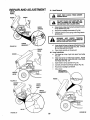
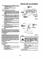
17. Motion Drive Belt Removal
The tractordrivebelt may be replacedwithouttools.Parkthe
tractoron level area. Engage parkingbrake. NOTE: A BELT
INSTALLATION DECAL IS UNDER LEFT FOOTREST°
TRANSAXLE
a, Remove mower, (See page 21),
b, Remove two retainer springs from belt guide
bracket below transaxle pulley, Remove bracket
(Fig. 22).
c Swing belt guides away from belt, toward rear of
tractor (Fig_22).
d Roll belt overtop of transaxle pulleyo
e, Roll belt over engine pulley and off idler (Fig,,23)_
fo Release parkingbrake, Pull belt as far as possible
over top of clutchpJIley+
go Resetparkingbrake, Pullbelt over top of clutchpulley (Fig_23),,
ho Pullbelt out through shift gate to removefrom tractor (Fig=24),
L Install belt by reversingabove procedure,
I
|
!
J i
BELT
ONLY
w'; .E'.E,
T
& REPLACE
RETAINER
SPRING
BELT GUIDE
BRACKET
RETAINER
SPRING
FIGURE 22
ENGINE
PULLEY
LISTED IN THE REPAIR PARTS SECTION OF THIS MANUAL.
BELT
INSTALLATION
DECAL
CLUTCH
PULLEY
18, Fuse Replacement
Replace with 30 amp automotive-type plug-in fuse The
fuse holder is located under the dash,
IDLER
L.H. SIDE
BELT GUIDE
REAR
VIEWED
FROM BOTTOM
OF TRACTOR
FIGURE 23
SHIFT GATE
FIGURE
19
24
REPAIR AND ADJUSTMENT
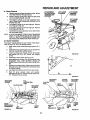
19. Hood Removal
GRASP
HERE
...............
HOOD
iii
u
............
FROM UND
MOWER
DECK.
KEEP FEET
CLEAR
DASH
................
!
iiiiiiiiii
DO :NOT TOUCH HOT MUFFLE:R, ENGINE CYLINDER OR COOLING FINS
AS CONTACT MAY CAUSE BURN.
HOOD
SPRING
FIGURE
25
HERE
Grasp hood at edge nextto dash and open hoodto
full up position (Fig_25).
b_ Disconnect headlightconnection (Fig_28).
GRASP
HERE
26
Gt
HERE
Carefully remove hood springsfrom hinge brackets (Fig. 25)_
d. Lower hood half way and grasp attile bottomof the
grill and at theupper hood edge (Fig,.26). Lilt hood
up, out and away from tractor.
e. Place hood carefully on the ground,,
20. Hood Installation
HOOD
FIGURE
i
a.
c,
HINGE
BRACKE1
I
I
a.
Pick hood up at top of grill and upper hood edge
(Fig 27)..
b
Align hood pivot rod with hinge brac,kets. Rotate
f_x:)d half way down, slide pivot mo in and down
into hinge slots (Fig 27).
c.
d.
e
Open hood to full up position (Fig. 25)°
Carefully reinstall hood hinge springs (Fig 25),.
Reconnect headlight connection,,
f,
Close hood.
HEADLIGHT
CONNECTION
HOOD_\
HOOD
PIVOT
ROD
HINGE
BRACKET
FIGURE
27
FIGURE 28
2O
REPAIR AND ADJUSTMENT
21, Mower Removal
a,
b_
co
do
e.
f,
ATTACHMENT
CLUTCH LEVER
"DISENGAGED"
POSITION
Remove mower belt per instructionsunder"Mower
Drive Belt Removal"through step (c).
Remove retainer springfrom clutchrod; pullclutch
rod out of clutch bracket. (Fig° 29)
Putt retainer springs out of rear suspension trunnionsoRemove rear suspensiontrunnionsfrom lift
brackels (Fig 29).
Pull retainer spring out of rear hinge pin, Remove
rear hinge pin° (F_., 29)°
Pull retainer spring out of front hinge pin.,Remove
fronthinge pin (Fig. 29).
Use lift leverto raise suspension arms. Slide mower
out from under tractor,
LIFT LEVER
PLUNGER
i
LIFT LEVER
"HIGHEST"
POSITION
LIFT LEVER
"LOWEST"
,POSITION
NOTE: tF AN ATTACHMENT OTHER THAN THE MOWER
DECK tS TO BE MOL.INTED ON THE TRACTOR,
THE LH AND R.Ho SUSPENSION ARMS (FIG.
29) SHOULD BE REMOVED FROM TRACTOR.
22, Mower Installation
Your Mower installswithout the use of tools. Raise attachment lift lever (Fig, 30) to itshighest position.
a,
Slide mower under tractor,dischargeguard to R H,
side,.
b,
Install front hinge pin through axle and parallel link
(Fig. 32)., Secure with retainer spring,
install rear hinge pin through mower lift brackets
and parallel link (Fig. 32) Secure with retainer
spring..
Install clutch rod in clutch lever (Fig. 32).
Move attachment liftlever (Fig.,30) forwardto lower
suspension arms, Slide trunnions through lift
bracket holes and secure with retainer springs(Fig.
29)°
Roll belt over engine pulley.,Make sure belt isinside
belt guides (Fig 32). See belt driveschematicdecal
on mower housing
Use attachment lift lever (Fig. 30) to raise mower,
Push lift lever plunger down and position
attachment lift lever to desired cutting height (Fig.
31). Release lift lever plunger
c,
d,
e.
fo
g_
h
FIGURE 30
0
0
0
FIGURE
RETAINER
SPRING
R.H.
SUSPENTION
ARM
CLUTCH
ROD
CLUTCH
ROD
RETAINER
SPRING
RETAINER
SPRINGS
ENGINE
PULLEY
BELT
GUIDES
31
RETAINER
SPRINGS
FRONT
AXLE
\
7
/
REAR /
SUSPENSION
TRUNNIONS
RGURE 29
LIFT
BRACKET
MOWER
LIFT
BRACKETS
HINGE
PINS
21
PARALLEL
LINK
REAR
HINGE
PIN
FRONT
HINGE
PIN
FIGURE 32
REPAIR AND ADJUSTMENT
BELT
EXTENSION
SPRING
23. Mower Drive Belt Removal
ENGINE
IDLER BELT
PULLEY
...._
IDLER
GUIDE
NOTE: MOWER BELT INSTALLATION DECAL LOCATED ON MOWER HOUSING_
SHAFT
ASSEMBLY
REPLACE ONLY WiTH THE BELTS SPECIFIED IN THIS
MANUAL.
LH.
a
f
COTTER
EXTENSION
SPRING
COTTER
PIN
BRAKE__
ROD
"--
Placeattachmentclutchlever in"Disengaged"position (Fig 30)
b,, Move Attachmentliltle_er (Fig 30).forwardto lower
mower to its lowest position_
c_ Roll belt off engine pulley_
d,. Pull belt off both mower deck pulleys._
e._ Springbelt guideaway from idlerpulley and pullbelt
off idler pulley
L Slide belt from under extensionspring.
24. Mower Drive Belt Replacement
a,. Slide belt under extension spring(Fig. 33)_
b,_ Place belt on rear side o! both mandrel pulleys
c,. Sprin_ idler belt guide down and place belt around
rear s_deo! idler pulley
d. Roll belt over engine pulley
e. Make sure belt is inside all belt guides,,
LH. PIVOT
NOTE: WHEN INSTALLING A NEW BELT, EXTENSION
SPRING MUST BE RETURNED TO LOWER END
OF SLOT (ORIGINAL POSITION) ON ROCK
SHAFT ASSEM BLY.
R,H. PIVOT
BRACKET'
25= Mower Drive Belt Adjustment
Yourtractorhas been manufactured withthe abilityto readjustthe rnowerdrive belt to provideyouwith longer belt life,,
FIGURE 33
If the attachment clutch lever travels 4-1t2" (11.43 cm) up
the slot in the dash before spring resistanceis evident, adjustment is necessary, NOTE; CHECK FOR PROPER
SPRING TENSION WITH THE ENGINE OFF AND THE
LIFT LEVER IN THE HIGHEST POSITION.
LIR'
LEVER
a
b
BOTTOM
OF CURL
E_
Lower the mower deck for easier access,.
Using (2) 7/16"wrenches, removethe bolt, nut & DShaped washers (Fig 33- inset).
c. Move extension spring from lower end of slot to upper end in rockshaft assembly and install bolt, nut &
the D-Shaped washers.
d Tighten bolt and nut to secure the D-shaped washers (flat side down)..
26. Level Mower Housing
BOTTOM
OF CURL
Adjustthe mower while tractor is parkedon level ground or
driveway. Make sure tire pressure is correct, fl tires are over
or under inflated, you will not properly adjust your mower..
SIDE-TO-SIDE
LINE
FIGURE 34
a.
__
SIDE TO SIDE'_L-'v'_'_PJ
ADJUSTMENT
TRUNNION
Depress lift lever plunger and use lift lever to raise
mower to maximum cutting height (Fig. 31),
b. Measure heightfrom bottomof cudto groundline at
front of mower. Distance"A" shouldbe the same on
both sides (Fig, 34),
c. If distance "A"needs to be changed, snap out access hole cover on L.H, side above footresL Use
11/16" wrench on nuts "B" and "C" at side-to-side
adjustment trunnion(Fig=,35),.
d. To raise left side of mower, loosen nut "B" and
tighten nut _C",
e To lower left side of mower, loosen nut "C" and
tighten nut "B"..
NUT "C"
_
/
_ i
NUT "B"
_
J
FIGURE
MOWER ADJUSTMENT
35
22
REPAIR AND ADJUSTMENT
NOTE: ONE ROTATION OF ADJUSTMENT NUTS IS
EQUIVALENT TO APPROXIMATELY 3/16" (4.75
ram) HEIGHT CHANGE°
f_
Be sureall nuts are securely
tightened..
Replace
cover.
g_
FRONT-TO-REAR
REAR
SUSPENSION
ARM
\
\
,\
MOWER ADJUSTMENT
a.
Toobtainthebestcuttingresults, yourmowerhoustrig should be adjusted so the front and rear flange
distance"D"(Fig. 36) is 112"(!327 cm) _wer infront
when the mower is positionedin the hignestcutting
position.
NOTE: MEASURE DISTANCE "D"FROM GROUND LINE
TO BOTTOM OF CURL ON RIGHT REAR
FLANGE AND COMPARE TO DISTANCE"D" AT
BOTTOM OF CURL ON RIGHT FRONT FLANGE.
BOTTOM
OF CURL
\
ID
REAR
SUSPENSION
TRUNNION
b.. To raise rear of mower, loosen nut "E" on both rear
suspension arms. Screw both nuts =F_ up EQUAL
NUMBER OF TURNS (Fig..37)..
co When distance =D" is 1/2" (1o27cm) lower at front
than rear tightennuts "E'..
d. To lower rear of mower, loosennut "F"on both rear
suspensionarms an EQUAL NUMBER OF TURNS
(Fig. 37).
e. When distance "D" is 1/2" (1.27 cm) lower at front
than rear, retighten nuts "E.
NOTE: WHEN ADJUSTING REAR SUSPENSION TRUNNIONS, ALWAYS ADJUST BOTH EQUALLY SO
MOWER WiLL STAY LEVEL°
GROUND
LINE
FIGURE 36
NUT "E"\
REAR
TRUNNION
REAR
SUSPENSION
ARM
LIFT
BRACKET
NUT "F"
27. Storage
Remove mower from tractorfor winter storage. When mower is to be stored for a period of time, clean itthoroughly,remove all dirt, grease, leaves, etc. Give blades and underside
of housing a good coat of grease or rust preventative.Store
in a clean dry area.
A. Fuel System
FIGURE37
it is importantto prevent gum deposits from formingin essontial fuel system parts such as the cart_Jretor,fuel filter,
fuelhose, ortank duringstorage Also,experience indicates
thatalcohol blendedfuels(calledgasoholorusingethanolor
methanol) can attract moisture which leads to separation
and formationof acids during storage Acidicgas can oamage the fuel system of an engine while in storage. To avoid
engine problems, the fuel system shouldbe emptied before
storageof 30 days or longer.
D. Battery
I1'
&
B. Engine O11
IIIII1'1I'
LEAD-ACID
BATTERIES GENERATE
EXPLOSIVE GASES. KEEP SPARKS,
FLAME AND SMOKING MATERIALS
AWAY FROM BATTERIES. ALWAYS
WEAR
EYE PROTECTION
WHEN
AROUND BATTERIES.
I ....................
Drain (with engine warm) and replace with clean engine oil,
(See chart page 16)
C. Cylinder
1. Remove spark plug.
2. Pour one ounce (29_5 ml) of oil through spark plug
hole in to cylinder.
3. Turn ignition key to "START" position for a few seconds to distribute oil.
4o Replace with new spark plug..
1_ Prior to storage, clean terminals and top of
battery.
2.. Disconnect BLACK battery cabte from
negative side of battery.
3,, Disconnect RED battery cable from positive
side o! battery.
4. Position cables down and away from battery,
E. General Cleaning
Clean engine, battery, seat, finish, etc of all foreign matter.
23
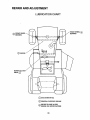
REPAIR AND ADJUSTMENT
LUBRICATION
Q
CHART
FRONT' WHEEL
BEARING
FRC
BEARING
J
I
!
Q
ENGINE
MOWER
PIVOT Q
Q
SAE 30 MOTOR OIL
Q
GENERAL PURPOSE GREASE
Q
REFER TO PAGE 16 FOR
ENGINE OIL SPECIFICATIONS
24
Q
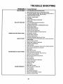
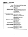
TROUBLE
PROBLEM
SHOOTING
Cause/Remedy
WILL NOT START
Push Clutch/Brake Pedal into Brake position
Move Attachment Clutch Lever to "Disengaged" position
Fill Tank with Gasoline. Check Fuel Line and Carburetor (clean if
necessary). Replace Fuel Filter_Use Fresh Fuel
=P Check Fuse for fault and replace
Recharge or replace Battery
,=," Check Wiring
=r Replace Spark Plug(s) and adjust gap
=r. Adjust Valves
WILL NOT TURN OVER
=r
Push Clutch/Brake Pedal into brake position
Charge or replace Battery
w,
Move Mower Clutch Lever to "DISENGAGED" position
w
Replace ignition Switch
Replace InterlockSwitch(es)
Replace Solenoid or Starter
Check for fault and replace Fuse
Check all Wire Connections and "Ground" Points
ENGINE CUCKS BUT WON'T START
HARD TO START
w.
Clean Battery Terminals
w.
w.
Replace Starter or Solenoid
Charge or Replace Battery
Check Wire Connections and "Ground"Points
=r
Ptace Throttle Contro! in =FAST" position and run starter several times
to clear out gas
Remove Air Filter and clean
f
Replace Spark Plug(s) and adjust gap
Recharge or replace Battery
Check the Wiring
Drain Fuel Tank and Carburetor. Use Fresh Fuel.=Replace Fuel Filter
=-. Make necessary adjustments to Carburetor
Adjust Valves
=r
ENGINE MISSES OR LACKS POWER
Major Engine Overhaul
Shift to a lower gear or reduce load
='_ Drain Gas Tank and Carburetor° Use Fresh Fuel
=r. Remove and clean Air Cleaner
w-
Make necessary Carburetor adjustments
Clean Air Screen
_"
Add or change oil
,r
Replace Spark Plug(s) and adjust gap
w _ Check for loose wires
ENGINE OVERHEATS
w.
Replace Fuel Filter
wr
Adjust Valves
w.
,r
Major Engine Overhaul
Shift to lower gear or reduce load
Clean Air Screen
w = Add or change oil
w. Clean Engine Cooling Fins
,r
,r
Remove and clean Muffler or replace
Remove and clean Air Filter
25
TROUBLE SHOOTING
NO UGHTS
WON'T CHARGE
mP
Use fresh fuel and adjust Carburetor
Drain and replace oil for propertemperature
_r
Check Fuse, Switch and Wire Connections_Replace Headlight Bulbs
Replace Switch
aP
Check Fuse for fault and replace
_P
_P
ENGINE WILL NOT SHUT DOWN
WHEN OPERATOR LEAVES SEAT
Replace Battery
Replace Regulator
Replace Alternator
NOTE: This tractor is equipped with an operator presence sensing
system..Any attempt by the operator to leave the seat wi!h the engine
funningand the mower clutch engaged will shut down the engine.
w.
Check all Wire connections
Check Seat Switch
Check Operator Presence Relay
UNSATISFACTORY
MOWER PERFORMANCE
UNEVEN DISTRIBUTION
OF CUPPINGS
Place Throttle Control in "FAST" position
Check air pressure in Tires
="
Check front-to-rear and side-to-side Mower adjustment
Use a slower ground speed
Replace Mower Blades
=_
Reinstall Mower Blades with Sharp Edge down
,=" Replace with proper Mower Blades
Readjust Mower Drive Belt
=r Clean undersideof Mower Deck
MOWER BLADES WILL NOT ROTATE
Correct Clutch mechanism interference
,=," Install new Mower Drive Belt
=r
Adjust Mower Drive Belt
=_" Replace frozen Mandrel
=r Replace frozen Idler Pulley
EXCESSIVE MOWER VIBRATION
_"
Replace bent or unbalanced Blades
==" Replace Mandrel Replace Deck
WINDROWING STRIPPING OR
DROPPING OF GRASS CLIPPINGS
,==r
Set Throttle for maximum engine speed
Let grass dry out
Clean underside of Mower Deck
==," Readjust Mower front-to-rear and side-to-side
Replace Blades
UNEVEN CUT OR SCALPING
Readjust Mower front-to-rear and side-to-side
=r
Replace Blades
Replace bent Mandrel(s)
.....................................................................
26
iii
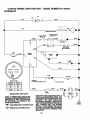
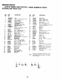
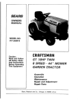
12 HP 38" RiDiNG LAWN TRACTOR - - MODEL NUMBER 917.254611
SCHEMATIC
_
°
12V
olll,o
I
RED
INTERLOGK
SWITCHESt -
-
1
!
J
v
I
I
(CLUTCHOFF)
pEDAL
UP)
- \
I
AT_MENT
CLUTCH
J
CLUTCH/BRAKE
i
I
t
BLACK
WH_E
!
.J
SOLENOID
BLACK
SEATSWITCH
(NOTOCCUPED)
FUSE
©
30/_P
IGNITION
SWITCH
B
SPARK
d
BLACK
e-----
BLACK
DEODE
CHARGING
eX){L
IGNITIONSWITCH
POSITION
III
I
3 AMPSDC
AT3600RPM,BATTERY{NLINE
\
\
20 VOLTSAC (MIN)
_RCUIT
IIIIII
ON
_L
START
i_S
UGHT
WIRING INSULATED CLIPS
NOTE: IF WIRING INSULATED CLIPS
OR CABETIESWERE REMOVED FOR
SERVICING OF UNIT, THEY SHOULD
BE REPLACED TO PROPERLY SECURE YOUR WIRING.
NON-REMOVABLE CONNECTIONS
"O"
REMOVABLE CONNECTIONS
swiTcH
,ou,,,,=o,,,,o,w,,,.
SPECIAL ALTERNATOR SYSTEM. THE
LIGHTS ARE NOT CONNECTED TO THE
BATTERY,
BUT HAVE THEIR OWN
ELECTRICAL SOURCE. BECAUSE OF
THIS,THE BRIGHTNESS OFTHE LIGHTS
WILL CHANGE WITH THE ENGINE
SPEED. AT IDLE SPEED, THE LIGHTS
WILL DIM. AS THE ENGINE IS SPEEDED
UP, THE LIGHTS WILL BECOME THEIR
BRIGHTEST.
27
I
_1
o
'
\
_/
\u
u)-----"
.=_.,_
I
t_
CHUB
GROU/_D
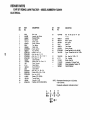
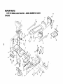
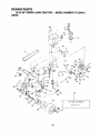
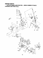
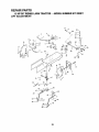
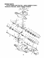
REPAIR PARTS
12 HP 38" RIDING LAWN TRACTOR - - MODEL NUMBER 917.254611
ELECTRICAL
8
32
_33
3O
32
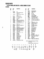
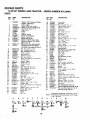
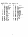
REPAIR PARTS
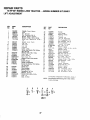
12 HP 38" RIDING LAWN TRACTOR-ELECTRICAL
KEY
N O o
t
2
fo
co
PART
NO,
DESCRIPTION
7662J
124108X
Bulb, Light
Harness, Light
MODEL NUMBER 917.254611
PART
NO.
DESCRIPTION
2B
72240460
29
30
3t
109081X
Bolt
Rd. Hd. Sq. Nk. 1/4
7-1!12
Solenoid
109787X
Bezel • tgnition
109788X
7192J
Nut, ignition
Cable Tie
tO5687X
Tube. Plastic
Socket
3
4
5
6
7
8
9
t0
1t
12
!3
14
15
16
17
18
19
20
2!
22
23
126399X
109310X
110712X
IO4445X
7603J
109596X
STD365402
108824X
STD551125
STD541225
STD541425
108423X
11050400
7 t 93
5114J
109553X
4207J
STD522507
STD551025
STD541025
Harness, Wiring
Key, Molded
Switch, Light
Sw_tch. Interlock
Tray, Battery
Clamp, Hose
, Switch. Ignition
Fuse, 30 Amp
* Washer. Lock. 1t4
, Nut. Hex Jam 114 20
•Boft, Hex, 1/4
20 x 1/2 Gr. 5
• Nut, Keps 114 20
Cable Assembly
Washer Lock. Ext. Tooth, 1/4
Cover, Terminal
Cable. Battery
Swttch,lntertock
Cable, Battery
- Bolt, Hex, t/4
=20 x 3/4
• Washer 9132 x 5/8 x 16 Ca.
* Nut. Hex tt4-20
24
25
26
27
121265X
102476X
123t98X
STD551125
Battery, 12V., 25 Amp
Terminal Guard
Wing Nut 1t4-20
• Washer, Lock HW Helical Spring
STD522505
KEY
NO.
32
33
34
35
36
t 21305X
STD601005
74641008
37
3B
39
41
"'"
NOTE:
Switch,
. 20 x
Plunger
• Screw,Tap Hex Hd: #10 x 24 UNC
Screw - Slotted Pen Hd. No. 10-32
112
73951000
4171R
Nut
Keps No. 10-32
Clip . insulated
x 112
121264X
1 ! ! 50400
Battery Caps Set
Lockwasher 1/4 Internal Tooth
101539X
126795X
Sheet, Instruction,Tractor, 15°
Owner's Manual
All component dimensionsgiven in U,S, inches,
! inch = 25.4 ram.
"STANDARD HARDWARE--PURCHASE LOCALLY
A
B
C
D
x
REPAIR PARTS
12 HP 38" RIDING LAWN TRACTOR - - MODEL NUMBER 917.254611
4O
CHASSIS
22
55
6O
61
L
38
D
30
56
o
A
G
F
31
33
15
13
A
37
A
36
REPAIR PARTS
12 HP 38" RIDING LAWN TRACTOR - - MODEL NUMBER 917.254611
CHASSIS
KEY
NO,
PART
NO.
DESCRIPTION
!
2
121075X
t 749061 2
3
174906t6
Seat
Screw. Hex Washer Thd, Rol!
3t8-t6 x 314
Screw. Hex Washer Thd. Ro!hng
3t8 16 t
Bracket-P_vot. Seat
Bolt. Shoulder= 5' 16 18
Nut Crownlock 5t16 18
Spr_ng, Seat
Fender
Bolt, Fin Hex 318x 16UNC x 3/4
Screw, Spidedock Hex #Bx I/2AB
Nut, Crowniock 3/8 16
Screw. Hex Washer Thd Rol! 3 8
16 x _ 2
Brackel. Fender
Bolt, Fin Hex 1/4 x 20 UNC x 1/2
Footrest. L H
Footrest. R.H
Bott, RdHdSQNk 318 X 16 UNC x 3/4
Washer, Lock, Hvy Helical Spring
Bolt, Fin Hex 318 x 16 UNC x 1
Washer 13/32 x 13/16 x t2 Ca.
Lens Assembly
Washer }3 32 x 3.4 _ 10 Ga
Cap, Spring
Pad, Footrest
Decal, 12 HP
Rivot, Ratchet, Nylon
Shield, Hood, Heat
Deflecior, Heat
Hood Assembtv
Bushing. Snap
Nut, Crownlock
3t8 x 16 UNC
4
.5
6
7
8
9
10
t I
12
t 055 t 3x
! 05529X
73680500
124181X
109872X
STD523707
17030808
73680600
} 7490608
13
t4
15
16
!7
t9
20
2t
22
24
25
26
27
29
30
3t
32
33
34
109873X
STD512505
105465X
105464X
STD533707
STD551125
STD5237t0
19131312
124029X
19131210
124238X
105466X
t24493X
t 22933X
I24027X
123665X
124025X
_ 21248x
STD5414,37
*
•
•
•
•
*
DESCRIPTION
KEY
NO.
PART
NO.
35
36
37
38
39
40
4t
42
43
44
45
46
47
48
49
50
51
52
53
54
55
56
57
58
59
60
61
62
63
64
65
66
67
124479X
t2435SX
121306X
t24294X
125880X
t24492X
49003
105809X
109199X
19132012
f 2 t 440X
12144tx
2751R
19131614
72t 70410
123976X
t 2125 t X
121250X
121249X
t 21246X
124489X
124490X
123913X
123914X
124040X
123915X
t05037X
121144X
STD5250!0
19171912
106974X
750211
STD551150
NOTE:
_
B
2
;
C
5
_
9
24
D
E
F
G
H
_1°
_!4
_17
_17
_3
_19
_
11
1_
34 _48
L
J
Chass,s
Drawbar
Assembly
Pan • Seat
Deca|
Fender
Decal,
Decal,
Grill, Craftsman
CtutchlBrake
Decal, Chassis, 5 Speed. 38"
Decal, V-Belt Ground Drwe
Washer
13/32
x _-1t4
x 12 Ga.
Gutde
Guide
Belt.
Belt,
Lower.
Lower,
44
_50
L,H.
R.P!.
Chp
Washer 13/32 x 1 x !4 Ga.
BOlt, RdHd 114x 20 x !-1/4
Nut, Hex, Lg. Flange, Loc.
Strip.
Foam
Spring, Seat, Compression
Spacer,
Bracket.
Split
Switch
Mount
Decal Stnoe Hood L.H.
Decal Stnpe Hood R.H.
Bracket, Pivot, R.H.
Bracket, Pivot, LH.
Spring, Extension
Grill
Foam, Stript8
Bolt. Shoulder
• Bott,Fin Hex 1/2 - 13 UNC x I Gr. 5
Washer 17/32 x 1-3/16 x 12 Ca.
Decal, Caution
Decal, USA
• Washer, Lock Hvy=Helical Spring
HARDWARE
M
,PURCHASE
N
'_ 2°
_
Eng. Pulley,
Eng. Pulley.
AUcomponent dimensionsgiven in U.S. inches.
1 inch= 25.4 ram.
"STANDARD
A
Washer, Black, Nylon
21
(_) 11
O"
LOCALLY
REPAIR PARTS
12 HP 38" RiDiNG LAWN TRACTOR - = MODEL NUMBER 917,254611
DRIVE
HH
•
i
K
65
Spark
32
Arresler
REPAIR PARTS
12 HP 38" RIDING LAWN TRACTOR - - MODEL NUMBER 917.254611
DRIVE
KEY
NO,
2
3
4
5
6
7
8
9
10
11
12
13
14
15
16
17
18
19
20
21
22
23
24
PART
NO+
DESCRIPTION
KEY PART
NO+ NO,
DESCRIPTION
126126X
'
Engine, 12 HP, Tecumseh, Model
Number 143+406152
48
49
123766X
123789X
Pu|ley, Idler
Arm, Idler
105731X
Pulley+
50
STD5237!5
13200300
Elbow
51
105709X
Spring,
52
1lOBI2X
Washer Hardened
53
54
55
56
57
12000039
105710X
STD5612t0
58
tO688BX
5116
59
73350600
Spring,
Rod, Brake
Nut
Jam 3/B t6
Keeper, Belt, Engine
Washer !1/32 x 11/16 x 16 Ga+
Screw, Hex Washer Thd. Rolling
3/8 X 16 x 1+1/2
Washer, Lock, HW. Helical Spring
Transaxle, Tecumseh 5Speed,
60
19131316
Washer
61
62
63
12563BX
124236X
122424X
Rod Brake,
64
8883R
Cover
Pedal
65
12t749x
Washer
25f32
143+920037(See pages 40 and41)
66
STD551143
43
44
46
46
47
90 3/8 - 18 NPT
• Washer, Lock, Hvy Helical Spring
74770720
Bolt, Hex 7/1620
V+Beh, Drive
t25907X
122983X
2949R
x I ,I/4
Muffler
Gasket
101326L
Deflector°
123528X
Screw, Hex Head Cap
STD561131
" Washer.
121218X
STD55103t
17490620
STD561
t25
122372X
STD523727
STD541437
73680500
123666X
12000028
109167X
STD523710
•
Muffler
Lock
123662X
Hex
3/B
16 x 1 1,2
Return,
Clutch
Ring. Klip
Link, Clutch
• Pin Cotter
i/8
Bracket+ Clutch
Rod. Brake
123102X
110437X
Cap
13/32
x 13
Park_g
Plunger
STD571810
"Prn.
Roll
x 1 1 4 x 16
3t16
120183X
123583X
Key.
Nut, Crownlock 5/16 x 18
69
13280324
Nipple, Pipe 3/BNPT 3"
Pulley,
70
71
59192
65139
Cap Valve
Stem. Valve
72
73
74
75
3588R
106108X
109501X
2751R
Tire, Rear
Rim Assembly, 8", Rear
Spacer
Clip, Fuel Line
76
77
78
79
12000001
t2152OX
STD533707
110422X
Transaxie
x I
Hex Washer
x 3/4
Battery
Belt, L H
Thread
Rolhng
Square,
2,,5 x .1845A1865
ERing
Strap,
Torque
Transaxle
' Bolt. Carnage
3/8,16
x 3/4
Sprlng
Brake
BO
t05706X
Beanng
• Nut, Crownlock 51t6x 16
81
Reta+ner Belt
82
124379X
Strap
Locator
Keeper+
Belt, R H
' Bolt, Hex 318+t6
x 3/4
Washer
25132
x 1 5/B x 16 Ga
Knob
Shift
Rod. Sh+ft
123205X
17030808
71040412
105701X
5TD661210
Bolt
Hex I/4.28
x 314
Washer
, Shift Plate
" Cotter
Pin, 1/8 x t
19151216
Washer
!5/32
I04777X
Retainer Belt
t 7490612
Screw+
19131312
16 x 3!4
Washer 13/32 x 13/16 x 12 Ga
iO5730X
1 O907OX
4470J
Keeper,
Retainer
Spacer
123674X
Idler
Hex
x 3/4
Washer
Belt.
Belt
x
Thd
16 Ga
Rolling
3/8
Engine
83
84
105700X
108B43X
Screw
Sp+der
X 112 ABTPS
Sprmg
Plate. Sh_ft
85
86
87
19091210
11050600
7t62J
Washer
9/32
x 3/4 x 10Ga
Washer
Lock
Ext
Tooth
3/8
Tube
Tire (not furnished
with
88
12185tX
Spark
89
90
91
92
93
94
STD551062
74760540
104757X
STD580025
126629X
STD541437
95
+--
Flat
B
C
_19
D
E
F
G
_t8(_3(_43
H
(_11
33
Lock
No 8+18
tractor)
Arrester
• Washer 21f32 x 1 x 16 Ga+
Bott, Hex 5/16x 16 x2-1/2
Cap, Hub
" Key, Woodruff #9 3/16 x 3/4
Decal, Craftsman/Tecumseh 12 HP
* Nut, Lock Hex w/wsh ins 3/8 - 16
See Key No. 72, Page 43
"STANDARD
NOTE:
Ga
Bearing, Nylon
STD54t437
123770X
123663X
x 3,4
Ga
x 1
Retainer
Spnng
Clamp
"Bolt.
Hex 5/t6,18
A
16 x ;6
Shaft Foot Pedat
4921H
106190X
STD523107
STD523707
121748X
106933X
x 34
68
Screw.
5116.18
Support.
Keeper.
10817!X
'Bolt,
67
Hex 3/8+16 3/8
x 2-3/4
•" Bolt,
Nut, Crownlock
16
Ring, Retainer
Bracket
Transaxte
"Bolt,
Hex 3/8+16
17490612
25
26
27
28
29
30
31
32
33
34
35
36
37
38
39
40
41
42
Engine
+ STD
HARDWARE,PURCHASE
LOCALLY
Arl component dimensions given in U S. inches.
1 inch = 25.4 ram.
J
_9)18
K
L
M
_86
53
34
REPAIR PARTS
12 HP 38" RiDiNG LAWN TRACTOR - - MODEL NUMBER 917.254611
STEERING AND FRONT AXLE
KEY
NO.
PART
NO,
DESCRIPTION
t
2
3
4
5
6
123o42Xo12
74180512
7351050o
1o9816x
124434X
1772o410
Dash
7
8
9
lo
126684X
1244t7x
124466XOll
17490608
Screw
Truss
Hd
Nut - Keps 5tt6
. Nytlner,
Snap In
Control
. Throttle
5/1618
x 3/4
18
Screw, Hex Thread Cut
114x20xS/8
Washer5/Bx l/4x16Ga+
Boot, Steering Shaft
278H
57
106732X
58
59
60
6_
63
59192
65t 39
106222X
121749X
59904
F,tt,ng
Grease
Bearing
Flange
R,m
6
Front _lnc
2 Each Key
No
56_
Cap
Valve
Stem
Valve
Tile, Front
Washer
25 32 x 1 1 4 x 16 Ga
Tube
Front tNot fumtshed
w,_h
tractor3
64
121748X
65
STD551231
Shaft, Support
66
110307X
Stop, Mower Clutch
Khp Ring
Washer.
Hardened
68
69
_9272016
121232X
Washer
27 32
Cap, Spindle
22
STD611005
23
24
108456X
124373X
124036X
17490612
Screw
Hex Self Tap
No
t0 16 x I 2 Type ABTPS
Decal
|nstruct_on
tJperatmg
Bush+ng
Steering
8racke!
Steering
Screw
Hex Washer
Thread
3 8 16 x 3 4 Type TT
Bearing
Thrust
Gem
Sector
32
33
34
Rothrhq
TT
9040H
Screw,
30
31
5 16 18 x 1 2 Type
Gear. Ptnlor,
56
71 O7O410
124030X
29
Rear
55
!9
6266H
124034X
124035X
t 2000029
57O79
124038X
122819X
104757X
SaQdle
Spmd{e
Slmndle
20
28
Support
Saddle. Front
Bolt
Hex 5!8 I t _ 3 3 4
Axte
F+ont
Spacer
Bear=ng
Fronl Axle
Nut
Lock Flange 5 8 I 1
Screw
He_ Washer
Threa,3
tO5656X
105654X
Lockwasher 1/4
27
105664X
74761060
t05669X
110438X
73901000
17490508
53
STDS51125
26
Support
38
39
40
41
42
43
Adapter
18
25
Shaft, Pitman
!O5663X
105715X
t 20754X
19131416
76020412
STD551137
73610600
Thread
17
5479,1
t24033X
37
46
47
48
49
50
5t
52
Hd
100710L
STD541350
1007 t 2K
100713N
100711L
21
36
Rothng 3,8 t6 x 1 2
Chp
Insulated
Decal
Steer,ng
Whee+ Cap
insert
Steering
Wheel
Nut
Hex Jam Lock
1 2 20
Washer
2-1t4
Whee|
Steering
Washer
t3
15
16
DESCBIPTION
124037X
3366R
Hex
2751R
14
PART
NO
44
45
Saddle
Screw
11
12
125879X
KEY
NO,
Stee,ng
Socket
Whee+
Hex
54
I/4
x 20 x 5/8
Bumper, Hood
Plug, Button
Shaft,
Steering,
Screw,
Special
124032X
Ro_hng
Rod
T+e
Bushing
_Nasher
13 32 x 7 B • 16 G_
P,n
Cotter
! 8 x 3 4
" Washer
Lock 3 8
Nut, Fin Hex 316 x 24 UNF
bnk
Drag
L H
R H
Washer 25/32 x 1-5/8 x 16 Go,
• Washer
Lock.
lnt Tooth
x
5 16
t I 4 x +6 Ga
Lower
Cap, Hub
*STANDARD
NOTE:
A
Bea6ng
B
C
D
F
)1o
®3
35
HARDWARE
PURCHASE
LOCALLY
All component dimensions given in U,Soinches
1 inch = 25,4 mm
G
H
_2
65
®3
REPAIR PARTS
12 HP 38" RiDiNG LAWN TRACTOR - ,. MODEL NUMBER 917.254611
LiFT ADJUSTMENT
31
28
36
\
24
REPAIR PARTS
12 HP 38" RIDING LAWN TRACTOR - - MODEL NUMBER 917.254611
LIFT ADJUSTMENT
KEY
NO
t
2
3
4
5
6
7
PART
NO,
124429)(
IO6932X
106451X
73680600
t06452X
19171516
17021008
8
9
I0
11
12
13
14
106447X
123549X
109202X
101335K
124028X
123487X
17490612
15
16
19091416
122795X
121794X
124031X012
19211416
STD58i062
!22365X
122512X
17490412
17
18
19
20
21
22
23
24
25
26
27
28
29
30
31
105736X
5320R
120183X
105839X
105838X
STD551025
122507X
I05751X
DESCRIPTION
KEY
NO,
PART
NO,
Handle C_utch Mower
32
33
122364X
125631X
Plunger
Gr=p Handle
34
35
36
4939M
110029X
110447X
Retainer
L,nk bh
Trunnion
37
1t0448x
3B
39
40
4 1
121598X
IO5848X
121599X
106308X
42
STD54t050
43
44
45
9135R
19171516
4921H
Knob
Bolt Shoulder
Nut, Crownlock
Bracket
Sw_tch
3!8 16
Interlock
Washer 17132x 15/16 x 16Ga.
Screw
Hex Tapping
No
! 2
Support
Lever
C_utch
Cap Fuel
Tank
Fuel
Lme
Fuet
Grommet
Clamp
Hose
TO 24
x
DESCRIPTION
Retainer
Spring
Washer
17 32 x 15 16
Retainer
Spring
Bracket
Suspension
Bracket
Bellcrank
Bolt
Hex 3 8 !6 x 3 4
Screw, Hex Washer Thd, Rolling
46
!05864X
47
106444x
Washer 9F32x 7t8 x 16Ga
48
STD523707
Panel
Cover
Panel
49
50
t09728X
STD5612t0
51
52
124444X
19131410
53
54
55
122514X
105767x
124446X
56
72 140606
Spring
Screw
1/4 --20 X 3/4
Shield,
Heat
57
59
t O8236X
_ _0739x
Bracket
Clip, Insulated
60
73980600
Bearing,
6_
73360700
62
73710700
Washer 21/32 x 718x 16 Ga.
E R_ng
Button, Plunger
Spring, Compression
Screw,
Hex
Washer
Thd
Rolling
Nylon
Receptacle,
114 Turn
L_fl
L_nk Lift Adlustable
Arm
Suspension
R H
Bolt
Shoulder
38
16
Arm
Suspension
L H
Trunnion
Lift
Lower
Nul
Hex 1 2 13
3/8 x 16 x3t4
Dash
L H
Access
Dash
R H
Srpmg
o
= 16 Ga
Bettcrank
Assembly
Pin Cotter
t 8 _ 3 4
Rod CIJIch,
Primary
Washer
1332
. 7 8 x !OGa
F_od Assembly
Lever
Pm
Groove
E wtens_on
3 8 16 x 3 4
Swmtch
Washer
Sprnng
Nut
Flangetock
3 8 _6
Nut
Hex .Jam 7 16 20
Nut
Crgwnlock
7 _6 20
Retainer, 1/4 Turn
Washer
Shaft
Stud,
9132 x 5t8 x 16 Ga
L_ft
"STANDARD
1/4 Turn
NOTE:
A
B
C
D
E
HARDWARE
All component dimensions
1 inch = 254 mm,
F
23
m4
Qs9 '
37
PURCHASE
LOCALLY
given in UoS inches,
REPAIR PARTS
12 HP 38" RIDING LAWN TRACTOR - - MODEL NUMBER 917,254611
38" MOWER
38
REPAIR PARTS
12 HP 38" RIDING LAWN TRACTOR - - MODEL NUMBER 917.254611
38" MOWER
KEY
NO
1
2
3
4
5
6
7
B
9
10
1!
12
13
14
15
16
t7
I8
19
2O
21
22
23
24
25
26
27
28
29
3O
31
32
33
34
35
36
37
PART
NO
DESCRIPTION
KEY
NO
106085X
V-Belt
121259X
84 t 7J
73680600
19111216
72140505
105896X
1 t 0452X
Housing
Runner,
R H.
Nut, Crowntock
318., 16
Washer
11t32
x 314 x 16Ga
Bolt. Cerr,. 5t16 -, 18 x 51B
Bracket.
Deflector
Puahnut
1 O6734X
106735X
tO6736X
105814X
1 O5304X
105662X
Spring_ Deflector
Rod - Hinge
Deflector
_ Shield
Decal,
V,IBelt Mower
Cap
Link. Parallel
10574-4X
105872X
109835X
STD523707
73680500
10959BX
109597X
Pin
Hinge. Front
Stop.
Link
Pin , Hinge, Rear
* Bolt 31816
x 3/4
Nut, Crown!ock
5/16
Bracket,
Lift
R H
Bracket,
Lift. L,H
STD533107
*Bolt.
3713J
tO9503X
109504X
Cart
5/16,18
Drwe
18
x 3/4
Decaitlnstruction
. Caution
Support. Arm
Stop, Deck. Front
Decal , Safety Standard
Not Serviced
Guide Belt
Bolt 318-, t 6 x 2
Arm° Idler
Spacer - Retainer
Pulley _,idler
Washer. Wear 1tt6
Keeper. Belt
Mandrel Assembly
Plate, Support Mandrel
Screw, Hex Washer Hd 3/8 x 16 x 7/8
Screw, Hex Washer Hd 3/8 x 16 x 1-1/4
126756X
74760632
123553X
106902X
! 2131BX
1065!3X
102_9X
121687X
1_6L
17490614
17490620
PART
NO
DESCRIPTION
38
39
40
41
42
43
121263X
19132012
STD551137
STD623715
108250X
108235X
44
45
46
47
48
49
50
5_
4921H
6404J
124066X
76020616
tO8247X
72140606
108243X
lOB241X
Spring Retainer
Spacer 1/2 x 9/16
Rock Shaft Assembly
Pin. Cotter. 3/16 x I
Rod. Brake. Primary
Ball. Cart. 318-16 x 3/4
Bracket. Pivot, R H
Bracket, Pivot, L H
52
53
54
55
56
57
58
59
60
61
62
63
64
65
66
67
68
69
70
71
72
73
105B57X
l OB673X
_0657BX
I106463X
!08249X
t06456X
t O0672K
t00673L
t913t614
74760688
7631J
t9111016
72140610
121343X
t22314X
STD560907
72110506
74760412
109893X
73680400
11 O445X
STD551037
Bracket. Suspension, Rear. R H
BrackeL Suspension. Rear_ L H
Brake Assembty
Rod Brake. Secondary. LH.
Rod Brake. Secondary. R H
Bracket_ Brake. Pivot
Spacer_ Brake
BrackeL Support
Washer 13t32 x 1 x 14 Ga
Boll 3!8-16 x 5-1t2
Runner L H.
Washer 1 t/32 x 5t8 x 16 Ga
Bolt, 3tB-16 x 1-1t4
Decat Warning
122215X
Blade
Washer 13/32 x 1 1/4 x 12 Ga
• Washer, Lock 318
. Bolt, Hexo 31824 x 11112 Gr 5
Spring, Extension
Rod Clutch, Mower
Spacer
• Pin. Cotter, 3/32 x 1/2
Bolt. Carriage 5/16-18 x 314
Bolt Ftex 1/4-20 x 3/4
Washer, Special
Nut. Crownlock 1/4.20
Plate, Support, Mandrel, LH.
• Washer 13/32 x 13/16 x 16Ga_
Mower Assembly, Complete
* STANDARD HARDWARE - - PURCHASE LOCALLY
NOTE:
A
B
C
O
E
F
G
61
®5
19
®19
_4
_19
All component dimensions given in U,S, inches.
1 inch = 25.4 ram,
H
36
J
K
37
L
!8
M
64
69
_9
_4
_4
_70
71
39
REPAIR PARTS
12 HP 38" RiDiNG LAWN TRACTOR - - MODEL NUMBER 917.2546111
TRANSAXLE PEERLESS- MODEL NUMBER-143,920-037
21-..a
_..,-2s
zo..,,._--z2 ', _--.=
",,
I
'
Q_.-., 71
I =
r
f
J
_"25
q
i
72
34
3O
75
66
34
57
58
74
15
_,
26
16
4O
37
41
4O
REPAIR PARTS
12 HP 38" RIDING LAWN TRACTOR =,. MODEL NUMBER 917.254611
TRANSAXLE PEERLESS- MODEL NUMBER 143,920-037
Ref.
No.
1
2
3
4
5
6
7
8
9
10
11
12
13
14
15
16
17
t8
18A
20
21
22
23
25
26
27
28
29
30
31
32
33
34
35
36
37
38
Part
No.
Ref.
No.
Part Name
772094
Cover, Transaxte
780086
Bearing, Needle
770082
Case, Transaxle
776260
Shaft, Counter
776219
Shaft _t Pinion Assy. Output
778139
Gear, Output
778136
Gear, Spur (15 teeth)
792123A Key
784216
Collar, Shifter
784340
Rod _ ForkAssy,, Shift
778229
Gear, Bevel (42 teeth)
778113A Bevel Pinion, input
778221
Gear, Bevel
778068
Gear. Bevel pinion
778165
Gear, Ring
786101
Block, Bearing
786040
Pin, Drive
786121
Spacer, Neutral
786122
Spacer
792077
Ball, Steel (5/16" dia.)
792078
Set Screw, 3/8_16 x 3/8
792079
Spring
788061
Ring, Felt
792073
Screw, Flanged hex hd, thread forming, 1/4_20 x I-1/4
792125
Ring, Retainer (4 req, pkg of 2)
7920-35
Ring, Retainer
788040
Ring, Retainer
780072
Washer, Thrust
780108
Washer, Thrust
780001
Washer
792001
°'0" Ring
788051
Seal, Square cut
780105A Bushing, Flanged
780118A Bushing, Flanged
790003
Disk, Brake
790007
Plate, Brake pad
790006
Pad, Brake
41
Part
No.
Part Name
39
40
40A
41
42
786026
792076
792128
790047
792073
43
44
45
46
47
48
49
50
5t
52
53
54
55
56
57
58
60
6t
62
64
65
66
67
792075
790025
776273
776135
774690
774691
778191
778124A
778123A
778122A
778209
778230
778126A
778127A
778126A
778163
786081
786082
786107
792074
780109
786067
792085
68
6-9
70
71
72
74
75
786086
780051
786118
788069
786116
786071
786072
NOTE:
All component dimensions given in U_Soinches,
1 inch = 25°4 ram,
Pin, Dowel
Washer, Fiat
Washer, Flat
Lever, Brake
Screw, Flanged hex hd, thread form_
ing, 1/4-20 x I-1/4
Nut. Lock, 5/16-24
Holder. Brake pad
Shaft, Brake
Shaft. Input
Axle (11-15/16 long)
Axle (16-1t2" long)
Gear Spur (37 teeth)
Gear Spur (30teeth)
Gear Spur (25 teeth)
Gear Spur 122 teeth)
Gear Spur 1t9 teeth)
Gear Spur {12 teeth)
Gear Spur (20 teeth)
Gear Spur (25 teeth)
Gear Spur (26 teeth)
Gear Spur (31 teeth)
Chain Roller (No, 41 chain, 24 links)
Sprocket (9 teeth)
Sprocket 118 teeth)
Plug, Hex hd., 9/16-18 thread
Washer, Thrust
Spacer
Screw. Flanged hex hd. thread forming 1/4-20 x 2-1/4
Bracket, Brake lever
Washer, Thrust
Spacer
Seal, Square cut
Disk
Spacer
Spacer
CRAFTSMAN
4oCYCLE
ENGINE
L_i--
MODEL:143.406152
.........................
127
--
120
_A
216
210
211
1461
121
143
I
I
I
\
-,js7
159,,,_,_.,_ "" -..
161
160
88
3QSA
Revised 1-18-90
CRAFTSMAH
4-CYCLE
EHGiNE
Ref.
No.
1
2
14
15
16
17
18
19
2O
25
25A
26
30
31
35
36
37
38
40
40
40
41
41
41
42
42
42
43
45
46
47
48
50
51
52
50
61
64
55
7O
72
75
80
81
82
83
84
86
88
89
9O
92
93
100
t01
102
103
119
120
P_t
No.
MODEL:
Ref.
No.
Part Name
35323A
27652
28277
35324
35520
' 29916
65O548
35521
35319
35326
3O322
650561
Cylinder Assyo(lnct, Nos_ 2 8_20)
Pin, Dowel
Washer, Flat
Rod, Governor
Lever, Governor
Clamp, Throttle lever
Screw, Hex washer hdr, 8-32 x 5!16
Spring, Control
Sea!, Oil
Baffle, Blower housing
Nut _ Washer, 8-32 "keps"
Screw, Hex washer hd. Dudok, 1/4-20
x 5/8
35336A Crankshaft Assy. (Counterbalance)
35327
Gear, Counterbalance
29826
Screw, Hex washer h6, 10-32 x 3/4
29918
Washer, E.T, Lock
29216
Nut, Lock, 10-32
29642
Ring, Retaining
35776
Piston, Pin e Ring Assy,. (Std.) (Inci.
Nos. 41, 42 _ 43)
35777
Piston, Pin _t Ring Assy, (,010 oversize) ({nct. Nos. 4!, 42 Et 431
35778
Piston, Pin 8' Ring Assyo(.020 oversize) (incl. Nos. 41, 42 Et 43)
35773
PistonIb Pin Assy_(StdJ (incl. No. 43)
35774
Piston e Pin Assy. (.0!0 oversize)
IncloNo. 43)
35775
_iston Et Pin Assy,, L020 oversize)
Incl,, No. 43)
35779
Ring Set, Piston (Std,)
3578O
Ring Set, Piston (,010 oversize)
35781
Ring Set, Piston (,,020oversize)
35772
Ring, Piston pin retaining
35330A Rod Assy, Connecting (Incl. Nos,.46
r_ 47)
65O908
Bolt, Connecting rod
650882
Bolt, Connecting rod
35313
Lifter, Valve
353t4A
Camshaft (Mechanical Compression
Release) (Incl. No, 48)
35315
Weight Assy., Counterbalance
31356
Pump Assy., Oil
35316
Extension, Blower housing
*35317
Gasket, Mounting flange
30063
Screw, Hex washer hd. Seres, I/4-20
x 112
650128
Screw, Hex hd. Seres, 10-24 x i/2
36711A Flange, Mounting (inclo Nee. 72, 75 El"
80)
31927
Plug, Oil drain
35319
Seal, Oil
35712
Shaft, Governor
35479
Washer, Flat
35321
Gear Assy.. Governor
35322
Spool, Governor
29193
Ring, Retaining
650833
Screw, Hex washer hd_ Power!ok,
1/4-20 x t-3/16
31707A Spacer, Governor gear
32589
Key, Flywheel
611093
Flywheel
650880
Washer, Lock
650881
Nut, Flywheel
35135
Solid State Assy.
610118
Cover, Spark plug
650872
Stud, Solid state assy_
650814
Screw, Torx hex washer hd° Seres,
10-24 x 1
"35306A Gasket, Cylinder head
35307
Head Assy., Cylinder
43
Part
No.
121
t22
123
124
730218
792035
35288
650738
125
125
!26
126
127
128
129
130
135
353O8
35433
35309
35432
65O691
65O69O
650746
65O692
34046
141
142
!43
!44
145
146
1"'33481
35475
35310
t'33484
650168
32610A
147
148
149
150
15!
152
153
154
t55
156
!57
158
159
t60
161
t'33509
t'34410
33510
335O7
33508
i"35295
35296
65O878
35297
35298
1"'28254
35486
t"35299B
353OO
t*650879
162
169
170
171
172
173
174
180
t81
182
184
185
186
186A
202
2O5
207
209A
t°65O9O3
"27896A
28423
28424
28425
35350
650128
35301
650128
650517
"33253
35304
35522
35523
338O2
650777
35525
6509O2
210
2tl
27793
28942
216
35524
143.406152
Part Name
Valve Guide Kit (IncL 2 of No. 122)
Ring, Retaining
Brace, Intake pipe
Screw, Hex washer spinlock hd.
thread forming, 1/4_20 x 5/8
i Vatve, Exhaust (Std.)
Valve, Exhaust (1/32" oversize)
Valve, Intake (Std.)
Valve, Intake (1f32" oversize)
i VVasher,Fiat
Washer, Bellevilte
Screw, Hex hd., 5/16-18 x 3/8
Screw, Hex hd., 5/16.18 x 1-3t4
Resistor Spark plug (Champion RL86C or equivalent)
"O" Ring
Tube, Push rod
Housing, Rocker arm
"0" Ring
Washer, Flat
Screw, Flanged hex hd., 1/4-20 x
29/32
"O" Ring (intake)
"0" Ring (Exhaust)
Cap, Valve spring
Spring, Valve
Cap, Valve spring keeper
"O" Ring
Guide, Push rod
Stud, Rocker arm
Arm, Rocker
Bearing, Rocker arm
Nut Assy., Lock (lncl. Nor 162)
Rod, Push
"O" Ring Assyo(tncL No. 16t)
Cover, Rocker arm housing
Screw,
Truss
hd.
w!sealing
lockwasher, 8-32 x 1/2
Nut, Hex Jam
Gasket, Valve cover
Body, Breather
Element, Breather
Cover, Valve spring box
Tube, Breather
Screw, Hex hd. Same, 10-24 x 1t2
Extension,Blower housing
Screw, Hex hd, Seres, 10.24 x 1/2
Screw, Hex hd_ Sems, t/4-20 x t3/16
Gasket, Carburetorto intake pipe
Pipe, Intake
Link, Governor
Ltnk, Choke
Spring, Compression
Screw, Fit hd_,6-32 x 21/32
Link, Control bracket
Screw, Hex washer hd.., Seres, 10-32x
7/16
Clip, Conduit
Screw, Hex washer hd Seres, 10.32 x
3/8
Bracket Assy, Override control (Inci
Nos, 202, 205)
"indicates Part included in
Gasket Set, Ref. No.,400,
1'Indicates Parts Inc;uded in
"O" Ring Set, Ref. No. 40!..
CRAFTSMAN
4"CYCLE
ENGINE
308A
Revised !+!8-90
_ "
MODEL:143.406152
CRAFTSMAN
4=L ¢L[ ENGINE
MODEL:
143.406152
_w
No.
237
239
240
243
245
246A
25O
251
251A
252
26O
26t
262
265
286
287
29O
292
292A
296
3O5
307
3oe
308A
310
Part
No.
35286
*_
I ReL
Part Name
Adpater, Air cleaner
Gasket, Air cleaner elbow
Gasket, Air cleaner-to-housing
35402B Body Assy., Air cleaner (tncL Noso239
239A)
650875 Screw, Ftl. hd, Same, 1032 x 5-114
354O3 Element, Air cleaner (IncL No. 251A)
(paper)
354O4 Filter, Poly pre-cleener
35405
Cover, Air cleaner
65O886 Nut, Wing 114-20
650825
Nut _ Lockweaher, 1/4-20 (Sealing)
65O887 Screw, Hex washer hd. self-drill, selftap, 114-20 x 1
35793
Housing, Blower
30003
Screw, Hex hd. Seres, 1/4-20 x 1/2
25747B Screw, Hex hd. Seres, 5/15-24x21t32
35290
Cover, Cylinder head
35792
Screen, Debris
650938 Screw, Hex washer hd. shoulder,
10-32 x 13132
29774
Line, Fuel
2646O Clamp, Fuel line
35884
Clamp, Fuel filter to fuel tins
34279B Rlter, Fuel (IncL Nee. 292 Et 292A)
35674 Tube, Olt fill
35499
"O" Ring
33997
Cllp, Oil fill tube
35437
Clip, Oil fill tube
35576
Dipstick, Oi!
INO.
314
316
Part
NO.
66O873
611113
321
322
3,23
325
342
361
610935
610921
610922
27275
65O273
3O063
383
37O
380
395
40O
401
34148
34346
63249O
35783
35855
35332
Part Name
Screw, Hex hd. Serns, 114-20 x 314
Coil Assy,, Alternator (3 Amp D.C.)
(Incl. Nos. 321,322 8" 323)
Diode
Connector, Body
Terminal, Female
Clip, Wire
Screw, Hex hd. Seres, 5/16-18 x 5/8
Screw, Hex washer hd. Seres, 1/4-20
x 1/2
Spring, Coll
Decal, Instruction
Carburetor (Incl. No. 1841
Starter Motor (12 Volt)
Gasket Set (IncL items marked *)
"O" Ring Kit (lncL itams marked 1")
RPM Setting:
High Speed: 3350- 3650
Low Speed: 1950 - 2250
*indicates Parts Included in
Gasket Set, Ref. No. 400°
tlndicates Parts Included in
"O" Ring Kit, Ref. Noo 401.
45
CARBURETOR
NO.
632490
RT,f.
o.
I
_,'_',,
Part
No.
632490
1
632471
2
632244
3
632517
4
650506
5
630766
5A 630738
6
650417
7
632472
8
632473
9
632429A
10 "630748
11 '631027
12 ;*631021
i
3°_,o! i
I _,..,,.
12
-22
30_.@
.I
5A_!
"
MOTOR
NO.
631022
632019
"631024
"631867
27110
"632239
I
630740 "O"
Ring
*632281
Screw,
idle adjustment
25 "631028
Gasket, Bowl-to-body
27
631184 iWasher
29
631971 Seal, Dust
29A 631183 Seal, Dust
30
630739 Washer, Flat
31
631775 Fitting, Fuel
32
632347 .Repair,,Kit,,!lnct.it,e,,ms
marked *}
L/i
STARTER
13
14
t5
t6
21
22
Part Name
CarbUretor .....................
Shaft _ LeverAssy,, Throttle
Spring, Throttle return
Shutter, Throttle
Screw, Rd, hd., 440 x 3/16
Spring, Idle regulatingscrew
Spring, Main adjustment screw
Screw', Idle regulating
Shaft Et Lever Assy., Choke
Spring, Return
Shutter, Choke
Plug, Welch
Plug. Welch
Inlet Needte, Seat _t Clip Assy.
(Incl, No. 13)
Clip, Inlet needle
Float, Carburetor
Shaft, Float
Bowl, Float
Gasket, Bowl.to-body
Adjustment Screw Assy., Main
adjustment screw (Incl Nos, 5A,
2t, 23 _30)
35763
Part Name
9
_%"" 8
46
13
14
15
16
17
18
19
Starting Motor, Complete
Cover, Dust
Ring, Retainer
Retainer, Spring
Spring, Anti-drift
Gear
Nut [:t Retainer (Incl. No 2)
Nut, Lock
Cap Assy., Drive end
Armature
Housing Assy.
Card Assy,, Brush (Inct, No. 12)
Brush Et Spring Kit (lncl 4 pcs of
No_. 13)
33440 Spring, Brush
59O5O0 Washer, Thrust
33449 Bolt, 10-32 x 4-!/4
35766 Cap Assy., Commutator end
650168 Washer, Fiat
650723 Nut, Hex
34685 Terminal insulators
SERVICE NOTES
47
SERVICE NOTES
48
SERVICE NOTES
49
Attachments That Add to the Usefulness of Your Craftsman Lawn Tractor
Sears offers a wide variety of attachments that fit your tractor. Many of these are listed below with brief explanations _ howthey can help
you. This listwas current at the time of publication:however, it may change in future years-- more attachments may oe aooeo, changes
(including changes in the stock number) may be made in these attachments, or soma may no longer be availab_eo
Most of these attachments do not require additional hitches or conversion kits (those that do are indicated) and are designed for easy
attaching and detaching. You may order these attachments at most Sears retail stores, catalog sales offices, and through the catalog,
PERMANF..X BAGGER lets you collect grass clippings and leaves for a healthier, nearer-looking lawnoTwo Permanax containers hold 30gallon plastic bags, Stock number 7t-24940
LAWN SWEEPERS let you collect grass clippings and leaves°
'
71-24030
71_24032
71-24033 High_Perf0rmance
71 _24038
30-in_
32-in,
9,0 "cu.ft,
10o0cu_fro
32 in_
38-in_
11.5 cu, ft_
12_5cu, fro
LAWN VACS for powerful collections of heavy grass clippings and leaves; Wand attachment to pick up debris in hard-to*reach places.
71-2452
3HP
12 bu.
71-26471 chute
CARTS make haufing easy.
71-24353
71-24354
71-24355
71-24356
4 cu. ft,
10 cuoIt.
10 cu.,fL
14 cuofL
400
1,000
1,000
t,250
Ib,,
Ib,
lb.,
lb.
Dump cart
Haufing cart
Dump cart
Dump cart
ROLLER for smoother lawn surface°36-inch wide, 18 inchdiameter water-tight drum holds upto 390 Ibs of weighL Rounded edges prevent
harm to turL Adjustable scraper automatically cleans drum_Stock number 71-24084,
SPREADERJSEEDERS make seeding, fertilizing,andweed killingeasy° Broadcast spreaders are also usefulforgranular de-icers and sand.
71-24194
Drop type, 36 inch. 12 inosemi-pneumatic wheels,, t00 lb, capcity steel hopper,
71_24394
Broadcasts over a 5 to 8 foot swath. 70 lb. capacity steel hopper. Noncorrosive spreading spinner, nylon gear box,
stainless steel shaft°
71-24395
Broadcasts 8 to 10 foot swath° 160 lb. capacity.No-rust polypropylene hopper and impeHeroVinyl hopper cover,,
CORING AERATORtakas small plugsoutof soil to allowmoisture and nutrientsto reach grassroots°36-inch swath_24 hardened steelcoring
tips. 150 Ib, capacity weight tray_ Stock number 7t-25351o
AERATOR promotes deep mot growth for a healthy lawn Tapered 2.5" steel spikes mounted on 10-in. diameter discs puncture holes in
sol! at close intervals to let moisture soak !toSteel weight tray for increased penetration. Stock number 71-2435o
DETHATCHER loosens and flipsthatch and matted leaves to lawn surface for easy pick up_Twenty springtins teeth, Useful to preparebare
areas for reseeding° 40 inch rear mount: Stock number 71_24313. 38 inch front mount: Stock number 71-24301_
SPRAYERS use t 2-volt DC electric motor that connectsto the tractorbattery or other 12-volt source. Includes boomsfor automatic spraying
when pulling, and hand held wand for spot spraying_Wand has adjustable spray pattem. For applying herbicides, insecticides, fungicides,
and liquid fsrtilizers.
71-2458
50 psi maximum pressure with t2 foot wand length. Sprays up to 25 feet with wand_
71-24398
25 psi maximum pressure with 10 foot wand length. Sprays up to 18 feet with wand°
SNOW BLADE for snow removal onty..14 inch high, 42 inch wide blade clears 38 inch path when angled left or right.. Raises, lowers with
side lever° Adjustable skids: replaceable, reversible scraper bar, (Use with tire chains, wheel weights, or rear drawbar weight)° Stock number
71-244O7.
SNOWTHROWER has 40-inch swath. Drum-type auger handles powdery and wet/heavy snow. Mounts easily with simple pin arangemenL
Discharge chute adjusts to 210 degree arc from tractor seat. 6-inch diameter spout discharges snow 10 to 50 ft.. Lift controlled at tractor seat_
(Use with tire chains, wheel weights, or rear drawbar weight)_Stock No_ 71-24072.
TIRE CHAINS are heavy' duty;, closely spaced extra-large cross links give smooth ride; outstandingtraction. Stock No, 71-24952.
WHEEL WEIGHTS for rear wheels provide needed traction for snow removal or dozing heavy mater!also In pairs_Stock No. 71_24434 (30
lb. each)
TRACTOR CAB has heavy duty vinylfabric over tubular steel frame, ABS plastic top; clear plastic windshield offers 360 degree visability.
Hinged metal frame doors with catch° Keeps operator warm and dry..Remove vinyland windshield for use as sun protector in summer. Stock
No, 71-24t 7!.
Optional accessories for tractor cab: tinted/tempered solid satety glass windshied with hand operated wiper (Stock No.. 71-26168); 12-volt
amber caution light for mounting on cab top (Stock Noo71-26169).
TRACTOR COVER protects tractor from weather..Made of Evolution 3 fabric (water-repellent, extremely breathable, light weight, soft, nonabrasive, pliable in all temperatures, durable, stain-tear-puncture resistant, will not shrink or stretch). Stock No. 71-24601.
50
SUGGESTED GUIDE FOR SIGHTING SLOPES FOR SAFE OPERATION
ONLY RIDE UP AND DOWN HILL,
NOT ACROSS HILL
SIGHTING
:3P_
_"
._
SIGHT AND HOLD THIS LEVEL WiTH
SKY LiNE OR TREE.
,,,,1=
/
15o MAX.
IIIHIIIH
_i /_
H _
U O
iiiiiiiiiiiiiiiiiiiiiiiiiiiiii iiii
IIII
I II
II
IIIIIII
Operate your Tractor up and down the face of slopes (not
greater than 15 °) never across the face. Make turns gradually to prevent tipping or loss of control. Exercise extreme
caution when changing direction on slopes.
IIII
IIIII
IIII
I
_
!
I
I,
Ill
£RI:iFTSkiRN°
OWNER'S
MANUAL
1
P
ELECTRIC START
38" MOWER
5 SPEED TRANSAXLE
LAWN TRACTOR
MODEL NO.
917.254611
Each Tractor has its own model number.
model number.
Each Engine has its own
The model number for your Tractor will be found on the Model Plate
located under the seat.
The model number for your Engine will be found on the Blower Housing.
All parts listed herein may be ordered from any Sears, Roebuck and Co_
Service Centers and rrest Retail Stores.
HOW TO ORDER
REPAIR PARTS
WHEN ORDERING REPAIR PARTS, ALWAYS GIVE THE FOLLOWING
INFORMATION:
• PRODUCT - 12 HP LAWN TRACTOR
• MODEL NUMBER - 917.254611
• ENGINE MODEL NUMBER- 143A06152
• PART NUMBER
• PART DESCRIPTION
Your Sears merchandise has added value when you consider Sears has
service units natiorrwidestaffed with Sears trained technicians.°.,professional technicians specificallytrained to insure that we meet our pledge
to you, we service what we sell.
iiHlllll
IIIIIILII
II IIllll IIllllllllll
.........................
Sears,
126795XOE
210.90
Roebuck
i
iiiii illlUll IL
I
.......
and Co., Chicag0,
I
"
"_'%"_= _--
IL 60684
_'*_
U.S.A.
PRINTED IN USA