1
CHAPTER 3: Configuration
3. Configuration
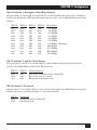
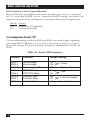
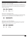
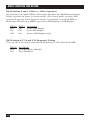
This chapter describes the locations and posssible settings of the MultiFunction Line Driver’s DIP configuration switches, and provides detailed
instructions for setting them. Once you’ve configured the Multi-Function
Line Driver, it is designed to operate reliably and transparently, without
needing to be frequently reconfigured. Just set it and forget it!
3.1 Where the Switches Are
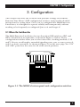
The Multi-Function Line Driver has two 8-position DIP switches—SW1 and
SW2—mounted on its underside, as shown in Figure 3-1 below. These
configuration switches allow you to select data rates, clocking methods, V.52
and V.54 tests, word lengths, extended signaling rates, sync or async protocol,
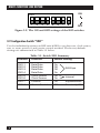
and 2- or 4-wire operation. As shown in Figure 3-2 on the next page, the “ON”
and “OFF” points are the same for all of the switch positions.
1 2 3 4 5 6 7 8
1 2 3 4 5 6 7 8
OFF
OFF
SW1
SW2
Figure 3-1. The MFLD’s bottom panel and configuration switches.
5