1
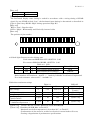
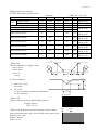
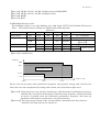
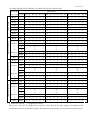
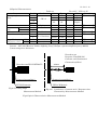
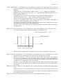
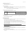
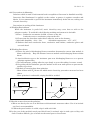
Technical Document
LCD Specification
LCD Group
LQ038Q5DR01 LCD Module
Product Specification
February 2010
QVGA module featuring very wide temperature
range and very wide temperature tolerance,
along with improved shock and vibration
resistance. Brightness is 450 nits
with contrast of 100:1.
Full Specifications Listing
RECORDS OF REVISION
LQ038Q5DR01
SPEC No.
DATE
PAGE
SUMMARY
NOTE
LD-22113
Feb.3.2010
-
-
1 st Issue
LD-22113-1
NOTICE
This publication is the proprietary of SHARP and is copyrighted, with all rights reserved. Under the
copyright laws, no part of this publication may be reproduced or transmitted in any form or by any means,
electronic or mechanical for any purpose, in whole or in part, without the express written permission of
SHARP. Express written permission is also required before any use of this publication may be made by a
third party.
The application circuit examples in this publication are provided to explain the representative applications
of SHARP's devices and are not intended to guarantee any circuit design or permit any industrial property
right or other rights to be executed. SHARP takes no responsibility for any problems related to any
industrial property right or a third party resulting from the use of SHARP's devices, except for those
resulting directly from device manufacturing processes.
In the absence of confirmation by device specification sheets, SHARP takes no responsibility for any defects
that occur in equipment using any of SHARP's devices, shown in catalogs, data books, etc. Contact SHARP
in order to obtain the latest device specification sheets before using any SHARP's device.
SHARP reserves the right to make changes in the specifications, characteristics, data, materials, structures
and other contents described herein at any time without notice in order to improve design or reliability.
Contact SHARP in order to obtain the latest specification sheets before using any SHARP's device.
Manufacturing locations are also subject to change without notice.
Observe the following points when using any device in this publication. SHARP takes no responsibility for
damage caused by improper use of the devices.
The devices in this publication are designed for use in general electronic equipment designs, such as:
・Personal computers ・Office automation
・Telecommunication equipment
・Test and measurement equipment ・Industrial control ・Personal Digital Assistant
・Audio visual and multimedia equipment ・Consumer electronics
The appropriate design measures should be taken to ensure reliability and safety when SHARP's devices
are used for equipment such as:
・Transportation control and safety equipment(i.e. aircraft, trains, automobiles, etc.)
・Traffic signals ・Gas leakage sensor breakers
・Alarm equipment
・Various safety devices etc.
SHARP's devices shall not be used for equipment that requires extremely high level of reliability, such as:
・Military and space applications
・Nuclear power control equipment
・Medical equipment for life support
Cold cathode fluorcent lamp in devices contains a small amount of mercury.
Please follow local ordinances or regulations for disposal.
Contact a SHARP representative, in advance, when intending to use SHARP's devices for any "specific"
applications other than those recommended by SHARP.
Contact and consult with a SHARP representative if there are any questions about the contents of this
publication.
LD-22113-2
(1) Application
This specification literature applies to color TFT-LCD module ,LQ038Q5DR01.
(2) Summary And Features
This module is a color active matrix LCD module incorporating amorphous silicon TFT
(Thin
Film Transistor).
It is composed of a color TFT-LCD panel, driver ICs, control-PWB, FPC, frame, front shielding case,
back-light unit.
Graphics and texts can be displayed on a 320×3×240 dots panel with 262,144 colors by supplying.
DC/AC inverter isn’t composed.
The 3.8 screen produces a high resolution image that is composed of 76,800 pixel elements in a stripe
arrangement.
Wide viewing angle technology is employed. (The most suitable viewing angle is in the
6 o'clock
direction.)
By adopting an active matrix drive, a picture with high contrast is realized.
Through the use of TN-normally white mode, an image with highly natural color image is realized.
An inverted video display in the vertical and horizontal directions is possible.
This module is adapted to RoHS compliance.
(3)Mechanical Specifications
Parameter
Display format
Active area
Screen size (Diagonal)
Dot pitch
Pixel configuration
Outline dimension
Mass
【Note 3-1】
Typical values are given.
table 3-1
Specifications
76,800
320(W) × RGB × 240(H)
78.72(W)× 53.64(H)
9.6 [3.8”]
0.082(W)× 0.2235(H)
R,G,B Stripe configuration
117.6(W)×69.45(H)×13.45(D)
Max.135
Units
pixels
dots
mm
cm
mm
mm
g
Remarks
【Note3-1】
For detailed measurements and tolerances, please refer to Fig. 1.
LD-22113-3
(4) Input Terminal
4-1) TFT-LCD Panel Driving Part
Used connector: KX14-40K5D-VIE (JAE Co. , Ltd)
Fit connector
Pin No.
1
2
3
4
5
6
7
8
9
10
11
12
13
14
15
16
17
18
19
20
21
22
23
24
25
26
27
28
29
30
31
32
33
34
35
36
37
38
39
40
Symbol
GND
VCC
Hsync
G3
T0
G4
T1
G5
HVR
GND
GND
B0
CLK
B1
GND
B2
R0
GND
R1
B3
R2
B4
GND
B5
R3
GND
R4
Vsync
R5
TEST
GND
TEST
G0
TEST
G1
TEST
G2
ENAB
VCC
GND
: KX15-40KLDLE(JAE Co. , Ltd)
Table 4-1 CN1
Description
ground
Power supply voltage
Horizontal synchronous signal
GREEN data signal
thermistor output1
GREEN data signal
thermistor output2
GREEN data signal(MSB)
Selection for horizontal and vertical scanning direction
ground
ground
BLUE data signal(LSB)
Clock signal for sampling each data signal
BLUE data signal
ground
BLUE data signal
RED data signal(LSB)
ground
RED data signal
BLUE data signal
RED data signal
BLUE data signal
ground
BLUE data signal(MSB)
RED data signal
ground
RED data signal
Vertical synchronous signal
RED data signal(MSB)
Open use only
Ground
Open use only
GREEN data signal(LSB)
Open use only
GREEN data signal
Open use only
GREEN data signal
Signal to settle the horizontal display position
Power supply voltage
ground
Remarks
【Note4-1】
【Note4-3】
【Note4-1】
【Note4-2】
LD-22113-4
【Note 4-1】
Hsync
positive
Vsync
positive
【Note 4-2】
The horizontal display start timing is settled in accordance with a rising timing of ENAB
signal. In case ENAB is fixed “Low”, the horizontal start timing is determined as described in
Fig3-A. (Don’t keep ENAB “High” during operation.(Fig3-B).)
【Note 4-3】
HVR = "Low" : Regular video
HVR = "High" : Horizontally and Vertically inverted video
【Note 4-4】
The position of pin number
40
38
36
34
32
30
28
26
24
22
20
18
16
14
12
10
8
6
4
2
39
37
35
33
31
29
27
25
23
21
19
17
15
13
11
9
7
5
3
1
4-2) Back-light fluorescent tube driving part
Used connector:BHR-02(8.0)VS-1N(JST Co. ,Ltd)
Fit connctor:SM02(8.0)B-BHS-1N(JST Co. ,Ltd)
Table 4-2 CN2
No.
Symbol i/o
Function
Color of FL cable
1
VL1
I
input terminal (High Voltage)
RED
2
VL2
I
input terminal (Low Voltage)
WHITE
Caution:Please use this thermistor in order to check the lamp temperature.
Model number of Thermistor:203GT−1 (made by Ishizuka electoronics Corporation)
Zero load resistance value at 25℃:20.0kΩ±3%
(5)Absolute maximum ratings
Parameter
Input voltage
Symbol
Table 5-1
Min.
Max.
Unit
VI
−0.3
VCC+0.3
V
GND=0V
Note
【Note 5-1】
Ta=25℃
Ta=25℃
【Note 5-2】
V
+3.3V power supply
VCC
0
5.5
Tstg
−40
℃
Storage temperature
+95
Operating temperature
Topr1
−30
℃
【Note 5-2】
+85
(panel surface)
Operating temperature
Topr2
−30
℃
【Note 5-2】
+60
( Ambient temperature )
【Note 5-1】 CK,R0∼R5,G0∼G5,B0∼B5,Hsync,Vsync,ENAB,HVR
【Note 5-2】 Humidity:95%RH Max. at Ta≦60℃
Maximum wet-bulb temperature is less than 58℃. at Ta>60℃.
Condensation of dew must be avoided as electrical current leaks will occur,
Causing a degradation of performance specifications.
LD-22113-5
(6)Electrical characteristics
6-1)TFT-LCD panel driving section
Parameter
Supply voltage
+3.3V
Current dissipation
Permissive input ripple
Input Low voltage
Input High voltage
Table 6-1
Symbol
Min.
Vcc
+2.9
−
I cc
−
VRF
−
VIL
VIH
0.7VCC
GND=0V,Ta=25℃
Max.
Unit
Remarks
+3.7
V 【Note 6-1】
180
mA 【Note 6-2,3】
100
mVpp
0.3VCC
V
【Note 6-4】
−
V
VI=0V
1.0
µA
【Note 6-5】
VI=VCC
75
µA
【Note 6-5】
VI=0V
75
µA
【Note 6-6】
VI=VCC
1.0
µA
【Note 6-6】
VI=0V
150
µA
【Note 6-7】
VI=VCC
2.0
µA
【Note 6-7】
Typ.
+3.3
140
−
−
−
Input current (Low)
IIL
−
−
Input current (High)
IIH
3.0
−
Input current (Low)
IIL
3.0
−
Input current (High)
IIH
−
−
Input current (Low)
IIL
6.0
−
Input current (High)
IIH
−
−
Vcc
2.8V
2.8V
data
data
0.3V 0.3V
t3
t4
t2
Vcc
Vcc-dip conditions
2)
2.8V≦Vcc<2.9V
td≦10ms
Vcc<2.8V
Vcc-dip conditions should also follow the
on-off conditions.
V
8
.
2
1)
td
Black(GS0)
【Note 6-2】
Typical current situation: Black (GS0) pattern
Timing: Typical
VCC= +3.3 V
【Note 6-3】Maximum current situation: Vertical stripe
pattern alternating 21 gray scale (GS21) with 42 gray scale
(GS42) every 1 dot.
Timing; Typical
VCC= +3.3 V
t1
GS21
GS42
V
9
.
2
【Note 6-1】
On-off conditions for supply voltage
0<t1≦10ms
0<t2≦10ms
0<t3≦1s
t4≧1s
LD-22113-6
【Note 6-4】CK,R0∼R5,G0∼G5,B0∼B5,Hsync,Vsync,ENAB,HVR
【Note 6-5】CK,R0∼R5,G0∼G5,B0∼B5,Hsync,Vsync
【Note 6-6】ENAB
【Note 6-7】HVR
6-2)Backlight driving section
The backlight system is an edge-lighting type with single CCFT (Cold Cathode Fluorescent
Tube). The characteristics of Lamp are shown in the following table.
Table 6-2
Parameter
Symbol
Min.
Typ.
Max.
Unit
Remarks
IL=5.5mArms
lamp voltage
VL7
470
530
590
Vrms
lamp current
IL
5.0
5.5
6.0
mArms
ordinary state
PWM dimming state
−
−
ILB
9.0
mArms
【Note 6-8】
−
【Note 6-9】
lamp frequency
fL
30
60
kHz
−
−
Ta=+25℃
kick-off voltage
1650
Vrms
【Note 6-10】
VS
−
−
Ta=−30℃
1700
Vrms
Inverter:HIU-288 [Harison Toshiba Lighting Corp.] (Output capasitor:22pF,frequency:49kHz)
【Note 6-8】available area
Dimming
100%
80%
Available area
9.0%
3.5%
-30℃
25℃
50℃
Temperature
Please turn on the lamp with symmetrical (negative and positive) voltage and current wave
form. Don’t use the unsymmetrical voltage and current wave which have spike wave.
【Note 6-9】Lamp frequency may produce interference with horizontal synchronous frequency,
and this may cause beat on the display. Therefore lamp frequency shall be detached
as much as possible from the horizontal synchronous frequency and from the
harmonics of horizontal synchronous to avoid interference.
【Note 6-10】The open output voltage of the inverter shall be maintained for more than 1s;
otherwise the lamp may not be turned on.
LD-22113-7
7) Timing Characteristics of input signals
Timing diagrams of input signal are shown in Fig.3-A, Fig.3-B.
7-1) Timing characteristics
Table 7-1
Parameter
Symbol
MIN
TYP
MAX
Unit
Remarks
Clock
frequency
1/Tc
4.5
6.3
6.8
MHz
High time
Tch
50
ns
−
−
Low time
Tcl
50
ns
−
−
Data
Setup time
Tds
50
ns
−
−
Hold time
Tdh
50
ns
−
−
Hsync-Clock phase difference
THc
50
120
ns
−
Hsync-Vsync phase difference
TVh
0
TH-10
µs
−
Note) In case of lower frequency, the deterioration of display quality, flicker etc., may be
occurred.
7-2) Horizontal display position
①In case ENAB is active
The horizontal display position is determined by ENAB signal and the input data
corresponding to the rising edge of ENAB signal is displayed at the left end of the active area.
(shown in Fig.3-A.)
Parameter
symbol
Min.
Typ.
Max.
Unit
Remark
Horizontal
50
63.5
80
µs
Cycle
TH
sync. signal
THe+308
400
440
clock
Pulse width
THp
4
12
30
clock
−
Tc−10
Enable signal
Setup time
Tes
50
ns
Pulse width
Tep
320
clock
Hsync-Enable signal phase
−
THe
14
72
clock
difference
Horizontal display period
THd
320
320
320
clock
②In Case ENAB is “Low” . (shown in Fig.3-B)
Parameter
symbol
Min.
Horizontal
56
Cycle
TH
sync. signal
380
Pulse width
THp
4
Hsync-data signal phase
THe
72
difference
Horizontal display period
THd
320
Typ.
63.5
400
12
Max.
80
440
30
Unit
µs
clock
clock
72
72
clock
320
320
clock
Max.
330
−
6
240
Unit
line
line
line
line
7-3) Vertical Display Position
Parameter
Symbol
Min.
Typ.
Vertical sync.
Cycle
TV
246
263
signal
−
Pulse width
TVp
1
Vertical display start position
TVs
6
6
Vertical display period
TVd
240
240
ENAB signal has no relation to the vertical display position.
Remark
Remarks
LD-22113-8
7-4) Input Data Signals And Display Position on The Screen
UP
D1,DH1
D2,DH1
D1,DH2
D2,DH2
D3,DH1
D320,DH1
D1,DH3
R
G
B
D1,DH240
D320,DH240
Display position of input data (H,V)
LD-22113-9
(8) Input Signals, Basic Display Color And Gray Scale of Each Color
Data signal
Colors &
Gray scale Gray Scale R0
R1
R2
R3
R4
R5
G0
G1
G2
G3
G4
G5
B0
B1
B2
B3
B4 B5
Basic color
Gray Scale of red
Gray Scale of green
Gray Scale of blue
Black
−
0
0
0
0
0
0
0
0
0
0
0
0
0
0
0
0
0
0
Blue
−
0
0
0
0
0
0
0
0
0
0
0
0
1
1
1
1
1
1
Green
−
0
0
0
0
0
0
1
1
1
1
1
1
0
0
0
0
0
0
Cyan
−
0
0
0
0
0
0
1
1
1
1
1
1
1
1
1
1
1
1
Red
−
1
1
1
1
1
1
0
0
0
0
0
0
0
0
0
0
0
0
Magenta
−
1
1
1
1
1
1
0
0
0
0
0
0
1
1
1
1
1
1
Yellow
−
1
1
1
1
1
1
1
1
1
1
1
1
0
0
0
0
0
0
White
−
1
1
1
1
1
1
1
1
1
1
1
1
1
1
1
1
1
1
Black
GS0
0
0
0
0
0
0
0
0
0
0
0
0
0
0
0
0
0
0
×
GS1
1
0
0
0
0
0
0
0
0
0
0
0
0
0
0
0
0
0
Darker
GS2
0
1
0
0
0
0
0
0
0
0
0
0
0
0
0
0
0
0
×
È
È
È
È
Ø
È
È
È
È
Brighter
GS61
1
0
1
1
1
1
0
0
0
0
0
0
0
0
0
0
0
0
Ø
GS62
0
1
1
1
1
1
0
0
0
0
0
0
0
0
0
0
0
0
Red
GS63
1
1
1
1
1
1
0
0
0
0
0
0
0
0
0
0
0
0
Black
GS0
0
0
0
0
0
0
0
0
0
0
0
0
0
0
0
0
0
0
×
GS1
0
0
0
0
0
0
1
0
0
0
0
0
0
0
0
0
0
0
Darker
GS2
0
0
0
0
0
0
0
1
0
0
0
0
0
0
0
0
0
0
×
È
È
È
È
Ø
È
È
È
È
Brighter
GS61
0
0
0
0
0
0
1
0
1
1
1
1
0
0
0
0
0
0
Ø
GS62
0
0
0
0
0
0
0
1
1
1
1
1
0
0
0
0
0
0
Green
GS63
0
0
0
0
0
0
1
1
1
1
1
1
0
0
0
0
0
0
Black
GS0
0
0
0
0
0
0
0
0
0
0
0
0
0
0
0
0
0
0
×
GS1
0
0
0
0
0
0
0
0
0
0
0
0
1
0
0
0
0
0
Darker
GS2
0
0
0
0
0
0
0
0
0
0
0
0
0
1
0
0
0
0
×
È
È
È
È
Ø
È
È
È
È
Brighter
GS61
0
0
0
0
0
0
0
0
0
0
0
0
1
0
1
1
1
1
Ø
GS62
0
0
0
0
0
0
0
0
0
0
0
0
0
1
1
1
1
1
Blue
GS63
0
0
0
0
0
0
0
0
0
0
0
0
1
1
1
1
1
1
0 :Low level voltage
1 :High level voltage
Each basic color can be displayed in 64 gray scales from 6 bit data signals. According to the
combination of total 18 bit data signals, the 262,144-color display can be achieved on the screen.
LD-22113-10
(9)Optical Characteristics
Table 9-1
Ta=+25℃, VCC=+3.3V
Symbol
Condition
Min.
Typ.
Max.
Unit
Remarks
θ6
−
60
65
degree 【Note 9-1,4】
θ12
−
35
40
degree
CR≧5
θ3
−
60
65
degree
θ9
−
−
【Note 9-2,4】
Contrast ratio
CRmax
Optimum
100
τr
θ=0°
−
【Note 9-3,4】
Response
Rise
30
60
ms
τd
−
time
Fall
50
100
ms
−
【Note 9-5】
Luminance
Y
IL=5.5mArms
350
450
cd/m2
【Note 9-5】
White chromaticity
x
0.263
0.313
0.363
IL=5.5mArms
y
0.279
0.329
0.379
+25℃
−
−
−
【Note 9-6】
Lamp life time
continuation
20,000
hour
−
−
−
【Note 9-7】
(Reference value) −30℃
intermission
2,000
times
DC/AC inverter for external connection shown in following.
Inverter:HIU-288 [Harison Tosihba Lighting Corp.] (Output capasitor:22pF,frequency:49kHz)
※measuring after 30minutes
Parameter
Viewing angle
range
Photodetector
Response Time(BM-5A)
Contrast ratio/Luminance/
Chromaticity(SR-3)
Photodetector(EZ-CONTRAST)
400mm
Field=1°
Center of screen(θ=0°)
Center of screen(θ=0°)
TFT-LCD-Module
TFT-LCD-Module
Fig.9-1) Viewing Angle
Measurement Method
Fig.9-2)
Luminance / Contrast ratio / Response time
Chromaticity Measurement Method
Fig.9 Optical Characteristics Measurement Method
LD-22113-11
【Note 9-1】 Viewing angle range is defined as follows.
Normal line
θ92
θ
θθ6
11
θ 12
θθ3
2
6 o’clock direction
Definition for Viewing Angle
【Note 9-2】Contrast ratio is defined as follows:
Photo detector output with LCD being "white"
Contrast ratio(CR)=
Photo detector output with LCD being "black"
【Note 9-3】Response time is obtained by measuring the transition time of photo detector
output, when input signals are applied so as to make the area "black" to and
from "white".
White
Black
White
100%
90%
t
u
p
t
u
o
r
e
t
c
e
t
e
d
o
t
o
h
P
)
t
i
n
u
y
r
a
r
t
i
b
r
a
(
10%
0%
τr
τd
Time
【Note 9-4】Measured on the center area of the panel at a viewing cone 2°(= Filed) by
TOPCON luminance meter BM-5A, SR-3 or ELDIM luminance meter EZ Contrast.
(After 30 minutes operation)
DC/AC inverter driving frequency:( 49 kHz)
【Note 9-5】Measured on the center area of the panel at a viewing cone 1°(= Filed) by
TOPCON luminance meter BM-5A, SR-3.(After 30 minutes operation)
DC/AC inverter driving frequency:( 49 kHz)
LD-22113-12
【Note 9-6】Lamp is consumables. In the following condition, the lamp life time is 20,000
hours as the reference value and it is not guaranteed in this specification sheet by
SHARP.
Lamp life time is defined that it applied either ① or ② under this condition.
※Continuous turning on at Ta = 25 oC, IL = 5.5mA rms and PWM dimming 80%~5%
(IL= 9.0mArms Ta= 25℃).
①Brightness becomes 50% of the original value under standard condition.
②Kick-off voltage at Ta = −30 oC exceeds maximum value (1700Vrms).
Lamp life time shortens according to the state of mounting and use.
In case of operating under lower temp environment, the lamp exhaustion is
accelerated and the brightness becomes lower.
Continuous operating for around 1 month under lower temp condition may reduce
the brightness to half of the original brightness.
In case of such usage under lower temp environment, periodical lamp exchange is
recommended.
【Note 9-7】The intermittent cycles is defined as a time when brightness not to become under
50% of the original value under the condition of following cycle.
Ambient temperature:−30℃
HIGH(9mArms)
OFF
5min 5min 5min 5min
Don’t use the unsymmetrical voltage and current wave which have spike wave.
【Note 9-8】The performance of the backlight, for example life time or brightness, is much
influenced by the characteristics of the DC-AC inverter for the lamp.
When you design or order the inverter, please make sure that a poor lighting
caused by the mismatch of the backlight and the inverter (miss-lighting,flicker,
etc.) never occur. when you confirm it, the module should be operated in the same
condition as it is installed in your instrument.
Be sure to use a back light power supply with the safety protection circuit such as
the detection circuit for the excess voltage, excess current and or electric discharge
waveform.
【Note 9-9】Please make it to the structure not touching directly insulating the high voltage
part.
Please stop the circuit by the protection element such as fuses for generation of
heat and the ignition prevention, and use a flame resisting and high material for
the substrate and the resin material.
【Note 9-10】Under the environment of 10lx or less, miss-lighting delay may occur.
LD-22113-13
(10) Mechanical Characteristics
10-1) External Appearance
Do not exist extreme defects. (See Fig. 1)
10-2) Panel Toughness
The panel shall not be broken ,when 19N is pressed on the center of the panel by a
smooth sphere having 15 mm diameter.
Caution:In spite of very soft toughness, if, in the long-term, add pressure on the active
area, it is possible to occur the functional damage.
10-3) Input / Output Connector Performance
I/O connector of backlight driving circuit 【JST】
Lump connector
Symbol
Used Connector
Corresponding Connector
CN
BHR-02(8.0)VS-1N
SM02(8.0)B-BHS-1N(assembled on PWB)
A, B
SM02(8.0)B-BHS-TB(assembled on PWB)
BHMR-03V (interconnecter)
(11) Display Quality
The display quality of the color TFT-LCD module shall be in compliance with the Incoming
Inspection Standards for TFT-LCD.
(12) Handling Instructions
12-1) Mounting of Module
① The TFT-LCD module is designed to be mounted on equipment using the mounting tabs in
the four corners of the module at the rear side.
Connect GND to these mounting tabs to stabilize against EMI and external noise.
On mounting the module, as the M2.6 tapping screw fastening torque is 0.3 through
0.5N・m is recommended, be sure to fix the module on the same plane, taking care not to
wrap or twist the module.
Don't reach the pressure of touch-switches of the set side to a module directly, because
images may be disturbed.
② Please power off the module when you connect the input/output connector.
③ Please connect the metallic shielding cases of the module and the ground pattern of the
inverter circuit surely. If that connection is not perfect, there may be a possibility that
the following problems happen.
a). The noise from the backlight unit will increase.
b). The output from inverter circuit will be unstable. Then, there may be a possibility that
some problems happen.
c). In some cases, a part of module will heat.
d).Please taking care to pull back-light’s cable, when you connect the back-light cable’s
connector.
LD-22113-14
12-2) Precautions in Mounting
Polarizer which is made of soft material and susceptible to flaw must be handled carefully.
Protective film (Laminator) is applied on the surface to protect it against scratches and
dirties. It is recommended to peel off the laminator immediately before the use, taking care
of static electricity.
Precautions in peeling off the laminator
A) Working Environment
When the laminator is peeled off, static electricity may cause dust to stick to the
polarizer surface. To avoid this, the following working environment is desirable.
a) Floor:Conductive treatment of 1MΩ or more on the tile
(conductive mat or conductive paint on the tile)
b) Clean room free form dust and with an adhesive mat on the doorway.
c) Advisable humidity:50%∼70%
Advisable temperature:15℃∼27℃
d) Workers shall wear conductive shoes, conductive work clothes, conductive gloves and
an earth band.
B) Working Procedures
a) Direct the wind of discharging blower somewhat downward to ensure that module is
blown sufficiently. Keep the distance between module and discharging blower within
20 cm.
b) Attach adhesive tape to the laminator part near discharging blower so as to protect
polarizer against flaw.
c) Peel off laminator, pulling adhesive tape slowly to your side taking 5 or more second.
d) On peeling off the laminator, pass the module to the next work process to prevent the
module to get dust.
e) Method of removing dust from polarizer
・ Blow off dust with N2 blower for which static electricity preventive measure has been
taken.
・ Since polarizer is vulnerable, wiping should be avoided.
Direction of wind of blower
discharging blower
less than 20cm
module
Adhesive tape
backlight cable
C) How the remove dust on the polarizer
a) Blow out dust by the use of an N2 blower with antistatic measures taken. Use of an ionized
air Gun is recommendable.
b) When the panel surface is soiled, wipe it with soft cloth.
D) In the case of the module’s metal part (shield case) is stained, wipe it with a piece of dry, soft
cloth. If rather difficult, give a breath on the metal part to clean better.
LD-22113-15
E) If water dropped, etc. remains stuck on the polarizer for a long time, it is apt to get
discolored or cause stains. Wipe it immediately.
F) As a glass substrate is used for the TFT-LCD panel, if it is dropped on the floor or hit by
something hard, it may be broken or chipped off.
G) Since CMOS LSI is used in this module, take care of static electricity and take the human
earth into consideration when handling.
12-3) Precautions in Adjusting module
Adjusting volumes on the rear face of the module have been set optimally before shipment.
Therefore, do not change any adjusted values. If adjusted values are changed, the
specifications described here may not be satisfied.
12-4) Caution of Product Design
The LCD module shall be protected against water salt-water by the waterproof cover.
Please take measures to interferential radiation from module, to do not interfere
surrounding appliances. The polarizer surface on the panel is treated with Anti-Glare for low
reflection. In case of attaching protective board over the LCD, be careful about the optical
interface fringe etc. which degrades display quality.
12-5) Others
A) Do not expose the LCD panel to direct sunlight. Lightproof shade etc. should be attached when
LCD panel is used under such environment. The panel characteristic might be deteriorated and
the display fineness decrease when strong light is irradiated to the liquid crystal panel.
B) There are high voltage portions on the backlight and very dangerous. Careless touch may lead to
electrical shock. When exchange lamps or service, turn off the power without tail.
C) Cold cathode fluorescent lamp in LCD panel contains a small amount of mercury, please follow
local ordinances or regulations for disposal.
D) Be careful of a back light lead not to pull by force at the time of the wiring to an inverter, or line
processing.
E) The lamp used for this product is very sensitive to the temperature. Luminance decreases rapidly
when it is used for a long time or repeatedly under the environment of the low temperature or the
module is being cooled. Please avoid the continuous or repeating use of it under such an
environment. It may decrease up to 50% of the initial luminance in about one month under the
low temperature environment. Please consult our company when it is used under the
environment like the above mentioned.
F) If stored at temperatures below the rated values, the inner liquid crystal may freeze, causing
cell destruction. At temperatures exceeding the rated values for storage, the liquid crystal
may become isotropic liquid, making it no longer possible to come back to its original state
in some cases.
G) If the LCD is broken, do not drink liquid crystal in the mouth. If the liquid crystal adheres
to a hand or foot or to clothes, immediately cleanse it with soap.
H) If a water drop or dust adheres to the polarizer, it is apt to cause deterioration. Wipe it
immediately.
I) Be sure to observe other caution items for ordinary electronic parts and components.
J) When handling LCD modules and assembling them into cabinets, that long-terms storage in
the environment of oxidization or deoxidization gas and the use of such materials as reagent,
LD-22113-16
solvent, adhesive, resin, etc. which generate these gasses, causes corrosion and discoloration
of the modules. Therefore, please avoid these use. Epoxy resin (amino series curing agent),
silicone adhesive material (dealcoholization series and oxime series), Tray forming agent
(azo compound) etc, in the cabinet or the packing materials may induce abnormal display
with polarizer film deterioration. Be sure to confirm the component of them.
K) In case of attaching protective board (or tatch-panel, etc) over the LCD, be careful about the
optical interface fringe etc. which degrades display quality.
L) The LED used for thes product is very sensitive to the temperature. Luminance decreases
rapidly when it issued for a long time under the environment of the high temperature.
Please consult our company when it is used under the environment like the above
mentioned.
M) Please be careful that you don’t keep the screen displayed fixed pattern image for a long
time, since retention may occur.
N) Disassembling the module can cause permanent damage and you should be strictly avoided.
Please don’t remove the fixed tape, insulating tape etc that was pasted on the original
module.(Except for protection film of the panel.)
O) If a minute particle enters in the module and adheres to an optical material, it may cause
display non-uniformity issue, etc. Therefore, fine-pitch filters have to be installed to cooling
and inhalation hole if you intend to install a fan.
P) VCOM value have been set optimally before shipment, so do not change any adjusted value.
If adjusted value is changed, the specification may not be satisfied.
Q) Be sure to use a power supply with the safety protection circuit such as the fuse for the
excess voltage, excess current and or electric discharge waveform.
R) If you pressed down a liquid crystal display screen with your finger and so on, the alignment
disorder of liquid crystal will occur. And then It will become display fault. Therefore, be
careful not to touch the screen directly, and to consider not stressing to it.
S) If any problem arises regarding the items mentioned in this specification sheet or otherwise,
it should be discussed and settled mutually in a good faith for remedy and/or improvement.
(13) Packing Form (shown in Fig.4.)
Piling number of cartons
:MAX 10
Package quantity in one carton
:50 pcs
Carton size
:503 (W)×166 (H)×338 (D) mm
Total mass of one carton filled with full modules
:MAX. 7.5kg
Conditions for storage.
Environment
①Temperature
:0∼40℃
②Humidity
:60%RH or less (at 40℃)
No dew condensation at low temperature and high humidity.
③Atmosphere
:Harmful gas, such as acid or alkali which bites electronic
components and/or wires, must not be detected.
④Direct sunshine
:Please keep it in the state of wrapping or the darkroom so that
direct sunshine should not strike directly into the product.
⑤Asking for be dewy prevention
・Please do not put directly on the floor, and keep the wrapping box on the palette or the
stand to avoid the be dewy. Moreover, please arrange it in a constant direction correctly to
improve ventilation under the palette.
・Please separate from the wall in the storage warehouse and keep it.
LD-22113-17
・Please note that ventilation is improved and consider the installation such as ventilators in
the warehouse.
・ Please manage so that there is no rapid temperature change more than natural
environment.
⑥Period
:about 3 months
⑦Opening of the package:In order to prevent the LCD module from breakdown electrostatic
charges, please control the room humidity over 50%RH and open
the package taking sufficient countermeasures against
electrostatic charges, such as earth, etc.
(14) Reliability Test
Reliability test conditions for the TFT-LCD module are shown in Table 14.
(15) Indication of Lot Number
①Attached location of the label:See Fig. 1
②Indicated contents of the label
LQ038Q5DR01 M ○○○○○○○○
model No.
lot No.
Contents of lot No.
the 1st figure ‥ production year ( ex. 2010 : 0 )
the 2nd figure ‥ production month 1,2,3,‥‥‥,9,X,Y,Z
the 3rd∼8th figure ‥ serial No.
000001∼
the 9th figure ‥ revision marks A,B,C‥
LD-22113-18
Reliability Test Conditions for TFT-LCD Module
Table 14
Remark) Temperature condition is based on operating temperature conditions on (5)-Table 5-1.
No.
Test items
Test Conditions
240h
1 High temperature storage test
Ta= +95℃
240h
2 Low temperature storage test
Ta= −40℃
High
temperature
and
240h
3
Tp= +60℃ , 95%RH
high humidity operating test
240h
4 High temperature operating test
Tp= +85℃
240h
5 Low temperature operating test
Ta= −30℃
6 Electro static discharge test
±200V・200pF(0Ω)
1 time for each terminals
2
7 Shock test
980m/s ・6ms, ±X;±Y;±Z
3 times for each direction
(JIS C0041, A-7 Condition C)
8 Vibration test
Frequency range:8∼33.3Hz
Stroke:1.3mm
Sweep:33.3Hz∼400Hz
Acceleration:28.4m/s2
Cycle:15 minutes
X,Z 2 hours for each directions, 4 hours for Y direction
(total 8 hours) 【caution】(JIS D1601)
9 Heat shock test
Ta= −40℃∼+95℃ / 200 cycles
(0.5h) (0.5h)
【Note】Ta= Ambient temperature, Tp= Panel temperature
【Check items】In the standard condition, there shall be no practical problems that may affect
the display function.
【caution】X,Y,Z directions are shown as follows:
Z
X
Y
LCY00044−17
LD-22113-19
LCY00044−18
LD-22113-20
Fig.2. Structure of the module
TH:(THe+308)CK∼440CK
C
C
V
7
.
0
C
C
V
7
.
0
C
C
V
3
.
0
C
C
V
3
.
0
Horizontal
sync. signal
THp
(Hsync)
TH T
0.5VCC
Number of clock
Data signal
(R0∼R5,G0∼G5,
B0∼B5)
0.5VCC
C
C
V
3
.
0
C
C
V
3
.
0
C
C
V
3
.
0
Clock signal
(CK)
Tc
Tch Tcl
THc
Horizontal invalid data period
D1
D2
THe
Tds Tdh
D3
Number of H-data
D319
D320
Horizontal invalid data period
THd
C
C
V
7
.
0
C
C
V
3
.
0
Tes
Data enable signal
(ENAB)
Tep
TV
C
C
V
7
.
0
TVp
C
C
V
7
.
0
Horizontal
sync. signal
(Hsync)
C
C
V
3
.
0
(Vsync)
C
C
V
7
.
0
Vertical
sync. signal
TVs
Data signal
(R0∼R5,G0∼G5,
B0∼B5)
TVd
Vertical invalid data
DH1
DH2
DH3
Number of line
DH239
DH240
Vertical invalid data period
Number of V-data line
LD-22113-21
Fig3-A) Input Signal Waveform
TH:380CK∼440CK
C
C
V
7
.
0
C
C
V
7
.
0
C
C
V
3
.
0
C
C
V
3
.
0
Horizontal
sync. signal
THp
(Hsync)
TH T
0.5VCC
Tds Tdh
Data signal
(R0∼R5,G0∼G5,
B0∼B5)
0.5VCC
C
C
V
3
.
0
K
C
2
7
C
C
V
3
.
0
C
C
V
3
.
0
Clock signal
(CK)
Tc
Tch Tcl
THc
Horizontal invalid data period
D1
D2
Number of H-data
Number of clock
D3
D319
D320
Horizontal invalid data period
THd
Data enable signal
(ENAB)
TV
C
C
V
7
.
0
TVp
C
C
V
7
.
0
Horizontal
sync. signal
(Hsync)
C
C
V
3
.
0
(Vsync)
C
C
V
7
.
0
Vertical
sync. signal
TVs
Data signal
(R0∼R5,G0∼G5,
B0∼B5)
Vertical invalid data
TVd
DH1
DH2
DH3
Number of line
DH239
DH240
Vertical invalid data period
Number of V-data line
LD-22113-22
Fig3-B) Input Signal Waveform
LD-22113-23
LCY00044-21
Fig.4.Packing form
Technical Document
LCD Specification
LCD Group
NORTH AMERICA
Sharp Microelectronics of the Americas
5700 NW Pacific Rim Blvd.
Camas, WA 98607, U.S.A.
Phone: (1) 360-834-2500
Fax: (1) 360-834-8903
www.sharpsma.com
TAIWAN
Sharp Electronic Components
(Taiwan) Corporation
8F-A, No. 16, Sec. 4, Nanking E. Rd.
Taipei, Taiwan, Republic of China
Phone: (886) 2-2577-7341
Fax: (886) 2-2577-7326/2-2577-7328
CHINA
Sharp Microelectronics of China
(Shanghai) Co., Ltd.
28 Xin Jin Qiao Road King Tower 16F
Pudong Shanghai, 201206 P.R. China
Phone: (86) 21-5854-7710/21-5834-6056
Fax: (86) 21-5854-4340/21-5834-6057
Head Office:
No. 360, Bashen Road,
Xin Development Bldg. 22
Waigaoqiao Free Trade Zone Shanghai
200131 P.R. China
Email: [email protected]
EUROPE
Sharp Microelectronics Europe
Division of Sharp Electronics (Europe) GmbH
Sonninstrasse 3
20097 Hamburg, Germany
Phone: (49) 40-2376-2286
Fax: (49) 40-2376-2232
www.sharpsme.com
JAPAN
Sharp Corporation
Electronic Components & Devices
22-22 Nagaike-cho, Abeno-Ku
Osaka 545-8522, Japan
Phone: (81) 6-6621-1221
Fax: (81) 6117-725300/6117-725301
www.sharp-world.com
SINGAPORE
Sharp Electronics (Singapore) PTE., Ltd.
438A, Alexandra Road, #05-01/02
Alexandra Technopark,
Singapore 119967
Phone: (65) 271-3566
Fax: (65) 271-3855
HONG KONG
Sharp-Roxy (Hong Kong) Ltd.
Level 26, Tower 1, Kowloon Commerce Centre,
No. 51, Kwai Cheong Road, Kwai Chung,
New Territories, Hong Kong
Phone: (852) 28229311
Fax: (852) 28660779
www.sharp.com.hk
Shenzhen Representative Office:
Room 602-603, 6/F.,
International Chamber of Commerce Tower,
168 Fuhua Rd. 3, CBD,
Futian District, Shenzhen 518048,
Guangdong, P.R. China
Phone: (86) 755-88313505
Fax: (86) 755-88313515
KOREA
Sharp Electronic Components
(Korea) Corporation
RM 501 Geosung B/D, 541
Dohwa-dong, Mapo-ku
Seoul 121-701, Korea
Phone: (82) 2-711-5813 ~ 8
Fax: (82) 2-711-5819
SPECIFICATIONS ARE SUBJECT TO CHANGE WITHOUT NOTICE.
Suggested applications (if any) are for standard use; See Important Restrictions for
limitations on special applications. See Limited Warranty for SHARP’s product warranty.
The Limited Warranty is in lieu, and exclusive of, all other warranties, express or implied. ALL EXPRESS AND IMPLIED WARRANTIES, INCLUDING THE WARRANTIES OF
MERCHANTABILITY, FITNESS FOR USE AND FITNESS FOR A PARTICULAR PURPOSE,
ARE SPECIFICALLY EXCLUDED. In no event will SHARP be liable, or responsible in
any way, for any incidental or consequential economic or property damage.
LD-22113