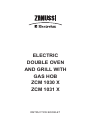
1
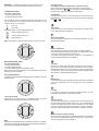
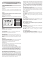
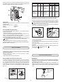
ELECTRIC
DOUBLE OVEN
AND GRILL WITH
GAS HOB
ZCM 1030 X
ZCM 1031 X
INSTRUCTION BOOKLET
For your safety
Do not use abrasive cleaners or powders that will scratch the
surface of the stainless steel and the enamel.
Do not use this cooker if it is in contact with water.
Do not operate the cooker with wet hands.
Do not let the supply cables of electrical appliances, which are
being used close to the cooker, come into contact with it's hot
surfaces.
Do not use unstable or misshapen pans as unstable pans can
cause an accident by tipping or spillage.
Warning: You must read these warnings carefully before
installing or using the appliance. If you need assistance,
contact our Customer Services Department on 08705 727727.
The product should only be used for its intended purpose which
is for the cooking of domestic foodstuffs. Under no circumstances
shouid any external covers be removed for servicing or
maintenance except by suitably qualified personnel.
Do's and Do Not's
Do make sure you understand the controls before using the
cooker.
Do check that all controls on the cooker are turned off after use.
Do always stand back when opening an oven door to allow heat
to disperse.
Do always use dry, good quality oven gloves when removing
items from the oven.
Do take care when removing items from the oven, as the contents
may be hot.
Do always keep the oven doors closed when the cooker is not
in use.
Do always place pans centrally over the hob burners and position
them so that the handles cannot accidentally be caught or knocked
or become heated by other burners.
Do keep the cooker clean, as a build up of grease or fat from
cooking can cause a fire.
Do always allow the cooker to cool before cleaning.
Do always follow the basic principles of food handling and hygiene
to prevent the possibility of bacterial growth.
Do always keep ventilation slots clear of obstructions.
Do always turn off the electricity before cleaning or replacing an
oven lamp.
Do always use a CORGI registered Service Force engineer for
servicing.
Installation
This cooker must be installed by qualified personnel, according
to the manufacturer's instructions and to the relevant British
Standards.
For appliances installed in the Republic of Ireland please refer to
NSAI-Domestic Gas Installations I.S.813 Current Editions and the
ETCI Rules for Electrical Installations.
The cooker is heavy. Take care when moving it.
Any gas installation must be carried out by a registered Corgi, or
similar, installer.
Remove all packaging before using the cooker.
Ensure that the gas and electrical supply complies with the type
stated on the rating plate, located on the inside the front appliance
drawer.
Do ensure that there is adequate ventilation in the room if the
appliance is in use for prolonged periods.
Do ensure the control knobs are in the 'OFF' position when not
in use.
Do not allow children near the cooker when in use as all surfaces
will become hot during and after cooking. They can also injure
themselves by pulling pans or pots off the hob.
Do not allow anyone to sit or stand on any part of the cooker.
Do not heat up unopened food containers as pressure can build
up causing the container to burst.
Do not store chemicals , food stuffs, pressurised containers in
or
on the cooker, or in cabinets immediately above or next to the
cooker.
Do not fill a deep fat frying pan more than1/3 full of fat, oil, or use
a lid. DO NOT LEAVE UNATTENDED WHILE COOKING.
Do not place flammable or plastic items on or near the hob
burners.
Do not use proprietary spillage collectors on the hob burners.
Do not use the cooker as a room heater.
Do not dry clothes or place other items over or near to the hob
burners or oven doors.
Do not wear garments with long flowing sleeves whilst cooking.
Do not place inflammable materials in the oven or the compartment
below the oven.
Do not allow fat or oil to build up in the oven trays, grill pan or
oven base.
Do not place cooking utensils or plates onto the oven base.
Do not grill food containing fat without using the grid.
Do not cover the grilling grid with aluminium foil.
Do not place hot enamel parts in water, leave them to cool first.
Do not allow vinegar, coffee, milk, saltwater, lemon or tomato
juice to remain in contact with enamel parts (inside the oven and
oven trays).
2
GENERAL INFORMATION
TECHNICAL AFTER SALES SERVICE
Before leaving the factory, this appliance has been tested and
set up by skilled personnel, in order to give the best performance
results. Each repair or commissioning that may be necessary
afterwards, must be carried out with a care and attention. For this
reason, we recommend that you always use our authoried Service
and always specify the nature of the problem and the model
of your appliance.
For contact details please refer to 'Service and Spare Parts'.
ENVIRONMENT PROTECTION
Packing disposal
Sort packing into different materials (cardboard, polystyrene
etc.) and dispose of them in accordance with local waste
disposal laws.
WARNING: Risk of suffocation. Keep all packaging away
from children.
This appliance complies with the following European Directives:
- 73/23/EEC regarding "Low Voltage".
- 89/336/EEC regarding "Electromagnetic Disturbances".
- 90/396/EEC regarding “Gas appliances”
- 89/109/EEC regarding "Materials in contact with food"
- Moreover the above mentioned Direstives comply with Directive
93/68/EEC regarding CE Marking.
- This household appliance has been designed for cooking and
it must therefore be used for this purpose only.
RECOMANDATIONS AND PRECAUTIONS
ATTENTION:
- Before using the appliance, do not forget to remove the plastic
films protecting some parts of the appliance (facia-panel, parts
in stainless steel, etc.)
- Do not use the appliance as a space heater.
- When the appliance is not in use, we recommend to switch off
the electricity supply to the appliance.
DEAR CUSTOMER,
• Carefully read these instructions before using the appliance and
keep them for future consultation.
• Keep potentially hazardous packaging (plastic bags, polystyrene
etc.) out of the reach of children.
IN CASE OF FIRE:
• In case of fire, close the main valve of the gas supply and
switch off the electricity supply to the appliance and never
pour water onto burning oil. Do not store flammable products or
aerosol containers near the burners, and do not spray them near
lit burners.
WARRANTY
Your new appliance is covered by a warranty.
A registration card is enclosed If it is missing, you can register
your 12 month guarantee by telephoning 08705 606 9876 or by
visiting our website at www.zanussi-electrolux.co.uk
Keep the section meant for you, and when, if necessary, show it
to the Service engineer together with the purchase receipt.
If you do not follow this procedure, you could be charged for any
service visits that may be necessary.
For full Terms and Conditions of Guarantee please see the
chapter 'Guarantee Conditions'.
FOR YOU AND YOUR CHILDRENS SAFETY
• Do not store items that are attractive to children above or near
the appliance.
• Keep children well away from the appliance: some parts of the
appliance and the pans become very hot during use, and during
the cool down period after use.
• In order to avoid any accidental tipping, pan handles should be
turned towards the back of the cooker, not out into the room or
over adjacent burners.
• When cooking, do not use clothes with large flared sleeves; in
case of accidental contact with a lit burner.
WARNING - OVEN:
When the oven or the grill are in use, accessible parts can
become very hot; it is necessary to keep children well away
from the appliance.
- Never cook food on the base of the oven.
- Keep fingers away from the area of the hinges when closing the
door as it is possible to trap them.
- Do not let children sit down on or play with the oven door. Do
not use the drop down door as a stool to reach cabinets above.
WARMING DRAWER
DO not place inflammable materials or plastic utensils in the
warming drawer (situated below the ovens).
3
DESCRIPTION OF THE APPLIANCE
A Semirapide burner
B Rapide burner
C Triple crown burner
D Hob top
E Control panel
F Door Handle
G Oven door ( main oven )
H Oven door ( second oven)
I Adjustable feet
B
C
A
D
A
F
E
B
H
F
I
G
Control panel
7 Control knob function ( second oven )
8 Control knob ( rapide burner left )
9 Control knob ( semirapide burner left )
10 Control knob ( Triple crown burner )
11 Control knob ( rapide burner right )
12 Control knob ( semirapide burner right )
1 Electronic clock
2 Oven indicator light ( main oven )
3 Oven indicator light ( function )
4 Oven indicator light ( second oven)
5 Control knob function ( main oven )
6 Thermostat knob ( main oven )
1
2
3
5
4
6
7
8
4
9
10
11
12
USE OF THE ELECTRIC OVEN
HOB USE
Before the first use of the oven
The first time the oven is used, it may give off smells, these are
caused by residues left by the production processes and is quite
normal. Ensure there is adequate ventilation in the room before
performing this action. (It is necessary to heat up the oven at
the maximum temperature for about 30-40 minutes in order
to burn off these residues).
Once this process is complete cooking can commence.
The oven is fitted with: a wire trivet for cooking food contained in
oven dishes or placed directly on the trivet itself, a drip-tray for
cooking sweets, biscuits, pizzas, etc., or for collecting juices and
fats from food cooked directly on the trivet.
Note: The tables at page 6 give the main points for cooking some
of the most common dishes. The cooking times recommended in
these tables are approximate. After a few tries, we are sure that
you will be able to adjust the times to get the results you want.
USING GAS BURNERS
The following symbols are on the control panel next to each knob:
- Black circle
gas off
- Large flame
maximum setting
- Small flame
minimum setting
The minimum setting is at the end of the anticlockwise rotation of
the knob. All operation positions must be selected between the
positions of max. and min., never select them between max. and
off.
MANUAL IGNITION (during mains power failure)
To ignite the burner, press the knob of the selected burner and
turn it anticlockwise to the minimum position then light with a
match.
AUTOMATIC ELECTRIC IGNITION (optional)
To ignite the burner, press the knob of the selected burner and
turn it anticlockwise to the minimum position. Keeping the knob
pressed in, the automatic ignition of the burner will operate.
In case of power failure, the burner can also be lit using a match.
APPLIANCES WITH THERMOCOUPLES (if fitted)
Follow the same procedure described above to ignite the burners.
In this case, once the burner is lit you have to hold the control
knob pressed in for approximately 10 seconds until the burner
flame stays on, if the flame does not stay on repeat the process.
If for any reason the burner flame goes out, the safety valve
automatically shuts off the gas supply to the burner in question.
ENERGY SAVING TIPS
• The diameter of the pan bottom should correspond to that of
the burner. The burner flame must never extend beyond the
diameter of the pan. Use flat-bottomed pans only.
• Whenever possible, keep a lid on the pan while cooking, this
will save energy.
• Cook vegetables, potatoes, etc. with as little water as possible
to reduce cooking times.
Fig.1
BURNERS
PANS
Ø min.
Ø max
RAPIDE
180 mm
220 mm
SEMIRAPIDE
120 mm
200 mm
AUXILIARY
80 mm
160 mm
TRIPLE CROWN 220 mm
260 mm
5
Recommended cooking tables
Cooking times vary according to the nature, type and quantity of the food. We recommend
monitoring your first attempts and checking the results, as similar results are obtained by cooking
the same dishes in the same conditions. The following three tables (I, II and III) provide guidelines.
6
Use of the oven
The appliance must be used with the oven door closed.
Note: ovens with separate thermostat and function selectors.
When the functions
are used, place the thermostat knob
between 180 ÷ 200°C as maximum temperature.
WARNING – Accessible parts will become hot when in use.
To avoid burns and scalds children should be kept away.
CONVECTION OVEN
The oven is fitted with:
• a lower heating element;
• an upper heating element.
ATTENTION:
The temperature shown on the control panel corresponds to the
temperature in the oven centre only when the functions selected
are
or
.
It is possible to select the desired temperature into the oven by
turning clockwise the thermostat knob and depending on the
models, one or more functions:
Oven off
Oven lamp
When you turn the control knob to this position, the light will be
on for all the following operations.
Oven light
60 ÷ max Upper + lower heating element on
Upper heating element on
Lower heating element on
Grill element on
Defrosting with fan
The air at ambient temperature is distributed inside the oven for
defrosting food faster.
Note: The appliance must be used with the oven door closed.
60
0
MA
X
170
200
0
13
90
Natural convection
Both the lower and upper heating elements operate together.
This is the traditional cooking, very good for roasting joints, ideal
for biscuits, baked apples and crisping food.
You obtain very good results when cooking on a shelf adjusting
the temperature between 50 and MAX°C.
MULTIFUNCTIONAL OVEN
The oven is fitted with:
• a lower heating element;
• an upper heating element;
• a circular heating element surrounding the fan.
N.B.: Always set the temperature on the thermostat knob before
selecting any of the functions.
Fan oven
Both the fan and the circular heating element operate together.
The hot air is adjustable between and MAX°C and is evenly
distributed inside the oven. This is ideal for cooking several types
of food (meat, fish etc) at the same time without affecting taste
and smell. It is ideal for delicate pastries.
Oven thermostat knob
To obtain an oven temperature between 50°C and MAX°C, turn the
knob clockwise.
50
0
M
Medium grill
It is ideal for grilling and gratinating small quantities of traditional
food. The thermostat knob must be placed on the maximum
position.
AX
0
10
200
Full grill
It is ideal for grilling and gratinating traditional food. Set the
thermostat control knob to the 200°C position.
150
Oven selector knob
Depending on the type of oven, it is possible to select one of the
following functions turning the selector knob clockwise.
Thermal grilling
The air which is heated by the grill element is circulated by the
fan which distributes the heat on the food. The fan assisted grill
function can replace the need to use the rotisserie. You can obtain
very good results also with large quantities of poultry, sausage,
red meat. Set the thermostat control knob to the 200°C position.
0
Air forced lower heating element
The air which is heated by the lower heating element is circulated
by the fan which distributes the heat on the food . This function
can be used between 50° and MAX°C.
Note:
All the functions mentioned above, switch the oven light on. A warning
light on the control panel will stay lit until the selected temperature is
reached; after it will light up intermittently.
7
Automatic use with cooking time and end time setting
Press the cooking time button and select the length of the cooking
time with + or - button. The “AUTO” and cooking time symbols
light up continuously. The relay switches on. By pressing the
cooking end time button the next cooking end time appears on
the display. Set the cooking end time with + button. The relay
and
the cooking time symbol switch off.
The symbol lights up again when the time of day corresponds to
the cooking start time. When the cooking time is up, the “AUTO”
symbol flashes, the sound signal rings, the cooking time symbol
and the relay switch off.
INSTRUCTIONS FOR USE OF CLOCK AND TIMER
(ACCORDING TO THE MODELS)
“LED” PROGRAMMER (Fig. 5)
Features
24 hour clock with automatic programme and minute minder.
Functions
Cooking time, cooking end time, manual position, clock,
minute minder, times to be set up to 23 hours 59 minutes.
Minute minder
Press the minute minder button and set the cooking time with
+ or - button.
The bell symbol lights up when the minute minder is operating.
When the set time is up, the audible signal rings and the bell
symbol
switches off.
Display
4-figures, 7-segments display for cooking times and time of day.
Cooking time and manual function = saucepan symbol
Automatic function = AUTO
Minutes minder = bell symbol
The symbols light up when the corresponding functions are
selected.
Audible signal
The audible signal starts at the end of a programme or of the
minute minder function and it lasts for 15 minutes.
To stop it, push any one of the function buttons.
Minute minder
A
Cooking time
Start programme and check
The programme starts 4 seconds after it has been set.
The programme can be checked at any time by pressing the
corresponding button.
Cooking end
Manual
Subtract time
Add time
Setting error
A setting error is made if the time of day on the clock falls within
the cooking start and end times.
To correct the setting error, change the cooking time or cooking
end time.
The relays switch off when a setting error is made.
Fig. 5
Setting
To set, press and release the desired function, and within 5 seconds
set the time with + and - buttons.
Cancelling a setting
To cancel a setting, press the cooking time button and then press
the - button until 00 00 appears on the display.
A set programme will automatically cancel on completion.
+ and - buttons.
The + and - buttons increase or decrease the time at a speed
depending on how long the button is pressed.
Setting the time
Press any two buttons (cooking time, end time, minute minder
at the same time, and + or - button to set the desired time. This
deletes any previously set programme and the “AUTO” symbol
flashes.
Manual use
By pressing the manual button the “AUTO” symbol switches off
and the saucepan symbol lights up.
Manual operation can only be enabled after the automatic
programme is over or it has been cancelled.
Automatic use
Press the cooking time or end time button to switch automatically
from the manual to the automatic function.
Semi-automatic use with cooking time setting
Press the cooking time button and set the desired time with + or
-. The AUTO and cooking time symbols light up continuously. The
relay switches on immediately. When the cooking end time
corresponds to the time of day, the relay and cooking time symbol
switch off, the sound signal rings and the AUTO symbol flashes.
Semi-automatic use with end time setting
Press the end time button. The time of day appears on the display.
Set the cooking end time with + button. The AUTO and cooking
time symbols light up continuously. The relay contacts switch on.
When the cooking end time corresponds to the time of day, the
relay and the cooking time symbol switch off. When the cooking
time is up, the AUTO symbol flashes, the sound signal rings and
both the relay and the cooking time button switch off.
8
INSTRUCTIONS FOR THE USER
CARE AND MAINTENANCE
Fig. 10
OVERALL DIMENSIONS
Before cleaning the appliance, switch off the electrical supply
at the control switch.
Do not clean the appliance surfaces when still hot.
1000
11
87
935
ENAMELLED SURFACES
Clean with a damp sponge using water and mild washing-up
liquid.
Grease can be easily removed using hot water or a specific
cleansing agent for enamelled surfaces. Do not use abrasive
cleansers. ALWAYS CHECK SUITABILITY ON THE PACKAGING.
Do not leave any acid or alkaline substances (lemon juice, vinegar,
salt, etc.) on the enamel. AGENTS CONTAINING BLEACH MUST
NOT BE USED.
Clean the parts in stainless steel with specific cleansers for
stainless steel surfaces. PERFORM A SPOT TEST ON AN
INCONSPICUOUS
ARREAR.
These detergents must be applied using a soft cloth.
60
WARNINGS
The technical data is indicated on the data plate placed on the
rear of the appliance. The adjustment conditions are shown on
the label stuck on the packaging and on the appliance. ' Do not
use the oven door handle to move the appliance, such as removing
i from the packaging. The appliance is in class 1 or class 2
subclass 1.
PANSTANDS AND BURNERS
To clean the burners, remove them by pulling upwards
and soak them for about 10 minutes in hot water with a little
detergent. After having cleaned and washed them, wipe them
carefully.
Make sure that gas jets are not blocked.
Clean the burners once a week or more frequently if necessary.
MAKE SURE YOU HAVE ASSEMBLED THE BURNERS IN A
RIGHT WAY.
BE CAREFUL NOT TO DAMAGE THE SPARK ELECTRODE
(see fig. 14 A) .
INSTALLATION IMPORTANT:
The adjacent furniture must be able to withstand a minimum
temperature rise of 85deg C during periods of use. If the appliance
is to b installed near units, leave the minimum gaps specified in
the table below.
Location
Your cooker is heavy, so be careful when moving or positioning
it. Do not try to move the cooker by pulling on the doors, handles
or control panel. The cooker is designed to “slot in” between
600mm deep cabinets, spaced approximately 1000mm apart. It
can also be used free-standing, with a cabinet to one side, in a
corner setting or with its back to a wall. However, it must not be
situated with either side closer than 20mm to a combustible wall
or cupboard that is higher than the cooker. It should not be installed
at the end of a run of cabinets if there is a cabinet at immediate
right angles to the cooker door.
In case of installation between kitchen units, their sides must
withstand a temperature of at least 85 degrees C.
The wall behind the cooker and 450mm above and across the
width of the cooker, should be an incombustible material or easy
clean surface such as ceramic tiles.
Any overhanging surface or cooker hood should be at least 750mm
(28”) above the cooker hob. We do not recommend positioning
the cooker below wall cupboards, as the heat and steam from the
cooker may cause damage to the cupboard and its contents.
The cooker may be located in a kitchen, or a bed-sitting room,
but not in a room containing a bath or shower. The cooker must
not be installed in a bed-sitting room of less than 20m3 .
LPG Models must not be installed in a room or internal space
below ground level, e.g. in a basement.
Fig. 9
B C
A
min. 20mm
min.100 mm
Fig. 11
9
min. 50 mm
min. 700 mm
min. 50 mm
OVEN
Clean the enamelled parts with a damp cloth using mild
washing-up liquid and water.
Grease can be easily removed using hot water or a specific
cleansing agent for enamelled surfaces. Do not use abrasive
cleansers.
ALWAYS CHECK SUITABILITY ON THE PACKAGING AND
PERFORM A 'SPOT TEST' ON AN INCONSPICUOUS AREA
min. 20mm
min. 400 mm
OVEN DOOR
For some models, the oven door can be disassembled in the
following way: open the oven door fully, hinges A are provided
with two movable jumpers B; rotate the jumpers into the slot C,
After that lift the door outward carring out the two movements
shown in the picture. To do that, grip the sides of the door at the
centre and lift the door out by lifting up slightly and pulling gently
outwards. In order to reassemble the door, introduce the hinges
in their relevant slots. Before closing the door, do not forget to
reset the movable jumpers B.
Attention, do not attempt to move the jumpers while the door
is out of the oven, the hinges are under high spring tension.
The cooker is fitted with 4 legs for an eventual alignment in height
with the furniture. To assemble them, it is necessary to raise the
cooker and to screw the four legs into the suitable threadings
placed on the corners on the bottom of the appliance.
OK
Gas Safety (Installation & Use) Regulations
It is the law that all gas appliances are installed by competent
persons in accordance with the current edition of the Installation
& Use Regulations. It is in your interest and that of safety to
ensure compliance with the law.
In the UK, CORGI registered installers work to safe standards of
practice. The cooker must also be installed in accordance with
the current edition of BS 6172. Failure to install the cooker correctly
could invalidate the warranty, liability claims and could lead to
prosecution.
NO
Gas Connection (all installation and service work must be
carried by a CORGI registered engineer)
Prior to installation, ensure that the local distribution conditions
(nature of the gas and gas pressure) and the adjustment conditions
are compatible. The adjustment conditions for this appliance are
stated on the rating plate, located on the inside the front appliance
drawer.
This appliance is not designed to be connected to a combustion
products evacuation device. Particular attention should be given
to the relevant requirements regarding ventilation.
Connection to the cooker should be made with an approved
appliance flexible connection to BS 669. Models for use with LPG
should be fitted with a hose suitable for LPG and capable of
withstanding 50mbar pressure. A length of 0.9 to 1.25m is
recommended. The length of hose chosen should be such that
when the cooker is in situ, the hose does not touch the floor.
The temperature rise of areas at the rear of the cooker that are
likely to come in contact with the flexible hose do not exceed
700C.
Gas pressure may be checked on a semi-rapid hob burner. Remove
the appropriate injector and attach a test nipple. Light the other
burners and observe that the gas pressure complies with the gas
standards in force.
Certain types of cookers can be connected to the supply both on
the right and left hand side at the rear of the cooker. To reverse
the position, remove the blanking plug and refit in the side not to
be used. On completion carry out a gas soundness.
Fig. 12
GAS CONNECTION
This appliance must be installed in accordance with the Gas Safety
(Installation and Use) Regulations (current edition) and the I.E.E
Wiring Regulations.
Detailed recommendations are contained in the following British
Standard Codes of Practice - B.S 6172, B.S 5440: Part 2 and B.S.
6891: Current Editions
For appliances installed in the Republic of Ireland please refer to
NSAI- Domestic Gas Installation I.S 813 Current Editions and the
ETCI Rules for Electrical Installations.
IMPORTANT
This cooker is supplied for use on Natural Gas Only and cannot
be used for any other gas without modification.
Conversion for use on LPG and other gases must only be
undertaken by a qualified person. For information for use on other
gases contact your local Service Centre.
The cooker must be installed by a qualified person in accordance
with the Gas Safety (Installation and Use) (Amendment) Regulations
1990 and the relevant building/I.E.E. Regulations.
Failure to install the appliance correctly could invalidate any
manufacturers warranty and lead to prosecution under the above
quoted regulations.
In the UK, CORGI registered installers are authorised to undertake
the installation and service work in compliance with the above
regulations.
STOP
INLET
Fig. 13
Provision for Ventilation
The room containing the cooker should have an air supply in
accordance with BS 5440: Part 2: The room must have an opening
windows or equivalent; some rooms may also require a permanent
vent. If the room has a volume between 5 and 10m 3, it will require
an air vent of 50cm2 effective area unless it has a door which
opens directly to the outside. If the room has a volume of less
than 5m3, it will require an air vent of 100cm2 effective area. If
there are other fuel burning appliances in the same room, BS
5440: Part 2: 1989 should be consulted to determine air vent
requirements. Ensure that the room containing the cooker is well
ventilated, keep natural ventilation holes or install a mechanical
ventilation device (mechanical cooker hood). Prolonged intensive
use of the appliance may call for additional ventilation, for example
opening of a window, or more effective ventilation, for example
increasing the level of mechanical ventilation where present. This
cooker is not fitted with a device for discharging the products of
combustion. Ensure that the ventilation rules and regulations are
followed. Excess steam from the oven, vents out at the top back
edge of the cooker, so make sure that the walls behind and near
the cooker are resistant to heat, steam and condensation. Your
cooker must stand on a flat surface so that when it is in position
the hob is level. When in position check that the cooker is level
by using a spirit level and adjust the 2 feet at the rear and the 2
feet at the front if necessary. It is important that the cooker is
stable and level for the overall cooking performance.
Remember that the quantity of air necessary for combustion must
never be less than 2m3/h for each kW of power (see total power
in kW on the appliance data plate).
ELECTRICAL CONNECTION
This appliance must be installed by a qualified person in
accordance with the latest edition of the IEE Regulations and
in compliance with the manufacturer instructions.
Ensure that the voltage is the same as that stated on the rating
plate. The rating plate can be found on the back cover of this
book.
WARNING! THIS APPLIANCE MUST BE EARTHED
The cooker must be connected to a suitable cooker control unit
incorporating a double pole switch having a contact separation
of at least 3mm in all poles, which is adjacent to (but not above),
and not more than1.25m away from the cooker and easily
accessible. We recommend that the cooker circuit is rated to
20amps.
Cable type H05 RRF 3X 2.5mm2
Connecting the mains cable
Open the mains terminal block cover as shown over, unscrew the
cableclamp «A» and unscrew (not fully) the screws in the mains
terminal
block «L N E» which secure the three wires of the mains
cable.Fit the cable and refit the cable clamp «A» .
Allow sufficient cable length for the cooker to be pulled out for
10
cleaning, but do not let it hang closer than 50mm (2") to the floor.
The cable can be looped if necessary, but make sure that it is not
twisted or trapped when the cooker is in position.
TAB. D
Kind of gas
NATURAL
GENERAL INJECTORS TABLE
mbar Nozzle
Burners
Power Watt Consum.
N. Posizione-type max. min.
max.
1.15 -Rapide
3000 750
286 l/h
20
0.97 -Semi rapide
1750 480
167 l/h
0.72 -Auxiliary
1000 330
95 l/h
1.28 -Triple crown
3300 1300 315 l/h
1
L
2
G.P.L.
BUTANE
PROPANE
3
4
N
30
28
37
5
0.85
0.65
0.50
0.93
-Rapide
-Semi rapide
-Auxiliary
-Triple crown
3000
1750
1000
3300
750
480
330
1300
219 g/h
128 g/h
73 g/h
241 g/h
MINIMUM FLOW ADJUSTMENT FOR CONTROL KNOBS
In order to adjust the minimum flame setting proceed as follows:
switch the burner on, and set the knob at the minimum position
. Remove the knob from the tap, place a small bladed screwdriver
down the centre of the tap shaft (fig. 15).
Attention: on taps with a security valve, the minimum adjusting
screw «Z» is on the body of the gas tap.
A
IMPORTANT
The wires in the mains lead are coloured in accordance with the
following code:
GREEN AND YELLOW .....EARTH
BLUE .................................NEUTRAL
BROWN.............................LIVE
Z
REPLACEMENT OF THE CABLE
In case the cable is damaged, replace it in accordance with the
following instructions:
- switch the appliance off at the control switch
- open the box of the supply board as described on the picture
above; - unscrew the clamp «A» fixing the cable;
- replace the cable with one of the same length and in accordance
with the specification described on the table;
- the “green-yellow” earth wire must be connected to the terminal
“ ” and it must be about 10 mm longer than the live and
neutral wires;
- the «blue» neutral wire must be connected to the terminal
marked with letter «N.» - the live wire must be connected to the
terminal marked with letter «L».
Fig. 15
Fig. 16
GAS ADJUSTMENT
Unscrew the adjusting screw in order to increase the flow or screw
it to decrease the flow.
The right adjustment is obtained when the flame has a length of
about 3 or 4 mm.
For butane/propane gas, the adjusting screw must be tight
screwed.
Make sure that the flame does not go out passing quickly from
the max. flow
to the minimum flow
.
Assemble the knob again.
Conversion to LPG (all work must be carried out by CORGI
registered engineers)
Always isolate the cooker from the electricity supply,
- change the injectors,
- adjust the minimum flow of the burners.
APPLIANCE MAINTENANCE
REPLACEMENT OF HOB-TOP INJECTORS
In order to change the hob-top injectors, procees as follows:
remove the panstands, remove burner caps and crowns (see
fig. 14 A) unscrew the injector (see fig. 14 B) and replace it with
the stipulated injector for the new type of gas (see table D).
Reassemble all of the burners, paying attention to place the burner
crown carefully so as not to damage the spark electrode
(fig.14 A).
WARNINGS
Oven lamp (the oven lamp is not covered by the guarantee)
Isolate the cooker from the electricity supply before attempting
to replace the oven lamp.
The oven lamp used has a high temperature specification. To
replace it, proceed as follows: remove the glass cover (A) and
replace the lamp with one of the same type. Replace the glass
cover.
E 14
25 W - 230 V~
T300°C
A
electrode
A
B
Fig. 17
Fig. 14
11
Tip. Montagnani cod. 536321 - 0105 -