1
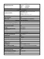
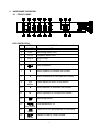
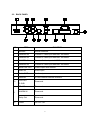
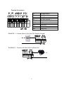
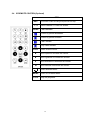
GT804M
USER MANUAL
4 CHANNEL
DIGITAL VIDEO RECORDER
INSTRUCTION MANUAL
To obtain the best performance and ensure device function correctly, please read this
instruction manual carefully and completely.
INSTRUCTION MANUAL
To obtain the best performance and ensure device function correctly, please read this instruction manual
carefully and completely.
FCC Compliance
USER-INSTALLER CAUTION: YOUR AUTHORITY TO OPERATE THIS FCC VERIFIED EQUIPMENT
COULD BE VOIDED IF YOU MAKE CHANGES OR MODIFICATIONS NOT EXPRESSLY APPROVED BY
THE PARTY RESPONSIBLE FOR COMPLIANCE TO PART 15 OF THE FCC RULES.
NOTE: THIS EQUIPMENT HAS BEEN TESTED AND FOUND TO COMPLY WITH THE LIMITS FOR A
CLASS A DIGITAL DEVICE, PURSUANT TO PART 15 OF THE FCC RULES. THESE LIMITS ARE
DESIGNED TO PROVIDE REASONABLE PROTECTION AGAINST HARMFUL INTERFERENCE WHEN
THE EQUIPMENT IS OPERATED IN A COMMERCIAL ENVIRONMENT. THIS EQUIPMENT GENERATES,
USES, AND CAN RADIATE RADIO FREQUENCY ENERGY AND IF NOT INSTALLED AND USED IN
ACCORDANCE WITH THE INSTRUCTION MANUAL, MAY CAUSE HARMFUL INTERFERENCE TO
RADIO COMMUNICATIONS.
OPERATION OF THIS EQUIPMENT IN A RESIDENTIAL AREA IS LIKELY TO CAUSE HARMFUL
INTERFERENCE IN WHICH CASE THE USER WILL BE REQUIRED TO CORRECT THE INTERFERENCE
AT HIS OWN EXPENSE.
THIS CLASS A DIGITAL APPARATUS MEETS ALL REQUIREMENTS OF THE CANADIAN
INTERFERENCE-CAUSING EQUIPMENT REGULATIONS.
WARNINGS, CAUTIONS & COPYRIGHT
WARINGS
TO REDUCE THE RISK OF FIRE OR ELECTRIC SHOCK, DO NOT EXPOSE THIS PRODUCT TO RAIN OR
MISTURE.
DO NOT INSERT ANY METALLIC OBJECT THROUGH VENTILATION GRILLS.
CAUTION
CAUTION
RISK OF ELECTRIC SHOCK
DO NOT OPEN
CAUTION: TO REDUCE THE RISK OF ELECTRIC SHOCK.
DO NOT REMOVE COVER (OR BACK).
NO USER-SERVICEABLE PARTS INSIDE.
REFER SERVICING TO QUALIFIED SERVICE PERSONNEL.
Explanation of Graphical Symbols
The lightning flash with arrowhead symbol, within an equilateral triangle, is intended to alert
the user to the presence of insinuated "dangerous voltage" within the products enclosure
that may be of sufficient magnitude to constitute a risk of electric shock to persons.
The exclamation point within an equilateral rhombus is intended to alert the user to the
presence of important operating and maintenance (servicing) instruction in the literature
accompanying the product.
USERS OF THE SYSTEM ARE RESPONSIBLE FOR CHECKING AND COMPLYING WITH ALL FEDERAL,
STATE, AND LOCAL LAWS AND STATUTES COIPCERNING THE MONITORING AND RECORDING OF
VIDEO AND AUDIO SIGNALS. ULTRAK SHALL NOT BE HELD RESPONSIBLE FOR THE USE OF THIS
SYSTEM IN VIOLATION OF CURRENT LAWS AND STATUTES.
COPYRIGHT
THE TRADEMARKS MENTIONED IN THE MANUAL ARE LEGALLY REGISTERED TO THEIR
RESPECTIVE COMPANIES.
2
TABLE OF CONTENTS
1
2
INTRODUCTION .......................................................................................................................4
1.1
FEATURE.......................................................................................................................4
1.2
SPECIFICATION...........................................................................................................4
HARDWARE OVERVIEW .......................................................................................................7
2.1
FRONT PANEL .............................................................................................................7
2.2
2.3
2.4
2.5
BACK PANEL ...............................................................................................................9
EXTERNAL ALARM(reserved) ...............................................................................10
IR REMOTE CONTROL(Optional)..........................................................................12
RS-485 CONTROLLER (reserved).........................................................................13
2.6
PTZ (PAN, TILT AND ZOOM) CAMERA & JOYSTICK CONTROLLER
(reserved) ................................................................................................................................13
2.7
VGA OUTPUT(reserved) ..........................................................................................15
2.8
NETWORK ...................................................................................................................15
3
SYSTEM SETUP.....................................................................................................................16
3.1
MENU SETUP INTERFACE(GUI)............................................................................16
3.2
LIVE VIEWING AND POP-UP MENU .....................................................................18
3.3
3.4
3.5
3.6
4
5
6
CAMERA SETUP......................................................................................................19
MOTION SETUP .......................................................................................................21
RECORD SETUP......................................................................................................21
ALARM SETUP.........................................................................................................22
3.7
HARD DISK SETUP .................................................................................................23
3.8
NETWORK SETUP...................................................................................................24
3.9
BACKUP SETUP ......................................................................................................25
DVR PLAYBACK ....................................................................................................................27
4.1
TIME SEARCH ............................................................................................................27
4.2
EVENT SEARCH ........................................................................................................28
DVR & USB BACKUP PLAYBACK ....................................................................................29
5.1
MAIN SCREEN SETTING .........................................................................................29
5.2
PLAYER USER INTERFACE ...................................................................................30
NETWORK VIEWING & PLAYBACK .................................................................................32
6.1 IP ADDRESS SETUP ON PC SITE ..............................................................................32
6.2 OPTIONAL MICROSOFT INTERNET EXPLORER SETUP: ...................................33
6.3 LOGIN ................................................................................................................................34
6.4 LIVE VIEWING..................................................................................................................35
6.5 CONFIGURE .....................................................................................................................36
APPENDIX A: RECORDING TIME LAPSE ...............................................................................44
APPENDIX B: HDD/ USB DRIVE COMPATIBLE TABLE .......................................................46
APPENDIX C: HARD DISK INSTALLATION.............................................................................47
3
1
INTRODUCTION
1.1 FEATURE
MPEG-4 Video Compression.
Resolution:
Real-time 720×480 ( NTSC )/ 720×576 ( PAL )
Recording 720x240 ( NTSC )/ 720x288 ( PAL )
Audio Backup / Audio Streaming.
Internal SATA Hard Disk Support.
Graphic User Interface ( GUI ).
Mouse/ IR Remote Controller Support.
USB Back Up/ Firmware Update
Compact Size, Easy Space Arrangement
Support Smart Phone and PDA.
1.2 SPECIFICATION
VIDEO
Triplex
MODE
NTSC
IMAGE SYSTEM
PAL
LIVE-TIME RESOLUTION
720×480
720×576
LIVE-TIME DISPLAY RATE
4 × 30 Frame / Sec
4 × 25 Frame / Sec
SPLIT SCREEN
1, 4
VIDEO INPUT
BNC × 4
VIDEO LOOPING
No
VIDEO OUTPUT (BNC)
BNC × 1
VIDEO OUTPUT (VGA)
Yes (Option)
AUDIO
AUDIO INPUT
RCA × 1
AUDIO OUTPUT
RCA × 1
AUDIO BACKUP
Yes
AUDIO STREAMING
Yes
RECORDING
COMPRESSION TYPE
MPEG-4
RECORDING RESOLUTION
720×240, 360x240
720×288, 360x288
RECORDING RATE (CIF)
360 x 240 up to 120 PPS
360 x 288 up to 100 PPS
RECORDING RATE (FIELD)
720 x 240 up to 30 PPS
720 x 288 up to 25 PPS
4
:2K Bytes
Low
Medium :4.2K Bytes
High
:6.2K Bytes
Best
:8K Bytes
12 Manual / Schedule
COMPRESSION RATE
RECORDING MODE
PLAYBACK & SEARCH
PLAYBACK SPEED
Fast Forward X 2 X 8 X 16 X32
Fast Backward X32
field by field Playback
Pause
Slow Motion Playback X1/2 X1/4
X64
TIME SEARCH
Yes
EVENT SEARCH
Yes
EVENT LIST
3000 records per H.D.D (Maximum)
OSD & CONTROL INTERFACE
TITLE
8 Characters
ON SCREEN DISPLAY & SETUP
Time / Date / Setup Menu
GRAPHIC USER INTERFACE (GUI)
Yes
DVR CONTROL PANEL
Yes
MOUSE
Yes (Option)
IR REMOTE CONTROLLER
Yes (Option)
IE BROWSER
Yes
PLAYER
F4 Viewer
STORAGE & BACKUP DEVICE
INTERNAL HDD SUPPORT
SATA HDD x 1
USB BACKUP
Yes
NETWORK
ETHERNET
Yes
ETHERNET COMPRESSION FORMAT MPEG-4
DDNS
Yes
E-MAIL & FTP
Yes
NETWORK IP
Static/ Dynamic/ PPPoE
MULTI-REMOTE CLIENT
Yes ( 5 Clients at the same time available)
PDA/ CELL PHONE SUPPORT
Yes
ALARM
MOTION DETECTION
Yes
MOTION DETECTION AREA
30 x 24 grids
MOTION DETECTION SENSITIVITY
1-100
VIDEO LOSS DETECTION
Yes
5
ALARM RECORDING
Yes
BUZZER
Yes
SETUP & OTHER FUNCTIONS
PASSWORD CONTROL
Two levels, one for system and the other for HDD format
KEY-LOCK
Yes
MULTI-LANGUAGE
Yes
FIRMWARE UPDATE
USB Host
OTHERS
POWER INPUT
DC 12V
POWER CONSUMPTION (W)
17W
DIMENSIONS (W x H x D)
218mm (W) × 44mm (H) × 202mm (D)
WEIGHT (kg)
1.4kg
OPERATION TEMPERATURE
0 - 45 ℃
ATTENTION:
:A. PLEASE format the hard disk before changing the recording resolution.
Different record resolution cannot be stored in the same hard disk.
Failing to do so may cause data lost or hard disk damage!!
B. DVR needs to STOP recording before processing USB backup function.
C. DVR needs to STOP recording before processing USB firmware update
function.
D. DVR system will reboot after changing recording quality setup.
6
2
HARDWARE OVERVIEW
2.1 FRONT PANEL
DVR OPERATION
NO.
ITEM
1
POWER
2
REC
Recording status LED.
3
PLAY
Playback status LED.
4
H.D.D
5
O
H.D.D. LED.
IR Sensor for remote control.
6
DVR Function
Power status LED.
USB connector.
7
▲
Move upward or increase the number.
8
▼
Move downward or decrease the number.
9
MENU
Press MENU to enter or exit MENU.
10
◄
Move leftward or decrease the number.
11
►
Move rightward or increase the number.
12
Recording button.
REC
13
14
15
Rew search
STOP
Pause
Fast Backward x 32.
Press STOP to stop playback or recording.
Pause & Field by Field Forward.
7
16
Fast Forward ×2, ×8, ×16, x32, ×64.
F.Fwd
17
PLAY button & Get into Quick Time Search.
PLAY
18
19
20
21
22
23
1
2
3
4
Quad
Channel One Full Screen & Number: One.
Channel Two Full Screen & Number: Two.
Channel Three Full Screen & Number: Three.
Channel Four Full Screen & Number: Four.
Quad screen: All cameras are displayed.
Confirmation and Backup.
FRONT PANEL KEY COMBINATION
Auto Swap:Press “Quad”, then press “>>” within 5 seconds.
Zoom Function:Press”Enter” while in the single channel mode.
HDD Information:Press ”Enter” while in the Quad mode.
8
2.2 BACK PANEL
NO.
ITEM
FUNCTION
1
MOUSE
Mouse interface.
2
CAMERA IN
Camera 1 video input with BNC connector.
3
CAMERA IN
Camera 2 video input with BNC connector.
4
CAMERA IN
Camera 3 video input with BNC connector.
5
CAMERA IN
Camera 4 video input with BNC connector.
6
MONITOR OUT
Video output with monitor
7
Audio IN
Audio input.
8
Audio OUT
Audio output.
9
Ethernet
RJ-45 Ethernet network interface.
10
VGA OUT
D-SUB
Reserved.
RS-485
Reserved.
ALARM IN
Reserved.
Relay Out
Reserved.
Power
DC 12V /3A.
11
12
9
2.3 EXTERNAL ALARM(reserved)
There are three types of alarms that the system can be configured, such as Motion
Detection Alarm, External Alarm, and Video Loss Alarm.
Motion Detection Alarm and External Alarm:
When Motion Detection or External Alarm was triggered, there are 5 possible
actions will be taken.
a. Recording speed changed from normal to alarm recording.
b. If Alarm Display Mode of Alarm Setup is ON, when the alarm is triggered, the
corresponding full screen alarm channel will be displayed automatically;
however, if the alarm is triggered and the setup is done within five seconds,
the corresponding full screen alarm channel won’t be displayed.
c. It’s optional to activate Relay.
d. Motion Detection and External Alarm both will be recorded in the event list.
In Motion Detection Record of Alarm Setup, the user can set up ON or OFF
to record the motion event or not.
e. When Motion Detection was triggered, the color of camera title will be
transformed into yellow. In addition, when External Alarm was triggered,
“ALARM” text will be displayed on the screen.
10
Terminal Connectors:
:
T+
RS-485 sends +
T-
RS-485 sends -
R-
RS-485 receives -
R+
RS-485 receives +
ALARM1-4
Camera alarm input.
GND
GND.
N.C
Relay N.C.
COM
Relay COM
N.O
Relay N.O.
EXAMPLE 1:Connect Alarm In One with PIR (Passive Infrared).
EXAMPLE 2:Connect with Alarm Siren at Relay N.O.
11
2.4 IR REMOTE CONTROL(Optional)
ITEM
REC
Press REC to start recording and press twice to stop.
1-4
Select channel 1-4 with full screen.
QUAD
Fast backward.
Picture by picture backward.
Picture by picture forward.
Fast Forward.
Play video forward.
COPY
Switch channel format.
▲
Move upward or increase the number.
►
Move rightward or increase the number.
▼
Move downward or decrease the number.
◄
Move leftward or decrease the number.
Enter selected items.
MENU
Enter or Exit Main Menu.
STOP
Stop the playback.
12
2.5 RS-485 CONTROLLER (reserved)
PIN
R+
RT+
T-
RS-485
DEFINE
RXDA
RXDB
TXDZ
TXDY
:
Data Format:
Data: 1 Byte / Parity: None / Start bit: 1 / Baud: 9600
Totally 3 bytes as follows:
1. Byte=0x10
:Broadcasting DVR
Byte=0x80+ID Number
:Joystick Control DVR (ID number:1~32)
2. Byte=Reference to the table as follows. :Commands of each button.
3. Byte= the 1st Byte+ the 2nd Byte
: Command for confirm checksum.
4-ch DVR
Command
4-ch DVR
Command
CH1
0x11
PLAY
0x52
CH2
0x12
UP
0x31
CH3
0x13
DOWN
0x32
CH4
0x14
MENU
0x20
QUAD
0x15
LEFT
0x33
RFAST
0x3A
RIGHT
0x34
STOP
0x51
SELECT
0x35
PAUSE
0x3D
ENTER
0x35
FFAST
0x3E
2.6 PTZ (PAN, TILT AND ZOOM) CAMERA & JOYSTICK CONTROLLER
(reserved)
The following diagram is for DVR connect PTZ camera with joystick controllers.
Make sure CAMERA ID, BAUD RATE (default at 9600 bps) and RS-485 +/-. If the
13
user wants to connect DVR with joystick controllers, please make sure each DVR
ID Number is unique.
Up to 128 ID
Up to 16CH
Up to 16CH
R+ R- T+ T-
R+ R- T+ T-
Dome Cam 4
CH 4
ID 4
Dome Cam 4
CH 4
ID 4
D0+ D0- D1+ D1-
A B A B
Dome Cam 3
CH 3
ID 3
Dome Cam 2
CH 2
ID 2
Dome Cam 3
CH 3
ID 3
0 1 0 1
Dome Cam 2
CH 2
ID 2
D0+ D0- D1+ D1-
Dome Cam 1
CH 1
ID 1
R+ R- T+ T-
Dome Cam 3
ID 3
Up to 128 ID
A B A B
D+ D- D+ D-
Dome Cam 2
ID 2
D+ D- D+ D-
Dome Cam 1
CH 1
ID 1
A B A B
DVR 1
ID 1
DVR 2
ID 2
Dome Cam 1
ID 1
Up to 32 ID
DATA+
DATA-
14
2.7 VGA OUTPUT(reserved)
VGA Output is optional. VGA output can connect with CRT or LCD monitor by
D-SUB connector and the user can switch different resolutions and frequencies
as follows.
Resolution
Frequency
VGA
640×480
56Hz
SVGA
800×600
60Hz
XGA
1024×768
70Hz
SXGA
1280×1024
75Hz
2.8 NETWORK
When the DVR is turned on, it will detect the network connection automatically. If
without network connection, the network function will be disabled. Thus, please
make sure the network connection before turning on the DVR.
15
3
SYSTEM SETUP
3.1 MENU SETUP INTERFACE(GUI)
A.
CAMERA SET
E.
HARD DISK SETUP
B.
MOTION SETUP
F.
NETWORK SETUP
C.
RECORD SETUP
G.
BACKUP SETUP
16
D.
ALARM SETUP
H.
17
SYSTEM SETUP
3.2 LIVE VIEWING AND POP-UP MENU
NOTE:The pop-up menu can be activated by moving the mouse cursor to the
bottom of the live viewing screen.
A.
GUI MENU BAR
With live viewing mode, press this button to get into the GUI menu.
B.
DISK INFORMATION
With live viewing mode, press this button to display disk information.
C.
DIGITAL ZOOM
In the full screen mode, right-click or left-click the mouse to zoom in or zoom
out the image.
D.
AUDIO CONTROL
Press this button to turn the audio on or off。
E.
DISPLAY CONTROL
Within live-viewing or playback mode, use display control to switch the camera
channel.
RECORD AND PLAYBACK CONTROL
Same as front panel controller and remote controller. Please see chapter 2.1 &
4 for more detail.
F.
18
3.3
CAMERA SETUP
Press ▲ or ▼ to select items.
Press ◄ or ► to change values.
Press SET to see more options.
A. CAMERA
Press ◄ or ► to switch channels.
B. VIDEO ADJUST
B.1 CONTRAST
Press ◄ or ► to change contrast level.
B.2 BRIGHTNESS
Press ◄ or ► to change brightness level.
B3. HUE
Press ◄ or ► to change HUE level.
B4. COLOR
Press ◄ or ► to change color level.
B5. SHAPRNESS
Press ◄ or ► to change sharpness level.
C. CAMERA TITLE
Use mouse to select and change character.
19
D. DISPLAY
Press ◄ or ► to change value for the corresponding camera would be
displayed on the screen or not.
E. AUTO SWITCH
Press ◄ or ► to ON/OFF auto switch.
20
3.4
MOTION SETUP
Press ▲ or ▼ to select items.
Press ◄ or ► to change values.
Press SET to see more options.
A. CAMERA
Press ◄ or ► to switch channels.
B. MOTION DETECT
Press ◄ or ► to change value for motion detect function.
C. BUZZER
Press ◄ or ► to change value for buzzer while motion detected.
D. SENSITIVITY
Press ◄ or ► to change sensitivity value from 001 (minimum) to 100
(maximum).
E. AREA SETUP
1. Press SET to enter motion area setting.
2. Use mouse to select which block is needed.
3. Left-Click mouse to see more options or exit the setup.
3.5
RECORD SETUP
Press ▲ or ▼ to select items.
Press ◄ or ► to change values.
Press SET to see more options.
A. RESOULTION
Press ◄ or ► to switch record resolution.
720 x 240 (NTSC)/ 720 x 288 (PAL).
360 x 240 (NTSC)/ 360 x 288 (PAL).
ATTENTION:
:PLEASE format the hard disk before changing the
recording resolution. Different record resolution
cannot be stored in the same hard disk. Failing to
do so may cause data lost or hard disk damage!!
21
B. NORMAL RECORD PPS
Press ◄ or ► to switch PPS in normal recording.
C. ALARM RECORD PPS
Press ◄ or ► to switch PPS in alarm recording.
D. ALARM RECORD DURATION
Press ◄ or ► to set dwell time of alarm recording.
E. QUALITY
Press ◄ or ► to switch quality to LOW/ MEDIUM/ HIGH/ BEST.
F. RECORD MODE
Press ◄ or ► to switch record mode to ALWAYS/ MOTION/ SCHEDULE /
OFF.
G. AUDIO RECORD
Press ◄ or ► to switch AUDIO RECORD ON or OFF.
H. SCHEDULE SETUP
Press SET to get into schedule setup menu。
1. Use mouse to select schedule day/ time/ mode.
2. Click
3.6
to save change and exit.
ALARM SETUP
Press ▲ or ▼ to select items.
Press ◄ or ► to change values.
Press SET to see more options.
22
A. ALARM DISPLAY MODE
Press ◄ or ► to change value for ALARM DISPLAY MODE with full screen.
B. VIDEO LOSS DETECT
Press ◄ or ► to switch VIDEO LOSS ALARM ON or OFF.
C. EVENT LOG SETUP
Press SET to change value for MOTION EVENT / VIDEO LOSS EVENT to
ON / OFF.
D. BUZZER TIME SETUP
Press SET to set dwell time of BUZZER/ ALARM.
3.7
HARD DISK SETUP
Press ▲ or ▼ to select items.
Press ◄ or ► to change values.
Press SET to see more options.
A. OVERWRITE MODE
Press ◄ or ► to change value OVERWRITE MODE ON or OFF.
B. CAPACITY WARNING
Press ◄ or ► to change value to 20/ 15/ 10 or 5% with non-overwrite mode.
When LEFT RATIO is below the setting, it will enable AUDIBLE ALARM (If
AUDIBLE ALARM of BUZZER of ALARM SETUP is ON).
C. HDD INFORMATION
Press SET to display HDD information.
D. HDD FORMAT SETUP
D-1. HDD PASSWORD PROTECT
Press ◄ or ► to change value for hard disk format password protection.
DC-2. HDD PASSWORD
Press SET then use mouse to change password.
Default password: 1111
23
D-3. FORMAT
Press SET to get into FORMAT setup.
Press YES or NO to execute.
3.8
NETWORK SETUP
Press ▲ or ▼ to select items.
Press ◄ or ► to change values.
Press SET to see more options.
A. IP MODE
Press ▲ or ▼ to select items and ◄ or ► to change to STATIC IP or DHCP.
B. HTTP PORT
Press ▲ or ▼ to select items and ◄ or ► to change WEB PAGE PORT.
C. IP ADDR
Press ▲ or ▼ to select items and ◄ or ► to change IP ADDRESS.
D. NETMASK
Press ▲ or ▼ to select items and ◄ or ► to change SUBNET MASK.
E. GATEWAY
Press ▲ or ▼ to select items and ◄ or ► to change Default GATEWAY.
F. DNS1
Press ▲ or ▼ to select items and ◄ or ► to change DNS.
G. DNS2
Press ▲ or ▼ to select items and ◄ or ► to change OTHER DNS.
H. PPPoE
H-1. PPPoE SETTING
Press◄ or ► to ENABLE / DISABLE PPPoE.
H-2. USER NAME
Use mouse to setup user name for ADSL account.
H-3 PASSWORD
24
Use mouse to setup password for ADSL account.
H-4 STATE
Press SET to display status of PPPoE。
I. DDNS
I-1.DDNS SETTING:
:Press◄ or ► to set DDNS ENABLE / DISABLE.
I-2 PROVIDER:
:Press◄ or ► to select DDNS provider.
I-3 USER NAME:
:Press SET to setup user name.
I-4 PASSWORD:
:Press SET to setup password.
I-5 UPDATE SCHEDULE:
: Use SET to dwell time of updating schedule.
I-6 STATE:
:Press SET to display status of DDNS。
3.9
BACKUP SETUP
Due to each USB device with different USB driver ICs, their compatibilities differ,
too. This system is compatible with most of USB flash memory. If there is
compatible issue, please refer to APPENDIX B. In addition, please format USB
flash memory with FAT32.
BEFORE BACKUP
A. In live viewing mode, insert USB device into a USB port of the DVR.
B. Get into playback mode by PLAY TIME SEARCH or EVENT LIST SEARCH
and play back videos that are going to be as backup.
25
VIDEO BACKUP
In multiplexer or full screen mode, press COPY to start backup and press COPY
to end backup. The system will backup automatically.
BACKUP FILE NAME
Each backup file will be named as START TIME.
EXAMPLE: 11201817.IN is Nov. 6th 18:17
AFTER BACKUP
After backup, the system will copy “F4Viewer.exe” automatically on USB device
for the user to play back backup file.
3.10
SYSTEM SETUP
Press ▲ or ▼ to select items.
Press ◄ or ► to change values.
Press SET to see more options.
A. DATE / TIME SETUP
Press SET to set Date / TIME.
B. SYSTEM TYPE
Please update firmware to change system type.
C. KEYBOARD LOCK
Press ◄ or ► to switch ON/ OFF.
OFF:UNLOCK.
ON: LOCK.
After KEYBOARD LOCK mode setup, please set up PASSWORD
Without password, un-authorized users could access into SYSTEM SETUP
and make changes of settings easily.
D. ID NUMBER
Press ◄ or ► to change values.
When connecting with the joystick controller, ID NUMBER is required to make
difference of each DVR.
E. DISPLAY SETUP
Press SET to ENABLE or DISABLE display of CAMERA TITLE / DVR STATUS
/ DATE / TIME.
F. LANGUAGE
Press ◄ or ► to change on-screen-display (OSD) language.
G. PASSWORD PROTECTION
Press ▲ or ▼ to select items and ◄ or ► to change values.
26
Default password: 1111.
H. FIRMWARE UPDATE
Press YES to start firmware update. After updated, the DVR will reboot
automatically. At this moment, please do not turn off the DVR manually.
NOTE: Please format USB flash memory with FAT32.
I. LOAD DEFAULT
Press YES to load the system default setting, and “LOAD DEFAULT!” will be
displayed on the screen until recover finished.
4
DVR PLAYBACK
Click the playback button on the
pop-up menu.
Note: the pop-up menu can be
activated by moving the mouse
cursor to the bottom of the live
viewing screen.
4.1 TIME SEARCH
Double click mouse to trigger play time search.
Please set the start and end time to search.
27
4.2 EVENT SEARCH
Double click mouse to trigger event search.
Please select the event to playback。
NOTE: Display the type of the event as follows.
POWER
If the DVR got power loss, it will record the date and time of
rebooting.
RECORD If REC. button has been pressed, it will record the date and time
in the event list.
V.LOSS
When a camera signal is lost, it will record the date, time, and
corresponding channel.
ALARM
When ALARM is triggered, it will record the date, time, and
corresponding channel.
MOTION When MOTION is detected, it will record the date, time, and
corresponding channel.
28
5
DVR & USB BACKUP PLAYBACK
SYSTEM REQUIREMENT:
CPU: Intel Pentium III 1G or above.
MEMORY: 512 MB or above.
VGA: 32MB/64MB or above.
OS: Microsoft Windows XP SP2 or above.
VGA RESOLUTION: 1024*768 or above.
5.1 MAIN SCREEN SETTING
A. MAIN SCREEN
B. Open a disk drive that is with USB Backup files (e.g. F:) or other folder
that is with Backup files.
Each backup file will be named as START TIME.
EXAMPLE: 11201817.IN is Nov. 6th 18:17
29
C. Select HDD PLAY mode or FILE PLAY mode, and then open the file for
playback.
Open the file for
Select HDD PLAY mode
playback.
or FILE PLAY mode
5.2 PLAYER USER INTERFACE
Open the file for
playback.
Under HDD PLAY
mode, user can use
TIME/ EVENT
SEARCH & COPY
function
5.3 AVI BACKUP & SNAPSHOT
30
A. AVI BACKUP
User can save the
playing video file as AVI
format
B. SNAPSHOT
Click on the left of mouse to
use SNAPSHOT function
31
6 NETWORK VIEWING & PLAYBACK
CPU: Intel Pentium III 1G or above.
Memory: 512 MB or above.
VGA: 32MB/64MB or above.
OS: Microsoft Windows XP SP2 or above.
VGA RESOLUTION: 1024*768 or above.
6.1 IP ADDRESS SETUP ON PC SITE
Install cameras inside in LAN or use network cable to connect with PC. This is for
IPInstallerEng.exe to set up IP address of cameras. If OS is Windows XP SP2 or
above, the following Windows Security Alert will popup. Then, please click on
Unblock.
Then, IPInstallerEng.exe will popup:
DVR default IP address is 192.168.1.220
NOTE: Please input correct network parameters without blank spaces.
On Device Lists, it lists all servers. Click on one server and then its IP setting will
show on the right side. After editing the parameters and clicking on Submit, the
following dialogue box will popup. And, it will reboot the device with new
32
parameters.
6.2 OPTIONAL MICROSOFT INTERNET EXPLORER SETUP:
OPTION 1: DISABLE ACTIVEX WARNING
A. IE Tools Internet Options Security Custom Level Security
Settings Download unsigned ActiveX controls Enable or Prompt
(recommend).
B. IE Tools Internet Options Security Custom Level Security
Settings Initialize and script ActiveX controls not marked as safe Enable or Prompt (recommend).
1
2
3
4
33
5
Above three options are all based on select as the prompt.
As indicated in the dialogue box. Please select "YES."
OPTION 2: ADD TO TRUSTED SITES
IE Tools Internet Options Security Trusted sites Sites
6.3 LOGIN
A. INSTALL ACTIVEX
B.
START INSTALL ACTIVEX
34
C.
ACCOUNT & PASSWORD LOGIN
After IP setup and connect to network or LAN, type IP address on IE Browser
directly. The following User name & Password Login window will popup.
Default user name: admin
Default password: admin
6.4 LIVE VIEWING
DVR Configuration
Stop
Fast Forward
REC
DVR Status
System Time
Screen Format
Fast Backward
A. DVR CONFIGURATION
Get into DVR network menu.
Play, Playback or Time Search
B. SYSTEM TIME
Live viewing mode: The current live viewing time.
C. SCREEN FORMAT
Switch screen format and click twice to switch different channels with full
screen.
35
Snapshot.
D.
E.
Full Screen. Click again to return.
F.
REC. Videos are saved as AVI file.
G.
Playback Time Search.
Click
, the following Time Search….. window will popup.
EVENT LIST
Select a HDD to list EVENT LIST on Master or Slave HDD. Click the left
button of the mouse twice to play back the selected event.
TIME SEARCH
Input Date and Time and click Search to play back.
6.5 CONFIGURE
A. System - System Information
36
A-1 SYSTEM INFORMATION
SERVER NAME: This name will show on the IP Installer.
LANUGAGE:
:There are English, Traditional Chinese, and Simplified
Chinese. After selecting one language, the following dialogue box will
popup and ask the user to confirm.
B. SYSTEM – USER MANAGEMENT
User Management provides 3 levels of limits of authority: Administrator (the
37
highest), User, and Anonymous.
Default administrator account:
Username: admin
Password: admin
B-1 ANONYMOUS USER LOGIN:
YES: Accept anonymous user login without password as guest login.
NO: Anonymous login unacceptable.
B-2 USER MANAGEMENT:
Add: Input Username and Password and then click on Add/Set to save.
Modify: Click on selected User name on User List and the following
window will popup. After inputting Password and Confirm Password, click
on OK.
Remove: Click on selected User name on the user list and click on
Remove.
C. NETWORK – IP SETTING
Click browse to select firmware to upgrade
Click start to reboot the DVR.
D. NETWORK – IP SETTING
38
D-1 IP ASSIGNMENT
DHCP: In Dynamic Host Configuration Protocol (DHCP) mode, DHCP
server will get setting done automatically.
STATIC IP: Please input IP address, Subnet Mask, and Gateway based
on network environment.
D-2
PORT ASSIGNEMENT
With IP Share (Router), the following Ports needed to be adjusted in
case of conflict.
E. NETWORK – PPPoE
E-1 PPPoE SETTING
Click on Enabled to enable ADSL dial function.
Username: Username for ADSL account.
39
Password: Password for ADSL account.
After dialed successfully, new IP address will appear.
E-2 SEND MAIL AFTER DIALED
Click on Enabled to enable SEND MAIL AFTER DIALED function.
E-3 SUBJECT
Mail subject.
F. NETWORK / DDNS SETTING
Click on Enabled to enable DDNS function.
F-1 DYNDNS.ORG
DDNS SETTING - DYNDNS.ORG
PROVIDER: Select dyndns.org
HOSTNAME: The registered hostname in DYNDNS.ORG.
USERNAME: The registered username in DYNDNS.ORG.
PASSWORD: The registered password in DYNDNS.ORG.
SCHEDULE UPDATE: A period of time to update IP address.
40
STATE
1. Updating: Information update.
2. Idle: Stop service.
3. DDNS registered successfully, now log by
http://<username>.ddns.camddns.com: Registered successfully.
4. Updating Failed, the name is already registered.
5. Updating Failed, please check your internet connection.
F-2 DDNS.CAMNNDS.COM
DDNS SETTING – DDNS.CAMDDNS.COM
PROVIDER: Select ddns.camddns.com
USERNAME: The registered username in DDNS.CAMDDNS.COM.
SCHEDULE UPDATE: A period of time to update IP address.
STATE
1. Updating: Information update.
2. Idle: Stop service.
3. DDNS registered successfully, now log by
http://<username>.ddns.camddns.com: Registered successfully.
4. Updating Failed, the name is already registered.
5. Updating Failed, please check your internet connection.
G. AUDIO SETING
Enabled: Enable the audio transmission from DVR to PC.
Disabled: Disable the audio transmission from DVR to PC.
41
H. EVENT SETTING
H-1 MOTION DECTECTION ACTION SETTING
Motion detection action can be set up on each channel individually. After
the motion is detected, it will trigger emails or upload files to FTP.
H-2 SUBJECT
Mail Subject.
H-3 INTERVAL
The interval time between two emails in case the mail is sent out too
frequently.
I. EVENT SETTING/ ALARM SETTING
I-1 EXTERNAL ALARM ACTION SETTING
External alarm action can be set up on each channel individually. After the
external alarm action is detected, it will trigger emails or upload files to
FTP.
I-2 SUBJECT
Mail Subject.
I-3 INTERVAL
The interval time between two emails in case the mail is sent out too
frequently.
42
J. EVENT SETTING/ MAIL & FTP
J-1 MAIL & FTP SETTING
Mail and FTP settings are for motion detection action and external alarm
action. When both actions are detected, it will trigger emails or upload files
to FTP.
43
APPENDIX A: RECORDING TIME LAPSE
NTSC
80GB HDD
PPS (Picture Per Sec.)
Record
Quality
Best
High
Middle
Low
30
93 hr
125 hr
186 hr
373 hr
15
186 hr
250 hr
372 hr
746 hr
10
279 hr
375 hr
558 hr
1119 hr
5
558 hr
750 hr
1116 hr
2238 hr
3
930 hr
1250 hr
1860 hr
3730 hr
2
1395 hr
1875 hr
2790 hr
5595 hr
1
2790 hr
3750 hr
5580 hr
11190 hr
3
1395 hr
1880 hr
2790 hr
5595 hr
2
2093 hr
2820 hr
4185 hr
8393 hr
1
4185 hr
5640 hr
8370 hr
16785 hr
3
1860 hr
2500 hr
3720 hr
7460 hr
2
2790 hr
3750 hr
5580 hr
11190 hr
1
5580 hr
7500 hr
11160 hr
22380 hr
3
2790 hr
3750 hr
5580 hr
11190 hr
2
4185 hr
5625 hr
8370 hr
16785 hr
1
8370 hr
11250 hr
16740 hr
33570 hr
3
3720 hr
5000 hr
7440 hr
14920 hr
2
5580 hr
7500 hr
11160 hr
22380 hr
1
11160 hr
15000 hr
22320 hr
44760 hr
3
4650 hr
6250 hr
9300 hr
18650 hr
2
6975 hr
9375 hr
13950 hr
27975 hr
1
13950 hr
18750 hr
27900 hr
55950 hr
3
5580 hr
7500 hr
11160 hr
22380 hr
2
8370 hr
11250 hr
16740 hr
33570 hr
1
16740 hr
22500 hr
33480 hr
67140 hr
120GB HDD
PPS (Picture Per Sec.)
Record
Quality
Best
High
Middle
Low
30
140 hr
188 hr
275 hr
560 hr
15
279 hr
376 hr
559 hr
1119 hr
30
186 hr
250 hr
372 hr
746 hr
15
372 hr
500 hr
744 hr
1492 hr
10
419 hr
564 hr
837 hr
1679 hr
5
837 hr
1128 hr
1674 hr
3357 hr
160GB HDD
PPS (Picture Per Sec.)
Record
Quality
Best
High
Middle
Low
10
558 hr
750 hr
1488 hr
2984 hr
5
1116 hr
1500 hr
2232 hr
4476 hr
250GB HDD
PPS (Picture Per Sec.)
Record
Quality
Best
High
Middle
Low
30
279 hr
375 hr
558 hr
1119 hr
15
558 hr
750 hr
1116 hr
2238 hr
10
837 hr
1125 hr
1674 hr
3357 hr
5
1674 hr
2250 hr
3348 hr
6714 hr
300GB HDD
PPS (Picture Per Sec.)
Record
Quality
Best
High
Middle
Low
30
372 hr
500 hr
744 hr
1492 hr
15
744 hr
1000 hr
1488 hr
2984 hr
30
465 hr
625 hr
930 hr
1865 hr
15
930 hr
1250 hr
1860 hr
3730 hr
30
558 hr
750 hr
1116 hr
2238 hr
15
1116 hr
1500 hr
2232 hr
4476 hr
10
1116 hr
1500 hr
2232 hr
4476 hr
5
2232 hr
3000 hr
4464 hr
8952 hr
400GB HDD
PPS (Picture Per Sec.)
Record
Quality
Best
High
Middle
Low
10
1395 hr
1875 hr
2790 hr
5595 hr
5
2790 hr
3750 hr
5580 hr
11190 hr
500GB HDD
PPS (Picture Per Sec.)
Record
Quality
Best
High
Middle
Low
10
1674 hr
2250 hr
3348 hr
6714 hr
5
3348 hr
4500 hr
6696 hr
13428 hr
44
PAL
80GB HDD
PPS (Picture Per Sec.)
Record
Quality
Best
High
Middle
Low
25
112 hr
167 hr
223 hr
448 hr
12
223 hr
334 hr
447 hr
896 hr
25
168 hr
251 hr
330 hr
672 hr
12
335 hr
502 hr
671 hr
1343 hr
10
279 hr
418 hr
558 hr
1119 hr
5
558 hr
835 hr
1116 hr
2238 hr
3
930 hr
1336 hr
1860 hr
3730 hr
2
1395 hr
2005 hr
2790 hr
5595 hr
1
2790 hr
4175 hr
5580 hr
11190 hr
3
1395 hr
2008 hr
2790 hr
5595 hr
2
2093 hr
3012 hr
4185 hr
8393 hr
1
4185 hr
6275 hr
8370 hr
16785 hr
3
1860 hr
2672 hr
3720 hr
7460 hr
2
2790 hr
4008 hr
5580 hr
11190 hr
1
5580 hr
8350 hr
11160 hr
22380 hr
3
2790 hr
4008 hr
5580 hr
11190 hr
2
4185 hr
6012 hr
8370 hr
16785 hr
1
8370 hr
12525 hr
16740 hr
33570 hr
3
3720 hr
5344 hr
7440 hr
14920 hr
2
5580 hr
8016 hr
11160 hr
22380 hr
1
11160 hr
16700 hr
22320 hr
44760 hr
3
4650 hr
6680 hr
9300 hr
18650 hr
2
6975 hr
10020 hr
13950 hr
27975 hr
1
13950 hr
20875 hr
27900 hr
55950 hr
3
5580 hr
8016 hr
11160 hr
22380 hr
2
8370 hr
12024 hr
16740 hr
33570 hr
1
16740 hr
25050 hr
33480 hr
67140 hr
120GB HDD
PPS (Picture Per Sec.)
Record
Quality
Best
High
Middle
Low
10
419 hr
628 hr
837 hr
1679 hr
5
837 hr
1255 hr
1674 hr
3357 hr
160GB HDD
PPS (Picture Per Sec.)
Record
Quality
Best
High
Middle
Low
25
149 hr
334 hr
447 hr
895 hr
12
447 hr
668 hr
893 hr
1791 hr
10
744 hr
835 hr
1488 hr
2984 hr
5
1116 hr
1670 hr
2232 hr
4476 hr
250GB HDD
PPS (Picture Per Sec.)
Record
Quality
Best
High
Middle
Low
25
335 hr
501 hr
670 hr
1343 hr
12
670 hr
1002 hr
1340 hr
2686 hr
10
837 hr
1253 hr
1674 hr
3357 hr
5
1674 hr
2505 hr
3348 hr
6714 hr
300GB HDD
PPS (Picture Per Sec.)
Record
Quality
Best
High
Middle
Low
25
447 hr
668 hr
893 hr
1791 hr
12
893 hr
1336 hr
1786 hr
3581 hr
25
558 hr
835 hr
1116 hr
2238 hr
12
1116 hr
1670 hr
2232 hr
4476 hr
25
670 hr
1002 hr
1340 hr
2686 hr
12
1340 hr
2004 hr
2678 hr
5371 hr
10
1116 hr
1670 hr
2232 hr
4476 hr
5
2232 hr
3340 hr
4464 hr
8952 hr
400GB HDD
PPS (Picture Per Sec.)
Record
Quality
Best
High
Middle
Low
10
1395 hr
2088 hr
2790 hr
5595 hr
5
2790 hr
4175 hr
5580 hr
11190 hr
500GB HDD
PPS (Picture Per Sec.)
Record
Quality
Best
High
Middle
Low
10
1674 hr
2505 hr
3348 hr
6714 hr
5
3348 hr
5010 hr
6696 hr
13428 hr
45
APPENDIX B: HDD/ USB DRIVE COMPATIBLE TABLE
HDD COMPATIBLE TABLE
Brand
Model
Capacity
Speed(RPM)
SEAGATE
ST380815AS
80G
7200 10
SEAGATE
ST3160815AS
160G
7200 10
SEAGATE
ST3250620AS
250G
7200 10
SEAGATE
ST3400620AS
400G
7200 10
SEAGATE
ST3750640AS
750G
7200 10
MAXTOR
STM3250820AS
250G
7200
MAXTOR
STM3250824AS
250G
7200
WD
WD800AAJS-00PSA0
80G
7200
WD
WD2500AAKS-00SBA0
250G
7200
WD
WD4000YS-01MPB1
400G
7200
HITACHI
HDS728080PLA380
82.3G
7200
HITACHI
HDS721616PLA380
164G
7200
HITACHI
HDT725032VLA360
320G
7200
USB DRIVE COMPATIBLE TABLE
Brand
Model
Capacity
Kingston
DataTraveler II+
512MB
Kingston
DataTraveler II+
1GB
Transcend
TS128MJFLASHA
128MB
Transcend
JetFlash 110
512MB
Transcend
JetFlash 110
1GB
ATTENTION: DO NOT use SanDisk Cruzer® Microc series for USB Backup.
46
APPENDIX C: HARD DISK INSTALLATION
1. Hard drive jumpers need to be set properly in order to make DVR function correctly.
2. Remove DVR top cover by taking out screws from location shown below:
①
②
③
④
3. Below picture indicates a DVR without a H.D.D installed.
4. Please refer to the instruction from hard drive manufactory for correct jumper setting on (master)
mode of the hard drive, mounting the hard drive over DVR base by facing SATA interface to
DVR main board. Match screw holes from bottom to bottom of hard drive and the DVR. Turn
over the DVR from top to bottom side and then mounting up the hard drive by using screws from
47
attached accessory pack as picture below:
5. Hooking up SATA cable and power cable to the hard drive as picture below.
6. Restores top cover then hook up with power and monitor a hard drive status message
appearing if it’s been installed successful.
Attentions:
:
1. Hard drive master mode must be set correctly.
2. Make sure power cable is unplugged before hard drive installation starts.
3.
SATA cable and power cable must be hooking up correctly.
48