1
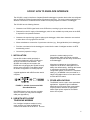
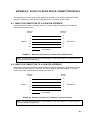
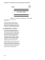
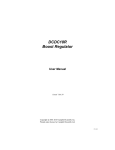
INSTRUCTION MANUAL
SC932C 9-Pin to
RS-232-DCE Interface
Revision: 6/97
C o p y r i g h t ( c ) 1 9 9 7
C a m p b e l l S c i e n t i f i c , I n c .
Warranty and Assistance
The SC932C 9-PIN TO RS232-DCE INTERFACE is warranted by
CAMPBELL SCIENTIFIC, INC. to be free from defects in materials and
workmanship under normal use and service for twelve (12) months from date of
shipment unless specified otherwise. Batteries have no warranty. CAMPBELL
SCIENTIFIC, INC.'s obligation under this warranty is limited to repairing or
replacing (at CAMPBELL SCIENTIFIC, INC.'s option) defective products.
The customer shall assume all costs of removing, reinstalling, and shipping
defective products to CAMPBELL SCIENTIFIC, INC. CAMPBELL
SCIENTIFIC, INC. will return such products by surface carrier prepaid. This
warranty shall not apply to any CAMPBELL SCIENTIFIC, INC. products
which have been subjected to modification, misuse, neglect, accidents of
nature, or shipping damage. This warranty is in lieu of all other warranties,
expressed or implied, including warranties of merchantability or fitness for a
particular purpose. CAMPBELL SCIENTIFIC, INC. is not liable for special,
indirect, incidental, or consequential damages.
Products may not be returned without prior authorization. The following
contact information is for US and International customers residing in countries
served by Campbell Scientific, Inc. directly. Affiliate companies handle repairs
for customers within their territories. Please visit www.campbellsci.com to
determine which Campbell Scientific company serves your country. To obtain
a Returned Materials Authorization (RMA), contact CAMPBELL
SCIENTIFIC, INC., phone (435) 753-2342. After an applications engineer
determines the nature of the problem, an RMA number will be issued. Please
write this number clearly on the outside of the shipping container.
CAMPBELL SCIENTIFIC's shipping address is:
CAMPBELL SCIENTIFIC, INC.
RMA#_____
815 West 1800 North
Logan, Utah 84321-1784
CAMPBELL SCIENTIFIC, INC. does not accept collect calls.
SC932C 9-Pin to RS232-DCE Interface
Table of Contents
PDF viewers note: These page numbers refer to the printed version of this document. Use
the Adobe Acrobat® bookmarks tab for links to specific sections.
1. Installation...................................................................1
2. Use with Intelligent Telephone Modems ...................1
3. Other Applications......................................................1
Appendices
A. SC932C to RS232 Device Connection Details...... A-1
A.1 Cable for Connection to a 25-Pin DCE Interface.................................A-1
A.2 Cable for Connection to a 9-Pin DCE Interface...................................A-1
B. Technical Details of Special Modes of Operation B-1
B.1
B.2
B.3
B.4
Power Modes........................................................................................B-1
Handshaking Lines ...............................................................................B-1
‘Printer Only’ Output ...........................................................................B-1
Maximum Recall Interval.....................................................................B-2
C. Specifications......................................................... C-1
List of Figures
1. SC932C Connected to RAD Short-Haul Modem........................................1
A-1. Minimum Connections for SC932C to 25-pin DCE Interface ............A-1
A-2. Minimum Connections for SC932C to 9-pin DCE Interface ..............A-1
B-1. Connections for Using SC932C in ‘Printer’ Mode .............................B-2
List of Tables
C-1. 25-Pin Male Connector Pin-out ..........................................................C-2
C-2. 9-Pin Male Connector Pin-out ............................................................C-2
i
This is a blank page.
SC932C 9-PIN TO RS232-DCE INTERFACE
The SC932C is used to interface a Campbell Scientific datalogger to modem devices that are configured
with an RS232 DCE (Data Communications Equipment) serial port. The most common application is to
allow the connection of a RAD short haul modem or third party telephone modem to a datalogger.
The SC932C has the following features:
•
Generates true RS232 signal levels to the DCE device, resulting in good noise immunity.
•
Powered from the 5V supply of the datalogger, which is also available to provide power to the DCE,
if required for line-powered modems.
•
Generates the required ring signal to wake up the datalogger, either when characters are received
or when there is a ring signal from the DCE.
•
Allows simultaneous connection of synchronous devices (e.g., Storage Modules) to the datalogger.
•
Provides a mechanism for the datalogger to control the line state of intelligent modems via DTR
handshaking control.
•
Convenient ‘jumperless’ design.
1. INSTALLATION
Use the SC12 ribbon cable (provided) to
connect the datalogger’s 9-pin CS I/O port to
the 9-pin connector on the SC932C. The
SC932C can usually be connected to the
RS232 device by plugging the SC932C directly
into the serial connector on the RS232 device.
No further configuration is normally required.
A typical application with a RAD modem would
comprise:
SC932C
FIGURE 1. SC932C Connected to RAD
Short-Haul Modem
If the RS232 device does not have a suitable
25-pin ‘D’ socket, you may need an adaptor
cable (see Appendix A).
prevent the modem staying on-line
unnecessarily, which can lead to excessive
telephone charges and also delay reconnection
to the datalogger.
Most phone modems can be configured to
respond to the DTR line, although this is not
always the default setting. Although this feature
is sometimes controlled by a hardware
configuration switch, more often it is a software
setting, e.g. AT&D2&W is the command for a
Hayes-compatible modem to force the modem
to follow the DTR status.
3. OTHER APPLICATIONS
The SC932C can be used in more specialized
applications. Appendix B gives installation
details where even lower power consumption
may be possible, and also for applications
where higher power outputs for the RS232
device are required.
2. USE WITH INTELLIGENT
TELEPHONE MODEMS
If an ‘intelligent’ telephone modem is being
used, configure it to allow the SC932C to
control its line status via the DTR line. This can
1
This is a blank page.
APPENDIX A. SC932C TO RS232 DEVICE CONNECTION DETAILS
This Appendix gives details of the cables required for connection of an SC932C to DCE type RS232
devices, if the SC932C cannot be directly plugged into the 25-pin DCE, RS232 socket.
A.1 CABLE FOR CONNECTION TO A 25-PIN DCE INTERFACE
A standard pin-to-pin cable is suitable. However, if a custom cable is to be made it must make the
following minimal connections:
SC932C
25-Pin D
Pin No.
25-Pin D
Pin No.
2
2
3
3
7
7
20
20
4*
4*
1
DCE Device
Cable Shield
FIGURE A-1. Minimum Connections for SC932C to 25-pin DCE Interface
NOTE: The link between pins 4 and 4 marked with the * may not be required — see the section on
low power operation in Appendix B.
A.2 CABLE FOR CONNECTION TO A 9-PIN DCE INTERFACE
Some newer modem-type devices are fitted with 9-pin D connectors designed to plug directly into 9-pin
serial ports as found on most ‘AT’ style PCs. Commercial adaptor cables are available. If you use a
custom made cable, it should have the following connections:
SC932C
25-Pin D
Pin No.
9-Pin D
Pin No.
2
3
3
2
7
5
20
4
4*
7*
1
DCE Device
Cable Shield
FIGURE A-2. Minimum Connections for SC932C to 9-pin DCE Interface
NOTE: The link between pins 4 and 7 marked with the * may not be required — see the section on
low power operation in Appendix B.
A-1
This is a blank page.
APPENDIX B. TECHNICAL DETAILS OF SPECIAL MODES OF
OPERATION
The SC932C is designed as a simple plug-in device with no internal jumpers. This Appendix describes
alternative modes of operation and also relates these to Campbell Scientific’s original SC932 interface,
for those users who are already familiar with that interface.
B.1 POWER MODES
B.1.1 NORMAL MODE
In the normal mode of operation for the
SC932C, a continuous supply of 4.3V is
available from the RTS line; this can be used as
a source of power by some interfaces, e.g. the
RAD modem. The RTS and DTR lines both
switch to >7V when the SC932C becomes
active. This mode will work for the majority of
applications. This mode is similar to the
medium power setting of the SC932.
B.1.2 HIGH POWER MODE
A ‘high power’ setting can be forced, where
RTS and DTR are held permanently at >7V, by
connecting pin 11 of the 25-pin D connector to a
voltage >3.5V DC. To do this, add a link
between pins 11 and 4 (RTS) on the SC932C’s
25-pin D connector. In this mode the SC932C
consumes approximately 10-15mA
continuously. This mode is normally only
necessary for devices which require fully active
input lines to provide a source of power to allow
them to receive data and transmit it to the
SC932C.
NOTE: In this mode the SC932C will not
block the transmission of synchronous data
(e.g. Storage Module data) to the RS232
device. This could cause a problem if, for
example, the RS232 device is reconfigured
by the stream of binary data. Synchronous
data is not normally transmitted through the
SC932C when in its normal mode of
operation.
B.1.3 LOW POWER MODE
The lowest power consumption can be achieved
with RS232 devices which do not need to
source power from the SC932C. This is done
by not connecting pin 11 or the RTS line to the
RS232 device. This is because a small current
will flow from the active RTS line into a standard
RS232 RTS input on the device (normally
<1.5mA), even when the SC932C is inactive.
Leaving RTS disconnected will only work if the
RS232 device does not require an active RTS
line during communication. Many high speed
modems do have this requirement, by default,
but RTS/CTS handshaking can usually be
turned off by software reconfiguration (please
refer to the modem manual).
B.2 HANDSHAKING LINES
In its normal power mode, and when inactive
(i.e., the datalogger ME line is low) the SC932C
only holds the RTS line high to provide a source
of power to line-powered modems, such as the
RAD modem.
The DTR line is controlled by the ME line of the
datalogger. When ME is high the DTR line is
powered high (>7V), but when the ME line
returns to a low state, the DTR line enters a
high impedance state; as far as the RS232
device is concerned, this has the same effect as
the DTR line going low. This transition can be
used to force the device to go off-line, if the
device supports this.
This feature is useful for some telephone
modems as it allows the datalogger to force the
modem off-line. The older SC932 only supports
this type of handshaking when operated in its
low power mode.
NOTE: The SC932C can be modified to
support a form of RTS handshaking for the
support of some specialized half-duplex
interfaces. Please contact Campbell
Scientific for further details.
B.3 ‘PRINTER ONLY’ OUTPUT
The SC932C can be used as a printer (PE/SDE
enabled) device. However, unlike the SC932
where this mode can be set using internal
jumpers, the SC932C requires a special
connection in place of the normal direct SC12
cable. The connection to the SC932C should
be made up as follows:
B-1
APPENDIX B. TECHNICAL DETAILS OF SPECIAL MODES OF OPERATION
Datalogger
Pin No.
SC932C
9-Pin D
Pin No.
1
1
2
2
4
No connection to SC932C
5
No connection to SC932C
6
5
9
9
FIGURE B-1. Connections for Using SC932C in ‘Printer’ Mode
(Other wires can be left connected or
disconnected.)
With this connection the SC932C can be
connected in parallel to another Campbell
Scientific modem-type device. However, as
with the SC932, any data output to synchronous
devices (e.g., a Storage Module) will also be
transmitted out through the RS232 connection.
B.4 MAXIMUM RECALL INTERVAL
From the time that the datalogger leaves
communications mode (ME goes low), there is
a delay of approximately one second before
serial or ring line activity from the RS232 device
will re-awaken the datalogger. This prevents
spurious messages from the RS232 device
(such as ‘loss of carrier’ messages from a
modem) waking up the datalogger. The only
consequence of this delay is that specialized
software which polls dataloggers at frequent
intervals will not be able to wake the same
datalogger again during the delay period.
Campbell Scientific are aware of some modems
which will re-trigger the ring line, despite this
delay. The only consequence of this is that the
datalogger will remain in communications mode
for an extra 30 seconds after the end of the call;
this will waste a small amount of power and
delay any output to a Storage Module.
B-2
APPENDIX C. SPECIFICATIONS
Data rates: up to 38,400 baud (limited by
datalogger)
•
RTS full power 7 - 9V with 3kΩ load (ME
high)
Size: 63 x 55 x 17mm (L x W x D), excluding
mating D connectors
•
DTR 7.5 - 9.5V with 3kΩ load (8.8V typical
with RAD); short circuit current 30mA
typical
•
Tx greater than ±5V with 3kΩ load
Operating environment: -25°C to +50°C, 095% RH (non-condensing)
Connector pin assignments: see Tables C-1
and C-2
Power requirements: sources power from
datalogger 5V supply via 9-pin interface.
TYPICAL CURRENT CONSUMPTION
RS232 INPUT THRESHOLDS RX AND RI
•
Input low 0.8V minimum
•
Input high 2.4V maximum
•
Input resistance 5KΩ
•
<100 µA with no RS232 load and pin 11 not
connected
•
2.2 mA with RAD and no communication
•
•
Input low 1.3V maximum (normal power
mode)
9.3 mA with RAD, datalogger in
communications mode, but low
communications activity
•
Input high 3.5V maximum (to enable high
power mode)
•
Input resistance greater than 10kΩ
•
Maximum input voltage 20V
•
10.2 mA with RAD, high communications
activity
Current consumption when driving other RS232
modems will vary with the number of lines
connected and the input impedance of the
inputs. With 3 inputs connected (DTR, RTS
and Tx from the SC932C), of the minimum 3kΩ
input impedance, and high communications
activity the consumption may be up to 16mA.
RS232 OUTPUT LEVELS
•
RTS 4.2 - 4.5V with 3kΩ load – quiescent
state (ME low)
PIN 11, POWER CONTROL INPUT
THRESHOLDS
TIME-OUTS
•
Minimum RING IN pulse width to generate
a ring signal to the datalogger is 20µs
•
Minimum delay between ME going low and
RING IN enable is 0.5s (1s typical)
EMC SPECIFICATION
•
Emissions BSEN 55022-1: 1995
•
Immunity BSEN 50082-1: 1992
C-1
APPENDIX C. SPECIFICATIONS
CONNECTION DETAILS
TABLE C-1. 25-Pin Male Connector Pin-out
Pin
No.
I/O
Name Description
1
2
out
GND
TXD
3
in
RXD
4
7
11
out
in
RTS
GND
PWR
20
out
DTR
Chassis Ground
SC932C transmits data on
this line
SC932C receives data on
this line
Held active by SC932C
Signal Ground
If held >3.5V will force
SC932C into high
power mode
Held high if ME is high (see
Appendix B)
TABLE C-2. 9-Pin Male Connector Pin-out
Pin
No.
I/O
Name Description
1
2
3
4
in
out
out
+5V
GND
RING
RXD
5
6
in
in
ME
SDE
9
in
TXD
C-2
Regulated 5V supply
Ground
Ring signal to datalogger
SC932C transmits on this
line
Modem Enable
Synchronous Device
Enable/Print Enable
SC932C receives on this
line
This is a blank page.
Campbell Scientific Companies
Campbell Scientific, Inc. (CSI)
815 West 1800 North
Logan, Utah 84321
UNITED STATES
www.campbellsci.com
[email protected]
Campbell Scientific Africa Pty. Ltd. (CSAf)
PO Box 2450
Somerset West 7129
SOUTH AFRICA
www.csafrica.co.za
[email protected]
Campbell Scientific Australia Pty. Ltd. (CSA)
PO Box 444
Thuringowa Central
QLD 4812 AUSTRALIA
www.campbellsci.com.au
[email protected]
Campbell Scientific do Brazil Ltda. (CSB)
Rua Luisa Crapsi Orsi, 15 Butantã
CEP: 005543-000 São Paulo SP BRAZIL
www.campbellsci.com.br
[email protected]
Campbell Scientific Canada Corp. (CSC)
11564 - 149th Street NW
Edmonton, Alberta T5M 1W7
CANADA
www.campbellsci.ca
[email protected]
Campbell Scientific Ltd. (CSL)
Campbell Park
80 Hathern Road
Shepshed, Loughborough LE12 9GX
UNITED KINGDOM
www.campbellsci.co.uk
[email protected]
Campbell Scientific Ltd. (France)
Miniparc du Verger - Bat. H
1, rue de Terre Neuve - Les Ulis
91967 COURTABOEUF CEDEX
FRANCE
www.campbellsci.fr
[email protected]
Campbell Scientific Spain, S. L.
Psg. Font 14, local 8
08013 Barcelona
SPAIN
www.campbellsci.es
[email protected]
Please visit www.campbellsci.com to obtain contact information for your local US or International representative.