1
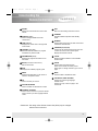
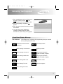
user's
4/9/01
3:24 PM
Page 1
SFT-503
SCI-503
Digital Satellite Receiver (FTA, CI)
Owner’s
Instructions
user's
4/9/01
3:24 PM
Page 2
General Information
Safety Precautions
This STB has been manufactured to meet international safety standards.
Please read the following safety precautions carefully before you handle the STB.
MAIN SUPPLY
Use only 90-250V AC 50/60Hz.
CABLE
Use standard certified cables to prevent any malfunction of
the STB.
LOCATION
Locate the STB indoor. Locate STB away from potential
hazards such as houseplants, lightning, raining and direct
sunlight.
CLEANING
1. Always disconnect the STB power cord from the wall socket
before cleaning it.
2. Use a light damp cloth(no solvents)to dust the STB.
OVERLOADING
Do not overload wall outlets, extension cords or adapters.
These can cause fire or electrical shock.
VENTILATION
1. NEVER block ventilation slots of STB.
2. NEVER stand the STB on soft furnishings or carpets.
3. Ensure that a free airflow is maintained around the STB.
4. Do not use or store the STB where it is exposed to direct
sunlight or near a heater.
5. NEVER stack other electronic equipment on top of the STB.
LIQUIDS
Keep liquids away from the STB.
SMALL OBJECTS
Coins or other small objects must be kept away from the STB.
They can fall through ventilation slots of the STB and cause
serious damage.
ATTACHMENTS
Do not use any attachments that are not recommended.
These may cause hazards or damage the equipment.
CONNECTION TO
THE SATELLITE
DISH LNB
Before connecting or disconnecting the cable from the satellite
dish to the STB, disconnect the STB from the mains supply.
FAILURE TO DO SO CAN DAMAGE THE LNB.
EARTHING
The LNB cable MUST BE EARTHED to the system earth for the
satellite dish. The earthing system must comply with SANBS061.
user's
4/9/01
3:24 PM
Page 3
General Information
LIGHTNING
1. The STB must remain connected at all times to the main
power supply and satellite dish.
2. However, Manufacture's instructions for safeguarding other
equipment connected to the STB, TV set, etc., must be
followed during lightning storms.
3. Ensure lightning protection devices for the terrestrial
antenna, mains, and LNB are installed.
SERVICING
1. Do not attempt to service this product yourself.
2. Refer all servicing to qualified service representatives.
Support & Copyright
For best satisfaction of SAMSUNG’s customer, we do our best for each product and services.
Also we will support our customer through our local sales, service network and electronic
server system of SAMSUNG.
Moreover, we maintain very close working relationships with our customers.
We take a highly disciplined engineering approach to product design, manufacture, testing, acceptance and to technical and maintenance support.
We conduct comprehensive testing of the units, provide complete documentation support
and deliver the highest quality, most consistent products on time, every time.
SAMSUNG supports you via its homepage with useful information and new software of
the STB.
When you have a question about this product, please refer the following homepage.
Homepage : http://stb.samsungcorp.com
To provide you the convenience of usage SAMSUNG has the right to make changes and
improvements to any of the products described in this manual and the manual of the
products without any notice in advance.
Copyright 2000. SAMSUNG CORPORATION. All rights reserved.
user's
4/9/01
3:24 PM
Page 4
Contents
Understanding the Remote Control Unit
1~2
Connecting Your Equipment
3
Front Panel
3
Rear Panel
4
Connection
5~6
Reference
7~8
Setting Up Your System
9
Menu Tree
9
Automatic Channel Search for a Satellite
10
Manual Channel Search for Transponder
10
NIT channel search
11
Basic Function
11 ~ 12
Menu Operation
13
Main Menu
13
Channel List
14
Program Guide
15
Channel Control
16
Edit Channel List
16
Edit Favorite TV/Radio Channels
17
Edit Lock Channel
18
Rename Channel
19
user's
4/9/01
3:24 PM
Page 5
Contents
Installation
19
DiSEqC Mode
20
Channel Search
21
Rename Satellite
21
Automatic Channel Search
22
Manual Channel Search
23
NIT Channel Search
24
Parental Lock
25
Receiver Lock
25
Change PIN Code
26
Factory Reset
26
Delete Whole Channel
26
System Setting
27
Utillity
28 ~ 29
Common Interface
30
Troubleshooting
31
Technical specifications
32 ~ 33
user's
4/9/01
3:24 PM
Page 6
Understanding the
Remote Control Unit
Remote Control Unit (RCU)
14 NUMERIC
STANDBY 13
SOUND 1
TIME 3
SUBTITLE(option) 2
7 EPG
4 TV/RADIO
5 INFORMATION
6 BACK
MENU 8
LEFT/RIGHT 19
PAGE UP/DOWN
OK 9
11 CHANNEL
UP/DOWN
10 VOLUME UP/DOWN
EXIT 12
FAVORITE 15
(F1,F2,F3,F4)
TV/SAT 16
SLEEP(option)
1
18 MUTE
17 PAUSE
TEXT (option)
user's
4/9/01
3:24 PM
Page 7
Understanding the
Remote Control Unit
1 SOUND
Selects the sound track list for the current
service.
2 SUBTITLE (RED)
Used to change satellite at channel
control menu.
3 TIME (GREEN)
Displays the current time on the right side
of the screen .
12 EXIT
Returns to the viewing mode from a menu.
13 STANDBY
Switches between Operation and Standby
mode.
14 NUMERIC
Used to select the service and enter the channel
information and PIN Code.
4 TV/RADIO (YELLOW)
Receiver switches between TV program
and Radio only receive mode.
15 FAVORITE (F1,F2,F3,F4)
Used to set the favorite service list of each user.
4 users can have his own favorite option.
Displays the Favorite channel.
5 INFORMATION (BLUE)
Displays the program information box on
the screen .
16 TV/SAT
Receiver switches between TV and Satellite
receive mode.
6 BACK (At channel control menu.)
Returns to the item.
17 PAUSE
Used to select the freeze function.
Press once to freeze the screen picture.
Press again or change channel to go to normal
again.
7 EPG
Displays the TV/Radio program guide.
8 MENU
Displays the Main Menu on the screen or
returns to the previous menu.
9 OK
Used to confirm your choice.
10 VOLUME UP/DOWN
Used to increase or decrease the volume.
18 MUTE
Used to enable or disable the audio.
19 LEFT/RIGHT, PAGE UP/DOWN
Used to move left or right highlight
marked Cursor.
Used to move up or down a page in the
channel list.
11 CHANNEL UP/DOWN
Used to tune to the next or previous channel.
Used to move up or down highlight marked
cursor.
Please note: The design of the Remote Control Unit (RCU) may be changed
without notice in advance.
2
user's
4/9/01
3:24 PM
Page 8
Connecting Your Equipment
Front Panel
1
3
2 3 4 5
6
7
1 STANDBY
Switches between Operation and Standby mode.
2 MENU
Displays the Main Menu on the screen or returns to the previous memu.
3 CLEAR
Returns to the viewing mode from a menu (in menu mode).
4 CH UP/DOWN
Use to tune to the next or previous channel.
Use to move up or down highlight marked Cursor.
5 VOL UP/DOWN
Use to increase or decrease the volume.
Use to move left or right highlight marked Cursor .
6 OK
Use to confirm your choice.
7 CAM Slots
2 Slots for Common Interface CAM (VIACCESS, IRDETO,
NAGRAVISION, CRYPTOWORKS, CONAX) with SmartCard
user's
4/9/01
3:24 PM
Page 9
Connecting Your Equipment
Rear Panel
1 2
3
4 5
6
8 7 9 10
11
1 ANT IN
Connect to TV ANT input
2 TV OUT
Connect to TV or VCR via a coaxial cable.
3 RS232
Connect to a PC for S/W upgrade.
4 VCR SCART
Connect this socket to that of VCR via scart cable.
(SFT-503E only)
5 TV SCART
Connect this socket to that of TV via scart cable.
(SFT-503E only)
6 0V / 12V
Connect 12V to an external 0V/12V switch.
7 VIDEO
Connect video to TV using RCA jack.
8 AUDIO
Connect audio R/L to TV or Audio Amp or System.
9 LOOP THROUGH
Connect to the other satellite receiver.
10 LNB
Connect to satellite antenna.
11 POWER
Power ON( ), OFF( )
4
user's
4/9/01
3:24 PM
Page 10
Connecting Your Equipment
Connection
There are several ways of connecting the STB to your existing Audio/TV system.
We recommend using one of the following connection cases for best results:
1. TV only
1. Connect one end of RCA/Cinch cable to the RCA/Cinch jack on the back of
the STB and the other end to a RCA/Cinch jack on your TV.
If your TV doesn’t have a RCA/Cinch jack, connect one end of RF cable to the
TV OUT on the back of the STB and the other end to a RF input jack on your TV.
2. Finally connect the coaxial cable from the LNB to the LNB IN jack on the STB.
(To RCA/Cinch on your TV)
(If your TV does’nt have
a RCA/Cinch Jack)
2. With Hi Fi System
Connect an RCA/Cinch stereo cable from the AUDIO L, R jacks on the back of
the STB to the LINE, AUX, SPARE OR EXTRA input jacks on your Hi Fi System.
5
user's
4/9/01
3:24 PM
Page 11
Connecting Your Equipment
Connection
3. TV with Terrestrial antenna
1. Connect one end of
RCA/Cinch cable to the
RCA/Cinch jack on the back
of the STB and the other end
to a RCA/Cinch jack on your
TV. If your TV doesn’t have a
RCA/Cinch jack, connect one
end of RF cable to the TV
OUT on the back of the STB
and the other end to a RF input
jack on your TV.
(To RCA/Cinch on your TV)
(If your TV doesn’t
RCA / Cinch Jack)
2. Connect one end of RF cable to the ANT IN on the back of the STB and the other
end to a terrestrial antenna connection or the jack for public antenna on the wall.
3. Finally connect the coaxial cable from the LNB to the LNB IN jack on the STB.
4. TV with Motorised System (DiSEqC 1.2)
1. Connect one end of
RCA/Cinch cable to the
RCA/Cinch jack on the back
of the STB and the other end
to a RCA/Cinch jack on your
TV. If your TV doesn’t have a
RCA/Cinch jack, connect one
end of RF cable to the
TV OUT on the back of the STB
and the other end to a RF input
jack on your TV.
(To RCA/Cinch on your TV)
(If your TV doesn’t
RCA / Cinch Jack)
2. Connect one end of your coaxial cable to the LNB IN connector on the STB
and the other end to the REC or Receiver connector on the DiSEqC 1.2 motor.
3. Connect the coaxial cable from the LNB to the LNB connector on the
DiSEqC 1.2 motor.
6
user's
4/9/01
3:24 PM
Page 12
Connecting Your Equipment
Reference
DiSEqC 1.0 Connection
All our receivers are designed to be DiSEqC 1.0 and DiSEqC 1.2 compatible.
This allows multiple antennas to be connected to the STB at the same time.
If you have two or more fixed antennas or LNBs then we recommend you use a
DiSEqC 1.0 switch.
Connect the coaxial cable from the first LNB to the LNB 1 or LNB A input connector
of the DiSEqC switch.
Do the same for any other LNBs that you have.
Connect one end of a coaxial cable to the RF output connector of the
DiSEqC switch, connect the other end to the LNB IN socket on the STB.
DiSEqC 1.2 Connection
Please refer to page 20.
To the digital receiver, you can connect either a single satellite antenna directly or
LNB of multi-feed equipment.
Upgrade via personal computer
To maintain the STB up-to-date, it will be possible
to upgrade the software of the STB via STB and
personal computer.
New versions of the software may
include new or improved functions for the latest one.
If you want to download and upgrade the software via
personal computer, visit our homepage
(http : //stb.samsungcorp.com) to get more information
and the new software.
1. Go to the Homepage and check the latest software to upgrade.
2. Download the latest software of your STB model to your PC directory.
3. Connect a cable between the COM1 port of your PC and RS232 port of the STB.
4. After that connection, make sure the STB is in STANDBY status.
(Front panel displays
)
5. Then, run the downloaded file by double click it on your PC.
6. Then, power on STB by pressing the power button of front panel or by pressing the
power button of RCU
7
user's
4/9/01
3:24 PM
Page 13
Connecting Your Equipment
7. Then, upgrading starts, the PC will shows the
progress in window, and the
and
appears on the front LED of the STB.
8. When the upgrading is completed,
appears.
9. Then, you have to power off and on for running
new software.
10. You can check correct upgrading by
comparing software version in system
information of system setting menu (page27).
Front Panel Display Message
KEY & DISPLAY
The message of the 7-segment LED (Light-Emitting Diode) on the STB
and keys are explained as below.
Indicates the memo has been
memorized.
Download procedure.
When operating manual search.
Upgrade procedure.
When operating auto search.
When program download /
upgrade is normally complete.
When selecting CVBS mode.
When program download /
upgrade is normally complete.
When selecting RGB mode.
Download in master.
When selecting TV mode.
When error happens.
When selecting SAT mode.
8
user's
4/9/01
3:24 PM
Page 14
Setting Up Your System
Menu Tree
9
user's
4/9/01
3:24 PM
Page 15
Setting Up Your System
Automatic Channel Search for a Satellite
You can automatically detect and save all TV, Radio channels of a Satellite as follows:
System Connection
• Connect STB to all peripheral devices.
➞
Power On
• Turn on the power of STB and other devices.
➞
Main Menu/Installation
➞
Channel search / Auto
➞
Channel List
➞
Favorite Channel List
• Enter your PIN Code. (Initial PIN Code is “0000”)
• Select Automatic Search in Search Mode.
• Select the satellite which you want to search by
pressing the Red button.
• Press
, and STB will automatically search all
TV/Radio channels from a satellite and save them
into Channel List.
• If you select Channel List in Menu Mode, you can
see all channels that you saved into channel list.
• Select Menu/Channel Control/Edit Favorite Channel
• Select a channel that you want to add into the
favorite channel list.
Manual Channel Search for a Transponder
You can automatically search and save all TV, Radio channels of a transponder as follows.
Main Menu/Installation
➞
Channel Search / Manual
• Enter your PIN Code.
• Select Manual Search in Search Mode.
• Select the satellite which you want to search.
• Select the transponder from transponder list which
you want to search.
• If you cannot find it from transponder list, you should
insert all the transponder information
(i.e., Frequency, Symbol Rate, Polarity and FEC).
• Press
button and STB will automatically search
for all channels contained in the selected transponder.
10
user's
4/9/01
3:24 PM
Page 16
Setting Up Your System
NIT Channel Search
You can automatically detect and save all TV, Radio channels of a satellite as follows:
Main Menu/Installation
➞
Channel Search / NIT
• Enter your PIN code.
• Select NIT Search in Search Mode.
• Select the NIT of satellite which you want to search.
• Press
, and STB will automatically search all
TV/Radio channels using NIT and save them into
channel List.
N o t e : If NIT information is not properly broadcasted, all TP or channels may not be saved.
Basic Function
Channel (Service) Change
1. Use the numeric buttons (0~9) on the remote control to select the Channel No. you want
2. Press the
button on the remote control and select the channel you want from the
Channel List.
3. Use the CH
buttons on the remote control to select the channel you want.
4. Use the INFO (BLUE BUTTON) button on the remote control to view information of that
channel.
11
user's
4/9/01
3:24 PM
Page 17
Setting Up Your System
Volume Control / Mute
Use the VOL button to control the volume.
When the volume is adjusted under the MUTE button holding pressed, the Mute
feature cannot be cancelled. Press the MUTE button once again to cancel.
Sound Track
The Audio control menu appears when the Sound button on the remote control is
pressed on the channel having different types of sounds.
Use the
buttons on the remote control to select the sound you want.
Use the
buttons on the remote control to select the sound type
(Stereo, mono, left, right).
12
user's
4/9/01
3:24 PM
Page 18
Menu Operation
Main Menu
1. Turn on TV and your STB, after you have connected all peripheral devices to it.
2. Press the Menu button of the RCU. You will see the "Main Menu" on the TV screen as follow:
3. You can move into the desired submenu using
4. Press
buttons.
to confirm your selection.
5. Press the
button to return to previous menu. Or press the
System completely.
button to quit the Menu
Main menu shows the following information.
13
Channel List
Shows the whole channel list stored in STB.
Program Guide
Shows the information of Now, Next and Weekly Programs.
Channel Control
Edit Channel List/Favorite Channel/Lock Channel/Rename
Channel.
Installation
Allows you to configure Antenna, search channels
Automatically/Manually and Rename satellite.
System Setting
Sets Video Output mode, RF Channel, RF Mode, Screen
Type, Banner Time, Time Adjust, Menu Language and
System Information.
Utility
BIO Rhythm, Calendar, Othello Game, Snake Game, Write
Memo and Read Memo.
Common Interface
2 Slots for Common Interface CAM with Smart Card.
Demonstration
Shows the usage of STB Functions.
user's
4/9/01
3:24 PM
Page 19
Menu Operation
Channel List
TV and Radio Channel List
This menu helps you to easily select the channel that you want to watch.
The channel list can be constructed independently for each Satellite, Channel Control, TV or Radio.
1. Select "Channel List" in"Main Menu". Then you will get a "Channel List" as follows.
You can get the information of channel number, channel name, and the program is
scrambled(S).
2. To watch a specific channel, first select it by pressing the
button and
button.
Then press
button on the RCU. The selected channel will appear on the right
display window.
=
You can also move into a specific channel using numeric button on the RCU.
=
When you press Red button on the RCU, you can see and control the Channel List by
each satellite.
=
When you press Green button on the RCU, you can see and control the Channel List by each
channel control.
=
When you press Yellow button on the RCU, you can automatically select TV and Radio
Channel List.
=
When you press F1~F4 on the RCU, you can see the Favorite Channel List.
14
user's
4/9/01
3:24 PM
Page 20
Menu Operation
Program Guide
Your STB has an Electronic Program Guide(EPG) to help you navigate programs through all the
possible viewing options. The TV Guide supplies information such as program listings and starting
and ending times for all available programs.
=
Select Program Guide in Main Menu or press the EPG button of RCU and the Program
Guide screen will be displayed.
1. Now / Next EPG
=
Shows the titles of the Now and Next Program on different channels.
=
The information is only available from the transponder in which the channel you are
watching belongs.
=
The information may include: current time, name of the Now and Next Program, the starting
and ending time of the Now/Next Program, progress bar of the program and on-screen display
window.
=
Program information will be available only when it is included in the transmission.
=
When you press F1 on the RCU, you can alternatively select Now or Next Program Guide.
=
When you press
on the RCU, you can alternatively select TV or Radio Channel Guide.
=
When you press
window
button, it display the extended event description text in the right side of the
2. Weekly EPG
=
Shows the information of program that will be played for a week.
=
When you press
=
=
on the RCU, you can alternatively select Now or Weekly EPG.
To see more information about the program you want on the weekly EPG, move the highlighted
channel by pressing
and then press the
button.
Press the Blue button to select the date you want.
N o t e : If the button is not pressed hard on Channels (Programs), the BLUE button doesn’t operate.
To see detailed information about the event you want when a channel has been selected,
press the
button on the appropriate event.
15
user's
4/9/01
3:24 PM
Page 21
Menu Operation
Channel Control
You can control channels on various channel lists-Delete a channel, Move channel's position,
construct Favorite Channel List, Lock a channel and change the name of a channel.
Select "Channel Control" in "Main Menu". Then the following "Channel Control" screen will
be displayed.
=
1. Edit Channel List
You can delete a channel, delete all channel list and move channel's position from the channel list.
1. Delete a Channel
=
Use the
buttons to select the channel that you want to delete from
the channel list.
Press F2 and the selected channel will disappear from the channel list.
2. Delete All Channel
=
If you want to delete all channel from the channel list, press F3.
3. Move the position of a channel
=
Use the
buttons to select the channel that you want to move its position and
press the F1 button.
=
Move it to the position where you want to place it using the channel button (
=
Press the
changed.
).
button to confirm. Note that the channel number of the channel should be
N o t e : Press the
button or
button to save the state of data movement
before pressing the
button.
=
Press the
button to return to the previous menu. Press the
and turn to the viewing mode.
button to exit this menu
16
user's
4/9/01
3:24 PM
Page 22
Menu Operation
2. Edit Favorite TV/Radio Channels
You can edit the Favorite Channel List, which facilitates you to easily find your favorite channel
from the Channel List.
=
=
=
=
=
=
=
17
In "Channel Control"menu, select "Edit Favorite Channel". Then the following “Edit Favorite
Channel” screen will be displayed.
You can choose TV or Radio Channels in an alternative way by pressing
button on the RCU.
Use the
buttons, to select a channel that you want to add into favorite channel list.
Press (F1~F4) and the selected channel will be added to each (F1~F4) group of the favorite
channel list.
The Favorite Channel List can be sectioned into four categories (F1~F4).
And one channel can be multiple selected from F1 to F4.
Press the Green button to see the Favorite Channel List (F1~F4).
You can also delete a channel from the favorite channel list.
Select a channel that you want to delete from the favorite channel list. Press F1~F4 of the same
number is marked at the right side of the channel name on the Edit Favorite Channel List.
On the other hand, the favorite channel is displayed with the symbol of “lock” on the
Information screen.
Press the
button to return to the previous menu.
user's
4/9/01
3:24 PM
Page 23
Menu Operation
3. Edit Lock Channel
In "Channel Control "Menu, select "Edit Lock Channel". Then the following “Edit Lock Channel”
screen will be displayed.
You should enter your PIN Code in order to modify or watch the previously locked channel.
=
Press
button to select the program you want to lock or unlock. Press the F1 button
to have the channel locked so that the others who do not know the PIN Code can not watch
the program. Also you can use
to select either TV channel list or Radio channel list.
=
Once the program is locked, every time you try to watch the program, you will be asked to
enter PIN code. The locked channel number is marked at the right side of the channel name on
the Edit Lock Channel List. On the other hand, the locked channel is displayed with the symbol
of “lock” on the Information screen.
=
Press the
button to return to the previous menu. Press the
and return to the viewing mode.
button to exit this menu
N o t e : The Parental Lock on the Install menu must be switched ON so that the Channel Lock
can work. When the Parental Lock is set OFF, even though the LOCK is set, anyone
can watch the Parental Lock channel.
18
user's
4/9/01
3:24 PM
Page 24
Menu Operation
4. Rename Channel
In "Channel Control"menu, select "Rename Channel" and then the following Rename channel
screen pops up.
=
=
=
Use the
buttons to select the channel that you want to change
the name of a channel from the channel list and press F1 button.
Then following “Rename channel” menu and keyboard screen will be displayed.
Use the
and
buttons to key in the new channel name.
The F1 button: save the new channel name
The F2 button: display the other character list.
The F3 button: erase the character currently selected.
N o t e : The maximum length of the channel name is allowed up to 16 characters.
You can directly input the number by yourself pushing the numeric buttons in the Remote
Control Unit.
Installation
"Installation Menu" helps you to setup a variety of parameters necessary for receiving signal and
managing the channel information. To avoid loss of service, it is important to understand the
following table before you make changes.
=
19
Select "Installation" menu in "Main
Menu". Before the installation menu,
it requires PIN Code input for security
check. Then the following “Installation”
screen will be displayed.
user's
4/9/01
3:24 PM
Page 25
Menu Operation
1. DiSEqC Mode
Supports DiSEqC 1.0 and 1.2.
1.1 DiSEqC 1.0
=
2, 4, or 8 port can be selected for DiSEqC
switch box. You can select and
use the appropriate port for your DiSEqC
switch box.
=
Use the
buttons to select 2SW,
4SW, or 8SW in the Installation DISEqC
Mode. And then press the
button.
=
=
Connect the satellite LNB line to the
appropriate port. To use the port, press the
buttons to set the satellite you want.
Any unused port must be set OFF.
Press the
button or
button to save the set data.
1.2 DiSEqC 1.2
You can use the DiSEqC 1.2 motorized system,
if it exists.
Setting
=
Use the
buttons to select the
Motor from the Installation DiSEqC
Mode. And then press the
button.
=
You can set the Position within the numbers
0 ~ 59 (60). Select the number you want.
=
Select the name of Satellite.
=
Select the number of TP which has a good signal from the TP List.
=
Use the FINE DRIVE, INSTALLER to run the MOTOR.
And then move the antenna to the appropriate satellite.
=
Press the
button in the Save position to save the set data.
Searching
=
Use the
buttons to search for the Position and find the name of
satellite you want.
=
Press the
=
Select the channel you want to watch after changing the satellite from the
Channel List. Then, the antenna automatically moves to the set position.
button in the Go to Position to move to the set position.
20
user's
4/9/01
3:24 PM
Page 26
General Information
2. Channel Search
Search Mode
L.O. Freq.(MHz)
Auto / Manual / NIT
LNB Power
Depending on the user's antenna LNB, you can supply either
LNB power by setting "ON" or not by setting "OFF".
22KHz
OV/12V Antenna
Switch
You can select the predefined L.O Frequency by pressing
Left/Right keys or manually enter a specific frequency in
MHz unit by pressing numeric buttons.
Depending on the user's antenna switch box or LNB, you can
supply either 22KHz by setting "ON" or not by setting "OFF".
Depending on the user's antenna switch box, you can pick up
either 12V by Setting "ON" or 0V by setting "OFF".
Tone Burst
Depending on the user's antenna switch box, you can select
one of "SA", "SB" and "OFF".
Scramble
NO/OFF, if it set "ON", all channel can be scan including
scrambled channel.
Please contact the installer of your satellite dish if
you do not know the correct setting value of each
parameter listed in the above table.
3. Rename Satellite
=
Use the Red buttons to select the satellite that you
want to change the name of a satellite
from the satellite list and press F1 button.
=
Use the
and
buttons to key in the
new satellite name.
The F1 button: save the new satellite name,
The F2 button: display the other charaster list.
The F3 button: erase the character currently selected.
N O T E : The maximum length of the satellite name
is allowed up to 14 characters.
Press F1 in the Channel Search to
change the name of satellite.
You can directly input the number by yourself pushing the numeric buttons in the Remote
Control Unit.
21
user's
4/9/01
3:24 PM
Page 27
Menu Operation
4. Automatic Channel Search
Automatic Channel Search helps you to automatically load the channel information of all
transponders contained in a selected satellite.
=
=
Select "Channel Search" in "Installation Menu". Then the following will be displayed.
Use the RED button to select the satellite you want to find.
=
Select the Automatic search mode from "Search Mode" field using
button.
=
Search Mode, Set L.O. Freq, LNB Power, 22KHz, 0V/12V, Tone Burst and Scramble fields to
the appropriate value Using
button at each field.
=
Press
to start the "Automatic Channel Search" procedure. You can see the progressive
status of channel searching.
=
Use the
=
When the Channel Search is complete, the result will be save the data and display the
first channel of the searched ones.
=
Press the
=
Please note that the "Automatic Channel Search" procedure may take a few minutes.
button to stop Channel Search.
button to return to the previous menu.
22
user's
4/9/01
3:24 PM
Page 28
Menu Operation
5. Manual Channel Search
It will be more convenient to use "Manual Channel Search" procedure when you want to search
channel for a specified transponder offered from the satellite. As in Automatic Channel Search,
Manual Channel Search also searches all channels broadcasted over a specific
transponder using its predefined information. You can add a new transponder if you cannot
find it on the predefined transponder list.
23
=
Select "Channel Search" in "Installation Menu"and the following screen will be displayed.
=
Select the Manual Search Mode from "Search Mode" field using the
=
Press the
=
If you cannot find the desired transponder from the transponder list, you can add it by inputting
appropriate parameter values for a new transponder in the corresponding item of numeric
number field.
=
When you want to change the parameter of an existing transponder, select the parameter
using the volume button(
) and change its value.
(Frequency, Symbol Rate, FEC, Polarity)
=
Press the
=
You can also search a channel of the specified transponder by specifying Video PID,
Audio PID and PCR PID.
=
Enter PIDs of Video, Audio and PCR ( the value is decimal )
=
Press the
=
Then the result will be save the data.
=
Press the
button to return to the previous menu. Press the
and return to the viewing mode.
=
Press F1 to delete all TPs one by one except the first TP and the last TP(add TP) of the current
satellite.
button.
button .
button to start the manual searching for the selected transponder.
button.
button to exit this menu
user's
4/9/01
3:24 PM
Page 29
General Information
6. NIT Channel Search
NIT Channel Search helps you to automatically load the channel information of all transponders
contained in a selected satellite.
=
=
Select "Channel Search" in "Installation Menu". Then the following will be displayed.
Use the RED button to select the satellite you want to find.
=
Select the NIT search mode from "Search Mode" field using
button.
=
Seach Mode, Set L.O. Freq, LNB Power, 22KHz, 0V/12V, Tone Burst and Scramble fields
to the appropriate value Using
button at each field.
=
Press
to start the "NIT Channel Search" procedure. You can see the progressive
status of channel searching.
=
Use the
button to stop Channel Search.
=
When the Channel Search is complete, the result will be save the data and display the
first channel of the searched ones.
=
Press the
button to return to the previous menu.
=
Please note that the "NIT Channel Search" procedure may take a few minutes.
24
user's
4/9/01
3:24 PM
Page 30
Menu Operation
7. Parental Lock
This function prevents children or unauthorized persons from watching programs.
=
Select "Parental Lock" from the "Installation Menu".
=
After the Parental is locked, whenever you watch the locked channel, you should enter the
PIN Code.
N o t e : When the Parental Lock is set OFF, you can watch the Lock Channel without
the entry of PIN Code.
8. Receiver Lock
To lock the receiver, select "Receiver Lock" in the "Installation menu" and change it to "On"
mode using
button.
Now the receiver is locked. Whenever you try to start STB, the following screen appears and
you will be asked to enter your PIN Code.
25
user's
4/9/01
3:24 PM
Page 31
Menu Operation
9. Change PIN Code
You can change your PIN code from factory default value "0000" as follows: Select "Change
PIN Code" in the "Installation" menu.
=
Then you will be asked for a new PIN Code. Once you enter a new PIN Code, the system
will ask you to enter it again to confirm.
=
After you enter a new PIN Code twice, the PIN Code has been changed. If you forgot
the PIN Code, you have to contact the distributor to recover it.
10. Factory Reset
All data you are using will be deleted and the default data will be loaded.
=
If you select “Factory Reset”, it asks your confirmation.
=
If you press “RED” button, then all data will be replace by factory setting.
=
If you don’t want to reset, press “Menu” or “Exit” to exit this menu.
11. Delete Whole Channel
The whole channel data of satellite will be deleted.
=
If you select “Delete whole channel”, it asks your confirmation.
=
If you press “RED” button, then all channel data of satellite will be deleted.
=
If you don’t want to delete, press “Menu” or “Exit” to exit this menu.
26
user's
4/9/01
3:24 PM
Page 32
Menu Operation
System Setting
This menu helps you to set up Video output mode, RF channel, RF mode, Screen type, Banner
Display Time, Time Adjust, Menu Language and System Information parameters related with RF
modulator.
=
27
Select "System Setting" in the "Main Menu". The following submenu will show up on
your TV.
Video output
Selects video output mode-RGB or CVBS
RF Channel
Select or change RF channel number when STB is connected
to TV by RF jack.( 21CH~69CH) Default : 40CH
RF mode
In the above case, you can choose PAL K, PAL G or PAL I.
Screen Type
You can choose either 4:3 or 16:9 according to the TV type.
Banner Time
You can set the display duration of information box displayed
on the Screen. The time ranges from 1 to 20 seconds.
Time Adjust
Adjust the current time from default time
(default time is based on Time Description Table of the current
service).
Menu Language
You can select the menu language.
System Information
Displays the system information : Model name, H/W version,
S/W version.
=
Press the
button to return to the previous menu.
=
Press the
button to exit this menu and return to the viewing mode.
user's
4/9/01
3:24 PM
Page 33
Menu Operation
Utility (Depending on model)
This STB supports additional functions such as Bio Rhythm, Calendar, Games, Write Memo and
Read Memo.
Bio Rhythm
buttons to adjust your birth year and date to see your current Bio Rhythm status.
=
By press "OK", you can see your Bio Rhythm.
=
The Bio Rhythm screen shows your monthly
Bio Rhythm.
=
The white column line shows the position of
today.
Calendar
F1: Previous Year
F2: Next Year
F3: Previous Month
F4: Next Month
28
user's
4/9/01
3:24 PM
Page 34
Menu Operation
Othello Game / Snake Game
Write Memo
Use the
and
buttons, write your message.
F1: Save your message
F2: Other character
F3: Erase
N o t e : You can directly input the number by
yourself pushing the numeric buttons
in the Remote Control Unit.
Read Memo
The latest message is displayed.
: Delete memo
: Exits to the current state of storage of
memo.
When memo is saved, the message “
” appears
on the front LED.
The message “
” appears on the LED when the
STB is powered ON. By the appearance of this message, you can notice the memo has been saved.
29
user's
4/9/01
3:24 PM
Page 35
Menu Operation
Common Interface
This receiver is equipped with two PCM-CIA
slots, which enables the use of two CI CAMs
(Viaccess or Irdeto etc...).
When a Comon Interface CAM is inserted inside
the PCM-CIA slot, the system detects the type
of the CAM automatically and display in the
main menu.
On choosing the menu, you will be able to access
the different options available with the type of the
CAM like authorizations, pre-booking, package
details etc.
You can see the Common Interface CAM’s name
which has been inserted.
Inserting Common Interface CAM and Smartcard
This receiver supports Common Interface CAMs under DVB specification.
The CI CAMs include a built-in Smartcard reader.
1. Insert the Smartcard into the CAM gently with the gold colored chip upwards.
2. Slide in the CAM gently inside the slot so that it sits in the socket tightly.
3. Close the door.
=
To remove the CAM push the button provided by the side of the CAM slot.
The CAM will be ejected from the socket.
30
user's
4/9/01
3:24 PM
Page 36
Troubleshooting
Problem
Solution
Something wrong with STB
Does not display any
message on the front panel
or STB has no power.
Check the main power cord and check that it is plugged
into a suitable power outlet.
No Picture
Ensure that the STB is switched on (see above).
Check whether STB is in Standby mode.
Check the video output port (VIDEO or RF OUT) is
firmly connected to the TV or VCR.
Check that you have selected the correct channel or
Video Input on your TV.
Check the brightness level of the TV.
See “No Picture” above.
Poor picture quality
Check the signal level, if this is low then try to
adjust the alignment of your dish.
See “No Picture” above.
No Sound
Check the volume level of the TV and STB.
Check the Mute status of the TV and STB.
Remote Control does not operate
Point remote control directly towards the STB.
Check and replace batteries.
About On-Screen Error Message
No or Bad Signal
Check the LNB - replace LNB if necessary.
Check the cable from the LNB.
Check the position of the dish
- realign dish if necessary.
If you are using a DiSEqC 1.0 switch, check that you
have connected the LNBs to the correct connections on
the switch.
Check the “Signal Strength” and the “Signal Quality” in
the channel list or channel search menu
31
user's
4/9/01
3:24 PM
Page 37
Technical Specifications
Tuner & Channel
Input Connector
Frequency Range
Input Impedance
Signal Level
IF Frequency
IF Band width
LNB Power & Polarization
:
:
:
:
:
:
:
22 KHz Tone
:
DiSEqC Control
Demodulation
Input Symbol Rate
FEC Decoder
:
:
:
:
F-type, IEC 169-24, Female
950 MHz to 2150 MHz
75Ohm unbalanced
-25 to -65dBm
480 MHz
36 MHz
Vertical : +13V, Horizontal : +18V
Current : 500mA Max Overload
protection
Frequency : 22 4KHz
Amplitude : 0.6 0.2V
Version 1.0 / 1.2 Compatible
QPSK
1-45 Ms/s
Convolutional Code Rate 1/2, 2/3, 3/4,
5/6 and 7/8 with Constraint Length K=7
MPEG Transport Stream A/V Decoding
Transport Stream
Profile Level
Input Rate
Aspect Ratio
Video Resolution
Audio Decoding
Audio Mode
Sampling
: MPEG-2 ISO/IEC 13818
Transport stream Specification
: MPEG-2 MP@ML
: Max 90 Mbit/s
: 4:3, 16:9
: 720 x 576
: MPEG / MusiCam Layer I & II
: Single channel / Dual channel / Joint
stereo
: 32, 44.1 and 48KHz
Memory/Processor
Main Processor
Flash Memory
Program DRAM
MPEG DRAM
Graphic DRAM
:
:
:
:
:
New-TMIPS R3930 (81MHz)
1Mbyte (Asynchronous)
2Mbyte
2Mbyte
2Mbyte
32
user's
4/9/01
3:24 PM
Page 38
Technical Specifications
Common Interface
Module Type
Available CAM
: PCMCIA TYPE II x 2
: VIACCESS, IRDETO, NAGRAVISION,
CRYPTOWORKS, CONAX.
A / V & Data In / Out
VIDEO (CVBS)
VIDEO (RGB)
AUDIO R/L
RS232C
: RCA/Cinch , Scart (SFT - 503E only)
Video Output (CVBS)
: Scart (SFT-503E only)
: RCA/Cinch, Scart (SFT-503E only)
Volume and Mute Control (Resolution :20bit DAC,
max 2Vrms)
: Transfer rate 115,200 bps
9 pin D-sub Type
RF-Modulator
RF-Connector
Frequency
Output Channel
TV Standard
Preset Channel
:
:
:
:
:
75Ohm, IEC 169-2, Male / Female
470MHz to 860MHz
CH21-69 for the Remodulator
PAL K/G/I selectable by Menu
CH36(or TBD).
Software changeable by Menu
:
:
:
:
:
90 to 250V AC, 50/60 Hz
SMPS (Switch Mode Power Supply)
Max. 30W
8W
Separate internal fuse.
The input shall have lightning Protection
:
:
:
:
:
340 x 240 x 65 mm
2 Kg
0°C to +45°C
-10°C to +70°C
5% ~ 95% RH (Non-Condensing)
Power Supply
Input Voltage
Type
Power Consumption
Standby Power
Protection
Physical Specification
Size (W x H x D)
Weight (Net)
Operating Temp
Storage Temp
Storage Humidity
33
user's
4/9/01
Memo
3:24 PM
Page 39
user's
4/9/01
3:24 PM
Page 40
General Information
SAMSUNG
CORPORATION
C. P. O. BOX 1144,
Seoul. Korea