1
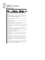
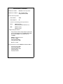
Owner’s Manual
SR835 Crossover
A Harman International Company
Warning
For your protection, please read the following:
Water and Moisture: Appliances should not be used near water
(e.g. near a bathtub, washbowl, kitchen sink, laundry tub, in a wet
basement, or near a swimming pool, etc.) Care should be taken so
that objects do not fall and liquids are not spilled into the enclosure
through openings.
These symbols are internationally accepted symbols that warn of potential
hazards with electrical products.The lightning flash means that there are
dangerous voltages present within the unit.The exclamation point indicates
that it is necessary for the user to refer to the owners manual.
These symbols warn that there are no user serviceable parts inside the unit.
Do not open the unit. Do not attempt to service the unit yourself. Refer all
servicing to qualified personnel. Opening the chassis for any reason will void
the manufacturer’s warranty. Do not get the unit wet. If liquid is spilled on
the unit, shut it off immediately and take it to a dealer for service.
Disconnect the unit during storms to prevent damage.
U.K. Mains Plug Warning
A molded mains plug that has been cut off from the cord is unsafe.
Discard the mains plug at a suitable facility. Never under any circumstances should you insert a damaged or cut mains plug into a 13
amp power socket. Do not use the mains plug without the fuse cover
in place. Replacement fuse covers can be obtained from your local retailer. Replacement fuses are 13 amps and MUST be ASTA approved to
BS1362.
Power Sources: The appliance should be connected to a power
supply only of the type described in the operating instructions or as
marked on the appliance.
Grounding or Polarization: Precautions should be taken so that
the grounding or polarization means of an appliance is not defeated.
Power Cord Protection: Power supply cords should be routed so
that they are not likely to be walked on or pinched by items placed
upon or against them, paying particular attention to cords at plugs,
convenience receptacles, and the point where they exit from the
appliance.
Servicing: To reduce the risk of fire or electrical shock, the user
should not attempt to service the appliance beyond that described in
the operating instructions. All other servicing should be referred to
qualified service personnel.
For units equipped with externally accessible fuse receptacle: Replace fuse with same type and rating only.
Safety Instructions
Electromagnetic Compatibility
Notice for customers if your unit is equipped with a power cord.
Operation is subject to the following conditions:
•This device may not cause harmful interference.
•This device must accept any interference received, including
interference that may cause undesired operation.
•Use only shielded interconnecting cables.
•Operation of this unit within significant electromagnetic fields
should be avoided.
Warning:This appliance must be earthed.
The cores in the mains lead are colored in accordance with the following
code:
Green and Yellow - Earth Blue - Neutral
Brown - Live
As colors of the cores in the mains lead of this appliance may not correspond with the colored markings identifying the terminals in your plug, proceed as follows:
•The core which is colored green and yellow must be connected to the
terminal in the plug marked with the letter E, or with the earth symbol, or colored green, or green and yellow.
•The core which is colored blue must be connected to the terminal
marked N, or colored black.
•The core which is colored brown must be connected to the terminal
marked L, or colored red.
This equipment may require the use of a different line cord, attachment
plug, or both, depending on the available power source at installation. If the
attachment plug needs to be changed, refer servicing to qualified service
personnel who should refer to the table below.The green/yellow wire shall
be connected directly to the units chassis.
CONDUCTOR
L
LIVE
WIRE COLOR
Normal
Alt
BROWN
BLACK
N
NEUTRAL
BLUE
WHITE
E
EARTH GND
GREEN/YEL
GREEN
Warning: If the ground plug is defeated, certain fault conditions in the unit
or in the system to which it is connected can result in full line voltage
between chassis and earth ground. Severe injury or death can then result if
the chassis and earth ground are touched simultaneously.
SR835 Crossover
INTRODUCTION
Congratulations, and thank you for your purchase of the DOD SR835 Crossover.
The SR835 is a high quality sound reinforcement tool capable of providing your
PA or sound reinforcement system with speaker protection and the increased
clarity and efficiency that results when bi-amping, or tri-amping.
So what is bi-amping, and tri-amping? A bi-amped system means you are using
two power amps to drive separate ranges of frequencies.The crossover is doing
a two way split, separating the high frequencies from the low frequencies and
directing the two ranges to different outputs. One amp receives the low frequencies, and powers your bass speakers.The other power amp receives the high
frequencies and powering the horns, or high frequency speakers.Tri-amping uses
three power amps because the crossover is separating the lows, mids, and highs
from each other.
The SR835 is capable of 2 way splits(bi-amp) in stereo, and three way splits (triamp) in mono.The SR835 uses Butterworth state variable filters providing an 18
dB per octave slope for the selected crossover frequency. This means that if you
have selected the crossover frequency to be 500Hz for instance, the signal coming out of the the low frequency output will loose 18 dB of signal for every
octave above 500 Hz. Likewise, the high frequency output will lose 18 dB of signal for every octave below 500 Hz.
This Owner’s Manual is your guide to understanding how to get the most out of
the SR835. Please read it carefully and familiarize yourself with the controls on
the SR835. By doing so, you will be assured to increase the over all efficiency of
your system for years to come.
Your SR835 was carefully assembled and packaged at the factory. Before continuing any further, please make sure the following items have been included:
1 SR835
1 Owners Manual
1 Warranty Card
1 Detachable Power Cord
Please take a moment to fill out the warranty card. It is your safe guard in the
unlikely event that your unit requires servicing. Please save all packing materials
and use these materials to return the product if servicing is required.
1
2
SR835 Crossover
FRONT PANEL
1
2
3
4
5
6
7
8
9
10
11
12
1. Power Switch - Used to engage or disengage the power to the SR835.
2. Mono/Stereo Switch - This switch configures the SR835 as two independent channels of 2 way splits, or one channel with a 3 way split.When the switch
is in and the LED is lit, the SR835 is in Mono mode.
3. Gain - This is the input level for Channel 1 in Stereo mode, and is the master input level in Mono mode.
4. Low Level - This knob controls the volume for the low frequency output in
both Stereo and Mono modes.
5. High Level - This knob controls the volume for the Channel 1 high frequency output in Stereo mode, and has no function in Mono mode.
6. Frequency - This knob sets the crossover frequency separating the lows
from the mids in Mono mode, and the lows from the highs for Channel 1 in
Stereo mode.
7. Range Switch - When depressed, this switch will multiply the selected
crossover frequency by 10.The LED will light indicating that the markings on the
Frequency knob (6) should be multiplied by 10.
8. Channel 2 Gain - This is the input level for Channel 2 in Stereo mode. In
Mono mode this knob has no function.
9. Low/Mid Level - This knob controls the volume for the Channel 2 low frequency output in Stereo mode, and the mid-range frequency output volume in
Mono mode.
10. High Level - This knob controls the volume for the Channel 2 high frequency output in Stereo mode, and the high frequency output in Mono mode.
11. Frequency - This knob sets the crossover frequency separating the mids
from the highs in Mono mode, and the lows from the highs for Channel 2 in
Stereo mode.
12. Range Switch - When depressed, this switch will multiply the selected
crossover frequency by 10.The LED will light indicating that the markings on the
Frequency knob (11) should be multiplied by 10.
SR835 Crossover
REAR PANEL
WARNING: TO REDUCE THE RISK OF FIRE OR ELECTRIC SHOCK
DO NOT EXPOSE THIS EQUIPMENT TO RAIN OR MOISTURE.
HIGH BAL.
HIGH UNBAL.
LOW BAL.
LOW UNBAL.
STEREO
INPUT
LOW SUM OUT
HIGH BAL.
HIGH UNBAL.
LOW BAL.
LOW UNBAL.
CHANNEL 2
MONO
HIGH BAL.
HIGH UNBAL.
MID BAL.
MID UNBAL.
1
2
3
4
120 V
100 V
WARNING: SHOCK HAZARD-DO NOT OPEN
AVIS: RISQUE DE CHOC ÉLECTRIQUE-NE PAS OUVRIR
CAUTION: TO REDUCE THE RISK OF ELECTRIC SHOCK DO NOT REMOVE BACK. NO USER
SERVICEABLE PARTS INSIDE. REFER SERVICING TO QUALIFIED SERVICE PERSONNEL.
STEREO
60 Hz
OR
50 Hz
INPUT
CHANNEL 1
MONO
5
6
7
8
LOW BAL.
LOW UNBAL.
9
10
DOD Professional Products
Sandy,Utah U.S.A.
11
18 WATTS
12
1. High Bal - This is a TRS balanced output for the high frequencies in both
Mono mode and Channel 2 in Stereo mode.
2. High Unbal - This is an unbalanced out put for the high frequencies in both
Mono mode and Channel 2 in Stereo mode.
3. Low/Mid Bal - This is a TRS balanced low frequency output for Channel 2 in
Stereo mode and a TRS balanced mid range frequency output in Mono mode.
4. Low/Mid Unbal - This is an unbalanced low frequency output for Channel 2
in Stereo mode and an unbalanced mid range frequency output in Mono mode.
5. Channel 2 Input - This is a TRS balanced input for Channel 2 in stereo mode.
This jack has no function in Mono mode.
6. Low Sum Output - This is a mono output containing the sum of Channel 1
and Channel 2 low frequencies.
7. High Bal - This is a TRS balanced high frequency output for Channel 1 in
Stereo mode.This jack has no function in Mono mode.
8. High Unbal - This is an unbalanced high frequency output for Channel 1 in
Stereo mode.This jack has no function in Mono mode.
9. Low Bal - This is a TRS balanced low frequency output in both Mono mode
and Channel 1 in Stereo mode.
10. Low Bal - This is an unbalanced low frequency output in both Mono mode
and Channel 1 in Stereo mode.
11. Channel 1 Input - This is a TRS balanced input for Channel 1 in stereo
mode and the master input in mono mode.
12. Power Receptacle - Connect the provided power cord from this receptacle to an AC outlet.
3
4
SR835 Crossover
INSTALLATION
Install the crossover in a rack with the provided rack screws. Route the AC
power cord to a convenient power outlet away from audio lines. The unit may
be turned on and off using the front panel power switch. Since the units draw a
relatively small amount of current during idle, they can be left on continuously.
DOD crossovers generate very little heat during operation and thus do not
need to be specially ventilated or cooled. The units should not, however, be subjected to high temperatures for extended periods. Although the unit's chassis is
shielded against radio frequency and electromagnetic interference, extremely
high RF and EMI fields should be avoided.
ATTENTION: Use only one Channel output connector for each frequency
range at a time. Using the balanced and unbalanced outputs for the same frequency range at the same time can unbalance balanced lines, cause phase cancellation, short a conductor to ground, or cause damage to other equipment
connected to the crossover.
FOR BALANCED 1/4 “ TRS PHONE PLUG CONNECTION - Wire the connectors as follows:
Phone Plug
Connection
tip
ring
sleeve
: high
: low
: ground
FOR 1/4" MONO PHONE PLUG CONNECTION:
Phone Plug
tip
sleeve
Connection
: high
: ground
Once the crossover has been installed and adjusted for the required cross frequencies, and levels, an optional security panel can be installed to keep unauthorized persons from changing settings.
SR835 Crossover
BI-AMP APPLICATIONS
For bi amp applications, the SR835 must be set to the Stereo mode regardless of
whether you are running in stereo or mono. The Stereo mode configures the
SR835 as two individual channels, each providing a two way split. If you are running your sound system in stereo, both channels would be used: one for the left,
and one for the right. If you are running in mono, only one of these channels
would be used but the SR835 would still be set to Stereo mode in order to
achieve a two way split. The following procedure outlines the steps for running
a bi-amped system in mono. Begin these steps with the power to the SR835
turned off.
1. Make sure the Mono Mode switch on the front panel of the SR835 is in the
“out” position. The LED next to this switch should be off.
2. Turn the Channel 1 Gain knob to 0 (fully counterclockwise).
3. Set the Channel 1 Low and High Level knobs to - infinity (fully counterclockwise clockwise).
4. Connect from the output of the mixer or source signal to the Channel 1 input
of the SR835.
5. Connect from the Channel 1 Low Bal (for balanced lines), or Low Unbal (for
unbalanced lines) to the input of the power amp driving the bass speakers.
6. Connect from the Channel 1 High Bal (for balanced lines), or High Unbal (for
unbalanced lines) to the input of the power amp driving the horns or high frequency speakers.
7. Consult the manufacturers specifications for your speakers to determine the
proper crossover frequency. This will usually be listed as the frequency
response or frequency range of your high frequency speakers or horns. Set
the Channel 1 Frequency knob slightly higher than the lowest specified frequency.
Note: The markings on the SR835 Frequency knob range from 100 Hz. to 1000
Hz..The push button switch to the left of the Frequency knob will multiply these frequencies by 10 extending the range from 1000 Hz. to 10,000
Hz..
8. Apply power to your mixer, then to the SR835, and finally to your power amps.
Begin sending signal through the system. Gradually turn up the High Level first
and confirm correct wiring.Turn up the Low Level to balance the tonality.Adjust
the Gain knob for appropriate signal strength.
Note: This procedure will also apply to Stereo bi-amping. Simply repeat steps2
through 7 for Channel 2.
5
6
SR835 Crossover
TRI-AMP APPLICATIONS
For tri amp applications, the SR835 must be set to the Mono mode. The Mono
mode configures the SR835 as one channels providing a three way split. If you
are running your sound system in stereo, you would need two SR835s in order
to run a Stereo tri amp configuration. The following procedure outlines the
steps for running a tri amped system. Begin with the power turned off.
1. Make sure the Mono Mode switch on the front panel of the SR835 is in the
“in” position. The LED next to this switch should be on.
2. Turn the Channel 1 Gain knob to 0 (fully counterclockwise).
3. Set the Channel 1 Low and the Channel 2 Mid and High Level knobs to - infin
ity (fully counterclockwise).
4. Connect from the output of the mixer or source signal to the Channel 1 input
of the SR835.
5. Connect from the Channel 1 Low Bal (for balanced lines), or Low Unbal (for
unbalanced lines) to the input of the power amp used to drive the bass speakers.
6. Connect from the Channel 2 Mid Bal (for balanced lines), or Mid Unbal (for
unbalanced lines) to the input of the power amp used to drive the mid range
speakers.
7. Connect from the Channel 2 High Bal (for balanced lines), or High Unbal (for
unbalanced lines) to the input of the power amp used to drive the horns or
high frequency speakers.
8. Consult the manufacturers specifications for your speakers to determine the
proper crossover frequency for your mid range speakers. This will usually be
listed as the frequency response or frequency range. Set the Channel 1
Frequency knob slightly higher than the lowest specified frequency for the mid
range speakers.
9. Consult the manufacturers specifications for your speakers to determine the
proper crossover frequency for your high frequency speakers or horns. This
will usually be listed as the frequency response or frequency range. Set the
Channel 2 Frequency knob slightly higher than the lowest specified frequency.
Note: The markings on the SR835 Frequency knobs range from 100 Hz. to 1000
Hz..The push button switch to the left of the Frequency knob will multiply these frequencies by 10 extending the range from 1000 Hz. to 10,000
Hz..
10. Apply power to your mixer, then to the SR835, and finally to your power
amps.
SR835 Crossover
Begin sending signal through the system. Gradually increase the High, then Mid,
and finally Low Levels in order checking for correct wiring. Then balance the
tonality of the source signal.You may also need to increase the Gain if a stronger
signal is required.
STEREO USING A MONO SUB-WOOFER
The setup procedure is the same as for the stereo bi amp application, except
that instead of connecting both low frequency outputs, connect only the Low
Frequency Sum output to the low frequency amplifier. Set both Channel 1 and
Channel 2 Low Level controls to the same level to ensure that both controls
contribute the same amount of signal to the Low Frequency Sum output.
MAINTENANCE AND SERVICING
There are NO user serviceable parts inside the units. Opening the chassis will
void the warranty. All service and repair must be performed by the factory or
an authorized service center for the warranty to remain in service.
Should a problem arise with the equalizer, please contact your authorized DOD
Electronics dealer for return/repair procedures.
SPECIFICATIONS
Frequency Response: 10Hz. to 22kHz +0/-0.5 dB.
THD+Noise: Less than 0.006%.
Signal-To-Noise Ratio: Greater than -90 dB
Filter Type: 18 dB/octave Butterworth state-variable filters.
Crossover Frequencies Stereo: LOW/HIGH: 100 Hz to 10 kHz in two ranges. Mono: LOW/MID 100 Hz to 10 kHz in two ranges. MID/HIGH 100 Hz to
10 kHz in two ranges.
Input Impedance: 20 k Ω unbalanced, 40 K Ω balanced.
Maximum Input Level: +21 dBu (ref.: 0.775 Vrms).
Output Impedance: 51Ω unbalanced/102 Ω balanced.
Maximum Output Level: +21 dBu (ref.: 0.775 Vrms).
Dimensions: 19”(L) x 5”(W) x 1.75”(H).
Weight: 4.38 lbs.
7
8
SR835 Crossover
DOD WARRANTY
1. The warranty registration card must be mailed within ten days after purchase date to validate this warranty.
2. DOD warrants this product, when used solely within the U.S., to be free
from defects in material and workmanship under normal use and service.
3. DOD Electronics liability under this warranty is limited to repairing or
replacing defective materials that show evidence of defect, provided the product is returned through the original dealer, where all parts and labor will be
covered up to a period of three (3) years. The company shall not be responsible for any consequential damage as a result of the products use in any circuit or assembly.
4. Proof of date of purchase is considered to be the burden of the consumer.
5. DOD reserves the right to make changes in design or make improvements
upon this product without incurring any obligation to install the same on
PRODUCTS PREVIOUSLY MANUFACTURED.
6. The foregoing is in lieu of all other warranties, either expressed or implied,
and DOD neither assumes nor authorizes any person to assume for it any
obligation or liability in connection with the sale of this product. In no event
shall DOD or its dealers be liable for special or consequential damages or
from any delay in the performance of this warranty due to causes beyond
their control.
DECLARATION OF CONFORMITY
Manufacturer’s Name:
DOD Electronics Corporation
Manufacturer’s Address:
8760 S. Sandy Parkway
Sandy, Utah 84070, USA
declares that the products:
Product Name:
SR835
Product Options:
All
conform to the following product specifications:
Safety:
EN 60065 (1993)
IEC65 (1985) with Amendments 1,2,3
EMC:
EN 55013 (1990)
EN 55020 (1991)
Supplementary Information:
The products herewith comply with the requirements
of the Low Voltage Directive 73/23/EEC and the EMC
Directive 89/336/EEC as amended by directive
93/68/EEC.
DOD Electronics Corporation
President of DOD
8760 S. Sandy Parkway
Sandy, Utah 84070, USA
Effective: 11/24/97
European Contact: Your Local DOD Sales and Service Office or
International Sales Office
8760 S. Sandy Parkway
Sandy, Utah 84070, USA
Tel (801) 568-7638
Fax (801) 568-7642
V ISIT DOD E LECTRONICS ON THE WORLD W IDE W EB
HTTP :// WWW. DOD. COM
AT
DOD E LECTRONICS C ORPORATION
8760 S OUTH S ANDY PARKWAY
S ANDY, U TAH 84070
T ELEPHONE 801-566-8800
FAX 801-566-7005
I NTERNATIONAL D ISTRIBUTION
8760 S OUTH S ANDY PARKWAY
S ANDY, U TAH 84070
T ELEPHONE 801-568-7638
FAX 801-568-7642
DOD
IS A
R EGISTERED T RADEMARK
OF
H ARMAN M USIC G ROUP I NC .
© 1998 DOD E LECTRONICS C ORPORATION
DOD 18-3844-A-01
P RINTED
IN
C HINA