1
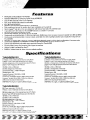
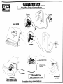
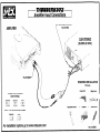
236T8302
introduction
CONGRATULATIONS
on your purchase of a new MTX
Thunder Amplifier! MTX has long been
the industry leader in mobile enclosures
and speakers, and we have reached
new heights with the development of
the new MTX Thunder amplifiers. You
couldn’t have chosen a more reliable,
powerful, or better performing amplifier
- In fact, we back up every Thunder
amplifier with a three-year warranty if
installed by an authorized MTX retailer
(see the warrantY statement).
Your new MTX Thunder amplifier was
designed, built and thoroughly tested at our
state-of-the-art electronics manufacturing
facility in Phoenix, Arizona. We manufacture
every amplifier using the latest Intelligent
Surface Mount Technology. Some of the
advantages of the new design are its significant improvements to the amplifier’s electrical and mechanical properties. ISMT
devices feature substantially shorter internal
and external lead lengths. This reduces stray
capacitance and inductance, which results
in cleaner and more accurate musical reproduction with significantly less noise interference. The ISMT mounter produces amplifier
boards with smaller and lighter components,
which are more resistant to vibrations inherent in the automotive environment.
A word about power ratings.It is importantfor you
to know how they stack up. MTX has chosenthe
most honest, most conservativeway to rate our
amps.We show you the RMSpower,at 12.5volts,
and dynamicpower at 14.4volts. However,we go
above and beyondthe call of duty. We test each
amplifier. The technician recordsthe “actual”
power output, and records this number on your
Certified Performance Certificate. The amplifier
must meet or exceed the rated specification
before we’ll ship it. No questions.No exceptions.
We want to ensure you get continuous
high performance from your MTX Thunder
amplifier, so we recommend that you have
it professionally installed by your authorized MTX dealer.
HOW TO USETHIS MANUAL
If you are installing this amplifier yourself,
we recommend that you read the manual
cover-to-cover
before you install it.
Familiarize yourself with the features and
details on the input and output panels. Make
sure you have all the equipment you need.
Sample installation diagrams may be found
on our website:
WWW.MTXAUDIO.COM.
If you have any questions, write or call us at:
MTX
4545E.BaselineRd.
Phoenix,AZ 85040
l-602-438-4545
1-800~CALL-MTX
[email protected]
www.mtxaudio.com
Registeryour warranty online
Features
l
*
*
l
l
l
l
*
l
l
l
.
l
.
l
*
l
l
Intelligent Surface Mount Technology
PatentedPWM MOSFETSwitchingPowerSupply(#5,598,325)
ClassA 100%DiscreteDriverCircuitTopology
New,more reliablehigh poweredtransformers
Pure N-Channel Design
Speaker and low level inputs Inputson Thunder6152
Color-codedwire harnessfor speaker-levelinput installationon Thunder6152
Smart-EngageTM
autoturn on for easy integrationwith factory head units (Thunder6152
only)
Input select 2CH/4CH switch on Thunder6304functionsas a built-in Y connector
RealIme ComputerizedProtectionCircuit
AcousticallySeamlessTurn-on/Turn-off(~.a.no noise1
Continuouslyvariable/defeatable12dB/octavehigh pass,24dB/octavemonolow pass crossover(variablefrom 40Hzto 200Hz)
Continuouslyvariable/selectablecrossoveroutput,switchablefrom full range/highpass/lowpassoutputs(Fullrangeonly on
Thunder63041
EBCMax on Thunder8302,allows for control of additionalsubwooferampsm a daisy chain configurationin low passmode
Contlnuouslvadjustableand defeatableThunderEQBassenhancementcircuitry, canteredat 40Hz
Left and right individuallyadlustableinput sensitivity(ExceptforThunder6304)
Nickel-plated, heavy duty terminal block type connectors
Untque rubber Insulated Iso-FeetTM
Buffered.isolatedoutput for daisy chainingmultipleamplifiers
Smzcifications
THUNDER6152
RMSPowermeasured
at 12.5VoltsDC
375Wattsx 2 mt” a 4 Ohmloadwithlessthan0.1%ThdtN
75Wattsx 2 mma 2 Ohmloadwithlessthan0.1%ThdtN
150Wattsbridgedmt” a 4 Ohmloadwithlessthan0 1%ThdtN
Dynamic
Powermeasured
at 144VoltsDC
90Wattsx 2lmt~a 4 Ohmload
I65Wattsx 2mt” a 2 Ohmload
325Wattsbridgedmt” a 4 Ohmload
SIgnalto NoseRat10>llOdBA-WeIghted
DampIng
Factor,200
, Frequency
Responses
20Hz-20kHz
f 025dB
MaxImum
Input.8Vrms
Thunder
E@Variable
BassBoostIO-l8dBlcentered
at 40Hz
Crossover:
Variable
40Hzto200Hz.
12dBioctave
highpass,
24dBiactave
lowpasswithm”“” output
Dlmensmns
8.3”x 9.75”x Y (21.lcmx 24.8cm
x 5.lcml
1O.rx 375”x 21” 1272cmx 248cmx 5.3cmlIncluding
lsoFeetTM
THUNDER8302
RMSPowermeasured
at 12.5VoltsOC.
75Wattsx 2intoa4 Ohmloadwithlessthan0 1%ThdtN
150Watlsx 2intoa 2 Ohmloadwithlessthan0 1%ThdtN
300wattsbridgedmma 4 Ohmloadwithlessthan0 1%ThdtN
Oynamlc
PowerIIHF-202
Standard)
measured
at 14.4VoltsDC
I20Waasx 2 mt” a 4 Ohmload
212Wattsx 2 mma 2 Ohmload
425Wattsbridgedmt” a 4 Ohmload
Smnalt” NmseRatio?llOdBA-Wemhted
Oampmg
Factor,200
Frequency
Response20Hz-20kHz
f 025dB
MaxImum
Inpu?8Vrms
Thunder
E@Variable
BassBoost(0.ISdB)centeredat40Hz
Crossover:
Variable
40Hzt” 200Hz,lZdBloctave
highpass,
24dBioctave
lowpasswl!hm”n” output
Dlmensmns
9.2nx 975”x Y (228cmx 22.8cm
x 5 lcml
II 5” x 3.75”x 2 I” (292cmx 248cmx 5.3cm)lncludlnglsoFe@’
THUNDER6304
RMSPowermeasured
at 12.5VoltsDC:
37.5Wattsx 4 mt” a4 Ohmloadwithlessthan03%ThdtN
75Wattsx 4 IntOa 2 Ohmloadwithlessthan0.3%ThdtN
I50Wattsx 2 bridgedmtaa 4 Ohmloadwithlessthan0.3%ThdtN
Dynamic
PowerlIHF-202
Standard)
measured
at 14.4VoltsDC
90wattsx 4 mtoa 4 Ohmload
I65Wattsx 4 mt” a 2 Ohmload
325Wattsx 2 bridgedmma 4 Ohmload
SIgnalto NoiseRatlo:tllOdB A-Welghted
DampIng
Factor:,200
Frequency
Response:
20Hz-20kHz
i 025dB
MaxImum
Input:8Vrms
Thunder
Ea:Vanable
BassBoostIO-18dB)
centeredat40Hz
Crossover:
Vanable
40Hzt” 200Hz,
12dBlactave
highpass,
24dBioctave
lowpasswith“0”” output
Dlmensmns.
l1.Y x 9.75”x 2” (29.2cm
x 24.8cm
x 5.lcm)
13.9”x 9.75”x 2 I” (35.3cm
x 24.8cm
x 5.3~~1
lncludmg
lsoFe@
1. Gain Controls-These controls are used to match the input sensitiviD/of the amplifier to the particular source
unit that You are using. The controls are factory set to 1Vrms. Note that the Thunder6304has a separate gain
control for front and rear channels.
2 RCAInput Jacks -These RCAinput jacks are for use with source units that have RCAor Line Level Outputs.
An independent set of jacks are provided on the Thunder6304for front and rear stereo inputs. A source unit with
a minimum level of 200mVis required for proper operation. The use of high quality twisted pair cables is recommendedto decrease the possibilin/ of radiated noise entering the system.
3. input Select 2CH/4CH - This switch, found on the Thunder6304,is used to match the amplifier’s input to the
source unit’s output so all four channels of the amplifier are driven. If your source unit has 2 outputs (a left and
right) connectthem to the amplifier’s front channel inputs, and place the input select switch in the 2CHposition.
If Your source unit has 4 outputs, (left front, left rear, and right front, right rear) connect them to the amplifier
inputs and place the input select switch in the 4CH postion. In the 4CH position, the fader on Your source unit
will operate.
4. Speaker Level Inputs-This input, found on the Thunder6152will allow the amplifier to operate from source
units with speaker-level outputs. Output speaker leads from the source unit should be tied directly to the wire
harness provided with the amplifier.
Wire harness color codes:
GreY/ Black = Source units right negative I-)
Solid Grey = Source units right positive (tj
White / Black = Source units left negative f-j
Solid White = Source units left positive (t)
With the Smart-EngageTM
auto-turncircuit, a remoteturn-onwire is not necessan/when connectingthe speaker-level
input wire harnessto a high poweredsource unit. The amplifierwill automaticallyturn on when music is received.
5. FrequencyControl-This control is continuouslyadjustablefrom 4OHzthrough 200Hz.Factorysettingis at 40Hz.
6. Crossover Select - This switch determines what type of signal comes out of the amp. If You select high pass,
the crossover slope is 12dB/stereo. If You select low pass, Your crossover slope will be 24dB/mono.Available
crossover frequencies are 40-200Hz.
7. Thunder EQ- This equalizationcircuit is used to enhance the low frequency response of the vehicle’s interior.
With up to 18 dB of boost and centered at 40Hz,the Bass EClcan be adjustedto meet Yourown personaltaste.
8. CompressionCircuit - This new circuit, found on the Thunder8302,prevents the amplifier from going into clipping, even at high SPLlevels.The compression circuit allows the listener to play the amplifier at high volume levels, Yet protects the speakers against the potential damagethat can occur during dynamic musical passages.The
circuit is switchable on/off, for those SPL competitors who run their amplifiers into clipping on purpose or 6152.
Warning - Damageto speakers may occur when the compression circuit is in the off position.
9. EBC2- The EBC,or Electronic Bass Control,allows a remote bass control to be adjusted from the driver’s seat.
If the optional EBCis installed, the bass level will be able to be adjusted to overcome noise and other interference. With EBC2 multiple amplifiers can be controlled. ( Not included on Thunder 6152or 6304)
IO. RCAOutputJacks and Switch- These RCAoutputs allow for a signal to be sent to other amplifiers in a daisychain configuration.. Youcan selectwhetherthe signal should be high pass, low pass or full range. In low pass
mode, the RCAoutputs allow for multiple bass amplifiers to be level controlled using one EBC. Onthe Thunder
6304,the RCAoutput jacks provide a line level full-range summed output of the Right Front/Right Rear and Left
Front/Left Rear input signals.
Inaut
Panel
Lavout
1. Fuses- For convenience,all amplifiers utilize ATCtype fuses. For continued protection in the event that a fuse
blows, replace the fuse only with the samevalue.
Caution - The power fuses on the amp are for protecting the amp against overdrive. To protect the vehicle’s
electrical system,an additionalfuse is requiredwithin 18” of the battery on the 12Vt cable.
Thunder6152- 30A
Thunder6304- 25Ax 3
Thunder8302- 30Ax 2
2. PowerTerminal- Thisterminal is where the powersource of the vehicle is connected. The 12Vt mustbe connected
directly to the positive battery post. It is highly recommendedthat you place an additionalfuse within 18” of the battery connection. Be sure to usethe correct gaugeof power cable! If wire of insufficient size is used,there will be a
voltage drop andthe ampwill starve,causingpoor performance. In an extremecase,the ampmay shut down dueto
the low battery voltage protection feature. The terminal closest to the fuse(s) is where the power cable with connector should be installed. Be sure to make your connection clean to avoid any shorting to the other terminals.
Always double check all of the connectionsfor any discrepancies.
Thunder6152- 10 Gauge
Thunder6304 - 6 - 8 Gauge
Thunder8302- 8 Gauge
3. RemoteTerminal - This is the wire that turns the amplifier on and off. This terminal connectsto the ampturn-on
lead or the power antennalead comingfrom the source unit. If the source unit doesn’t have one of these wires, you
can either run a wire to the battery with a switch or use an ignition controlledwire to power up the amp. If you use
the ignition controlled wire, be aware that the amplifier will be on, as long as the car is on. When using the Smart
EngageTMfeature,
a high poweredradio, and speakerlevel inputs it is not necessaryto connectthe RemoteTerminal.
4. GroundTerminal- The groundterminal connectsthe amplifierto the vehicle ground. Be sure to usethe samesize
wire gaugeor larger as the t12V connection. A strong groundpoint is very important. A little screw throughthe body
is not acceptable. The cable shouldbe as short as possibleand connectedto the chassisof the vehicle. The contact
point should be free of paint and debris for best results. All precautionsfor the 12Vt connectionapply to this connection as well.
5. Speaker Terminals -As shown in the wiring diagrams, be sure to observe speaker polarity through the
system. Failing to wire the speakers in proper phase could result in a loss of bass response and/or poor
overall sound quality. CAUTION: Thunder Amplifiers are not recommended for loads below 2 ohms stereo
or 4 ohms bridged.
Outnut
Q
Q
Panel
Lavout
Q
+ R - REARL+
Q
Aafiustina
the
Gain
Tvroical
SD,eaker
Wiring
Confirrurations
1. Turn the gain controls on the amplifier all the way down.
2. Turn up the volume control on the source unit to
approximately 3/4 of maximum.
Stereo Amplifier
Bridge Mode Application
Impedance Requirement
3. Adjust one gain control on the amplifier until audible
distortion occurs.
4 ohm bridge minimum
2 ohm stereo minimum
4. Adjust that same gain control down until audible
distortion disappears.
5. Follow steps 3-4 for other gain control settings.
6. When the Thunder 6152 and 8302 is bridged, adjust only
the left channel gain control.
7. The amplifier is now calibrated to the output of the
source unit.
Definitions
Common
of
Terms
The following list of terms with their definitions is
offered as help in understanding the set-up and operation of your amplifier.
1. Crossover (xover) - an electrical filter with high-pass or
low-pass characteristics that divides the frequency range
into playable bands for certain speakers. Subwoofers, midbass, midrange and tweeters are all designed to play different frequencies and should do so to avoid damage. The
xover point is where the playable frequencies cross from
one speakerto the next at -3dB below reference level.
2. Full-range - refers to signals which cover the entire audio
frequency span from 20Hzto 2OkHz.
3. High-pass - simply put, this blocks lower frequencies
which damage smaller speakers, and passes the higher
frequencies for smaller speakers like the midrange and
tweeter.
4. low-pass -You got it, this is the inverse of a high-pass. It
blocks higher frequencies and passes the playable lower
frequencies to the larger speakers, like subwoofers.
5. Impedance - the resistance to the flow of current in an
alternating current circuit (such as with music). Line level
circuits are typically a high impedance of several thousand
ohms, while speaker level circuits are usually a low impedance of a few ohms.
6. line level - The D/pe of signal produced at the outputs of
tape decks, CD tuners, preamplifiers, etc., with a D/pica1
value of a volt or less in a high impedance circuit.
7. Speaker level - The type of output that is meant to drive
speakers. These signals are sometimes called high level
and are uSually connected by two conductor speaker wires
8. Signal - The signal of an audio system is what is heard
from the speakers. These signals may be high pass, low
pass or full-range.
We don’t have enough space for Electronics 101,so if you
have a good, bad or amusing question, please call us TOLL
FREEat 800.CALL-MTX!(800-225-5689)
Troubleshootina
Guide
Readthis if you wannabe a do-it-yourselfer-- or give us a call at I-800~CALLMTX
Problem
No LEDindication
solution
Not12V at remoteconnection
No t12V at Powerconnection
Supplyt12Vto terminal
Supplyt12Vto terminal
Insufficientgroundconnection
Verifygroundconnection
Blownpowerfuse
LEDon,no output
Volumeon headunit off
Speakerconnectionsnot made
Gaincontrolon amplifieroff
Signalprocessingunitsoff
All speakersblown
Outputdistorted
Headunitvolumesettoo high
Amplifiergainsettoo high
Balancereversed
Somebalancereversed
Replacefuse
Increasevolumeon headunit
Makespeakerconnections
Turnup gain
Applypowerto signalprocessor
Replacespeakers
Lowerheadunit volume
Loweramplifiergain
Speakerswired L $ Rreversed
RCAinputsreversed
Wire speakerswith correctorientation
SomeSpeakerswired L t R
Wire speakerswith correctorientation
ReverseRCAinputs
reversed
SomeRCAinputsreversed
ReverseappropriateRCAinputs
Bassis boomy
ThunderEQtoo high
Bassis weak
ThunderEQtoo low
Raisesetting
Speakerswired out
Wire with correctphase
of phase
Not usingMTXwoofers
Blowingfuses
Excessiveoutputlevels
Amplifierdefective
Lowersetting
BuyMTXwoofers
Lowervolume
Returnfor service
Warrantv
All MTX Thunder Amplifiers purchased in the USA are guaranteed against defects in
material and workmanship for a period of three years from the date purchased by the
end user, if the amplifier is installed by an authorized MTX dealer (one year, if
installed by the consumer). This warranty is limited to the original retail purchaser of
product. MTX disclaims any liability for the other incurred damages resulting from
product defects. Any expenses incurred in the removal and reinstallation of
amplifiers are not covered by this warranty. MTX’s total liability will not exceed the
purchase price of the amplifier. This warranty is valid only in the USA.
To ensure efficiency and full benefit on any warranty claim during the warranty
period stated above, MTX requests the return of the warranty registration card,
completed in full immediately following purchase. Proof of purchase must be
provided at time of warranty claim. If there is no proof of purchase provided with the
warranty claim, MTX reserves the right not to honor the warranty set forth above.
Therefore, labor and parts may be charged to you.
This warranty does not apply to product exterior and cosmetics. Misuse, abnormal
service or handling, improper alterations or modifications in design or construction
void this warranty.
No sales personnel of the seller, or any other person is authorized to make any
warranties other than those described above or to extend the duration of any
warranties on behalf of MTX beyond the time period described above.
For Warranty Inquiries, please call:
l-800-225-5689
I-602-438-4545
MTX
4545 E. Baseline Rd.
Phoenix, Arizona 85040
Register Warranty On-line:
www.mtxaudio.com
Amplifier Output Connections
Stereo
AMPLIFIER
----
‘-, I__-.
.- -.-Ground
-
-. ‘-- -__....
To Metal Of Vehicle
/\/--,
d
Connect to Car Stereo
Remote/Power Antenna
Turn-On Wire
__---.
L
Grommet
Minimum Wire Size:
Disconnect
Battery Negative (-) Cable
Prior to Installing Amplifier
Power: 4 AWG.
For installation
options
Ground: 4 AWG.
go to www.mtxaudio.com
Remove Pain+
from Metal
-
7iiiiw~~t~~~O2
Amdifier
Input Connections
\
Remote/Power Antenna
Turn-On Wire
CAR STEREO
(SOURCE UNIT)
RCA Input1
REQUlRED4NSTALLATION
TOOLS:
Power Drill
Amplifier Crossover Select
Switch Settings:
Subwoofer
Separates
-
Co-Ax
rrml
m
m
LP FR HP
LP FR HP
LP FR HP
Adjustible
When used with Subwoofer
Seperates
Wrench
l
Crimpers
l
Screw Driver
Amplifier
Co-Ax
I
I
LP FR HP
LP FR HP
For installation
Utility Knife
options
go to www.mtxaudio.com
Part #: NDMl&
III II
Attn: Warranty Processing Center
4545 E. Baseline
Phoenix, AZ 85042-6400
II,,I,,I,I,II,,,,I,,III,,,,II,,,I,,III,,,II,,,,I,,I,I,I,,I,,II
Please fold and seal with tape
WARRANTYREGlSTRATlON&CUSTOMERSURVEY
NAME
AGE
PHONE
ADDRESS
OCCUPATION
CITY
DEALER
NAME
MTXMODELNO.
INSTALLED
BY
DATEPURCHASED
MAKE
YEAR
VEHICLE
TYPE
CI Purchased
for personaluse
1. WASTHISUNIT
MODEL
0
Received
as a gift
2. HOWDIDYOUFIRSTLEARNOFMTX?
CI Dealer
CI Radio
Ct TV
r;l Newspaper
i;l Catalog
Cl Friend/Family 0 Storedisplay
CarandTrack RollingStone Lowrider
c3 Magazine
(Circlethemagazine) MotorTrend
Truckin’ Autosound
andSecurity CarSound CarAudioandElectronics CarStereoReview
0 Other
3. ISTHIS:
Ci Yourfirstcarstereo 0 Replacement/Upgrade
4. WHATWASTHEMAINREASON
YOUSELECTED
THISMTXPRODUCT?
CI DealerrecommendationU MTXName/reputation
a Friend/family
recommendation
Cl Price
U Other~U Sound
CI Product
Appeal
5. WHATARETHREETHINGSYOULIKEMOSTABOUTTHISMTXPRODUCT?
U BassReproduction
CI SoundQuality
U Powerhandling
Cl Styling
0 Durability
D Installation
Flexibility
6. HOWSATISFIED
AREYOUWITHTHISPRODUCT?
a VerySatisfied
D Satisfied
tl Neutral
D NotSatisfied
7. WHEREDOYOUBUYYOURTAPESANDCD’S?
COMMENTS
NDM057
MOBILE DYNAMICS INSTALLATION SCHOOLS
EAST 1.800.325.0568
WEST 1.800.610.2122
INMOBILE
ELECTRONICS
INSTALLATION