1
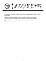
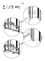
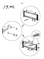
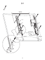
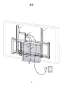
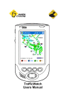
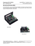
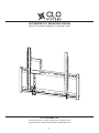
AUTOMATED TILT MOUNTING SYSTEM
MANUAL FOR MODEL NUMBERS: TP150B AND TC105B
CLO SYSTEMS, LLC
1501 W. Cameron Ave., Suite 215, West Covina, California 91790
T (626) 939-4226 / F (626) 939-3378 WWW.CLOSYSTEMS.COM
1
CAUTION: When using this automated tilt mounting system, basic precautions should always be followed,
including:
Follow the entire installation/user’s manual and the important safety instructions before attempting to install or
use this mounting system.
• Manufacturer is not liable for damage or injury caused by incorrect mounting, assembly, or use.
• The maximum weight this mounting system can support varies depending on the model number.
The model number for your mounting system is listed on the wall plate [01] and the box:
•
(1) TP150B: Fits most TVs from 40 in. to maximum of 60 in. weighing up to 150 lbs (68 Kg).
(2) TC105B: Fits most TVs from 40 in. to maximum of 52 in. weighing up to 105 lbs (48 Kg).
• Attaching
a TV that is heavier than the maximum weight specified above for the given model number may
result in instability, and possible personal injury.
• Only attach this mount system on vertical walls as instructed in this installation/user’s manual.
• This product is not designed for use in metal stud walls!
• If you have any doubts about the ability of the wall to support the TV and the mounting system, contact a
qualified contractor.
• Electrical Rating: DC 12V; 0.4A
• Unplug the power cord before servicing this mounting system.
• This mounting system may move the attached TV suddenly and without warning.
• Do not operate this mounting system when a person is near by, especially children!
• This product contains small items that could be a choking hazard if swallowed.
Keep these items away from children!
• Do not open the control box cover.
• For indoor use only.
• Do not run any wires and/or cables near moving parts of this mounting system.
• Do not operate this mounting system if the power cord or plug is damaged.
Engineered and Designed in the USA, and Assembled in China
PATENT PENDING
2
5mm
(3/16 in.)
13mm
(1/2 in.)
Supplied Parts and Hardware
Before starting assembly, verify all parts are included and undamaged. If any parts are missing or damaged, do
not return the item to your dealer; contact the customer service number listed on the cover page 1. Never use
damaged parts!
Hardware and procedures for multiple mounting configurations are included. When you see this
symbol, choose the correct configuration to suit your needs. Not all hardware included will be used.
OPT
CAUTION: This product contains small items that could be a choking hazard if swallowed.
Keep these items away from children!
3
[01] x 1
[06] x 1
[07] x 1
[02] x 1
[03] x 1
[08] x 1
[09] x 1
[04] x 1
[10] x 1
5/16 in.
[12] x 6
M4 x 12 mm
[15] x 4
[13] x 6
M5 x 12mm
[16] x 4
[14] x 6
M6 x 12 mm
M8 x 16 mm
[17] x 4
[18] x 4
M4 x 30mm
M5 x 30mm
M6 x 35mm
M8 x 40mm
[19] x 4
[20] x 4
[21] x 4
[22] x 4
M4
M5
[23] x 4
[24] x 4
M8
M6
[25] x 4
[26] x 4
M4 / M5
M6 / M8
M4 / M5
M6 / M8
[27] x 4
[28] x 4
[29] x 8
[30] x 4
4
[05] x 1
[11] x 1
1.0
5 mm
3/16 in.
30.4 ~ 61.0 cm
(12 ~ 24 in.)
6.35 cm
(2.5 in.)
[12]
[13]
5
1.0. Wood Stud Wall Mounting Applications
CAUTION: This product is not designed for use in metal stud walls. Do not over tighten the lag bolts [12].
Tighten the lag bolts only until they are firmly against the wall brackets [01].
Mount the wall bracket [01] to at least two (2) wooden studs spaced a minimum of 12 in. (30.4 cm) to a
maximum of 24 in. (61.0 cm) apart. Do not mount this mounting system to wooden studs smaller than
2 in. x 4 in. (51.0 mm x 102.0 mm). The gypsum drywall, lath, plaster, and the like covering may not exceed
1/2 in. (12.7 mm) thickness.
6
1.1
13 mm
1/2 in.
>46 cm
(18 in.)
>15 cm
(6 in.)
>15 cm
(6 in.)
>30 cm
(12 in.)
>64 m m
(2.5 in.)
[14]
>30 cm
(12 in.)
>15 cm
(6 in.)
[14]
[12]
7
[13]
1.1. Solid Concrete Wall Mounting Applications
CAUTION: Make sure concrete anchors [14] are seated flush with concrete surface. The gypsum drywall,
lath, plaster, and the like covering may not exceed 1/2 in. (12.7 mm) thickness.
CAUTION: Do not over tighten the lag bolts [12]. Tighten the lag bolts only until they are firmly against the
wall brackets [01].
8
2.0
<=800 mm
(31.5 in.)
TP150B
[03]
[02]
[04]
Digital optical audio output
> 38.1 mm
(1.5 in.)
[15, 16, 17, 18]
[23, 24, 25, 26]
[29, 30]
9
> 38.1 mm
(1.5 in.)
2.0. Mounting TV with a flat back
Note: The plastic cover (shown in dotted lines) is only provided on model number TP150B; but NOT on model
number TC105B. The pin [04] is shipped pre-inserted into the “STORE” opening on the bracket [03].
Note: Most flat screen TVs are provided with Digital Optical Audio Output on the back of the TV. If your TV has
one, locate the Digital Optical Audio Output – as this will be used later.
Position the motorized bracket [02] and the non-motorized bracket [03] on the back of the TV so that the
bottom of the two brackets [02] and [03] are at least 1.5 in. (38.1 mm) from the bottom of the TV.
Use the screws provided with the TV to attach the motorized bracket [02] and the non-motorized bracket [03] to
the back of the TV. If screws are not provided with the TV, then select the correct screw [15, 16, 17, 18] by
hand threading them into the threaded insert on the back of the TV. Stop immediately if you encounter any
resistance.
If the distance between the two threaded inserts on the back of the TV is greater than 31.5 inches (800mm),
then the two brackets [02] and [03] may not fit the wall brackets [01].
10
2.1
<=800 mm
(31.5 in.)
TP150B
[03]
[02]
[04]
Digital optical audio output
> 38.1 mm
(1.5 in.)
[19, 20, 21, 22]
[23, 24, 25, 26]
[29, 30]
[29] OPT
[27, 28]
11
> 38.1 mm
(1.5 in.)
2.1. Mounting TV with a curved back or obstruction
Note: The plastic cover (shown in dotted lines) is only provided on model number TP150B; but NOT on model
number TC105B.
Note: Most flat screen TVs are provided with Digital Optical Audio Output on the back of the TV. If your TV has
one, locate the Digital Optical Audio Output – as this will be used later.
Position the motorized bracket [02] and the non-motorized bracket [03] on the back of the TV so that the
bottom of the two brackets [02] and [03] are at least 1.5 in. (38.1 mm) from the bottom of the TV.
Select the correct screw [19, 20, 21, 22] by hand threading them into the threaded insert on the back of the TV.
Stop immediately if you encounter any resistance.
OPT
Use washer [29] with screws [19, 20] only.
If the distance between the two threaded inserts on the back of the TV is greater than 31.5 inches (800mm),
then the distance between the two brackets [02] and [03] may be too wide and they may not fit onto the wall
brackets [01].
12
3.0
13
3.0. Hang TV onto the wall bracket
You may need assistance with lifting the TV.
Remove the two screws on the bottom of the two brackets [02] and [03], and save these screws as they will be
used in the following steps.
Hang the two brackets [02] and [03] to the wall bracket [01].
Reinsert and tighten the bottom two screws to anchor the motorized bracket [02] and the non-motorized
bracket [03] to the wall bracket [01].
14
4.0
[02]
[03]
[06]
[08]
[07]
15
4.0. Electrical Connections
Note: Select the right electrical prong [09, 10, or 11] for your electrical socket.
(1) Refer to Section 9.0 and manually tilt the TV up, and insert the pin [04] to the “UP” opening to hold the TV
up for easier electrical connections.
(2) Insert the AC adapter jack [06] into the control box, and plug in the electrical prong to electrical socket.
(3) Insert the IR receiver jack [07] into the control box, and attach the head of the IR receiver [07] to the bottom
of the TV. Make sure the IR receiver [07] is visible from the front of the TV.
(4) Insert one end of the optical cable [08] to the control box, and the other end to the Digital Optical Audio
Output on the back of the TV. This mount system detects whether the TV is ON or OFF by detecting whether
the LED light (red) from the Digital Optical Audio Output is ON or OFF; and in Auto-Mode (refer to Section 9.0),
tilts the TV down when the LED light is ON, and returns the TV to the upright position when the LED light is
OFF.
Note: If the Digital Optical Audio Output of the TV is being used to drive speakers, then use an optical splitter
(not provided) to send signals to the control box.
Do not look into the LED light from the Digital Optical Audio Output, as this may cause temporary or
permanent injury to your eyes.
Do not run any wires and/or cables near moving parts of this mounting system. Run the cables and wires
through the shaded area as illustrated in Section 4.0 drawing.
16
5.0
~
~13
17
5.0. Adjusting the Tilt
Note: Section 5.0 only applies to Model Number TP150B. For Model Number TC105B, skip this Section and
go to the Section 7.0
(1) Use the down arrow button (
) on the remote control [05] to fully tilt down the TV. Refer to Section 9.0.
(2) The mounting system is design to tilt the TV down maximum of 13º.
Note: the maximum tilt angle may vary depending on the application such as the support wall and the weight
of the TV.
(3) Visually check to see if the TV tilts down fully. If the TV does NOT tilt down fully, then go to the next
Section 6.0. If the TV does tilt down fully, then skip to Section 7.0.
18
6.0
[03]
19
6.0. Removing the spring to tilt the TV down fully
Make sure the TV is in the upright position before proceeding with these steps!
(1) If the TV is not in the upright position, then use the up arrow button (
the TV.
) on the remote control [05] to tilt up
(2) Remove the two screws to take of the plastic cover off on the non-motorized bracket [03].
(3) Remove the screw holding the lever.
(4) Lower the lever to take the spring off.
(5) Return the lever to the original position.
(6) Reinsert the screw holding the lever.
(7) Insert the spring into the housing in the plastic cover for storage.
(8) Reinstall the plastic cover using the two screws.
Use the down arrow button (
) on the remote control [05] to tilt down the TV. The TV should now tilt down fully.
20
7.0
OPT
2
[02]
21
7.0. Optional: Adjusting the upright position of the TV
If desired, adjust the upright position of the TV by ± 2º by turning the bottom screw on the motorized bracket
[02].
22
8.0
STORE
P2
P1
UP
[03]
UP P2
[04]
P1
UP
P2
P1
STORE
STORE
23
8.0. Setting the preset position
Note: The pin [04] is shipped from the factory in the “STORE” opening.
(1) Insert the pin [04] into the “P1” opening for maximum preset tilt of about 6º.
(2) Insert the pin [04] into the “P2” opening for maximum preset tilt of about 9º.
(3) Insert the pin [04] into the “STORE” opening for full 13º tilt down position, and to store the pin [04].
(4) Insert the pin [04] into the “UP” opening to hold the TV up about 5º.
24
9.0
25
9.0. Remote control
Remote Control Buttons
Function Description
Up Key (
Tilts the TV up.
Down Key (
)
)
Tilts the TV down to a maximum of 13º.
STOP
Stops the movement.
AUTO
The factory default setting is Auto-Mode. If your TV is provided with a Digital
Optical Audio Output, and the optical cable [08] has been installed as instructed
in Section 4.0, then the Auto-Mode is functional. In Auto-Mode, the program will
automatically tilt down the TV when the TV is turned ON; and return the TV to
the upright position, when the TV is turned OFF. During operation, the UP/
DOWN/STOP buttons will override the Auto-Mode. The next time the TV is
turned ON or OFF, the program will go back to the Auto-Mode.
MANU
“MANU” will turns off the Auto-Mode. The program will only operate with the
remote control buttons.
RESET
Pressing the RESET KEY twice within 1 second will reset the program back to
the factory default settings, which is the Auto-Mode.
26
Troubleshooting
1. TV does not fully tilt down:
a. Possible cause: The mounting system relies on the weight of TV to tilt down the TV. Check to see if there is
any foreign object such as wire and cable stopping the TV from tilting down. If so, remove or relocate the
foreign object. Refer to Section 4.0.
b. Possible cause: The spring may be holding the TV up. Refer to Section 6.0 and remove the spring.
c. Possible cause: Check to see if the pin [04] is not in the “P1”, “P2”, or “UP” hole in the non-motorized
bracket [03]. Refer to Section 8.0.
2. TV stops moving up in middle of its operation:
a. Possible cause: Check to see if a foreign object is impeding the TV from moving upwards. If so, remove or
relocate the foreign object.
b. Possible cause: The weight of the TV may exceed the maximum weight limitation of the mounting system.
Refer to the wall bracket [01] for the model number for this mounting system: (1) TP150B ~ 150 lbs (68 Kg)
Max; and (2) TC105B ~ 105 lbs (48 Kg) Max. If the TV weight exceeds the maximum TV weight, then do NOT
use this product to support the overweight TV.
c. Possible cause: Program may be malfunctioning. Reset to factory setting by pressing “RESET” button on the
remote control [05]. Refer to Section 9.0.
3. TV does not automatically tilt down and up when the TV is turned ON and OFF:
a. Possible cause: “MANU” button may have been accidentally pushed. Push the “AUTO” button on the remote
control [05] to reset to Auto-Mode. Refer to Section 9.0.
b. Possible cause: Check to see if the optical cable [08] has been disconnected. Refer to Section 4.0.
4. The automated mount does not respond to remote control commands:
a. Possible cause: The IR receiver jack [07] may be disconnected from the control box. Refer to Section 4.0.
b. Possible cause: The IR receiver head [07] may be located in a poor location where it is difficult to receive the
IR signal from the remote control [05]. Relocate the IR receiver head. Refer to Section 4.0.
c. Possible cause: The AC power adapter jack [06] may be disconnected from the control box. Refer to
Section 4.0.
d. Possible cause: A foreign object may be impeding the movement of the TV.
e. Possible cause: The batteries in the remote control [05] may be bad. Replace the batteries.
5. TV leans forward in the upright position:
a. Possible cause: The weight of the TV is making the TV lean forward. Refer to Section 7.0 to adjust the
upright position of the TV.
27
Warranty
CLO Systems, LLC warrants its products, under normal use, to be free from defects in material and workmanship
for a period of one year from the date of purchase. Warranty covers parts only, and it does not cover labor.
Thereafter, repairs will be made at established factory prices. Unauthorized service or repairs by anyone other
than authorized CLO personnel renders this Warranty void and releases CLO from any further responsibility or
obligation. Attaching a load that is heavier than the maximum weight specified will void the warranty. Any damage
caused by failure to observe proper packing or to observe instructions for installation, by accident or in transit or
elsewhere will not be covered by the Warranty. This Warranty is in lieu of all other Warranties expressed or
implied, and no one is authorized to assume any liability on behalf of CLO or impose any obligation on it in
connection with the sale of any product other than as outlined above. In no event will responsibility be assumed
or implied for consequential damage arising from delay of installation, interrupted operation or other causes.
28
Disclaimer
CLO Systems, LLC makes no claim that the information contained herein covers all details, conditions, or variations.
Nor does it provide for every possible contingency in connection with the installation or use of this mounting system.
The information contained in this document is subject to change without notice or obligation of any kind. CLO
Systems makes no representation of warranty, expressed or implied, regarding the information contained herein.
CLO Systems assumes no responsibility of accuracy, completeness or sufficiency of the information contained
in this document.
29