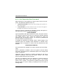
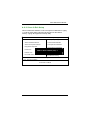
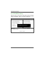
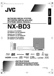
1
FPC 8084
All-in-One
8.4” Super Slim
PANEL PC
User’s Manual
Disclaimers
The information in this manual has been carefully checked and is believed to be
accurate. Acnodes Co., Ltd. assumes no responsibility for any infringements of
patents or other rights of third parties, which may result from its use.
Acnodes assumes no responsibility for any inaccuracies that may be contained in this
document. Acnodes makes no commitment to update or to keep current the
information contained in this manual.
Acnodes reserves the right to make improvements to this document and/or
product at any time and without notice.
No part of this document may be reproduced, stored in a retrieval system, or
transmitted, in any form or by any means, electronic, mechanical, photocopying,
recording, or otherwise, without the prior written permission of Acnodes Co., Ltd.
©Copyright 2005 by Acnodes Co., Ltd. All
rights reserved.
May 2005, Version A1
Printed in Taiw an
ii
Safety Approvals
CE Marking
FCC Class A
FCC Compliance
This equipment has been tested and complies with the limits for a
Class A digital device, pursuant to Part 15 of the FCC Rules. These
limits are designed to provide reasonable protection against harmful
interference in a residential installation. If not installed and used in
accordance with proper instructions, this equipment might generate or
radiate radio frequency energy and cause harmful interference to
radio communications. However, there is no guarantee that
interference will not occur in a particular installation. If this equipment
does cause harmful interference to radio or television reception, which
can be determined by turning the equipment off and on, the user is
encouraged to try to correct the interference by one or more of the
following measurers:
1. Reorient or relocate the receiving antenna.
2. Increase the separation between the equipment and
receiver.
3. Connect the equipment into an outlet on a circuit
different from that to which the receiver is connected.
4. Consult the dealer
technician for help.
or
an
experienced
radio/TV
Shielded interface cables must be used in order to comply with
emission limits.ou
iii
Safety Precautions
Before getting started, read the following important cautions.
1. The FPC 8084 does not come equipped with an
operating system. An operating system must be loaded
first before installing any software into the computer.
2. Be sure to ground yourself to prevent static charge when
installing the internal components. Use a grounding wrist
strap and place all electronic components in any
static-shielded devices. Most electronic components are
sensitive to static electrical charge.
3. Disconnect the power cord from the F P C 8 0 8 4 T
before making any installation. Be sure both the system
and the external devices are turned OFF. Sudden surge
of power could
ruin
sensitivecomponents.
Make
sure the FPC 8084 is properly grounded.
4. The brightness of the flat panel display decreases with
usage. However, hours of use vary depending on the
application environment.
5. Turn OFF the system power before cleaning. Clean the
system using a cloth only. Do not spray any liquid cleaner
directly onto the screen. The FPC 808 4 may come with
or w/o a touchscreen. Although the touchscreen is
chemical resistant, it is recommended that you spray the
liquid cleaner on a cloth first before wiping the screen. In
case your system comes without the touchscreen, you
must follow the same procedure and not spray any
cleaner on the flat panel directly.
6. Avoid using sharp objects to operate the touchscreen.
Scratches on the touchscreen may cause malfunction or
internal failure to the touchscreen.
7. The flat panel display is not susceptible to shock or
vibration. When assembling the F P C 8 0 8 4 , make sure it
is securely installed.
iv
8. Do not open the system s back cover. If opening the
cover for maintenance is a must, only a trained
technician is allowed to do so. Integrated circuits on
computer boards are sensitive to static electricity. To
avoid damaging chips from electrostatic discharge,
observe the following precautions:
9
Before handling a board or integrated circuit, touch an
unpainted portion of the system unit chassis for a few
seconds. This will help to discharge any static electricity on
your body. When handling boards and components,
wear
a wrist-grounding
strap, available from most
electronic component stores.
Trademarks Acknow ledgments
Acnodes is a trademark of Acnodes Co., Ltd.
IBM, PC/AT, PS/2, VGA are trademarks of I nternational
Business Machines Corporation.
I ntel and Pentium are trademarks of I ntel Corporation.
MS-DOS, Microsoft C and QuickBASIC are trademarks of
Microsoft Corporation.
VIA is a tradem ark of VIA Technologies, I nc.
SST is a trademark of Silicon Storage Technology, Inc.
UMC is a
Corporation.
tradem ark
of
United
Microelectronics
Other brand names and tradem arks are the properties of
their respective owners.
v
This page does not contain any information.
vi
Table of Contents
Chapter
1 Introduction............................................1
1.1 General Description .................................................1
1.2 Specifications ...........................................................2
1.2.1
1.2.2
1.2.3
Main CPU Board ......................................................2
I/O System ...............................................................2
System Specification ..............................................9
1.3 Dimensions .............................................................10
1.4
I/O Outlets..............................................................11
1.5 Package List............................................................12
Chapter
2 Hardware Installation ........................13
2.1 HDD Installation......................................................13
2.2 CF card Installation ..............................................15
2.3 Add-on Card Installation......................................16
2.4 3 x Serial Ports......................................................18
2.5 VGA ........................................................................20
2.6 Ethernet .................................................................20
2.7 Mountings: Panel / Wall / Desktop / VESA ..........21
2.7.1
2.7.2
2.7.3
VESA-ARM/Wall-Mount..........................................21
Desktop Kit Assembly.......................................22
Panel-mount Kit Assembly ....................................23
Chapter
3.1
3.2
3 Driver Installation...............................24
System ...................................................................24
Touch Screen ........................................................24
3.2.1 Specification..........................................................24
3.2.2 Driver Installation- Windows
98/2000/XP/CE.NET/XP-Embedded .................................25
3.2.3 Driver Installation- DOS.........................................27
3.2.3.1 Using INSTALL.EXE utility to install PenMount
software driver. ...................................................................27
3.2.3.2 Identify the communication port and IRQ number
27
Table of Contents
vii
3.2.3.3
3.2.3.4
3.2.4.5
3.2.4
3.2.4.1
3.2.4.2
3.2.4.3
Do Calibration .......................................................28
Initializing the PenMount driver ...........................29
Demonstration .......................................................29
Driver Installation- Linux .......................................29
Advance Setup .....................................................29
Install PenMount driver .........................................30
Do Calibration .......................................................31
Chapter
4 Embedded O.S. Installation ..............32
4.1
Windows XP Embedded ......................................32
4.1.1
4.2
Penmount Touch Screen ......................................32
Windows CE.NET 4.2............................................33
4.2.1
Calibration Touch Screen ....................................33
Appendix
A ...............................................................34
Main Board BIOS Setup ...................................................34
A.1 BIOS Introduction...................................................34
A.2 BIOS Setup ..............................................................34
A.2.1
A.2.2
A.2.3
A.2.4
A.2.5
A.2.6
A.2.7
A.2.8
A.2.9
A.2.10
A.2.11
A.2.12
A.2.13
viii
Standard CMOS Setup..........................................36
Advanced BIOS Features .....................................41
Advanced Chipset Features................................46
Integrated Peripherals..........................................49
Power Management Setup ..................................53
PNP/PCI Configuration .........................................56
PC Health Status ....................................................58
Frequency/Voltage Control ................................59
Load Fail-Safe Defaults.........................................60
Load Optimized Defaults......................................61
Set Supervisor/User Password..............................62
Save & Exit Setup...................................................63
Exit Without Saving................................................64
Table of Contents
FPC 8084 All-in-One PANEL PC User s Manual
Chapter
1
Introduction
This chapter contains the general information and the detail
specifications of the GOT-1840T. Chapter 1 includes the following
sections:
General Description
System Specification
Dimensions
1.1
I/O Outlets
Utilities Supported
Package List
General Description
The FPC 8084 is a fan-less and compact-size touch panel computer,
and is equipped with a 8.4" TFT LCD display and low power
consumption CPU, the VIA Eden 667MHz. The FPC 8084 supports
Windows® 98/NT/2000/XP, Windows® CE.NET, Windows® XP
embedded, and Linux. The panel also includes a PC/104 slot for
extended communication or a DA&C card. The FPC 8084 is costeffective choice for operator interface applications.
Reliable and Stable Design
The F P C 8 0 8 4 adopts a fan-less cooling system and a
CompactFlash™ card, which makes it especially suitable for
vibration-heavy environments, best for the transportation, ship, and
industrial machinery markets.
Flexibility- a PC/104 Slot
The FPC 8084 offers a PC/104 slot that allows for extended
communication or a DA&C card, or even for a PC/104 motion card,
which can be used for different application requirements. With
Windows a CE.NET and a CompactFlash™ card combination, the
Panel is especially suitable for embedded applications.
Embedded O.S. Supported
The FPC 8084 not only supports Windows® 98/NT/2000/XP, but
also supports embedded OS, such as Windows® CE.NET, and
Windows®
XP embedded. For storage device, the F P C
8 0 8 4 supports 2.5" HDD or CompactFlash™ card.
Introduction
1
FPC 8084 User s Manual
Industrial-grade Product Design
The FPC 8084 has an incredible design that can be used in different
industrial harsh environments.
z A fuse helps prevent over-voltage for power input.
z Stainless steel back chassis and Aluminum front bezel meets the
IP65/NEMA4 standard.
z For connecting other devices, the FPC 8084 also features
several interfaces: USB, Ethernet, and RS-232/422/485.
1.2
Specifications
1.2.1 Main CPU Board
CPU: VIA EDEN 400MHz, 667MHZ
System Chipset: VT8606 (Twister-T) + VT82C686B
BIOS: AWARD BIOS, Plug-and-Play 4Mbit Flash ROM
with SmartView VGA BIOS Function and
integrated Ethernet Novell RPL and Windows
PXE Boot ROM functions.
System Memory: One 14 4-pin DIMM socket.
Maximum up to 512MB SDRAM
ECC/parity
L2 Cache: Integrated in CPU
Watchdog Timer: Generates a system reset or NMI by
jumper selectable
Software programm able time interval
64 levels, 0.5~8/5~80/50~800/100~1600
seconds
1.2.2 I/O System
Standard I/O:
3 x serial ports with power;
2 x RS-232, 1 x
RS-232/422/485 jumper
selectable
1 x PS/2 Keyboard/Mouse
Interface
2
1x VGA Ports
2 x USB Ports 1.1 compliant
Introduction
FPC 8084 User s Manual
Ethernet:
- Realtek RTL 8100C PCI Bus 10/100M Base-T
- Wake-On-LAN
- RJ-45 interface equipped
Expansion Slot:
- one 16-bit PC/104 connector
1.2.3 System Specification
8.4” TFT LCD
Disk drive housing:
1 x internal 2.5” drive
100W DC power supply
Heat dispensing design
One slot for PC/104
Net weight:
18 Kgs
Dimension (main body size):
280 x 225 x 61.1mm
Operating temperature: -1O° to 45°C ; Relative
umidity:50%
Relative humidity: 10% to 85% @ 40° C, on-condensing
Altitude: 10,000 ft. (3,000 meters)
Vibration (operating):5 to 500 Hz, 1.3 G random
Shock (operating): 10 G peak acceleration (11 msec.
duration)
9
FPC 8084 User s Manual
1.3
Dimensions
The following diagrams show the dimensions and outlines of
FPC 8084.
10
FPC 8084 User s Manual
1.4
I/O Outlets
The following figure shows the I/O locations of the FPC 8084. Most of
the I/O connectors are located on the back panel of the
FPC 8084.
1
4
5
6
7
2
8
9
3
10
1:
USB v1.1
6:
Keyboard/Mouse
2:
COM4 Port
7:
USB v1.1
3:
Power Switch
8:
COM1 Port
4:
VGA Port
9:
COM2 Port
5:
LAN (RJ45)
10:
DC inlet
11
FPC 8084 User s Manual
1.5
Package List
When you receive the F P C 8 0 8 4 there are following items in
the package.
1. FPC 8084 x 1
2. Panel mount kit x 6
3. Desktop kit x 2
4. Desktop kit screw x 4
5. VESA ARM/Wall-mount kit x 1
6. CD driver x1
12
FPC 8084 User s Manual
Chapter
2
Hardware Installation
The FPC 8084 provides lots of flexible ways for you to select different
configuration such as HDD, CF card and more. The chapter will show
you how to install the hardware. It includes:
2.1
HDD Installation
The FPCC 8084 offers a convenient drive bay module for users to
install HDD. The FPC 8084 offers one 2.5” HDD drive for users to
install. Please follow the steps:
1. Open the HDD back chassis. Unscrew 4 screws of back and 4
screws of side. And take out the HDD bracket.
2. Screw 4 screws and fix HDD on the bracket kit.
13
FPC 8084 User s Manual
3. Fix the HDD bracket kit to system by 4 screws.
14
FPC 8084 User s Manual
2.2
CF card Installation
The F P C 8 0 8 4 offers a convenient drive bay module for users to
install CF card. When installing the CF card, refer to the following
instructions and illustration:
1. Open the bottom chassis.
15
FPC 8084 User s Manual
2. Install user’s CF card.
2.3
Add-on Card Installation
The FPC 8 0 84 provides one PC/104 slot. User could install one or
two PC/104 card. If user needs the PC/104 Box to protect add-on card,
user can order the ‘GOT-PC104-Kit’.
When upgrading the add-on card, refer to the following instructions
and illustration:
1. Remove the piece by 2 screws.
16
FPC 8084 User s Manual
2. Install PC/104 cards on the slot.
3. Set the bracket to protect.
17
FPC 8084 User s Manual
2.4
3 x Serial Ports
COM Port Connector: COM1
The connector, COM 1, is a DB-9 connector, and the following table
shows the pin assignments of this connector.
Pin
18
Signa l Na me
1
DCD, Data carrier detect
2
RXD, Receive data
3
TXD, Transmit data
4
DTR, Data terminal ready
5
GND, ground
6
DSR, Data set ready
7
RTS, Request to send
8
CTS, Clear to send
9
RI, Ring indicator
COM1
FPC 8084 User s Manual
COM Port Connectors: COM2, COM3, COM4
The RS-232 pin assignments are listed on the following table.
Pin
Description
1
3
Data
Ca rrie r
Dete ct
(DCD)
Receive Data (RXD)
4
Reques t to Send (RTS )
5
Trans mit Data (T XD)
6
Clear to S end (CT S)
7
Data Te rmin al
(DT R)
Grou nd (GND)
8
Ring Indicato r (RI)
10
NC
9
Pin
Rea dy
2
Description
Data Se t Ready (DS R)
1
3
2
4
5
6
7
9
8
10
19
FPC 8084 User s Manual
The RS-422/485 pin assignments for COM2 are listed below.
Signa l Name
Pin #
2.5
R2-422
RS- 485
1
TX-
DATA-
2
No connector
No connector
3
TX+
DATA+
4
No connector
No connector
5
RX+
No connector
6
No connector
No connector
7
RX-
No connector
8
No connector
No connector
9
GND
GND
10
No connector
No connector
VGA
The FPC 8084 has an analog RGB interface connector. It is able to
connect to an expansion CRT monitor, and the system can display on
both the flat panel and the CRT simultaneously.
2.6
Ethernet
Ethernet PJ-45 Connector: LAN1
The FPC 8084 is equipped with a high performance Plug and Play
Ethernet interface which is fully compliant with the IEEE 802.3
standard, and consisting of a RJ-45 connector LAN
3.4.15.1 Pin Assignment
LAN1: RJ-45 Connector Pin Assignment
Pin
1
2
3
20
Signal
Tx+ (Data transmission positive
Tx- (Data transmissionnegative)
Rx+(Data reception positive)
FPC 8084 User s Manual
4
RJ45 termination
5
RJ45 termination
6
Rx- (Data reception negative)
7
RJ45 termination
8
RJ45 termination
1 2 3 4 5 6 7 8
RJ-45
2.7 Mountings: Panel / Wall / Desktop /
VESA
There are 5 application options for the FPC 8084,
Panel/Wall/Desktop/VESA mountings.
2.7.1 VESA-ARM/Wall-Mount
The FPC 8084 provides two ways for VESA mount: 75x75 mm Screw
four screws to fix the kit (included in the package) in the back chassis.
21
FPC 8084 User s Manual
2.7.2 Desktop Kit Assembly
The FPC 8084 is designed for desktop application. The standard set of
desktop kit is included in the system packaging. Screw 4 screws to fix
the kit (included in the package) in the side chassis.
22
FPC 8084 User s Manual
2.7.3 Panel-mount Kit Assembly
The FPC 8084 is designed for panel mount application. To mount
the FPC 8084, the standard set of mounting kit (included in the
system packaging) is needed.
23
FPC 8084 User s Manual
Chapter
3
Driver Installation
3.1
System
FPC 8084 could support with Windows 95, Windows 98 or Windows
2000/XP. To facilitate installation system driver, you should read the
instructions in this chapter carefully before you attempt installation.
1.
Insert Driver CD and select the “\Driver\”.
2.
Select all files and follow the install procedure and press OK.
3.2
Touch Screen
3.2.1
Specification
Touch Screen:
For 8-wire analog resistive type
Touch Screen Co ntroller:
DMC9000
Comm unicatio ns:
RS-232
Baud Rate:
19200 baud rate fixed
Re solutio n:
1024 x 1024 (10-bit A/D converter inside)
Po wer Input:
5V to 12V DC
24
FPC 8084 User s Manual
Po wer Consum pt ion:
12V: 27mA+ i where (i = v/touch screen sheet
R) 5V: 23mA+ i where (i = v/touch screen
sheet R)
Board Size:
6.0 x 2.0 cm
Portrait:
Support 90o to 270o screen rotation
Stat ic Pro te ction:
ESD device option
Other s:
Touch activate indication LED on board
3.2.2
Driver Installation- Windows
98/2000/XP/CE.NET/XP-Embedded
The touch screen of FPC 8084 provides a driver for use with Windows
95, Windows 98 or Windows 2000/XP. To facilitate installation of the
touch screen driver, you should read the instructions in this chapter
carefully before you attempt installation.
1.
Insert Driver CD and select the “\Driver\Touch
\Windows 9x or 2k or XP or CE\Setup.exe”
2.
Follow the install procedure and press OK.
3.
Click Start menu and select “PenMount Utilities”. You can see
25
FPC 8084 User s Manual
PenMount Control Panel
4.
Select the “Standard Calibrate” tab
26
FPC 8084 User s Manual
5.
Calibration:
To adjust the display with touch panel, click “Calibration” and follow the
calibrate point to do calibration; there are five points on screen for
calibration.
6.
Press OK.
3.2.3
Driver Installation- DOS
3.2.3.1 Using “INSTALL.EXE” utility to install
PenMount software driver.
1.
Insert Driver CD and select the “Driver\Touch screen\DOS\
Install.exe
2.
Press ENTER key to install the drivers to drive C or use keyboard
to key-in the hard disc drive that you plan to install the driver.
3.
The driver will ask “Do you want to modify your Autoexec.bat to
initialize PenMount? (Y/N)” Suggest you choose “YES” for
generating the initialization instructions in AUTOEXEC.BAT files.
Then follow up the instructions to complete the installation.
3.2.3.2 Identify the communication port and IRQ
27
FPC 8084 User s Manual
number
1. For the first time installation, or changing PenMount Touch
Screen’s COM port, use PMDETECT (e.g.
C:\PENMOUNT\PMDETECT) to check the COM port and IRQ
number. PMDETECT will save the correct data to PMOUSE.CFG
file for further use.
The driver detects your communication COM port and IRQ number
from COM1 IRQ4, COM2 IRQ3, COM3…. to COM4 IRQ15.
PenMount driver can find the COM port and IRQ number
automatically. The screen will then show:
PenMount is initialized successfully!!!
Create file “pmouse.cfg”. Success.
PenMount internal settings:
Comm. Port: COM<n> IRQ<n>
..........
1. PMDETECT program is able to skip the IRQ number detecting if
you Touchscreen Driver Installation 13 do not need to detect the
specified IRQ number. For example, you do not need to detect
IRQ5, and the command is:
C:\PENMOUNT\PMDETECT -N5
If you do not need to detect IRQ5 and IRQ9, the command is:
C:\PENMOUNT\PMDETECT -N5 -N9
3.2.3.3 Do Calibration
1. To adjust the touch screen mapping properly to display screen,
use PM.BAT (C:\PENMOUNT\PM) to do calibration. Choose “1”
DO CALIBRATION (adjust screen mapping).
2. The message on screen asks you to select video mode number.
Select
by keyboard to start the calibration, touch the upper-center point, then
28
FPC 8084 User s Manual
right-center point, bottom-center point and left-center point in
sequence. After calibration, the data is shown in the screen, press any
key to continue the progress.
3. After the calibration, suggest you to test touch screen and display
mapped results by choose “3” DRAWING TEST under PM.BAT
3.2.3.4 Initializing the PenMount driver
If you don’t have the initialization commands in AUTOEXEC.BAT,
initialize PenMount C:\PENMOUNT\PMINIT) controller before you use
the PenMount Touch Screen. The display will show the initialization
message:
PenMount V7.06 Copyright(c) SALT International Corp.
Test:COM<n> IRQ<n> (<n> is the number after PMDETECT done)
PenMount communication settings: COM<N> IRQ<n> Baud Rate:
<xxxx>
... ... ... ... ... ... ... ... ... ...
3.2.4.5 Demonstration
To demonstrate or test touch screen operation, selecting “3”
DRAWING
TEST in PM.BAT file of Utility Directory. Drawing on screen.The other
demonstration program called “ICECREAM.EXE” in the
“PENMOUNT” directory can also be applied.
3.2.4
.3.2.4.1
Driver Installation- Linux
Advance Setup
1. Before install the Touch Screen Driver, please open the file in
Linux
File /etc/rc.local
29
GOT-1840T User s Manual
2. Key-in the following words:
Setserial /dev/ttyS2 port 0x3e8 irq 10
(set COM3 as touch screen port)
3. Save and exit.
4. Please reboot.
5. After reset system, insert Driver CD.
3.2.4.2 Install PenMount driver
1.
Insert Driver CD and select the “Driver\Touch\Linux
XFree86 4.x.x Driver V2.1\Driver\penmount_drv.o”
2.
Follow the install procedure and press OK.
3.
Please reboot system.
30
FPC 8084 User s Manual
4.
Click Start menu and select “PenMount Utilities”. You can see
PenMount Control Panel
3.2.4.3 Do Calibration
1.
Insert Driver CD and select the “Driver\Touch\Linux
XFree86 4.x.x Driver V2.1\Calibration\ pencal-2.00”
2.
Follow the install procedure and press OK.
3.
Please reboot system.
31
FPC 8084 User s Manual
Chapter
4
Embedded O.S. Installation
4.1
Windows XP Embedded
Supported onboard devices are as follows:
Onboard Multi I/O
Floppy drive
16C550 U ARTs com patible serial port
IrD A for wireless comm unication
Onboard IDE
IDE HDD
USB
PS2 Keyboard and mouse
CRT/LCD display
10/100 base-T Ethernet
Compact flash
Onboard audio
Audio
Touch Screen
4.1.1
Penmount Touch Screen
FPC 8084 has Penmount touch screen on COM3, which is disabled
by default.
Before you can use and calibrate it, you should :
1. Set up Penmount touch device driver by executing
c:\Penmount\ Windows 2000-XP V4.01\setup.exe.
When installation finished, an icon PM appears on
Taskbar .
2. Calibrate Penmount touch by clicking on PM icon
and doing calibration
3. Restart computer.
32
FPC 8084 User s Manual
4.2
Windows CE.NET 4.2
Supported onboard devices are as follows:
Onboard Multi I/O
Floppy drive
16C550 U ARTs com patible serial port
IrD A for wireless comm unication
Onboard IDE
IDE HDD
USB
PS2 Keyboard and mouse
CRT/LCD display
10/100 base-T Ethernet
Compact flash
Onboard audio
Audio
Touch Screen
4.2.1
Calibration Touch Screen
In this image we add PenMount Touch drivers and utilities. It
is customized for 800 x 600.
Calibration:
1. Click “Calibration” on desktop to calibrate touch
screen.
2. In the start\programs menu, select “save registry”,
thus Calilbration data will be saved and effective in
next boot.
33
FPC 8084 User s Manual
Appendix
A
Main Board BIOS Setup
Appendix A describes the different settings available in the Award
BIOS that comes with the SBC84600 CPU card. Also, the instructions
on how to set up the BIOS configuration are contained in this chapter.
A.1 BIOS Introduction
The Award BIOS (Basic Input/Output System) installed in the system
ROM supports Intel Celeron processors in a standard IBM-AT
compatible I/O system. The BIOS provides critical low-level support
for standard devices such as disk drives, serial and parallel ports. It
also adds virus and password protection as well as special support for
detailed fine-tuning of the chipset controlling the entire system.
A.2 BIOS Setup
The Award BIOS provides a Setup utility program for specifying the
system configurations and settings. The BIOS ROM of the system
stores the Setup utility. When the computer is turned ON, the Award
BIOS is immediately activated. The following message will appear
on the screen:
Press <DEL> to Enter Setup
Then, press the <Del> key immediately to enter the Setup utility.
The
delay of pressing the <Del> key will cause POST (Power On Self Test)
to continue with the test routines, thus preventing invoking the Setup.
In this case, the system has to be restarted for entering the BIO setup
by pressing the ”Reset” button or simultaneously pressing the <Ctrl>,
<Alt> and <Delete> keys. Besides, turning the system OFF first and
then ON again can also restart the system.
When entering the Setup utility, the Main Menu screen will appear on
the screen. Various setup functions and exit choices can be selected
from this menu.
34
FPC 8084 User s Manual
In general, the arrow keys are used to highlight items, <Enter> to
select, the <PgUp> and <PgDn> keys to change entries, <F1> for
help and <Esc> to quit.
Phoenix – Aw ardBIOS CMOS Setup Utility
`
Standard CMOS Features
`
Advanced BIOS Features
Load Fail-Safe Defaults
`
Advanced Chipset Features
Load Optimized Defaults
`
Integrated Peripherals
Set Supervisor Password
`
Power Management Setup
Set User Password
`
PnP/PCI Configurations
Save & Exit Setup
`
PC Health Status
Exit W ithout Saving
Esc : Quit
F9: Menu in BIOS
F10 : Save & Exit Setup
`
Frequency/Voltage Control
ÇÈÆ
: Select Item
Time, Date, Hard Disk Type…
The section below the setup items in the Main Menu displays the
control keys for this menu. Another section located at the bottom of
the Main Menu, just below the control keys section, displays
information on the currently highlighted item in the list.
NOTE:
If the computer cannot boot after making and saving
system changes with Setup, the Award BIOS, via its built-in
override feature, resets your system to the CMOS default
settings.
Avoid making any changes to the chipset defaults are strongly
recommended. These defaults have been carefully chosen by both
Award and the system manufacturer to provide the absolute maximum
performance and reliability.
35
FPC 8084 User s Manual
A.2.1
Standard CMOS Setup
“Standard CMOS Setup” is used to record some basic hardware
configurations in the computer system and set the system clock and
error handling. If the motherboard is already installed in a working
system, there is no need to enter this option. However, the Standard
CMOS option has to be setup in any of the following situations: the
system hardware configurations are changed, the onboard battery
fails, and the configuration stored in the CMOS memory is lost or
damaged.
Phoe nix – Award BIOS CMOS Setup Utility
Standard CMOS Features
Date (mm:dd:yy)
Wed, Aug 7 2002
Time (hh:mm:ss)
13 :
9 : 11
Item Help
Menu Level f
f
f
f
f
IDE
IDE
IDE
IDE
Primary Master
Primary Slave
Secondary Master
Secondary Slave
None
None
None
None
Drive A
LCD Type
Screen Expansion
TV Type
Type During Post
Display Type After Post
Halt on
1.44M, 3.5 in.
T9 800x600 TFT
Enable
NTSCDisplay
VGA Default
VGA Default
All, But keyboard
Base Memory
Extended Memory
640K
65535K
Ç ÈÆÅ : M ov e
Change the
Day, month,
Year and
Century
Ente r: Select
+/-/P U/PD: Va lue
F10: Save ES C: Exit F 1:
Gene ral Help
F5: Previ ous V alue s F 6: F ail-Safe Defa ults F7 : Opti mized Defa ults
At the bottom of the menu are the control keys for the use of this
menu. The <F1> key can be pressed in each item field to display the
relevant information for help. The memory display at the lower
right-hand side of the menu is read-only. It will adjust automatically
36
FPC 8084 User s Manual
according to the memory changed. The following pages describe each
item of this menu.
37
FPC 8084 User s Manual
Date
The date format is <day>, <date> <month> <year>.
show the calendar.
day
date
Press <F3> to
The day of week, from Sun to Sat, determined by the
BIOS, is read only
The date, from 1 to 31 (or the maximum allowed in the
Month), can key in the numeric al / function key
month
The month, Jan through Dec.
year
The year, depends on the year of BIOS
Time
The time format is <hour> <minute> <second> accepting either function
key or numerical key. The time is calculated based on the 24-hour
military-time clock. For example, 1 p.m. is 13:00:00.
IDE Primary Master / Primary Slave / Secondary Master /
Secondary Slave
This category identifies the type of the channel that is installed in the
computer. There are 45 predefined types and 2 user definable types for
Enhanced IDE BIOS. Type 1 to Type 45 are predefined. Type User is
user-definable.
Press <PgUp>/<+> or <PgDn>/< > to select a numbered hard disk type
or type the number and press <Enter>. Note that the specifications of
the drive in the system must match with the drive table. The hard disk
will not work properly if the improper information within this category is
entered. If the disk drive type does not match or is not listed, the Type
User is used to define the drive type manually.
If the Type User is selected, related information has to be entered.
Enter the information directly from the keyboard and press <Enter>.
This information should be provided in the documentation from the hard
disk vendor or the system manufacturer.
If the controller of HDD interface is ESDI, select “Type 1”. If
the controller of HDD interface is SCSI, select “None”.
If the controller of HDD interface is CD-ROM, select “None”.
CYLS.
number of
cylinders
HEADS
number of heads SECTORS
PRECOMP
write precom
LANDZONE
MODE
landing zone
number of
sectors
HDD access
mode
If there is no hard disk drive installed, select NONE and press <Enter>.
38
FPC 8084 User s Manual
Drive A type/Drive B type
The category identifies the types of floppy disk drive A or drive B installed
in the computer.
None
No floppy drive installed
360K, 5.25 in
5.25 inch PC-type standard drive; 360Kb capacity
1.2M, 5.25 in
5.25 inch AT-type high-density drive; 1.2MB
capacity
720K, 3.5 in
3.5 inch double-sided drive; 720Kb capacity
1.44M, 3.5 in
3.5 inch double-sided drive; 1.44MB capacity
2.88M, 3.5 in
3.5 inch double-sided drive; 2.88MB capacity
Select Display Device
This item selection includes Auto, CRT, LCD and CRT+LCD
LCD Type
This item selection includes:
T0 640x480 TFT
1024x768 TFT
T4 640x480 DSTN
T6 1024x768 DSTN
T8 640x480 TFT
T10 1024x768 TFT
T12 1400x1050 DSTN
T14 1024x768 DSTN
T1 800x600 TFT T2
T3 1280x1024 TFT
T5 800x600 DSTN
T7 1024x768 TFT
T9 800x600 TFT
T11 1280x1024 TFT
T13 800x600 DSTN
T15 1280x1024 DSTN
Display Type During Post
This item selection includes VGA DEFAULT, CRT, LCD, CRT+LCD, TV,
and CRT+TV.
Display Type After Post
This item selection includes VGA DEFAULT, CRT, LCD, CRT+LCD, TV,
and CRT+TV.
39
FPC 8084 User s Manual
Halt On
This field determines whether the system will halt if an error is detected
during power up.
No errors
The system boot will halt on any error
detected. (default)
All errors
Whenever the BIOS detects a non-fatal
error, the system will stop and you will be
prompted.
All, But
Keyboard
The system boot will not stop for a
keyboard error; it will stop for all other
errors.
All, But Diskette
The system boot will not stop for a disk
error; it will stop for all other errors.
All, But Disk/Key
40
The system boot will not stop for a
keyboard or disk error; it will stop for all
other errors.
FPC 8084 User s Manual
A.2.2
Advanced BIOS Features
This section is used to configure and improve the system and set up
some system features according to the user’s preference.
Phoe nix – Award BIOS CMOS Setup Utility
Advanced BIOS Featur es
Virus Warning
CPU Internal Cache
External Cache
CPU L2 Cache ECC Checking
Processor Number Feature
Power On Self Test
First Boot Device
Second Boot Device
Third Boot Device
Boot Other Device
wap Floppy Drive
Boot Up Floppy Seek
Up NumLock Status
Gate A20 Option
Typematic Rate Setting
Typematic Rate (Chars/Sec)
Typematic Delay (Msec)
ty Option
OS Select For DRAM > 64MB
Video BIOS Shadow
C8000-CBFFF Shadow
CC000-CFFFF Shadow
D0000-D3FFF Shadow
D4000-D7FFF Shadow
D8000-DBFFF Shadow
DC000-DFFFF Shadow
Small Logo(EPA) Show
Ç ÈÆÅ : M ov e
Disabled
Enabled
Enabled
Enabled
Enabled
Enabled
HDD-0
Floppy
LS120
Enabled
Disabled
Enabled
On
Fast
Disabled
6
250
Setup
Non-OS2
Enabled
Disabled
Disabled
Disabled
Disabled
Disabled
Disabled
Disabled
Item Help
Menu Level f
Allows you toQuick
choose the VIRUS
warning feature
for IDE Hard disk
boot sector
protection. If thisS
function is enable
and someoneBoot
attempts to write
data into this area,
BIOS will show
a warning
message onSecuri
screen and alarm
beep
Ente r: Select
+/-/P U/PD: Va lue
F10: Save ES C: Exit F 1:
Gene ral Help
F5: Previ ous V alue s F 6: F ail-Safe Defa ults F7 : Opti mized Defa ults
41
FPC 8084 User s Manual
Virus Warning
This item protects the boot sector and partition table of the hard disk
against accidental modifications. If an attempt is made, the BIOS will halt
the system and display a warning message. If this occurs, the user can
either continue the operation or run an anti-virus program to locate and
remove the problem.
NOTE:
Many disk diagnostic programs, which attempt to access the
boot sector table, can cause the virus warning. Thus,
disable the Virus Warning feature while running any of these
programs..
CPU Internal Cache / External Cache
Cache memory is additional memory that is much faster than
conventional DRAM (system memory). CPUs from 486-type and up
contain internal cache memory, and most, but not all, modern PCs have
additional (external) cache memory. W hen the CPU requests data, the
system transfers the requested data from the main DRAM into cache
memory, for even faster access by the CPU. These items are used to
enable (speed up memory access) or disable the cache function. By
default, these are Enabled.
CPU L2 Cache ECC Checking
When enabled, this allows ECC checking of the CPU’s L2 cache.
default, this field is Enabled.
By
Processor Number Feature
W hen a Pentium® III CPU is installed, the system automatically detects it
and displays this item.
Quick Power On Self Test
This option speeds up Power On Self Test (POST) after turning on the
system power. If it is set as Enabled, BIOS will shorten or skip some
check items during POST. The default setting is Enabled .
Enabled
Enable Quick POST
Disabled
Normal POST
First/Second/Third Boot Device
These items allow the selection of the 1st, 2nd, and 3rd devices that the
system will search for during its boot-up sequence. The wide range of
selection includes Floppy, LS120, ZIP100, HDD0~3, SCSI, and CDROM.
Boot Other Device
This item allows the user to enable/disable the boot device not listed on
the First/Second/Third boot devic es option above. The default setting is
Enabled.
42
FPC 8084 User s Manual
Swap Floppy Drive
This allows you to determine whether to enable Swap Floppy Drive or not.
W hen enabled, the BIOS swaps floppy drive assignments so that Drive A
becomes Drive B, and Drive B becomes Drive A. By default, this field is
set to Disabled .
Boot Up Floppy Seek
During POST, BIOS will determine the floppy disk drive type, 40 or 80
tracks. 360Kb type is 40 tracks while 720Kb, 1.2MB and 1.44MB are all
80 tracks. The default value is Enabled .
Enabled
BIOS sea rches fo r flopp y disk drive to dete rmin e if i t is 40 or 80tra
cks. Note that BIO S can no t tell from 720K, 1.2 M or 1.44M drivetype
as they are all 80 tracks.
Disabled
BIOS will not sea rch fo r the type of flo ppy disk drive by tracknu
mbe r. Th ere will be no wa rnin g messa ge displaye d if t he d riveinst
alled is 360 K.
Boot Up NumLock Status
This option enables and disables the numberlock function of the keypad.
The default value is On .
On
Key pad functions confine wi th nu mb ers
Off
Keypad fu ncti ons convert to special functions (i.e., left/ right a rro w
keys)
Gate A20 Option
The default value is Fast .
Normal
The A20 sig nal is controlle d by keyb oard c ontroller or chipsetha
Fast
Default: Fa st. T he A20 sign al is controlle d b y P ort 92 or
rdwa re.
chips et s pecific m ethod.
Typematic Rate Setting
This determines the typematic rate of the keyboard.
Disabled .
The default value is
Enabled
Enable type m atic rate and typ e matic del ay progra mming
Disabled
Di sa ble type matic rate a nd typ e matic delay pro gram ming . The
syste m BIOS will use default valu e of these 2 items and the
default is controlled by k eyboard.
43
FPC 8084 User s Manual
Typematic Rate (Chars/Sec)
This option refers to the number of characters the keyboard can type per
second. The default value is 6 .
6
6 ch aracte rs pe r second
8
8 ch aracte rs pe r second
10
10 characte rs p er second
12
12 characte rs p er second
15
15 characte rs p er second
20
20 characte rs p er second
24
24 characte rs p er second
30
30 characte rs p er second
Typematic Delay (Msec)
This option sets the display time interval from the first to the second
character when holding a key. The default value is 250 .
250
250 msec
500
500 msec
750
750 msec
1000
1000 ms ec
Security Option
This item limits the access to the system and Setup, or just to Setup.
The default value is Setup .
System
The s yste m will no t boot and access to Setup will b e denied if th ein
correct p ass wo rd is en tered at th e pr ompt.
Setup
The s yste m will boot, but acces s to Setup will be deni ed if the
co rrect p ass word is not ente re d at th e pr om pt.
NOTE:
To disable security, select PASSWORD SETTING at
Main Menu and then password is asked to enter. Do
not type anything, just press <Enter> and it will
disable security. Once the security is disabled, the
system will boot and you can enter Setup freely.
OS Select for DRAM > 64MB
This segment is specifically created for OS/2 when DRAM is larger than
64MB. If the operating system is OS/2 and DRAM used is larger the
64MB, “OS 2” has to be selected; otherwise (under non-OS2), default is
“NON-OS2”.
44
FPC 8084 User s Manual
Video BIOS Shadow
Video shadowing increases the video speed by copying the video BIOS
into RAM. However, it is still optional depending on the chipset design.
The default value of this option is Enabled .
Enabled
Video BIOS shadowi ng is enabled
Disabled
Video BIOS shadowi ng is disa bled
C8000 - CBFFF Shadow/DC000 - DFFFF Shadow
Shadowing ROM reduces available memory between 640KB and
1024KB. These fields determine whether optional ROM is copied to RAM
or not.
45
FPC 8084 User s Manual
A.2.3
Advanced Chipset Features
Since the features in this section are related to the chipset on the
CPU board and are completely optimized, changing the default
settings in this setup table are not recommended unless the user is
well oriented with the chipset features.
Phoe nix – Award BIOS CMOS Setup Utility
Advanced Chipset Features
DRAM Timing By SPD
X DRAM Clock
X SDRAM Cycle Length
X Bank Interleave
Memory Hole
P2C/C2P Concurrency
System BIOS Cacheable
Video RAM Cacheable
Frame Buffer Size
Aperture Size
AGP-4X Mode
AGP Driving Control
Driving Value
OnChip USB
USB Keyboard Support
OnChip Sound
OnChip Modem
CPU to PCI Write Buffer
PCI Dynamic Bursting
PCI Master 0 WS Write
PCI Delay Transaction
PCI# 2 Access # 1 Retry
AGP Master 1 WS Write
AGP Master 1 WS Read
Ç ÈÆÅ : M ov e
Item Help
Menu Level f
+/-/P U/PD: Va lue
F10: Save ES C: Exit F 1:
Gene ral Help
F5: Previ ous V alue s F 6: F ail-Safe Defa ults F7 : Opti mized Defa ults
46
Ente r: Select
Enabled
Host CLK
3
Disabled
Disabled
Enabled
Disabled
Disabled
16MAGP
64M
Enabled
AutoAGP
DA
Enabled
Disabled
Auto
Disabled
Enabled
Enabled
Enabled
Disabled
Enabled
Disabled
Disabled
FPC 8084 User s Manual
DRAM Timing By SPD
This item is selected depending on whether the board has paged
DRAMs or EDO (extended data output) DRAMs.
DRAM Clock
The DRAM clock value is set depending on whether the board has paged
DRAMs or EDO (extended data output) DRAMs. The available choices
are 66 MHz and Host CLK.
SDRAM Cycle Length
When synchronous DRAM is installed, the number of clock cycles of CAS
latency depends on the DRAM timing. Do not reset this field from the
default value specified by the system designer. The default setting is 3.
Memory Hole
To improve performance, certain space in memory is reserved for ISA
cards. This memory must be mapped into the memory space below
16MB. The available choices are 15M-16M and Disabled.
P2C/C2P Concurrency
This item enables or disables the PCI to CPU and CPU to PCI
concurrency. By default, this field is set to Enabled.
System BIOS Cacheable
Selecting “Enabled
allows caching of the system BIOS ROM at
F0000h-FFFFFh, resulting in better system performance. However, if any
program writes to this memory area, a system error may result.
The choice: Enabled, Disabled.
Video RAM Cacheable
Selecting “Enabled” allows caching of the A/B segment, resulting in
better system performance.
The choice: Enabled, Disabled.
AGP Aperture Size
The field sets aperture size of the graphics. The aperture is a portion of
the PCI memory address range dedicated for graphics memory address
space. Host cycles that hit the aperture range are forwarded to the AGP
without any translation.
The choice: 4M, 8M, 16M, 32M, 64M, 128M and 256M.
OnChip USB
This should be enabled if the system has a USB installed on the system
board and the USB will be used. Even when equipped, if a higher
performance controller is added, this feature should be disabled.
The choice: Enabled, Disabled.
47
FPC 8084 User s Manual
USB Keyboard Support
Select “Enabled if the system contains a Universal Serial Bus (USB)
controller and you have a USB keyboard.
The choice: Enabled, Disabled.
CPU to PCI Write Buffer
W hen this field is Enabled , writes from the CPU to the PCI bus are
buffered to compensate for the speed differences between the CPU and
the PCI bus. W hen “Disabled , the writes are not buffered and the CPU
must wait until the write is complete before starting another write cycle.
PCI Dynamic Bursting
This item is to enable/ disable the PCI dynamic bursting function.
PCI Master 0 WS Write
W hen Enabled , writes to the PCI bus are executed with zero wait
states.
PCI Delay Transaction
The chipset has an embedded 32-bit posted write buffer to support delay
transactions cycles. Select Enabled to support compliance with PCI
specification version 2.1. The default setting is Disabled.
PCI#2 Access #1 Retry
W hen Disabled , PCI#2 will not be disconnected until access finishes
(default). W hen Enabled , PCI#2 will be disconnected if max retries
are attempted without success.
AGP Master 1 WS Write
W hen Enabled , writes to the AGP (Accelerated Graphics Port) are
executed with one wait states.
AGP Master 1 WS Read
W hen Enabled , read to the AGP (Accelerated Graphics Port) are
executed with one wait states.
48
FPC 8084 User s Manual
A.2.4
Integrated Peripherals
This option sets the hard disk configuration, mode and port.
Phoe nix – Award BIOS CMOS Setup Utility
Integrated Peripherals
OnChip IDE Channel0
Enabled
Item Help
OnChip IDE Channel1
Enabled
IDE Prefetch Mode
Enabled
Menu Level f
Primary Master PIO
Auto
Primary Slave PIO
Auto
Secondary Master PIO
Auto
Secondary Slave PIO
Auto
Primary Master UDMA
Auto
Primary Slave UDMA
Auto
Secondary Master UDMA
Auto
Secondary Slave UDMA
Auto
Init Display First
P CI Sl ot
IDE HDD Block Mode
Enabled
Onboard FDD Controller
Enabled
Onboard Serial Port 1
3F8/IRQ4
Onboard Serial Port 2
2F8/IRQ3
UART 2 Mode
Standar d
IR Function Duplex
Half
TX, RX inverting enable
No, Yes
Onboard Parallel Port
378/IRQ7
Onboard Parallel Mode
Normal
X ECP Mode Use DMA
3
X Parallel Port EPP Type
EPP1.9
Onboard Serial Port 3
3E8H
Ser ial Port 3 Use IRQ
IRQ 10
Onboard Serial Port 4
2E8H
Ser ial Port 4 Use IRQ
IRQ 11
Onboard Legacy Audio
Enabled
X Sound Blaster
Di sabl ed
X SB I/O Base Address
220H
X SB IRQ Select
IRQ 5
X SB DMA Select
DMA 1
X MPU-401
Disabled
X MPU-401 I/O Address
330-333H
Ç ÈÆÅ : M ov e
Ente r: Select
+/-/P U/PD: Va lue
F10: Save ES C: Exit F 1:
Gene ral Help
F5: Previ ous V alue s F 6: F ail-Safe Defa ults F7 : Opti mized Defa ults
49
FPC 8084 User s Manual
On-Chip IDE Channel0/Channel1
The integrated peripheral controller contains an IDE interface with
support for two IDE channels. Select “Enabled to activate each channel
separately.
The choice: Enabled, Disabled.
IDE Prefetch Mode
The onboard IDE drive interface supports IDE prefetching for faster drive
acc esses. If a primary and/or secondary add-in IDE interface are installed,
set this field to “Disabled if the interface does not support prefetching.
Primary/Secondary Master/Slave PIO
The four PIO (Programmed Input/Output) fields sets a PIO mode (0-4) for
each of the four IDE devices that the onboard IDE interface supports.
Modes 0 through 4 provide successively increased performance.
In
Auto mode, the system automatically determines the best mode for each
device.
The choice: Auto, Mode 0, Mode 1, Mode 2, Mode 3, Mode 4.
Primary/Secondary Master/Slave UDMA
Ultra DMA/33 implementation is possible only if your IDE hard drive
supports it and the operating environment includes a DMA driver
(W indows 98 or a third-party IDE bus master driver). If the hard drive and
the system software both support Ultra DMA/33, select Auto to enable
BIOS support.
The Choice: Auto, Disabled.
Init Display First
This item is to active whether PCI Slot or on-chip VGA first.
The choice: PCI Slot, Onboard.
IDE HDD Block Mode
Block mode is also called block transfer, multiple commands, or multiple
sector read/write. If the IDE hard drive supports block mode (most new
drives do), select Enabled for automatic detection of the optimal
number of block read/writes per sector the drive can support.
The choice: Enabled, Disabled
Onboard FDD Controller
Select Enabled if the system has a floppy disk controller (FDC)
installed on the system board and the FDC will be used. If the and-in
FDC are installed or the system has no floppy drive, select Disabled in
this field.
The choice: Enabled, Disabled.
50
FPC 8084 User s Manual
Onboard Serial Port 1/Port 2
Select an address and corresponding interrupt for the first, second and
twist serial ports.
The choice: 3F8/IRQ4, 2E8/IRQ3, 3E8/IRQ4, 2F8/IRQ3, Disabled, Auto.
UART 2 Mode
This item a is to select UART mode. By default, this field is set to
Standard.
IR Function Duplex
This item is to select the IR half/full duplex function.
TX,RX inverting enable
This item is to enable the TX, RX inverting which depends on different
H/W requirement. This field is not recommended to change its default
setting for avoiding any error in the system.
Onboard Serial Port 3
This item allows you to determine access onboard serial port 3 with
which I/O address. The options available are
3F8H/2F8H/3E8H/2E8H/Disabled.
Serial Port 3 Use IRQ
Select an corresponding interrupt for the 3rd. serial port. The options
available are IRQ10/11/3/4/5/7/9.
Onboard Serial Port 4
This item allows you to determine access onboard serial port 4 with
which I/O address. The options available are
3F8H/2F8H/3E8H/2E8H/Disabled.
Serial Port 4 Use IRQ
Select an corresponding interrupt for the 4th. serial port. The options
available are IRQ10/11/3/4/5/7/9.
Onboard Parallel Port
This item is to determine access onboard parallel port controller with
which I/O address.
The choice: 3BC/IRQ7, 378/IRQ7, 278/IRQ5, Disabled.
Onboard Parallel Mode
Select an operating mode for the onboard parallel (printer) port. Select
Normal, Compatible, or SPP unless you are certain your hardware and
software both support one of the other available modes.
The choice: SPP, EPP, ECP, ECP+EPP.
ECP Mode Use DMA
51
FPC 8084 User s Manual
Select a DMA channel for the parallel port for use during ECP mode.
The choice: 3, 1.
52
FPC 8084 User s Manual
A.2.5
Power Management Setup
The Power Management Setup is to save energy of the system
effectively. It will shut down the hard disk and turn OFF video display
after a period of inactivity.
Phoe nix – Award BIOS CMOS Setup Utility
Pow er Management Setup
ACPI Function
Disabled
Item Help
Power Management
Press Enter
PM Control by APM
Yes
Menu Level f
Video Off Option
Suspend -> Off
Video Off Method
V/H SYNC+Blank
MODEM Use IRQ
3
Soft-Off by PWRBTN
Instant-Off
Wake Up Events
Press Enter
Ç ÈÆÅ : M ov e
Ente r: Select
+/-/P U/PD: Va lue
F10: Save ES C: Exit F 1:
Gene ral Help
F5: Previ ous V alue s F 6: F ail-Safe Defa ults F7 : Opti mized Defa ults
ACPI Function
This item is to enable/disable the Advanced Configuration and Power
Interface (ACPI).
The choice: Enabled, Disabled.
Power Management
This item is to select the Power Management mode.
The choice: User Define, Min Saving, Max Saving.
PM Control by APM
When enabled, an Advanced Power Management device will be
activated to enhance the Max. Power Saving mode and stop the CPU
internal clock. If Advance Power Management (APM) is installed on the
system, selecting Yes gives better power savings. If the Max. Power
Saving is not enabled, this will be preset to No .
53
FPC 8084 User s Manual
Video Off Option
W hen enabled, this feature allows the VGA adapter to operate in a power
saving mode.
Always On
Monito r will remain on du ring p o we r saving modes.
Suspend --> Off
Monito r bla nked wh en the sys te m ente rs the Su sp end
Susp,Stby --> Off
Monito r bla nked wh en the sys te m ente rs eithe r
Sus pend or St and by mo de s.
All Modes --> Off
Monito r blanked wh en the system e nte rs any powe r
mode.
saving mode.
Video Off Method
This determines the manner in which the monitor is blanked.
V/H SYNC +
Blank
This causes the syste m to turn off th e vertical and horizontals
ync hro nization po rts and w rite blanks to th e vid eo buffe r.
Selec t this optio n if y ou r monitor su pports the Display Po we r
Management Signalin g (DPMS) sta nd ard of th e Vid eoElectr
onics Stand ards to sel ect vid eo power manage m entvalues .
DPMS
Blank Screen
This option only writes blank s to the video buffer.
Video Off Method
In suspending, this item is to select the CRT closed method under APM
mode.
The choice: Blank Screen, V/H SYNC+Blank, DPMS
MODEM Use IRQ
APM 1.2 function used only.
The choice: NA, 3, 4, 5, 7, 9, 10, 11
Soft-off by PWRBTN
This only works with the system using an ATX power supply. It also
allows user to define the type of soft power OFF sequence for the system to
follow.
Instant-Off
(default)
This option follo ws the co nventiona l manne r s ystems pe rform whenp
o wer is turne d O FF. Insta nt-Off is a s oft p ower OFF s equencerequ
iring only the s witching of the power s upply button to OFF.
Delay 4 Sec.
Upon turning O FF syst e m fro m the power s witc h, this optio n willdelay
the co m plete syste m po we r OFF sequ ence by app roximately 4seco
nds. Within thi s delay period, syste m will temporarily ente r intoSus
pend Mo de e na bling y o u to restart the syste m at once .
Wake Up Events
54
FPC 8084 User s Manual
An input signal on the network 2 awakens the system from a soft-off
state.
55
FPC 8084 User s Manual
A.2.6
PNP/PCI Configuration
This section describes the PCI bus system configuration. PCI or
Personal Computer Interconnect is a system which allows I/O devices
to operate at speeds nearing the speed of the CPU when
communicating with its own special components. This section covers
some very technical items, and it is strongly recommended that only
experienced users should make changes to the default settings.
Phoe nix – Award BIOS CMOS Setup Utility
PnP/PCI Configurations
PNP OS Installed
Reset Configuration Data
No
Disabled
Resources Controlled By
X IRQ Resources
X DMA Resources
Manual
Press Enter
Press Enter
PCI/VGA Palette Snoop
Assign IRQ For VGA
Assign IRQ For USB
Disabled
Enabled
Enabled
Item Help
Menu Level f
Ç ÈÆÅ : M ov e
Select Yes if you are
using a Plug and play
capable operating
system select No if
you need the BIOS to
configure non-boot
devices
Ente r: Select
+/-/P U/PD: Va lue
F10: Save ES C: Exit F 1:
Gene ral Help
F5: Previ ous V alue s F 6: F ail-Safe Defa ults F7 : Opti mized Defa ults
PNP OS Installed
This item is to determine install PnP OS or not. The options available are
Yes and No.
Reset Configuration Data
Normally, this field is Disabled . Select Enabled to reset Extended
System Configuration Data (ESCD). W hen exiting Setup or installed a
new add-on, the system reconfiguration has caused such a serious
conflict that the operating system cannot boot. The options available are
Enabled and Disabled.
56
FPC 8084 User s Manual
Resource controlled by
The Award Plug and Play BIOS has the capacity to automatically
configure all of the boot and the Plug and Play compatible devices.
However, this capability means absolutely nothing unless using a Plug
and Play operating system such as W indows®98. The options available
are Auto and Manual.
IRQ Resources
W hen resources are controlled manually, assign each system interrupt a
type, depending on the type of device using the interrupt.
DMA Resources
When resources are controlled manually, assign each system DMA
channel as one of the following types, depending on the type of device
using the interrupt:
1.
Legacy ISA Devices compliant with the original PC AT
bus specification, requiring a specific DMA channel.
2.
PCI/ISA PnP Devices compliant with the Plug and Play
standard, whether designed for PCI or ISA bus
architecture.
The default value is PCI/ISA PnP .
PCI/VGA Palette Snoop
Leave this field at “Disabled .
The choice: Enabled, Disabled.
Assign IRQ For USB/VGA
This item is to enable or disable the IRQ assignment for USB/VGA. The
options available are Enabled, Disabled
57
FPC 8084 User s Manual
A.2.7
PC Health Status
This section is to monitor the current hardware status of core voltages.
This is available only if there is hardware monitoring mechanism
onboard.
Phoe nix – Award BIOS CMOS Setup Utility
PC Health Status
Current CPU Temp.
22° C/71° C
Current System Temp.
22° C/71° C
Vcore
1.06V
2.5V
2.5V
3.3V
3.34V
5V
5.12V
12V
11.84V
Ç ÈÆÅ : Mov e
Enter: S elect
+/-/P U/P D: V alue
F10: Sav e ES C: Exit F 1:
Gene ral Help
F5: Previ ous V alue s F 6: F ail-Safe Defa ults F7 : Opti mized Defa ults
2.5V/3.3V/5V/12V
Show the voltage of 2.5V/3.3V/5V/12V
58
FPC 8084 User s Manual
A.2.8
Frequency/Voltage Control
CMOS Setup Utility-Copyright © 1984-2001 Aw ard Software
Frequency/Voltage Control
Auto Detect DIMM/PCI Clk
Enabled
Spread Spectrum
Disabled
Menu Level f
CPU Host/PCI Clock
Default
Ç ÈÆÅ : M ov e
Ente r: Select
+/-/P U/PD: Va lue
Gene ral Help
F10: Save
ES C: Exit F 1:
F5: Previ ous V alue s F 6: F ail-Safe Defa ults F7 : Opti mized Defa ults
Auto Detect DIMM/PCI Clk
W hen enabled, this item will auto detect if the DIMM and PCI socket have
devices and will send clock signal to DIMM and PCI devices. W hen
disabled, it will send the clock signal to all DIMM and PCI socket.
The choice: Enabled, Disabled.
Spread Spectrum
This item is to enable/disable the spread spectrum modulate.
The choice: Enabled, Disabled.
59
FPC 8084 User s Manual
A.2.9
Load Fail-Safe Defaults
This option is to load the troubleshooting default values permanently
stored in the BIOS ROM. These default settings are non-optimal and
disable all high-performance features.
Phoe nix – Award BIOS CMOS Setup Utility
`
Standard CMOS Features
`
Advanced BIOS Features
Load Fail-Safe Defaults
`
Advanced Chipset Features
Load Optimized Defaults
`
Integrated Peripherals
Set Supervisor Password
`
Power Ma
`
PnP/PCI C
`
PC Health Status
`
Frequency/Voltage Control
Load Fail-Safe Defaults (Y/N)? N
Esc : Quit
F10 : Save & Exit Setup
Exit W ithout Saving
Ç È Æ Å : Select Item
Load Fail-Safe Defaults
To load BIOS defaults value to CMOS SRAM, enter “Y”. If not, enter
“N”.
60
FPC 8084 User s Manual
A.2.10 Load Optimized Defaults
This option is to load the default values to the system configuration.
These default settings are optimal and enable all high performance
features.
Phoe nix – Award BIOS CMOS Setup Utility
`
Standard CMOS Features
`
Advanced BIOS Features
Load Fail-Safe Defaults
`
Advanced Chipset Features
Load Optimized Defaults
`
Integrated Peripherals
Set Supervisor Password
`
Power Man
`
PnP/PCI Co
`
PC Health Status
`
Frequency/Voltage Control
Load Optimized Defaults (Y/N)? N
Esc : Quit
F10 : Save & Exit Setup
Exit W ithout Saving
Ç È Æ Å : Select Item
Load Optimized Defaults
To load SETUP defaults value to CMOS SRAM, enter “Y”. If not, enter
“N”.
61
FPC 8084 User s Manual
A.2.11 Set Supervisor/User Password
Either supervisor or user password, or both of them can be set in this
option. The differences between them are:
1.
supervisor password: can enter and change the options of
the setup menus.
2.
user password: just can enter but do not have the right to
change the options of the setup menus.
When this function is selected, the following message will appear at
the center of the screen for creating a password.
ENTER PASSWORD:
Type the password with eight characters at most, and press <Enter>.
The password typed will now clear any previously entered password
from CMOS memory. Then, confirm the password by typing the
password again and pressing <Enter>. Or, not enter a password and
abort the selection by pressing <Esc>.
To disable the password by pressing <Enter> without typing in any
password when the message “Enter Password” is showed. Then,
message below will appear to confirm that the password has been
disabled.
PASSWORD DISABLED.
Once the password is disabled, the system will boot and enter Setup
freely.
When a password is enabled, it has to be typed to enter the Setup
every time. This prevents any unauthorized person from changing the
system configuration.
Additionally when a password is enabled, the BIOS can also set to
request a password every time the system reboots. This would
prevent unauthorized use of the computer.
The user can determine when the password is required within the
BIOS Features Setup Menu and its Security option. If the Security
option is set to “System”, the password is required during boot up and
entry into Setup. If it set as “Setup”, prompting will only occur prior to
entering Setup.
62
FPC 8084 User s Manual
A.2.12 Save & Exit Setup
This is to determine whether or not to accept the modifications. Typing
“Y” quits the setup utility and saves all changes into the CMOS
memory. Typing “N” brigs back to Setup utility.
Phoe nix – Award BIOS CMOS Setup Utility
`
Standard CMOS Features
`
Advanced BIOS Features
Load Fail-Safe Defaults
`
Advanced Chipset Features
Load Optimized Defaults
`
Integrated Peripherals
Set Supervisor Password
`
Power Man
`
PnP/PCI Con
`
PC Health Status
`
Frequency/Voltage Control
SAVE to CMOS and EXIT (Y/N)? Y
Esc : Quit
F10 : Save & Exit Setup
Exit W ithout Saving
Ç È Æ Å : Select Item
Save Data to CMOS
63
FPC 8084 User s Manual
A.2.13 Exit Without Saving
Select this option to exit the Setup utility without saving the changes
made in this session. Typing “Y” will quit the Setup utility without
saving the modifications. Typing “N” will return to Setup utility.
Phoe nix – Award BIOS CMOS Setup Utility
`
Standard CMOS Features
`
Advanced BIOS Features
Load Fail-Safe Defaults
`
Advanced Chipset Features
Load Optimized Defaults
`
Integrated Peripherals
Set Supervisor Password
`
Power Man
`
PnP/PCI Con
`
PC Health Status
`
Frequency/Voltage Control
Quit Without Saving (Y/N)? N
Esc : Quit
F10 : Save & Exit Setup
Exit W ithout Saving
Ç È Æ Å : Select Item
Abandon all Datas
64