1
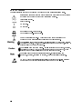
Safety Summary
When you notice any of the unusual conditions listed below, immediately
terminate operation and disconnect the power cable.
Contact your local Agilent Technologies sales representative or
authorized service company for repair of the instrument. If you continue
to operate without repairing the instrument, there is a potential fire or
shock hazard for the operator.
n Instrument operates abnormally.
n Instrument emits abnormal noise, smell, smoke or a spark-like light
during the operation.
n Instrument generates high temperature or electrical shock during
operation.
n Power cable, plug, or receptacle on instrument is damaged.
n Foreign substance or liquid has fallen into the instrument.
Caution
Do not exceed the operating input power, voltage, and current
level and signal type appropriate for the instrument being used, refer to
your instrument's Function Reference.
Electrostatic discharge(ESD) can damage the highly sensitive
microcircuits in your instrument. ESD damage is most likely to occur as
the test fixtures or cables are being connected or disconnected. Protect
them from ESD damage by wearing a grounding strap that provides a
high resistance path to ground. Alternatively, ground yourself to
discharge any static charge built-up by touching the outer shell of any
grounded instrument chassis before touching the test port connectors.
The measurement input terminal "RF-IN" is vulnerable to ESD.
Attaching the power limitter to the terminal can effectively minimize
ESD damage which may occur in your instrument.
43521A
Agilent 43521A Downconverter Unit
Operation Manual
Agilent Part No. 43521-90010
Printed in JAPAN July 2003
Fourth Edition
Notice
The information contained in this document is subject to change without notice.
This document contains proprietary information that is protected by copyright. All rights are
reserved. No part of this document may be photocopied, reproduced, or translated to another
language without the prior written consent of the Agilent Technologies Japan, Ltd.
Agilent Technologies Japan, Ltd.
Component Test PGU-Kobe
1-3-2, Murotani, Nishi-ku, Kobe-shi,
Hyogo, 651-2241 Japan
c Copyright 1999, 2002, 2003 Agilent Technologies Japan, Ltd.
Manual Printing History
The manual's printing date and part number indicate its current edition. The printing date
changes when a new edition is printed. (Minor corrections and updates that are incorporated
at reprint do not cause the date to change.) The manual part number changes when extensive
technical changes are incorporated.
July 1999
First Edition (part number: 43521-90000)
December 1999
Second Edition (part number: 43521-90000)
September 2002
Third Edition (part number: 43521-90000)
July 2003
Fourth Edition (part number: 43521-90010)
:::::::::::::::::::::::::::::::::::::::::::::
::::::::::::::::::::::::::::::::::::
:::::::::::::::::::::::::::::::::::::
::::::::::::::::::::::::::::::::::::::::::
iii
Safety Summary
The following general safety precautions must be observed during all phases of operation,
service, and repair of this instrument. Failure to comply with these precautions or with specic
WARNINGS elsewhere in this manual may impair the protection provided by the equipment.
In addition it violates safety standards of design, manufacture, and intended use of the
instrument.
The Agilent Technologies assumes no liability for the customer's failure to comply with these
requirements.
Note
43521A complies with INSTALLATION CATEGORY II and POLLUTION DEGREE
2 in IEC61010-1. 43521A is an INDOOR USE product.
Note
LEDs in 43521A are Class 1 in accordance with IEC60825-1.
CLASS 1 LED PRODUCT
Ground The Instrument
To avoid electric shock hazard, the instrument chassis and cabinet must be connected to a
safety earth ground by the supplied power cable with earth blade.
DO NOT Operate In An Explosive Atmosphere
Do not operate the instrument in the presence of ammable gasses or fumes. Operation of any
electrical instrument in such an environment constitutes a denite safety hazard.
Keep Away From Live Circuits
Operating personnel must not remove instrument covers. Component replacement and internal
adjustments must be made by qualied maintenance personnel. Do not replace components
with the power cable connected. Under certain conditions, dangerous voltages may exist even
with the power cable removed. To avoid injuries, always disconnect power and discharge
circuits before touching them.
DO NOT Service Or Adjust Alone
Do not attempt internal service or adjustment unless another person, capable of rendering rst
aid and resuscitation, is present.
DO NOT Substitute Parts Or Modify Instrument
Because of the danger of introducing additional hazards, do not install substitute parts or
perform unauthorized modications to the instrument. Return the instrument to a Agilent
Technologies Sales and Service Oce for service and repair to ensure that safety features are
maintained.
iv
Dangerous Procedure Warnings
Warnings , such as the example below, precede potentially dangerous procedures throughout
this manual. Instructions contained in the warnings must be followed.
Warning
Dangerous voltages, capable of causing death, are present in this
instrument. Use extreme caution when handling, testing, and adjusting
this instrument.
v
Typeface Conventions
Bold
Italics
Computer
4HARDKEYS5
NNNNNNNNNNNNNNNNNNNNNNNNNN
SOFTKEYS
vi
Boldface type is used when a term is dened. For example: icons are
symbols.
Italic type is used for emphasis and for titles of manuals and other
publications.
Italic type is also used for keyboard entries when a name or a variable
must be typed in place of the words in italics. For example: copy
lename means to type the word copy, to type a space, and then to
type the name of a le such as file1.
Computer font is used for on-screen prompts and messages.
Labeled keys on the instrument front panel are enclosed in 4 5.
Softkeys located to the right of the LCD are enclosed in .
NNNNN
Certication
Agilent Technologies certies that this product met its published specications at the time
of shipment from the factory. Agilent Technologies further certies that its calibration
measurements are traceable to the United States National Institute of Standards and
Technology, to the extent allowed by the Institution's calibration facility, or to the calibration
facilities of other International Standards Organization members.
Documentation Warranty
The material contained in this document is provided \as is," and is subject to being changed,
without notice, in future editions. Further, to the maximum extent permitted by applicable
law, Agilent disclaims all warranties, either express or implied with regard to this manual
and any information contained herein, including but not limited to the implied warranties of
merchantability and tness for a particular purpose. Agilent shall not be liable for errors or for
incidental or consequential damages in connection with the furnishing, use, or performance
of this document or any information contained herein. Should Agilent and the user have a
separate written agreement with warranty terms covering the material in this document that
conict with these terms, the warranty terms in the separate agreement will control.
Exclusive Remedies
The remedies provided herein are buyer's sole and exclusive remedies. Agilent Technologies
shall not be liable for any direct, indirect, special, incidental, or consequential damages,
whether based on contract, tort, or any other legal theory.
Assistance
Product maintenance agreements and other customer assistance agreements are available for
Agilent Technologies products.
For any assistance, contact your nearest Agilent Technologies Sales and Service Oce.
Addresses are provided at the back of this manual.
vii
Safety Symbols
General denitions of safety symbols used on equipment or in manuals are listed below.
Instruction manual symbol: the product is marked with this symbol when it is
necessary for the user to refer to the instruction manual.
Alternating current.
Direct current.
On (Supply).
O (Supply).
In position of push-button switch.
Out position of push-button switch.
Frame (or chassis) terminal. A connection to the frame (chassis) of the
equipment which normally include all exposed metal structures.
This Warning sign denotes a hazard. It calls attention to a procedure, practice,
condition or the like, which, if not correctly performed or adhered to, could
result in injury or death to personnel.
This Caution sign denotes a hazard. It calls attention to a procedure, practice,
condition or the like, which, if not correctly performed or adhered to, could
result in damage to or destruction of part or all of the product.
This Note sigh denotes important information. It calls attention to a
procedure, practice, condition or the like, which is essential to highlight.
Axed to product containing static sensitive devices use anti-static handling
procedures to prevent electrostatic discharge damage to component.
viii
Contents
1. Unpacking and Checking the Contents of the Shipment
Incoming Inspection . . . . . . . . . . . . . . . . . . . . . . . . . . . . .
Contents of the Shipment . . . . . . . . . . . . . . . . . . . . . . . . . .
2. Connecting 43521A
Notes on Installation . . . . . . . . . . . . . . . . . .
Requirements for Operating Environment . . . . . . .
Providing clearance to dissipate heat at installation site
Instruction for Cleaning . . . . . . . . . . . . . . .
Connection to the 4352B and External Signal Source . . .
Connections on the Front Panel . . . . . . . . . . . .
Connections on the Rear Panel . . . . . . . . . . . .
Power Requirements . . . . . . . . . . . . . . . . . .
Ratings of the Power Source . . . . . . . . . . . . .
Power Cable . . . . . . . . . . . . . . . . . . . . .
3. Front Panel and Rear Panel
Front Panel . . . . . . . . . .
1. RF Input Connector . . . .
2. RF Output Connector . . .
3. LO Output Connector . . .
4. LO Input Connector . . . .
5. Line Switch . . . . . . . .
Rear Panel . . . . . . . . . .
1. 40 MHz Input Terminal . .
2. I/O Port . . . . . . . . .
3. Inlet . . . . . . . . . . .
4. 600 MHz Adjustment Knob
Replacing the Fuse . . . .
Replacing the Fuse . . . . . .
.
.
.
.
.
.
.
.
.
.
.
.
.
.
.
.
.
.
.
.
.
.
.
.
.
.
.
.
.
.
.
.
.
.
.
.
.
.
.
.
.
.
.
.
.
.
.
.
.
.
.
.
1-1
1-1
.
.
.
.
.
.
.
.
.
.
.
.
.
.
.
.
.
.
.
.
.
.
.
.
.
.
.
.
.
.
.
.
.
.
.
.
.
.
.
.
.
.
.
.
.
.
.
.
.
.
.
.
.
.
.
.
.
.
.
.
.
.
.
.
.
.
.
.
.
.
.
.
.
.
.
.
.
.
.
.
.
.
.
.
.
.
.
.
.
.
.
.
.
.
.
.
.
.
.
.
.
.
.
.
.
.
.
.
.
.
2-1
2-1
2-1
2-2
2-2
2-3
2-4
2-5
2-5
2-5
.
.
.
.
.
.
.
.
.
.
.
.
.
.
.
.
.
.
.
.
.
.
.
.
.
.
.
.
.
.
.
.
.
.
.
.
.
.
.
.
.
.
.
.
.
.
.
.
.
.
.
.
.
.
.
.
.
.
.
.
.
.
.
.
.
.
.
.
.
.
.
.
.
.
.
.
.
.
.
.
.
.
.
.
.
.
.
.
.
.
.
.
.
.
.
.
.
.
.
.
.
.
.
.
.
.
.
.
.
.
.
.
.
.
.
.
.
.
.
.
.
.
.
.
.
.
.
.
.
.
.
.
.
.
.
.
.
.
.
.
.
.
.
.
.
.
.
.
.
.
.
.
.
.
.
.
.
.
.
.
.
.
.
.
.
.
.
.
.
.
.
.
.
.
.
.
.
.
.
.
.
.
.
.
.
.
.
.
.
.
.
.
.
.
.
.
.
.
.
.
.
.
.
.
.
.
.
.
.
.
.
.
.
.
.
.
.
.
.
.
.
.
.
.
.
.
.
.
.
.
.
.
.
.
.
.
.
.
.
.
.
.
.
.
.
.
.
3-1
3-2
3-2
3-2
3-2
3-2
3-3
3-3
3-3
3-3
3-3
3-4
3-4
Rack/Handle Installation . . . . . . . . .
Option 1CN Handle Kit . . . . . . . . .
Installing the Handle . . . . . . . . .
Option 1CM Rack Mount Kit . . . . . .
Mounting into the Rack . . . . . . .
Option 1CP Rack Mount & Handle Kit . .
Mounting into the Rack (with Handles)
.
.
.
.
.
.
.
.
.
.
.
.
.
.
.
.
.
.
.
.
.
.
.
.
.
.
.
.
.
.
.
.
.
.
.
.
.
.
.
.
.
.
.
.
.
.
.
.
.
.
.
.
.
.
.
.
.
.
.
.
.
.
.
.
.
.
.
.
.
.
.
.
.
.
.
.
.
.
.
.
.
.
.
.
.
.
.
.
.
.
.
.
.
.
.
.
.
.
.
.
.
.
.
.
.
.
.
.
.
.
.
.
.
.
.
.
.
.
.
.
.
.
.
.
.
.
4-1
4-2
4-2
4-2
4-2
4-2
4-2
4. Rack/Handle Installation
Contents-1
5. Specications
Specications of the 43521A . . . . . . . . . . . . . . . . . . . . . . . .
RF Power Measurement . . . . . . . . . . . . . . . . . . . . . . . . .
Operating Environment . . . . . . . . . . . . . . . . . . . . . . . .
Non-Operating Environment . . . . . . . . . . . . . . . . . . . . . .
Others . . . . . . . . . . . . . . . . . . . . . . . . . . . . . . . .
System Specications . . . . . . . . . . . . . . . . . . . . . . . . . . .
1. When Frequency Band is 10 MHz to 3 GHz . . . . . . . . . . . . . . . .
RF Power Measurement (common to the tester mode and the analyzer mode)
2. When Frequency Band is other than 10 MHz to 3 GHz . . . . . . . . . . .
2-1. Tester Mode . . . . . . . . . . . . . . . . . . . . . . . . . . . . .
RF Power Measurement . . . . . . . . . . . . . . . . . . . . . . . .
Frequency Measurement . . . . . . . . . . . . . . . . . . . . . . . .
FM Deviation Measurement . . . . . . . . . . . . . . . . . . . . . .
C/N Ratio Measurement . . . . . . . . . . . . . . . . . . . . . . . .
2-2. Analyzer Mode . . . . . . . . . . . . . . . . . . . . . . . . . . .
RF Power Characteristics vs. DC Control Voltage Measurement . . . . . .
Frequency/Tuning Sensitivity Characteristics vs. DC Control Voltage
Measurement . . . . . . . . . . . . . . . . . . . . . . . . . . . .
Phase Noise Characteristics vs. Oset Frequency Measurement . . . . . .
Frequency Transient Measurement . . . . . . . . . . . . . . . . . . .
Spectrum Measurement . . . . . . . . . . . . . . . . . . . . . . . .
.
.
.
.
.
.
.
.
.
.
.
.
.
.
.
.
5-1
5-1
5-2
5-2
5-2
5-3
5-3
5-3
5-3
5-3
5-3
5-3
5-3
5-3
5-4
5-4
.
.
.
.
5-4
5-4
5-4
5-4
Introduction . . . . . . . . . . . . . . . . . . . . . . . . . . . . . . . . .
Manual Changes . . . . . . . . . . . . . . . . . . . . . . . . . . . . . . .
Serial Number . . . . . . . . . . . . . . . . . . . . . . . . . . . . . . . .
A-1
A-1
A-2
A. Manual Changes
Contents-2
Figures
2-1.
2-2.
2-3.
3-1.
3-2.
4-1.
A-1.
Connections on the Front Panel .
Connections on the Rear Panel .
Optional Power Cables . . . . .
Front Panel . . . . . . . . . .
rear panel . . . . . . . . . . .
Rack Mount Kit Installation . .
Serial Number Plate . . . . . .
.
.
.
.
.
.
.
.
.
.
.
.
.
.
.
.
.
.
.
.
.
.
.
.
.
.
.
.
.
.
.
.
.
.
.
.
.
.
.
.
.
.
.
.
.
.
.
.
.
.
.
.
.
.
.
.
.
.
.
.
.
.
.
.
.
.
.
.
.
.
.
.
.
.
.
.
.
.
.
.
.
.
.
.
.
.
.
.
.
.
.
.
.
.
.
.
.
.
.
.
.
.
.
.
.
.
.
.
.
.
.
.
.
.
.
.
.
.
.
.
.
.
.
.
.
.
.
.
.
.
.
.
.
.
.
.
.
.
.
.
.
.
.
.
.
.
.
.
.
.
.
.
.
.
2-3
2-4
2-6
3-1
3-3
4-1
A-2
List of the Contents of the Shipment
Parts Used on the Front Panel . . .
Parts Used on the Rear Panel . . . .
Rating of Fuse . . . . . . . . . . .
Rack Mount Kits . . . . . . . . . .
RF Power Measurement Accuracy . .
Noise Floor of Phase Noise . . . . .
Manual Changes by Serial Number .
.
.
.
.
.
.
.
.
.
.
.
.
.
.
.
.
.
.
.
.
.
.
.
.
.
.
.
.
.
.
.
.
.
.
.
.
.
.
.
.
.
.
.
.
.
.
.
.
.
.
.
.
.
.
.
.
.
.
.
.
.
.
.
.
.
.
.
.
.
.
.
.
.
.
.
.
.
.
.
.
.
.
.
.
.
.
.
.
.
.
.
.
.
.
.
.
.
.
.
.
.
.
.
.
.
.
.
.
.
.
.
.
.
.
.
.
.
.
.
.
.
.
.
.
.
.
.
.
.
.
.
.
.
.
.
.
.
.
.
.
.
.
.
.
.
.
.
.
.
.
.
.
.
.
.
.
.
.
.
.
1-1
2-3
2-4
3-4
4-1
5-1
5-4
A-1
Tables
1-1.
2-1.
2-2.
3-1.
4-1.
5-1.
5-2.
A-1.
Contents-3
Unpacking and Checking the Contents of the
Shipment
1
This chapter describes how to check the shipping container of your 43521A (
Downconverter Unit), the appearance of the product, and the contents of the shipment.
Incoming Inspection
When you receive the product, inspect the shipping container for damage. If the shipping
container or cushioning material is damaged, it should be kept until the contents of the
shipment have been checked for completeness and the 43521A has been checked mechanically
and electrically. The contents of the shipment should be as listed in Table 1-1. If the contents
are incomplete, if there is mechanical damage or defect, notify the nearest Agilent Technologies
sales oce. If the shipping container is damaged, or the cushioning material shows signs of
unusual stress, notify the carrier as well as the Agilent Technologies oce. Keep the shipping
materials for the carrier's inspection.
Warning
To avoid hazardous electrical shock, do not turn on the 43521A when
there are signs of shipping damage to any portion of the outer enclosure
(for example, covers, panel, or display).
Contents of the Shipment
The 43521A (Downconverter Unit) includes the following items. Check to see that the contents
are complete. If not, contact your nearest Agilent Technologies Sales and Service Oce.
Table 1-1. List of the Contents of the Shipment
Name
Downconverter Unit
BNC cable (30 cm x 1)
N-N cable (18 cm x 2)
N-N cable (50 cm x 1)
15-pin D-Sub cable
CD-ROM (for manuals)1
Power cable
43521A Operation Manual (Option ABA only)
Agilent Part Number
43521A
8120-1838
8120-4387
43521-61638
04380-61601
43521-9050x2
8120-4753
43521-900x02
1 CD-ROM contains the contents of the Operation Manual.
2 The number indicated by \x" in the part number is allocated for numbers increased by one each time a
revision is made. The latest edition comes with the product.
Unpacking and Checking the Contents of the Shipment
1-1
2
Connecting 43521A
The 43521A (Downconverter Unit) is used as part of the 4352S (VCO/PLL Signal Test System).
Using the 43521A expands the maximum frequency of the 4352S to 12.6 GHz. This chapter
describes how to make connection for the 4352S when associated with the 43521A.
How to use the entire 4352S including the 43521A is described in Chapter 5 of the 4352B
Function Reference, while a quick guide to diagnosis is provided in Appendix F of that
document. For related sample programs, see \Frequency Transient Measurement" in Chapter
12 of the 4352B GPIB Programming Manual. After the completion of the connection for the
4352S, proceed to the reference.
Note that the 4352B with the rmware of Rev 2.00 or greater is required in order to operate
the 43521A.
Notes on Installation
Requirements for Operating Environment
The requirements for the operating environment of the 43521A is the same as those of the
4352B. Use it under the environment shown below.
Temerature: 0 C to 40 C
Humidity:
Relative humidity of 95% or less (at 40 C)
Note
The 43521A must be protected from temperature extremes which could cause
condensation within the instrument.
Providing clearance to dissipate heat at installation site
To ensure the specications and measurement accuracy of the product, you must keep ambient
temperature around the product within the specied range by providing appropriate cooling
clearance around the product or, for the rackmount type, by forcefully air-cooling inside
the rack housing. For information on ambient temperature to satisfy the specications and
measurement accuracy of the product, refer to \Specications" in Chapter 5.
When the ambient temperature around the product is kept within the temperature range
of the operating environment specication (refer to \Operating Environment" in Chapter
5), the product conforms to the requirements of the safety standard. Furthermore, under
that temperature environment, it has been conrmed that the product still conforms to the
requirements of the safety standard when it is enclosed with cooling clearance as follows:
Connecting 43521A 2-1
Conditions
Rear
180 mm
Side
60 mm
Instruction for Cleaning
To prevent electrical shock, disconnect the 43521A's power cable from the power outlet before
cleaning. To clean the exterior of the 43521A, wipe the surfaces with a dry cloth or a soft cloth
that is soaked with water and wrung tightly, without undue pressure. Do not attempt to clean
the 43521A internally.
Connection to the 4352B and External Signal Source
The 43521A is used by connecting it to the 4352B (VCO/PLL Signal Analyzer) and the external
signal source. To operate the 43521A, the 4352B with the rmware of Rev 2.00 or greater
is required. All parts required for the connection including cables and connectors will come
with the 43521A and the 4352B. For the information on the accessories of the 4352B, refer to
Chapter 3 of the 4352B Function Reference.
2-2 Connecting 43521A
Connections on the Front Panel
Make connections as shown in Figure 2-1. For how to connect a DUT (Device Under Test), refer
to Chapter 5 of the 4352B Function Reference.
Figure 2-1. Connections on the Front Panel
No.
Name
1 N-N cable
(18 cm x 2)
2 N-N cable
Table 2-1. Parts Used on the Front Panel
Connection Locations
Agilent Part Number
8120-4387
41951-61602
(accessory of the
4352B)
The RF IN connector of the 4352B and
the RF OUT connector of the 43521A,
the LO IN connector of the 4352B and
the LO OUT connector of the 43521A
The FR output connector of the external
signal generator and the LO IN
connector of the 43521A
Connecting 43521A 2-3
Connections on the Rear Panel
Make connections as shown in Figure 2-2.
Figure 2-2. Connections on the Rear Panel
No.
Name
1 BNC-BNC connector
Table 2-2. Parts Used on the Rear Panel
Connection Locations
Agilent Part Number
2 BNC-BNC cable
1250-1859
(accessory of the
4352B)
8120-1838
3 15-pin D-Sub cable
04380-61601
4 BNC-BNC cable
8120-1839
(accessory of the
4352B)
10833A
(accessory of the
4352B)
(30 cm)
(60 cm)
5 GPIB cable
2-4 Connecting 43521A
The 2ND IF Output connector and the
2ND IF Input connector of the 4352B
The 40MHz Output connector of the
4352B and the 40MHz Input connector
of the 43521A
The I/O PORT connector of the 4352B
and the I/O PORT connector of the
43521A
The EXT REF Input connector of the
4352B and the 10MHz OUT connector of
the external signal generator
The GPIB connector of the 4352B and
the GPIB connector of the external
signal generator
Power Requirements
Ratings of the Power Source
The 43521A requires the following power source:
Voltage : 90 to 132 Vac or 198 to 264 Vac
Frequency : 47 to 63 Hz
Power : 100 VA maximum
Power Cable
In accordance with international safety standards, this instrument is equipped with a
three-wire power cable. When connected to an appropriate ac power outlet, this cable grounds
the instrument frame.
The type of power cable shipped with each instrument depends on the country of destination.
Refer to Figure 2-3 for the part numbers of the power cables available.
Warning
For protection from electrical shock, the power cable ground must not be
defeated.
The power plug must be plugged into an outlet that provides a protective
earth ground connection.
Connecting 43521A 2-5
Figure 2-3. Optional Power Cables
2-6 Connecting 43521A
3
Front Panel and Rear Panel
This chapter explains the front and rear panels of the 43521A (Downconverter Unit).
How to use the entire 4352S including the 43521A is described in Chapter 5 of the
4352B Function Reference. Related sample programs are found in \Frequency Transient
Measurement" in Chapter 12 of the 4352B GPIB Programming Manual.
Front Panel
Figure 3-1 shows the conguration of the front panel.
Figure 3-1. Front Panel
Front Panel and Rear Panel 3-1
1. RF Input Connector
Receives the RF output signal from the device under test (signal to be measured).
INSTALLATOIN CATEGORY I
2. RF Output Connector
The RF signal (signal to be measured) inputted to the RF input connector is outputted from this
connector, and sent to the RF input connector of the 4352B (VCO/PLL Signal Analyzer) through
the N-N cable. When the frequency band setting of this test system is 10 MHz to 3 GHz, the
signal inputted to the RF input connector is outputted from this connector as it is. When the
frequency band setting is not 10 MHz to 3 GHz, it is converted to an IF frequency signal and
then outputted.
3. LO Output Connector
The signal from this connector is sent to the LO IN connector of the 4352B (
VCO/PLL Signal Analyzer) through the N-N cable. The signal outputted from this connector
is as follows: if the frequency band setting of this test system is 10 MHz to 3 GHz, the signal
inputted to the LO input connector is outputted; if it is outside of 10 MHz to 3 GHz, the signal
from the internal oscillator of the 43521A (600 MHz) is outputted.
4. LO Input Connector
Receives the output signal from the external signal generator.
5. Line Switch
Toggles on/o the power each time the button is pressed. j and indicate ON and OFF,
respectively. When the switch is ON, the right lamp is lit in green.
3-2 Front Panel and Rear Panel
Rear Panel
Figure 3-2 shows the conguration of the rear panel.
Figure 3-2. rear panel
1. 40 MHz Input Terminal
To improve the frequency accuracy of the 600-MHz signal inside the 43521A, the 40-MHz signal
from the rear panel of the 4352B (VCO/PLL Signal Analyzer) is inputted to this connector to
provide phase locking for synchronizing the 600-MHz signal to the 40-MHz signal.
2. I/O Port
Receives the digital signal from the I/O port connector on the rear panel of the 4352B. All
operations of the 43521A are controlled by this signal.
3. Inlet
Connects the power cable to this inlet. To replace the fuse, please see \Replacing the Fuse" in
this chapter.
4. 600 MHz Adjustment Knob
Adjusts the frequency of the 600-MHz signal outputted from the LO output connector. For
usual use, adjustment is not required. It is required only at periodical calibration of the
43521A. For details, refer to the 43521A Service Manual.
Front Panel and Rear Panel 3-3
Replacing the Fuse
Select a proper fuse according to the Table 3-1.
Table 3-1. Rating of Fuse
Rating Part Number
3A 250Vac
UL/CSA type
Time delay
2110-0381
For ordering the fuse, contact your nearest Agilent Technologies Sales and Service Oce.
Replacing the Fuse
Lever a small minus screwdriver
to dismount the fuse holder next
to the AC line receptacle on the
rear panel.
Caution
Replace the fuse in the fuse
holder.
When replacing the fuse, be sure to check that the rating and the type are
correct. Do not use a repaired fuse or short-circuited fuse holder.
3-4 Front Panel and Rear Panel
4
Rack/Handle Installation
Rack/Handle Installation
This instrument can be rack-mounted and used as a component in a measurement system.
Figure 4-1 shows how to rack-mount the instrument.
Option
Table 4-1. Rack Mount Kits
Description
1CN
1CM
1CP
Front Handle Kit
Rack Mount Kit
Rack Mount & Handle Kit
Agilent Part
Number
5063-9226
5063-9212
5063-9219
Figure 4-1. Rack Mount Kit Installation
Rack/Handle Installation
4-1
Option 1CN Handle Kit
Option 1CN includes a pair of handles and accessories to attach them to the instrument.
Installing the Handle
1. Remove the cosmetic panels 1 axed to both sides of the frame on the front panel. (See
Figure 4-1.)
2. Attach the handles 3 to both sides of the instrument using the screws provided.
3. Attach the trim strips 4 to the handles.
Option 1CM Rack Mount Kit
Option 1CM includes a pair of anges and accessories to mount the instrument to an
EIA-compliant standard rack (482.6 mm wide).
Mounting into the Rack
1. Remove the cosmetic panels 1 axed to both sides of the frame on the front panel. (See
Figure 4-1.)
2. Attach the anges 2 to both sides of the instrument using the screws provided.
3. Remove all the four feet. (Lift the tab and slide the foot in the arrow direction.)
4. Mount the instrument into the rack.
Option 1CP Rack Mount & Handle Kit
Option 1CP includes a pair of anges, handles, and accessories.
Mounting into the Rack (with Handles)
1. Remove the cosmetic panels 1 axed to both sides of the frame on the front panel. (See
Figure 4-1.)
2. Attach the handles 3 and the anges 5 to both sides of the instrument using the screws
provided.
3. Remove all the four feet. (Lift the tab and slide the foot in the arrow direction.)
4. Mount the instrument into the rack.
4-2 Rack/Handle Installation
5
Specications
The specications mean the performance standards and operation limits. They are the
43521A's performance guaranteed, unless otherwise specied, over the temperature range
of 0 C to 40 C and after a warm-up time of at least 30 minutes has elapsed from power-on.
Information provided as typical, reference, or approximate, though not specications, is
intended to serve as reference data for ecient operation of the 43521A.
Specications of the 43521A
RF Power Measurement
Frequency band
VSWR
Input level
::::::::::::::::::::::::::::::::::::::::::::::::::::::::::
2.4 GHz to 12.6 GHz
1.5
:::::::::::::::::::::::::::::::::::::::::::::::::::::::::::::::::::::::::::::::::::::::<
When the input attenuator is 0 dB:
When the input attenuator is 0 dB:
020 dBm to 0 dBm
020 dBm to +20 dBm
:::::::::::::::::::::::::::::::::::::::
Resolution
Measurement accuracy
>
::::::::::::::::::::::::::::::::::
0.01 dB
Table 5-1
::::::::::::::::::::::::::::::::::::::::::::::::::::::::::::::::::::::::::::::
:::::::::::::::::::::::::::::::::::::::::::::::::::::::::::::::
Table 5-1. RF Power Measurement Accuracy
Temperature Range
Level of Input Signal
0 to 40 C
23610 C
2.4 GHz to 8 GHz 62.0 dB
2.4 GHz to 4 GHz 61.5dB
-20 dBm to 0 dBm
8 GHz to 12.6 GHz 62.5 dB
4 GHz to 8 GHz 62.0 dB
(ATT=0dB)
8 GHz to 12.6 GHz 62.5 dB
2.4 GHz to 4 GHz 61.5 dB
15 dBm
(Same as left)
4 GHz to 8 GHz 62.0 dB
(ATT 0 dB)
8 GHz to 12.6 GHz 62.5 dB
2.4 GHz to 4 GHz 61.5 dB
20 dBm
>
(ATT 0 dB)
>
(Reference)
4 GHz to 8 GHz 62.0 dB
(Reference)
8 GHz to 12.6 GHz 62.5 dB
(Reference)
(Same as left)
* Peak voltage response
* The above specications are applicable when the 43521A is controlled by the 4352B and the
measurement result is displayed on the 4352B.
@6 GHz,-5 dBm,23610 C
@12 GHz,-5 dBm,23610 C
::::::::::::::::::::::::::::::::::::::::::::::::::::::
:::::::::::::::::::::::::::::::::::::::::::::::::::::
60.8 dB(Typical)
61.0 dB(Typical)
Specications 5-1
Operating Environment
Temperature
Humidity
Altitude
Warm up time
0 C to 40 C
15% to 95% RH
0 to 2000 m
30 minutes
:::::::::::::::::::::::::::::::::::::::::::::::::::::::::::::::::::::::
:::::::::::::::::::::::::::::::::::::::::::::::::::::::::::::::::::::::
::::::::::::::::::::::::::::::::::::::::::::::::::::::::::::::::::::::::::::
:::::::::::::::::::::::::::::::::::::::::::::::::::::::::::::::::::::::
Non-Operating Environment
Temperature
Humidity
::::::::::::::::::::::::::::::::::::::::::::::::::::::::::::::::::::
:::::::::::::::::::::::::::::::::::::::::::::::::::::::::::::::::::::::
@wet bulb temperature 45 C, without condensation
Altitude
15% to 95% RH
::::::::::::::::::::::::::::::::::::::::::::::::::::::::::::::::::::::::::::
Others
EMC
020 C to 60 C
::::::::::::::::::::::::::::::::::::::::::::::::::::::::::::
Emission: EN 55011:1991 / CISPR 11:1990 Group 1, Class A
Immunity: EN 50082-1:1992
0 to 4572 m
Complies with those standards
EN/IEC 61000-3-2 1995
EN/IEC 61000-3-3 1995
EN/IEC 61000-4-2:1995 4 kV CD / 8 kV AD
EN/IEC 61000-4-3:1995 3 V/m, 27-1000 MHz, 80 % AM
EN/IEC 61000-4-4:1995 Main 1 kV / Signal 0.5kV
EN/IEC 61000-4-5:1995 Common 2 kV / Normal 1 kV
EN/IEC 61000-4-6:1996 3 V, 0.15-80 MHz, Main
This ISM device complies with Canadian ICES-001.
Cet appareil ISM est conforme a la norme NMB-001 du Canada.
Safety
:::::::::
A2(1995)
Complies with EN61010-1(1993) + A2(1995)/IEC 61010-1(1990) + A1(1992) +
Power requirements
Weight
Dimensions
RF input terminal (Reference)
:::::::::::::
Complies with CSA C22.2 No.1010.1-92
90 V to 132 V, or 198 V to 264 V, 47 to 63 Hz, 100 VA max
8 kg max
425(W) 2 101(H) 2 553(D) mm
:::::::::::::::::::::::::::::::::::::::::::::::::::::::::::::::::::::::::::::::::
:::::::::::::::::::::::::::::::::::::::::::::::::::::
Heterodyne path gain
Insertion Loss in Direct Path:
::::::::::::::::::::::::::::::::::::::::::::::::::::::::::
::::::::::::::::::::::::::::::::::::::::::::::::::
LO input terminal (Reference)
Input level
Frequency range
Insertion Loss in Direct Path:
20 dB @ 6 GHz
0.5dB @ 3 GHz
+10 dBm
10 MHz to 6 GHz
0.5dB @ 3 GHz
:::::::::::::::::::::::::::::::::::::::::::::::::::::::::::::::::::::::::::
:::::::::::::::::::::::::::::::::::::::::::::::::::::::::::::
::::::::::::::::::::::::::::::::::::::::::::::::::
LO output terminal (Reference)
600 MHz Output Level
600 MHz Frequency Accuracy
+8 dBm
600 MHz 6 50 ppm
::::::::::::::::::::::::::::::::::::::::::::::::::::::::::::::
5-2 Specications
:::::::::::::::::::::::::::::::::::::::::::::
System Specications
The following provide the specications of the system in which the 43521A is connected to
the 4352B (VCO/PLL Signal Analyzer) and the external signal source. It is assumed that the
43521A is locked by the 40 MHz signal from the 4352B. All values, except for the RF power
measurement in 2-1. Tester Mode, are reference values. Note that same specications as those
of the 4352B are not shown.
1. When Frequency Band is 10 MHz to 3 GHz
RF Power Measurement (common to the tester mode and the analyzer
mode)
Measurement accuracy
When the frequency 2 GHz
Add 60.1 dB to the accuracy of the 4352B.
When the frequency is 2 GHz to 3 GHz
Add 60.2 dB to the accuracy of the 4352B.
The same specications as the 4352B are applicable for other measurement parameters.
::::::::::::::::::::
::::::::::
2. When Frequency Band is other than 10 MHz to 3 GHz
2-1. Tester Mode
RF Power Measurement
Same as the specications of the 43521A.
Frequency Measurement
Frequency band
Resolution
Measurement accuracy
:::::::::::::::::::::::::::::::::::::::::::::::::::::::::::
2.4 GHz to 12.6 GHz
Same as the 4352B.
Same as the 4352B.
::::::::::::::::::::::::::::::::::::::::::::::::::::::::::::::::::
::::::::::::::::::::::::::::::::::::::::::::::::::::
FM Deviation Measurement
Measurement range
Deviation resolution
Deviation measurement accuracy
Residual FM
::::::::::::::::::::::::::::::::::::::::::::::::::::::::
:::::::::::::::::::::::::::::::::::::::::::::::::::::::
::::::::::::::::::::::::::::::::::::::::
::::::::::::::::::::::::::::::::::::::::::::::::::::::::::::::::
Same as the 4352B.
Same as the 4352B.
Same as the 4352B.
Same as the 4352B.
C/N Ratio Measurement
Oset frequency range
Phase noise
Same as the 4352B.
Table 5-2
The table is applicable when the 8665B (with Option 004) is used as the external signal
source. If the external signal source is the 8664A (with Option 004), use values of up to 6
GHz; if it is the 8665A (with Option 004), use values of up to 9 GHz.
::::::::::::::::::::::::::::::::::::::::::::::::::::
:::::::::::::::::::::::::::::::::::::::::::::::::::::::::::::::::::::::::::
Specications 5-3
Table 5-2. Noise Floor of Phase Noise
Oset Freq (Hz) 100 300 600 1k 3k 6k 10k 30k 60k 100k 300k 600k 1M 3M 6M 9M
RF Freq 3 GHz -68 -75 -85 -93 -111 -120 -125 -132 -135 -137 -145 -149 -150 -151 -151 -151
6 GHz -63 -68 -79 -88 -106 -115 -119 -126 -129 -131 -139 -144 -147 -149 -150 -150
9 GHz -57 -65 -76 -84 -101 -109 -114 -120 -123 -125 -133 -139 -143 -145 -145 -146
12 GHz -58 -63 -73 -81 -99 -108 -113 -120 -123 -125 -134 -138 -142 -145 -147 -147
Measurement accuracy
::::::::::::::::::::::::::::::::::::::::::::::::::::
Same as the 4352B.
2-2. Analyzer Mode
RF Power Characteristics vs. DC Control Voltage Measurement
Same as the RF Power Measurement in the 43521A.
Frequency/Tuning Sensitivity Characteristics vs. DC Control Voltage
Measurement
Same as the frequency measurement in the tester mode.
Phase Noise Characteristics vs. Oset Frequency Measurement
Same as the C/N ratio measurement in the tester mode.
Frequency Transient Measurement
Frequency accuracy
Frequency span
Measurement resolution
Same as the 4352B.
2 MHz, 20 MHz, 512 MHz (MAX)
50 Hz, 500 Hz, 12.8 kHz (MAX)
:::::::::::::::::::::::::::::::::::::::::::::::::::::::
:::::::::::::::::::::::::::::::::::::::::::::::
::::::::::::::::::::::::::::::::::::::
Spectrum Measurement
When the detection mode is specied to positive peak
Absolute level accuracy
For @010 dBm input, attenuator = 10 dB,
Relative level accuracy
:::::::::::::::::::::::::::::::::::::::::::
::::::::::::::::::::::::::::::::::::::::::::::::::::
5-4 Specications
63dBm
Same as the 4352B.
A
Manual Changes
Introduction
This appendix contains the information required to adapt this manual to earlier versions or
congurations of the 43521A than the current printing date of this manual. The information in
this manual applies directly to the 43521A serial number prex listed on the title page of this
manual.
Manual Changes
To adapt this manual to your 43521A see Table A-1 and make all the manual changes listed
opposite your instrument's serial number and rmware version.
Instruments manufactured after the printing of this manual may be dierent from those
documented in this manual. Later instrument versions will be documented in a manual changes
supplement that will accompany the manual shipped with that instrument.
If your instrument's serial number is not listed on the title page of this manual or in Table A-1,
it may be documented in a yellow MANUAL CHANGES supplement.
In additions to change information, the supplement may contain information for correcting
errors (Errata) in the manual. To keep this manual as current and accurate as possible,
Agilent Technologies recommends that you periodically request the latest MANUAL CHANGES
supplement.
For information concerning serial number prexes not listed on the title page or in the
MANUAL CHANGE supplement, contact the nearest Agilent Technologies oce.
Table A-1. Manual Changes by Serial Number
Make Manual Changes
Serial Prex or Number
Not Applicable
Manual Changes A-1
Serial Number
Agilent Technologies uses a two-part, ten-character serial number that is stamped on the serial
number plate (Refer to Figure A-1) attached to the rear panel. The rst ve characters are the
serial prex and the last ve digits are the sux.
Figure A-1. Serial Number Plate
A-2 Manual Changes
REGIONAL SALES AND SUPPORT OFFICES
For more information about Agilent Technologies test and measurement products, applications, services, and
for a current sales office listing, visit our web site: http://www.agilent.com/find/tmdir. You can also contact one
of the following centers and ask for a test and measurement sales representative.
11/29/99
United States:
Agilent Technologies
Test and Measurement Call Center
P.O.Box 4026
Englewood, CO 80155-4026
(tel) 1 800 452 4844
Canada:
Agilent Technologies Canada Inc.
5150 Spectrum Way
Mississauga, Ontario
L4W 5G1
(tel) 1 877 894 4414
Europe:
Agilent Technologies
Test & Measurement
European Marketing Organization
P.O.Box 999
1180 AZ Amstelveen
The Netherlands
(tel) (31 20) 547 9999
Japan:
Agilent Technologies Japan Ltd.
Call Center
9-1, Takakura-Cho, Hachioji-Shi,
Tokyo 192-8510, Japan
(tel) (81) 426 56 7832
(fax) (81) 426 56 7840
Latin America:
Agilent Technologies
Latin American Region Headquarters
5200 Blue Lagoon Drive, Suite #950
Miami, Florida 33126
U.S.A.
(tel) (305) 267 4245
(fax) (305) 267 4286
Australia/New Zealand:
Agilent Technologies Australia Pty Ltd
347 Burwood Highway
Forest Hill, Victoria 3131
(tel) 1-800 629 485 (Australia)
(fax) (61 3) 9272 0749
(tel) 0 800 738 378 (New Zealand)
(fax) (64 4) 802 6881
Asia Pacific:
Agilent Technologies
24/F, Cityplaza One, 1111 King’s Road,
Taikoo Shing, Hong Kong
(tel) (852)-3197-7777
(fax) (852)-2506-9284