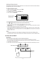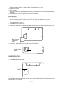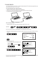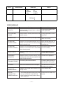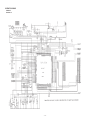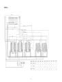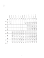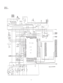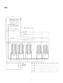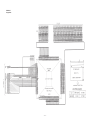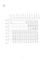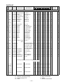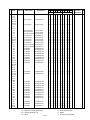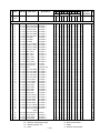
1
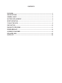
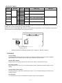
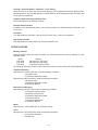
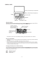
(without price)
CSF-4450/4650/4950(ZX-855✽E/✽F)
(Version ✽E and ✽F)
OCT. 1995
Caution: CSF-4✽50 includes 2 kinds of version-✽E and version-✽F. The functions are exactly the same
between two versions. As for details, refer to page-1.
INDEX
R
CONTENTS
FEATURES ..............................................................................................................................1
SPECIFICATIONS ...................................................................................................................2
GENERAL GUIDE ...................................................................................................................5
BATTERY REPLACEMENT ....................................................................................................6
RESET OPERATION ...............................................................................................................7
TO SAVE THE DATA .............................................................................................................. 9
PIN FUNCTION ...................................................................................................................... 10
DIAGNOSTIC PROGRAM ..................................................................................................... 11
ERROR MESSAGE ...............................................................................................................14
SCHEMATIC DIAGRAMS ..................................................................................................... 15
EXPLODED VIEW .................................................................................................................23
PARTS LIST ..........................................................................................................................24
VERSION TABLE
Version
Model
CSF-4450 Version✽E AE
CSF-4650
EE
FE
CSF-4950
IE
JE
CSF-4450 Version✽F AF
CSF-4650
EF
FF
CSF-4950
IF
JF
N o t e Capacity
PCB ass'y
TAB-LSI
Standard
32KB
Z855-1E ASS'Y (MC100012✽1) OC3015-F1 SUB ASS'Y
Standard
64KB
Z855-1E ASS'Y (MC100012✽2)
B.O.S.S.
Standard 128KB Z855-1E ASS'Y (MC100012✽3)
B.O.S.S.
Standard
32KB
Z855-1 ASS'Y (MC100011✽1)
COF3011-F1 SUB ASS'Y
Standard
64KB
Z855-1 ASS'Y (MC100011✽2)
B.O.S.S.
Standard 128KB Z855-1 ASS'Y (MC100011✽3)
B.O.S.S.
CSF-4✽50 includes 2 kinds of version-✽E and version-✽F as shown in the table above. Although the TAB-LSI is different
between two versions the functions are exactly the same.
A difference of two versions (✽E and ✽F) cannot be confirmed from the appearance, but it is recognized by production
number on back of the backup battery cover as shown below.
Backup Battery Cover
RESET
5M 111A
XX XXXE: Version-]E
XX XXXA: Version-]F
When the last letter of production number is E it is version-]E. When A, version-]F.
FEATURES
3-color display
The display shows data in three colors: orange, blue and green. Different colors can be used to highlight
specific dates in the Calendar, and even the color of text data can be specified.
Desktop Menu System
Simply point to the item that represent the function you want to use and press a button.
Do Today Function
Every time you turn on the unit, any Schedule Keeper items scheduled for that date appear on the
display.
Powerful data bank functions
Telephone Directory, Business Card Directory, Memo, To Do, Expense Manager, Reminder, and
Schedule Keeper.
Secret Drawer
A convenient place to lock up confidential information using a secret password.
—1—
Calendar - Schedule Keeper - Reminder - To Do linking
Reminder and To Do items are automatically displayed in the applicable Schedule Keeper dates.
Markers appear on the Calendar display to indicate dates for which Schedule Keeper, Reminder, and
To Do items are scheduled.
Timepiece with Home time and World Time
Dual timekeeping for two different locations.
Powerful alarm functions
In addition to the standard daily alarm, you can also set alarms for Schedule Keeper, Reminder, and
To Do items.
Calculator
A 12-digit arithmetic calculator is just the thing for those quick, on-the-go calculations.
Data Communication
Exchange data with another CSF Unit or with a CASIO SF Unit.
SPECIFICATIONS
Memory Capacity
Memory capacity differs according to model. The following shows the memory capacity for each
available model.
Model
Memory
CSF-4450
32K bytes (27,337 bytes)
CSF-4650
64K bytes (60,105 bytes)
CSF-4950
128K bytes (125,641 bytes)
The following shows the number or items that can be stored in each model (CSF-4450/4650/4950).
Telephone Directory
Approximately 1,200/2,700/5,700, under the following conditions:
8-character name
10-character telephone number
Approximately 600/1,300/2,900, under the following conditions:
8-character name
10-character telephone number
20-character address
Business Card Directory
Approximately 300/700/1,500, under the following conditions:
10-character employer name
8-character personal name
10-character telephone number
10-character position
10-character department
20-character address
Memo
Approximately 1,100/2,600/5,400, 20-character memos.
To Do
Approximately 700/1,600/3,400, under the following conditions:
20 character description
Deadline set
—2—
Schedule Keeper
Approximately 700/1,500/3,200, under the following conditions:
20 character description
Illustration used
Starting time specified, alarm time set
Approximately 900/2,000/4,100, under the following conditions:
20 character description
Illustration not used
Starting time specified, no alarm time
Reminder
Approximately 1,500/3,300/6,900, under the following conditions:
10 character description
Alarm time set
Approximately 1,700/3,700/7,800, under the following conditions:
10 character description
No alarm time
Expense Manager
Approximately 800/1,800/3,800, under the following conditions:
10 character description
Expense type and payment type set
Main Modes:
Telephone Directory, Business Card Directory, Memo, Schedule Keeper, To Do, Expense Manager,
Reminder, Calendar, Home Time, World Time and Calculator
Data storage:
Storage and recall of telephone, business card, memo, schedule, to do, expense, reminder data;
calendar display; secret drawer; editing; memory status display
Clock:
Worldtime; reminder alarm; schedule alarm; to do alarm; daily alarm; accuracy under normal temperatures: ±3 seconds average
Calculation:
12-digit arithmetic calculations; arithmetic constants (+, -, ×, ÷); independent memory; percentages;
square roots; 24-digit approximations; date calculations; other mixed calculations
General:
Display element:
16-column × 4-line LCD
Main component:
LSI
Power supply:
Main:
Back-up:
Two AAA-size batteries (Type: R03 (UM-4) or LR03 (AM4))
One CR2032 lithium battery
Current consumption:
ON:
OFF:
Backup Battery:
4 mA or under (TEL mode)
25 µA or under
10 µA or under
Low Battery message:
Main battery:
Backup battery:
2.5 V ± 2.5%
2.6 V ± 2.5%
Forced power off:
2.3 V ± 2.5%
—3—
Battery life:
Main:
Back-up:
Approximately 100 hours continuous display in Telephone Directory (approximately 180 hours on type LR03 (AM4)); approximately 80 hours repeating one
minute of input and 10 minutes of display in Telephone Directory (approximately
150 hours on type LR03 (AM4))
5 years if main batteries are replaced as soon as they become weak. 2 year if
dead main batteries are left in the unit.
Power consumption:
Auto power off:
0.06 W
Approximately 6 minutes after last key operation
Operating temperature:
Dimensions:
Unfolded:
Folded:
0°C ~ 40°C (32°F ~ 104°F)
10.5H × 145W × 176.5D mm (7/16"H × 511/16"W × 615/16"D)
14.2H × 145W × 95D mm (9/16"W × 511/16"W × 33/4"D)
Weight: 142.2 g (5 oz) including batteries
—4—
GENERAL GUIDE
OFF key - Press this key to turn power off.
ON key - Press this key to turn power on.
Display
Cursor Key Pad
Keyboard
MENU key
COLOR SELECT keys
About the desktop...
The desktop gives you point-and-select access to the data management features of the CSF Unit.
Whenever you want to return to the desktop, simply press the MENU button.
Calendar, Schedule
Keeper, Reminder and
Expense Manager
Home Time, World
Time, and Alarm
Calculator
Telephone Directory
and Business Card
Directory
Secret Drawer
To Do
Memo
• Note that one of the icons on the desktop is flashing, This means that the icon is selected.
How to use the desktop
1. Use the cursor keys to move the flashing around the desktop until the one you want is selected
(flashing).
2. After selecting an icon, press OK to access the functions of that icon.
• Selecting some icons (like the Clock and Telephone) cause another selection screen to appear.
• Details on actually using the features and functions that you access from the desktop are described
in the other sections of this manual.
Changing the Desktop Screen's Window Scenery
You can change the scenery that is outside the desktop screen's window to any one of the scenes
shown below. Simply display the desktop screen and press the COLOR SELECT key that corresponds
to the scenery you want to select.
ORG:
BLU:
GRN:
Night-time city scene
Daytime city scene
Beach scene
—5—
Adjusting the Display Contrast
The following procedure describes how to adjust the color contrast, which controls the relative darkness
and lightness of each color on the display.
To adjust the display contrast
1. While the desktop is on the display, press FUNC.
2. Press 1 to select SYSTEM .
3. Press
to display the second SYSTEM menu.
4. Press 1 to select CONTRAST.
<O
Pointer (currently
selected color)
B
G>
(ORG)
(BLU)
(GRN)
5.
6.
•
•
Use
and
to move the pointer to the color whose contrast you want to set.
Use
and
to adjust the contrast of the currently selected color.
You can adjust the overall contrast of the display by pressing or .
Whenever you press one of the COLOR SELECT keys, the color contrast is returned to its initial
default setting.
7. After you finish adjusting the display contrast, press OK.
• Color contrast settings are registered as soon as you make them. Because of this, pressing either
OK or ESC quits the color contrast procedure only. Pressing ESC does not return the color contrast
setting to what is was.
Notes
• Temperature changes can cause changes in background color and the tint of display colors .
• Low battery power can also cause flickering of the display and changes in the tint of display colors.
BATTERY REPLACEMENT
Main Battery
Before replacing the main batteries, note the following precautions:
• Do not remove the main batteries from the CSF Unit while back-up battery is removed.
• Be sure to replace both batteries at the same time, and do not use an old battery with a new one.
1. Press OFF to switch power OFF.
2. Press down at the two locations indicated by , and slide in the direction indicated by the arrow.
∇
Main battery holder
AAA-size
batteries
RESET
—6—
3.
•
4.
5.
•
Remove both old batteries and replace them with two new ones.
Make sure that the positive (+) and negative (-) ends are facing correctly.
Replace the holder.
Turn on power.
The Home Time screen always appears whenever you turn power on for the first time after replacing
batteries.
6. Check the Home Time setting and make changes if necessary.
Back-up Battery
Before replacing the back-up battery, note the following precautions:
• Do not remove the back-up battery from the CSF Unit while main batteries are removed.
• Be sure to replace the back-up battery at least once every five years. Otherwise, you run the risk of
losing data stored in memory.
1. Press OFF to switch power OFF.
2. Remove the screws that hold the back-up battery compartment cover in place, and remove the cover.
RESET
Back-up battery
compartment
cover
3. Insert a thin, pointed object into (A) and remove the old battery.
CR2032 lithium
battery
(A)
RESET OPERATION
1. Press ON to switch power ON.
2. Press the RESET button with a thin, pointed object.
RESET
button
RESET
Warning!
The next step deletes all data stored in the CSF Unit's memory. Make sure that you really want to delete
the data before you continue!
—7—
3. Press 1 to select ALL RESET.
Note
• The above message always appears in English, regardless of the system language setting.
4. Press OK to reset the memory and delete all data or ESC to abort the reset operation without deleting
anything.
• After the ALL RESET operation is complete, the LANGUAGE screen appears on the display.
5. Check the Home Time setting and make changes if necessary.
Following the all reset operation, the CSF Unit settings are initialized as noted below.
Home Time:
World Time:
Daily Alarm:
Sound:
Messages:
Character input:
LON
1996/1/1 MON
12:00 AM
12-hour format
NYC
12:00 PM
Data alarm (Schedule alarm, Reminder alarm and To Do alarm) — ON
Daily alarm — OFF
Key — ON
English
CAPS
To perform SECRET RESET
Important!
• The following procedure erases all data stored in the secret drawer. Make sure you do not need any
of the data in the secret drawer before deleting it. You can transfer data you might need to the desktop
(page 9) before performing this procedure.
• Note that this unit has no procedure for deleting the password only (and leaving secret drawer
contents) or secret drawer contents only (and leaving the password).
To perform a SECRET RESET, follow the same procedure as that described under "RESET
OPERATION" on page 7, except you should select "SECRET RESET " in step 3.
—8—
TO SAVE THE DATA
CSF-4450/4650/4950 can transfer the customer's data to another CSF unit with memory protection only
when replacing the LCD or the outer case.
To connect the CSF Unit to another CSF Unit
1. Make sure that the power of both units are switched off.
2. Remove the covers from the data communications jacks on the two CSF Units.
3. Connect the two units using the SB-62 cable.
How to transfer the data
1. Under calculator mode, set the date of the slave unit to Feb. 3rd, 1901.
Operation :
ON
OK
1
DATE
2
DATE
3
DATE
M+
If you do not set the date, the "PASSWORD" is not transferred to the slave unit.
2. Check the hardware parameters of both unit, and if both units have another condition, reset as
follows;
MENU
FUNC
2
3
//////////// SET UP PAR. ////////////
PARITY
BIT LENGTH
BPS
E/O/N
N
7/8
4800 / 9600
OK
3. Set up the slave unit.
• On the desktop, select the telephone icon
RECEIVE OK!
and press OK .
DATA
• Select the home icon and press OK .
•
FUNC
2
TO STOP
PRESS [ ESC ]
2
4. Set up the customer's unit.
MENU
FUNC
2
1
3
OK
SENDING!
DATA
TO STOP
PRESS [ ESC ]
If you can not succeed to transfer the data, press ESC key on both units and try to transfer the data again
following the procedure above.
—9—
PIN FUNCTION
CPU HCD62121A02 (HC-3017) : COB
NOTE: The CPU is bonding on the PCB. If the CPU is defective, replace the Z855-1 PCB ass'y
because the CPU cannot be replaced.
Pin No.
Pin Name
Input/Output
1 ~ 14
15 ~ 22
23
24
25
26 ~ 46
47 ~ 54
55
56
57 ~ 64
65
69 ~ 72
73
74
75
76
80
81
82
83
84
85
86
87
88
89, 90
91
92
93
94
95
96
97
98
99
100
101
102
103
104
105
KO14 ~ KO1
KI8 ~ KI1
BUFON
IT2
IT0
AO20 ~ AO0
IO0 ~ IO7
OEBO
WEBO
CS10BO ~ CS3BO
OPT7
OPT3 ~ OPT0
PORT7
PORT6
PORT5
PORT4
PORT0
VSS
PI
PO
VDD
XO
XI
VCC
VREG2
TS1, TS2
VSSR
BZZ1
BZZ2
VSS
OCLK
ITOFF
TEMU
SW
VDB
VREG1
VREG4
VREG5
VDT1I
VDT2I
VREG3
O
I
O
I
I
O
I/O
O
O
O
O
O
I
I
O
O
I
I
I
O
I
O
I
I
O
—
I
O
O
I
O
I
—
I
I
—
O
—
I
I
—
Function
Key common signal
Key input signal
Chip select for RAM
Interrupt input
Interrupt input
Address bus
Data bus
Output enable signal for RAM
Write enable signal for RAM
Chip selecting signals
Reset signal output
Changeover signal
Receiving terminal for data communication
Receiving terminal for data communication
Transmitting terminal for data communication
Transmitting terminal for data communication
Low battery message for back-up battery (2.6V)
GND
1MHz clock input
1MHz clock output
+3V source
4.3MHz clock output
4.3MHz clock input
+3V source
Voltage for main switch detection
Test terminals of factory purpose only
GND
Buzzer signal output
Buzzer signal output
GND
Clock output
Switching terminal from main switch
Test terminals of factory purpose only
Receiving terminal for reset switch
+3V source
Test terminals of factory purpose only
+3V source for ROM
Test terminals of factory purpose only
Forced power off detecting terminal (2.3V)
Low battery message for main battery (2.5V)
+3V source for RAM
— 10 —
DIAGNOSTIC PROGRAM
Test pad
Main switch
RESET
Bottom View
To enter the diagnostic program, proceed as follows;
1 : Open the battery cover and slide the main switch to the arrow side.
2 : Press ON while shorting the Test pad.
STEP
Enter the
diagnostics
OPERATION
Press ON while shorting
the Test pad.
DISPLAY
///// SELF TEST PROG /////
PRESS OK KEY
QUIT BY OFF KEY
1
CASIO OCT 1995
TEST
4 BUZZER
1 DISP
5 I/F
2 MEMORY
6 CONT
3 KEY
7 RESET
DISPLAY
1 DISPLAY
2 FRAME FREQ.
No color, no display
OK
Orange color is displayed
OK
Green color is displayed
OK
Blue color is displayed
OK
Checkers are displayed
OK
Reverse checkers are displayed
OK
Frame is displayed
OK
OK
Dots at the 4 corners are
displayed
Vertical 4 colors are displayed
OK
Horizontal 4 colors are displayed
OK
TEST
1 DISP
2 MEMORY
3 KEY
Main menu
OK
Display
Check
1
4
5
6
7
— 11 —
BUZZER
I/F
CONT
RESET
NOTE
STEP
Memory
Check
OPERATION
2
DISPLAY
MEMORY
1 WR 1
2 READ 1
1
1 WR 1
2 READ 1
Memory
Check
OK
3
RAM WRITE 2
OK
6
OK
ESC
3
4
5
6
WR 2
READ 2
DUMP
CHKSUM
EXECUTING !!
CMPLETE !!
32/64/128 KB
MEMORY
3 WR 2
4 READ 2
1 WR 1
5 DUMP
2 READ 1
6 CHKSUM
5
Memory
Check
WR 2
READ 2
DUMP
CHKSUM
CMPLETE !!
32/64/128 KB
MEMORY
3 WR 2
4 READ 2
1 WR 1
5 DUMP
2 READ 1
6 CHKSUM
1 WR 1
2 READ 1
OK
3
4
5
6
EXECUTING !!
MEMORY
4
WR 2
READ 2
DUMP
CHKSUM
RAM WRITE 1
MEMORY
2
3
4
5
6
XXXX
MEMORY
3
4
5
6
1 WR 1
2 READ 1
CHECK SUM
TY SZ SUM
C5 0 512 XXX
MEMORY
3
4
1 WR 1
5
2 READ 1
6
TEST
4
1 DISP
5
2 MEMORY
6
3 KEY
7
— 12 —
NOTE
Write the test pattern 1 into RAM
After 1 sec.
Read the test pattern 1 from RAM
After 1 sec.
Write the test pattern 2 into RAM
After 1 sec.
Read the test pattern 2 from RAM
After 1 sec.
Wiring check for ROM
WR 2
READ 2
DUMP
CHKSUM
XOR
XX
WR 2
READ 2
DUMP
CHKSUM
BUZZER
I/F
CONT
RESET
Check SUM value
Version- ✽E = 65D6
Version- ✽F = E146
STEP
OPERATION
KEY CHECK 3
DISPLAY
KEY & TIME
1 RANDOM
2 AUTO
3 TIME
1
Buzzer
Check
16 17 18 19
OK
TEST
1 DISP
2 MEMORY
3 KEY
BUZZER
ESC
Interface
Check
No display
ESC, 1, 2, 3.......
4
5
TEST
1 DISP
2 MEMORY
3 KEY
I/F
7N9
1
2
Contrast up :
or SHIFT +
Contrast down :
or SHIFT +
Cursor keys
4
5
6
7
1
2
3
4
5
6
7
1
2
3
4
BUZZER
I/F
CONT
RESET
BEEP
ALARM 1
ALARM 2
BUZZER
I/F
CONT
RESET
TRANS
RECEIVE
ASCII
LOOP
No display
EXECUTING !!
4
CONTRAST 6
ADJ.
.....
EXECUTING !!
3
ESC
NOTE
EXECUTING !!
To push the key sequentially that
key code is being appeared in
the display.
1 : Key input sound
2 : Sound alarm 1
3 : Sound alarm 2
The parameter can be changed
as follows;
Key "5" : Bit length 7 or 8 bit
Key "6" : Parity bit N(Non),
E(Even) or O(Odd)
Key "7" : BPS 9(9600) or 4(4800)
Send the code "H"
Display the received charactor.
Send the ASCII code
Loop back check
I/F
1 TRANS
2 RECEIVE
7N9
3 ASCII
4 LOOP
TEST
4 BUZZER
1 DISP
5 I/F
2 MEMORY
6 CONT
3 KEY
7 RESET
//////////// CONTRAST ////////////
<O
B
G>
(ORG)
(BLU)
(GRN)
//////////// CONTRAST ////////////
<O
B
G>
(ORG)
(BLU)
(GRN)
— 13 —
Contrast adjustment
Adjust the color using cursor keys
until the primary colors appear
accurately.
STEP
OPERATION
OK
RESET
7
DISPLAY
TEST
1 DISP
2 MEMORY
3 KEY
NAME?
4
5
6
7
NOTE
BUZZER
I/F
CONT
RESET
END
TELEPHONE
0
ERROR MESSAGE
Meaning
Action
NO DATA!
Search operation attempted when no data is
stored in memory.
Current search operation cannot be performed.
DATA ITEM NOT
FOUND!
Data specified in search operation does not
exist in memory.
Change specification or cancel search.
MEMORY FULL!
No more room in memory for storage of data.
Delete unnecessary data
items from memory.
ALARM TIME
ALREADY USED!
Attempt to set a Schedule Keeper, a Reminder or a To Do alarm time that is already
used for another entry.
Set a different alarm time or
change the existing alarm time
to another one.
ALARM TIME
ALREADY PASSED!
Attempt to set a Schedule Keeper, a Reminder or a To Do alarm time for a time/date
that is already passed.
Set a different alarm time (for
a future time/date).
SECRET DATA!
Alarm for a secret memory area data item is
sounding.
Enter the secret memory area
to view details of the alarm.
PASSWORD
MISMATCH!
Attempt to enter the secret memory area
using a password that does not match the one
preset for the secret area.
Use the correct password.
TRANSMIT ERROR!
Error during data communications.
Cancel the data communications operation and try again.
STOPPED!
Data communication has been interrupted.
Stop the data communication
procedure and try again.
SAME TYPE
ALREADY USED!
Attempt to store a label that is identical to one
already stored.
Use a different label.
NOTICE!
CONSULT THE
OWNER'S MANUAL!
• This message appears when this is the first
time you ever turned on the CSF Unit.
• Data corrupted by strong impact, electrostatic charge, etc.
Perform the ALL RESET operation.
Message
— 14 —
SCHEMATIC DIAGRAMS
VERSION*E
Main Block-1/2
— 15 —
VERSION*E
Main Block-2/2
— 16 —
VERSION*E
Display Block
— 17 —
VERSION*E
Key Matrix
— 18 —
VERSION*F
Main Block-1/2
— 19 —
VERSION*F
Main Block-2/2
— 20 —
VERSION*F
Display Block
— 21 —
VERSION*F
Key Matrix
— 22 —
EXPLODED VIEW
1
17
2
18
3
4
19
5
6
Version-✽F
20
28
29
30
7
7
8
21
10
11
9
11
12
12
22
31
23
13
31
14
24
25
15
13
26
27
16
— 23 —
Version-✽E
PARTS LIST
Quantity
Code No.
Parts Name
Specification
AE AF EE FE EF FF IE IF JE JF M
4650
4950
4450
FOB Japan
N.R.Yen
R
Unit Price
N
Item
N
N
7
10
12
21
22
29
D30
D4
D4,
D100
D5
D6
IC1
IC10
IC11
IC12
IC30
IC4
IC6
IC7
IC8
IC9
L1
LSI2
3335 6055
6417 2620
3501 6405
5610 9160
6417 2610
6417 4840
2390 1561
2390 0875
2390 0875
LCD
Battery Spring M-B
Mini Jack
Heat Seal Z855
Battery Spring P-B
LCD ASS'Y
Schottky Diode
Chip Diode
Chip Diode
CD1034-TS
C413028-1
HSJ1169-012010
MC300555-1
C311911-1
MC300003*1
MA724-(TX)
MA704-(TX)
MA704-(TX)
0
1
1
0
1
1
1
0
2
1
1
1
1
1
0
1
1
0
0
1
1
0
1
1
1
0
2
0
1
1
0
1
1
1
0
2
1
1
1
1
1
0
1
1
0
1
1
1
1
1
0
1
1
0
0
1
1
0
1
1
1
0
2
1
1
1
1
1
0
1
1
0
0
1
1
0
1
1
1
0
2
1
1
1
1
1
0
1
1
0
1
20
5
5
20
1
10
20
20
B
X
C
B
X
B
C
C
C
2390 0364
2390 1442
2114 4795
2105 5236
2105 4704
2105 1561
2105 5096
2105 2737
2105 4228
2105 4914
2105 4144
2105 5222
3841 1799
6413 5320
MA713-TX
MA152K-(TX)
TC74HC4066AF(EL)
TC74HC32AF(EL)
RH5RE25AA-T1
TC7S04F-TE85R
XC6382A501PR
RH5RL50AA-T1
RH5VL25CA-T1
RH5VL23CA-T1
RH5VL26CA-T1
TC74HC04AF(EL)
636CY-151M-P3
A340214*1
1
0
1
0
0
0
1
1
1
1
1
1
1
0
1
1
1
0
1
0
1
1
1
1
1
1
1
1
1
0
1
1
0
1
1
1
1
1
1
1
1
0
1
0
1
1
0
1
1
1
1
1
1
1
1
0
1
1
1
1
1
1
1
1
1
1
1
1
1
1
1
1
1
1
1
1
1
1
1
1
1
1
1
1
1
0
1
0
0
0
1
1
1
1
1
1
1
0
1
1
1
0
1
0
1
1
1
1
1
1
1
1
1
0
1
0
0
0
1
1
1
1
1
1
1
0
1
1
1
0
1
0
1
1
1
1
1
1
1
1
10
20
5
10
5
10
1
10
10
10
10
10
5
1
C
C
B
B
B
B
B
B
B
B
B
B
C
B
LSI3
LSI3
LSI4
LSI6
LSI6~7
Q100
Q5
Q6
THR1
VR1
X1
X2
2012 2394
2012 3493
2012 1659
2012 3192
2012 3192
2250 1281
2254 0287
2259 0959
2755 0147
2765 1869
2590 1967
7110 0642
Schottky Diode
Chip Diode
CMOS IC
CMOS IC
CMOS IC
CMOS IC
CMOS IC
CMOS IC
MOS IC
MOS IC
MOS IC
CMOS IC
Coil
COF3011-F1 SUB
ASS'Y
LSI
LSI
LSI
LSI
LSI
Chip Transistor
Transistor(FET)
Chip Transistor
Thermistor
Chip Volume
Ceramic Oscillator
Crystal Oscillator
UPD23C4001EJGW-C17
UPD23C4001EJGW-C31
TC551001BFL-10V(S)
TC55257DFL-7085V
TC55257DFL-7085V
2SA1179M5,M6,M7-TB
2SK1133-T1B
DTC114YKT-146
104HT
MVR32HXBRN503
CSTC4.30MG-TC
DT-26S
0
1
0
1
0
1
1
1
1
1
1
1
1
0
0
1
0
0
1
1
1
1
1
1
0
1
0
0
2
1
1
1
1
1
1
1
0
1
0
0
2
1
1
1
1
1
1
1
1
0
0
0
2
0
1
1
1
1
1
1
1
0
0
0
2
0
1
1
1
1
1
1
0
1
1
0
0
1
1
1
1
1
1
1
1
0
1
0
0
0
1
1
1
1
1
1
0
1
1
0
0
1
1
1
1
1
1
1
1
0
1
0
0
0
1
1
1
1
1
1
1
1
1
1
20
10
20
5
20
5
5
B
B
B
B
B
C
C
C
C
C
C
C
PCB ASS'Y(Z855-1 ASS'Y & Z855-1E ASS'Y)
N
N
N
N
N
N
N
N
N
N
N
N
The following electronic parts will be not supplied from CASIO.
C1~4,C9,
C19~20,
C51~53
C1~4,
C9,C20,
C51~55
C5,C35,
C39,C66,
CB5~7
Notes:
N
M
Q
R
Chip Condensor
MCH312F105ZP
Chip Condensor
MCH312F105ZP
11
Chip Condensor
MCH183F104ZK
0
–
–
–
–
New parts
Minimum order/supply quantity
Quantity used per unit
Rank
— 24 —
0 10
0
0 10 10
0 10
0 10
0 11 11
0
0 11
0 11
0
0
7
7
0
0
0
0
R–A:
B:
C:
X:
0
0
Essential
Stock recommended
Others
No stock recommended
Quantity
N
Item
Code No.
C5,C35,
C39,
CB4~7
C5,C35,
C39,C66,
CB5~6
C5,C35,
C39,
CB4~6
C7
C18
C19
C37
C41,C42
C54,C55
C56~61
C56~57
C34
C33
R1
R16
R17
R18
R19
R20
R20
R21,R32
R21,R32,
R42,R100,
R106,
R111,
R208
R21,R74
R21,R74,
R42,R100,
R106,
R111,
R208
R22
R22
R23
R25
R26
R27
R28
R31
R33
R36,
R71~73
R50
R56
R102,
R103
Notes:
Parts Name
Specification
Chip Condensor
MCH183F104ZK
0
0
7
7
0
0
0
0
0
0
Chip Condensor
MCH183F104ZK
0
6
0
0
0
0
0
6
0
6
Chip Condensor
MCH183F104ZK
6
0
0
0
0
0
6
0
6
0
ECST1AY106R
ECSTOJY106R
Tantalum Condensor ECST1DY335R
Chip Condensor
MCH185A221JK
Chip Condensor
MCH185A160JK
Chip Condensor
MCH213F105ZP
Chip Condensor
MCH212C154KP
Chip Condensor
MCH212C154KP
Electrolytic Capacitor ECEA1AKS1011
Electrolytic Capacitor ECEA0JKA1011
Chip Resistor
MCR03EZHJ153
Chip Resistor
MCR03EZHG202
Chip Resistor
MCR03EZHG102
Chip Resistor
MCR03EZHG822
Chip Resistor
MCR03EZHG392
Chip Resistor
MCR03EZHF1053
Chip Resistor
MCR03EZHF4532
Chip Resistor
MCR03EZHJ000
Chip Resistor
MCR03EZHJ000
1
0
1
1
2
0
0
2
1
1
1
1
1
1
1
0
1
0
7
1
1
0
1
2
2
6
0
1
1
1
1
1
1
1
1
0
2
0
1
0
1
1
2
0
0
2
1
1
1
1
1
1
1
0
1
0
0
1
0
1
1
2
0
0
2
1
1
1
1
1
1
1
0
1
0
0
1
1
0
1
2
2
6
0
1
1
1
1
1
1
1
1
0
0
0
1
1
0
1
2
2
6
0
1
1
1
1
1
1
1
1
0
0
0
1
0
1
1
2
0
0
2
1
1
1
1
1
1
1
0
1
0
7
1
1
0
1
2
2
6
0
1
1
1
1
1
1
1
1
0
2
0
1
0
1
1
2
0
0
2
1
1
1
1
1
1
1
0
1
0
7
1
1
0
1
2
2
6
0
1
1
1
1
1
1
1
1
0
2
0
Chip Resistor
Chip Resistor
MCR03EZHJ000
MCR03EZHJ000
0
0
0
0
0
7
0
7
2
0
2
0
0
0
0
0
0
0
0
0
Chip Resistor
Chip Resistor
Chip Resistor
Chip Resistor
Chip Resistor
Chip Resistor
Chip Resistor
Chip Resistor
Chip Resistor
Chip Resistor
MCR03EZHF5622
MCR03EZHF5362
MCR03EZHF1003
MCR03EZHJ182
MCR03EZHJ473
MCR03EZHJ102
MCR03EZHG105
MCR03EZHJ475
MCR03EZHJ105
MCR03EZHJ823
0
1
1
1
1
1
1
1
1
4
1
0
1
1
1
1
1
1
1
4
0
1
1
1
1
1
1
1
1
4
0
1
1
1
1
1
1
1
1
4
1
0
1
1
1
1
1
1
1
4
1
0
1
1
1
1
1
1
1
4
0
1
1
1
1
1
1
1
1
4
1
0
1
1
1
1
1
1
1
4
0
1
1
1
1
1
1
1
1
4
1
0
1
1
1
1
1
1
1
4
Chip Resistor
Chip Resistor
Chip Resistor
MCR03EZHJ184
MCR03EZHJ106
MCR03EZHJ474
1
1
2
1
1
0
1
1
2
1
1
2
1
1
0
1
1
0
1
1
2
1
1
0
1
1
2
1
1
0
C/CAP (Tantalum)
C/CAP (Tantalum)
N
M
Q
R
AE AF EE FE EF FF IE IF JE JF M
4650
4950
4450
–
–
–
–
New parts
Minimum order/supply quantity
Quantity used per unit
Rank
— 25 —
R–A:
B:
C:
X:
Essential
Stock recommended
Others
No stock recommended
FOB Japan
N.R.Yen
R
Unit Price
Quantity
N
Item
Code No.
R115,
R116
Parts Name
Chip Resistor
Specification
MCR03EZHJ301
AE AF EE FE EF FF IE IF JE JF M
4650
4950
4450
FOB Japan
N.R.Yen
R
Unit Price
2
0
2
2
0
0
2
0
2
0
1
0
1
1
0
0
1
0
0
1
1
0
0
0
0
0
1
0
0
1
1
1
1
0
0
0
0
1
0
0
1
0
0
0
0
1
0
0
0
0
1
1
1
1
0
1
1
0
0
1
0
0
1
1
0
0
1
0
0
0
0
0
1
1
1
1
0
0
0
0
1
0
0
1
0
0
0
0
1
0
0
0
0
1
1
1
1
0
1
0
1
0
0
1
0
1
0
1
0
0
0
0
0
1
0
1
1
1
0
1
0
0
0
0
1
0
0
1
0
0
0
0
1
0
0
0
1
1
1
1
0
1
0
1
0
0
1
0
1
0
1
0
0
0
0
0
1
0
1
1
1
0
0
1
0
0
0
1
0
0
0
1
0
0
0
0
1
0
0
1
1
1
1
0
1
0
1
0
0
1
0
1
0
1
0
0
1
0
0
0
0
1
1
1
0
1
0
0
0
0
1
0
0
1
0
0
0
0
1
0
0
0
1
1
1
1
0
1
0
1
0
0
1
0
1
0
1
0
0
1
0
0
0
0
1
1
1
0
0
1
0
0
0
1
0
0
0
1
0
0
0
0
1
0
0
1
1
1
0 0
1 1
1 1
0 0
0 0
1 1
0 0
0 0
1 1
1 1
0 0
0 0
1 1
0 0
0 0
0 1
0 0
0 0
1 0
1 1
1 11
1 1
0 0
0 0
0 0
1 1
0 0
0 0
0 0
1 1
0 0
0 0
0 0
1 1
0 0
0 0
0 0
0 0
1 1
0 0
1 1
1 1
1 1
0
1
1
0
0
1
0
0
1
1
0
0
1
0
0
0
0
0
1
1
1
1
0
0
0
0
1
0
0
1
0
0
0
0
1
0
0
0
0
1
1
1
1
0
1
1
0
0
1
0
0
1
1
0
0
1
0
0
1
0
0
0
1
1
1
0
0
0
0
1
0
0
1
0
0
0
0
1
0
0
0
0
1
1
1
1
10
10
10
5
5
20
20
20
20
1
1
1
1
1
1
1
1
1
20
20
10
5
5
5
5
5
20
20
20
10
10
10
10
10
5
5
5
5
5
20
20
20
C
C
B
X
X
X
B
B
B
B
C
C
C
B
B
B
B
B
B
B
C
C
X
X
X
X
X
C
C
C
X
X
X
X
X
X
X
X
X
X
B
B
X
1
1
0
0
1
1
0
0
1
0
1
0
1
0
1
0
1
0
1
0
1
0
1
0
1
0
0
1
1
0
0
1
1
0
0
1
20
20
20
20
B
B
B
B
COMPONENT
N
N
N
N
N
N
N
N
N
N
N
N
N
N
N
N
N
N
N
N
N
N
N
N
N
N
N
N
N
N
N
N
N
N
N
N
N
N
N
N
1
1
2
3
3
3
4
4
4
5
6
6
6
8
8
8
9
9
9
11
13
14
15
15
15
15
15
16
16
16
17
17
17
17
17
18
18
18
18
18
19
20
23
6417 2270
6417 2510
6417 2570
6417 2150
6417 2320
6417 2430
6417 2200
6417 2370
6417 2480
6417 2230
6417 2250
6417 2380
6417 2490
6417 3290
6417 3300
6417 3310
6417 3320
6417 3330
6417 3340
6390 0430
6408 9400
3122 2380
6417 2160
6417 2330
6417 2400
6417 2440
6417 2520
6417 2190
6417 2360
6417 2470
6417 2300
6417 2390
6417 2420
6417 2500
6417 2540
6417 2170
6417 2340
6417 2410
6417 2450
6417 2530
6417 2220
6417 2240
6417 2260
N
N
N
24
25
25
25
6324 1962
6417 2210
6417 2590
6417 2600
Notes:
N
M
Q
R
Display Plate Z855A
Display Plate Z855I
LCD Spacer Z855
Upper Case Z855A
Upper Case Z855E
Upper Case Z855I
Knob Z855A
Knob Z855E
Knob Z855I
Key Top CB-Z855A
Rubber Key Z855A
Rubber Key Z855E
Rubber Key Z855I
Z855-1 ASS'Y
Z855-1 ASS'Y
Z855-1 ASS'Y
Z855-1E ASS'Y
Z855-1E ASS'Y
Z855-1E ASS'Y
Jack Cover V322
Battery Spring A
MC300518-1
MC300518-2
MC400054-1
MC100005-1
MC100005-2
MC100005-3
MC200009-1
MC200009-2
MC200009-3
MC300523-2
MC100009-1
MC100009-2
MC100009-3
MC100011*1
MC100011*2
MC100011*3
MC100012*1
MC100012*2
MC100012*3
A310765-1
C413028-2
Buzzer
EFB-S55C41A8
Lower Case Z855A MC100006-1
Lower Case Z855E MC100006-2
Lower Case Z855F MC100006-3
Lower Case Z855I
MC100006-4
Lower Case Z855J MC100006-5
B Cover B Z855A
MC300501-1
B Cover B Z855E
MC300501-2
B Cover B Z855I
MC300501-3
Label H-Z855A
MC400052-1
Label H-Z855E
MC400052-2
Label H-Z855F
MC400052-3
Label H-Z855I
MC400052-4
Label H-Z855J
MC400052-5
Hard Case Z855A
MC100007-1
Hard Case Z855E
MC100007-2
Hard Case Z855F
MC100007-3
Hard Case Z855I
MC100007-4
Hard Case Z855J
MC100007-5
Key Top CR-Z855A MC300523-1
Key Top CG-Z855A MC300523-3
Buttery Spring PM-M MC400045-1
Z855A
Switch Spring G118 A43333-1
B Switch Z855A
MC200010-1
B Switch Z855E
MC200010-2
B Switch Z855I
MC200010-3
–
–
–
–
New parts
Minimum order/supply quantity
Quantity used per unit
Rank
— 26 —
R–A:
B:
C:
X:
1
0
0
1
Essential
Stock recommended
Others
No stock recommended
Quantity
N
Item
Code No.
Parts Name
N
N
N
N
26
27
27
27
28
31
6511 4881
6417 2180
6417 2350
6417 2460
6416 5860
6408 9410
Reset Button
B Cover A Z855A
B Cover A Z855E
B Cover A Z855I
Badge Label Z850
Battery Spring B
Specification
AE AF EE FE EF FF IE IF JE JF M
4650
4950
4450
FOB Japan
N.R.Yen
R
Unit Price
A311024-2
MC300500-1
MC300500-2
MC300500-3
C440972-1
C311911-2
1
1
0
0
1
1
1
1
0
0
1
1
1
0
1
0
1
1
1
0
1
0
1
1
1
0
1
0
1
1
1
0
1
0
1
1
1
0
0
1
1
1
1
0
0
1
1
1
1
0
0
1
1
1
1
0
0
1
1
1
20
20
20
20
20
20
B
C
C
C
X
C
C340532*3
1
0
1
1
0
0
1
0
1
0
1
B
CD1034-TS
MC300502-1
1
1
0
0
1
1
1
1
0
0
0
0
1
1
0
0
1
1
0
0
1
1
B
B
LCD ASS'Y
N
LSI10
N
N
7
30
6417 3871 OC3015-F1 SUB
ASS'Y
3335 6055 LCD
5610 9170 Heat Seal Z855
Notes:
N
M
Q
R
–
–
–
–
New parts
Minimum order/supply quantity
Quantity used per unit
Rank
— 27 —
R–A:
B:
C:
X:
Essential
Stock recommended
Others
No stock recommended
8-11-10, Nishi-Shinjuku
Shinjuku-ku, Tokyo 160, Japan
Telephone: 03-3347-4926