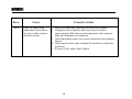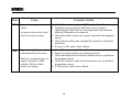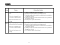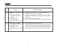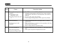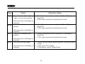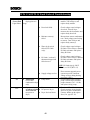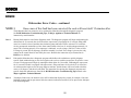
1
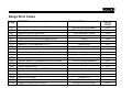
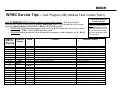
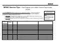
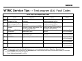
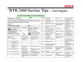
WFR 2460 Service Tips -- Test Program
The last 8 fault codes are stored & displayed!
HINT: # of errors
reads “0” for faults
which didn’t occur.
Look at # of errors,
not error #, to see
if faults occurred.
HINT: Scroll thru all errors
to check if any occurred.
B
Range Error Codes
CODE
DESCRIPTION
Oven temperature sensor failure
WHEN CHECKED
Cook or clean programmed
When W. Drawer is active
Latch should be locked
Latch should be unlocked
Always
Latch unlocked
Latch locked
Always
FAULT
LIMIT
20 sec
20 sec
1 min
1 min
1 min
5 sec
5sec
1 min
Always
1 min
Always
Cook or clean programmed
Always
1 min
1 sec
1 sec
1 sec
1 sec
F31
F33
F41
F43
F45
F111
F113
F121
Warning Drawer Sensor Failure
Motorized latch will not lock
Motorized latch will not unlock
Motorized Latch both locked and unlocked
Runaway Oven temperature 585°F
Runaway Oven temperature 950°F
Stuck key in the membrane switch layer
F125
Cancel key circuit problem
F141
F151
F153
F154
F155
Slave micro not functioning
Eeprom failure or communication circuit failure
User Interface too hot
Power Board too hot
Cook profile corrupted in EEPROM
Cook or clean Programmed
F170
F190
F200
F210
Power Failure
Power over voltage
Time out and stop function
Range exceeded safe test limits
Always
At power on
During Production test mode
During Service test mode
Always
2 ms
110 sec.
200°F
B
Range Error Codes – Additional Information
CODE
F1
F2
F3
DOOR
LATCH
ERROR
ERROR
DESCRIPTION
WHEN CHECKED
Meat probe not there or incorrect
During Test / use
Oven sensor not correct
During Test / use
Warming sensor not correct
During Test / use
Door latch problem
During self-clean
Temp. reaches 585 degrees F. Display shows “CONTACT During any cooking mode
SERVICE” and beeps. The beep can be stopped with
touching cancel zone, but display will stay up with
program locked until main power is removed for a
minimum of 5 seconds. If the temperature continues to rise
(due to stuck relay) the latch will lock at 600 degrees F
Note: Depending on model, program will only look for probes or sensors that it should have.
B
WFMC Service Tips – Test Program (2B): Module Fault Codes (Test1)
Last 8 fault codes are
stored & display!
Test P1:ERRORS / P:01 (Viewing control module fault codes) – Start & end test P1
(WFMC6400) / (P:01) (WFMC3200) by pushing Start/Pause button. Scroll through list of fault codes
by pushing Spin Selection (WFMC3200) or Menu (WFMC6400) buttons.
• WFMC3200 display alternates between fault code (e.g. E:01) & when fault occurred on in last 8
washes (e.g. : C:00) – shows C:00 if fault didn’t occur.
• WFMC6400 display shows fault code & when fault occurred on in last 8 washes (e.g. 0 – Er:01)
WFMC32
Display
WFMC64
Display
Test #
E:01
E:02
E:03
E:04
E:05
E:06
E:07
E:08
E:09
Er:01
Er:02
Er:03
Er:04
Er:05
Er:06
Er:07
Er:08
Er:09
washing
washing
washing
washing
P:16
------E:12
E:13
E:14
------E:20
E:21
E:22
E:24
Er:10
Er:11
Er:12
Er:13
Er:14
Er:15
Er:16
Er:20
Er:21
Er:22
Er:24
P:16
P:16
P:16
P:4
P:11
P:8/9/13
P:8/9/13
P:15
P:9
P:8
P:8
P:4
washing
P:4
Problem
Door open
Door lock doesn’t unlock
Door lock doesn’t lock
Door control broken
NTC open-circuited
NTC shorted
Unpexpected heating (heater on at wrong time)
Heater doesn’t shut off
Communication lost to motor
Flow meter gives wrong values
No water flow (within 6 minutes)
Water supply time exceeded
Drian pump time exceeded
Overflow level exceeded
Pressure sensor gives failure voltage level
Can’t calibrate pressure sensor
Spinning aborted due to unbalanced load
Excessive foam
Frequency synchronization failed
Motor power relay failed
HINT: # of faults reads “0”
for faults which didn’t occur.
Look at # of faults, not error
#, to see if faults occurred –
scroll thru all faults to check
if any occurred.
Possible Cause(s)
Door lock not engaged
Jammed lock or bad wire harness
Jammed lock or bad wire harness
Faulty Triac or control module
Faulty NTC or bad wire harness
Faulty NTC or bad wire harness
Faulty heater or stuck heater relay
Faulty heater or stuck heater relay
Faulty wire harness
Faulty flow meter or wire harness
Faulty inlet valve, wire harness, hose
Faulty inlet valve, wire harness, hose
Faulty drain pump, wire harness, hose
Faulty/blocked pump, hose, inlet valve
Faulty pressure sensor, wire harness
Faulty pressure sensor, wire harness
Unbalanced load or faulty wire harness
Wrong or too much detergent used
Faulty control module
Faulty control module
B
WFMC Service Tips – Test Program (2C): Motor Control Fault Codes
(Test1)
Last 16 fault codes are
stored & display!
Test P1:ERRORS / P:01 (Viewing motor control fault codes) – Start & end test P1 by
pushing Start/Pause button. Scroll through list of (18) fault codes by pushing Spin Selection
(WFMC3200) or Menu (WFMC6400) buttons.
• WFMC3200 display alternates between fault code (e.g. d:01) & when fault occurred on in last
16 washes (e.g. : C:00) – shows C:00 if fault didn’t occur.
• WFMC6400 display shows fault code & when fault occurred on in last 16 washes (e.g. 0 – Er:01)
WFMC32
Display
WFMC64
Display
d:01
d:02
d:03
d:06
d:07
d:08
d:09
d:10
d:11
d:12
d:13
d:14
d:15
d:16
d:17
d:18
dr:01
dr:02
dr:03
dr:06
dr:07
dr:08
dr:09
dr:10
dr:11
dr:12
dr:13
dr:14
dr:15
dr:16
dr:17
dr:18
Test #
P:04
P:04
P:04
P:04
P:04
P:04
P:04
P:04
P:04
P:04
P:04
P:04
P:04
P:04
P:04
P:04
Problem
Motor control short circuit
Motor control interruption
Damaged motor control temperature sensor
NTC relay failure
Motor winding short circuited
Motor speed sensor failed
Voltage too high
Power limiter switch off
Voltage too low
Motor control high current switch off
Motor control high temperature switch off
Motor control high temperature warning
Power limiter warning
Motor high temperature switch off
Motor high temperature warning
Peak voltage too high
HINT: # of faults reads “0”
for faults which didn’t occur.
Look at # of faults, not error
#, to see if faults occurred –
scroll thru all faults to check
if any occurred.
Possible Cause(s)
Faulty motor control.
Faulty motor control.
Faulty temperature sensor.
NTC too hot or relay stuck closed.
Motor winding short circuited.
Faulty speed sensor or wire harness.
Faulty motor control.
Motor overloaded or binding.
Faulty motor control.
Motor overloaded or binding.
Motor overloaded or binding.
Motor overloaded or binding.
Motor overloaded or binding.
Motor overloaded or binding.
Motor overloaded or binding.
Faulty motor control.
B
WTMC Service Tips - - Test program (4A): Fault Codes
WTMC Dryer Test Program Fault Codes
Fault
Code
Fault
Overheating due to
clogged lint filter.
Severe overheating
due to clogged lint filter.
Solution
Clean lint filter (&air duct if
necessary).
Clean lint filter (&air duct if
necessary).
Notes
Displays E:01 during normal use.
Measures reduced air flow.
Displays E:01 during normal use.
Measures reduced air flow.
E:13
Maxium drying time
exceed
E:17
NTC error (NTC R3 @
lint screen)
NTC error (NTC R2 @
heater)
Check heater, control module, NTC’s
& Hi-limits. Usually faulty heater. Can
also be overloaded dryer.
Check NTC R3 & wire harness.
Replace faulty part.
Check NTC R2 & wire harness.
Replace faulty part.
Stops & displays E:03 during
normal use (after maxium drying
time limit of 240 minutes).
Typically shorted or opened wire
harness.
Typically shorted or opened wire
harness.
E:20
EEPROM error
Replace faulty control module.
Dryer stops &
can’t be restarted.
E:21
Incorrect checksum
Replace faulty control module.
Dryer stops &
can’t be restarted.
E:22
Invalid update
Replace faulty control module.
Dryer stops &
can’t be restarted.
E:11
E:12
E:18
Effect
.
Dryer stops &
can’t be restarted.
Dryer stops &
can’t be restarted.
NOTE: To run fault codes tests to display fault codes:
•
While pushing & holding Start/Stop & Delicates button, rotate cycle selector knob to Extra Dry – Regular/Cotton.
•
Push Start/Stop button to start test. Push Start/Stop button to scroll through fault codes (if more than one exists). Do not rotate
knob through Off to avoid exiting test program.
•
Rotate cycle selector knob to end test.
B
WTMC Service Tips - - Test program (4B): Fault Codes
WTMC Dryer Test Program Fault Codes
Fault
Code
E:23
Fault
Model variant doesn’t
match table
Solution
Replace faulty control module.
E:24
Software version
doesn’t match table
Replace faulty control module.
E:25
Damaged data table
Replace faulty control module.
E:26
Control error
Replace faulty control module.
NOTE: Fault displayed alternates with # of times fault occurred every
two (2) seconds. If there’s no faults, displays will be blank.
• E:xx = fault code from E11 – E39 (e.g. E:11)
• C:xx = # of occurrences (e.g. C:01)
NOTE: When test program is initially entered,
last fault code will show. Display will be cleared
once any test is started.
Notes
Effect
Dryer stops &
can’t be
restarted.
Dryer stops &
can’t be
restarted.
Dryer stops &
can’t be
restarted.
Dryer stops &
can’t be
restarted.
B
Service Tips – Fault Codes (1)
DISHWASHER TEST PROGRAM ERROR CODES (on 2&3-digit digital displays):
0- No faults
1- Aqua Sensor (Sensotronic) fault
2- Heating system fault (heater, Hi-Limit, flow switch, NTC, control heater relay)
4- Water filling fault
TIP: Fault codes add up for multiple faults
8- NTC (temperature sensor) fault
(e.g. heating + water filling fault = 2 + 4 = 6
16- Water switch fault
DISHWASHER TEST PROGRAM ERROR CODES (on 2&3-digit digital displays):
FWater filling fault (underfill, overfill or water in the base)
2HLast wash cycle too long (> 99 minutes). Can be cold inlet water or heating
system fault (heater, Hi-Limit, flow switch, NTC, control module heater relay).
FDelay Start feature (not a fault code)
DISHWASHER TEST PROGRAM ERROR CODES (on lower
line of full text Apexx SH 99 displays):
S3 - No faults
A – Aqua Sensor (red) fault
B – Aqua Sensor (green) fault
E – Water switch fault (no pulses detected)
F – Water filling fault
G – Water switch fault (won’t stop running)
H – Heating system fault (heater, Hi-Limit, flow switch,
NTC, control module heater relay)
K- NTC fault (short-circuited or open-circuited)
Xx – Test program step count (testing done when = 00)
TIP: Top line shows wash cycle & bottom line shows fault code.
HINT: Dishwasher test program heat water to
150°F, so test programs will generally run > 20
minutes for incoming water temperatures ~ 120°F
00
000
00
000
HINT: Apexx
heater
runs
during steps
05
08.
Press
“-“
button to skip
to test 05 to
measure
heater
amp
draw.
◄ S- - 3- - - - - - - - - - - - - - - - ►
Start ►
In Cycle
S3
0--------------
►
◄ STEP
S3
00
S3
00
HINT: Open door to select test
program for fully-integrated models,
then close door to run program.
NOTE: Flow through
heaters heat water ~
2°F/minute.
B
Service Tips – Fault Codes (2)
DISHWASHER TEST PROGRAM ERROR CODES (on SHX33A/43E/46A-B, SHV46C, SL84A models):
●○○ – Heating system fault (heater, Hi-Limit, flow switch, control heater relay)
○●○ – NTC (temperature sensor) fault
○●● – Water filling fault
●○○ – N/A
SHV46C, SHX43E/46A-B, SL84A
●○● – N/A
●●○ – Aqua sensor (sensotronic) fault
SHX33
●●● – N/A
Fault code LED’s
Top
Rack
Power
Scrub
Reg.
Wash
Del./
Econo
Power
Scrub
Reg.
Wash
Rinse
& Hold
Rinse
& Hold
TIP: Fault codes do NOT add up for multiple faults – shows highest fault code
on list above (1st – heating, 2nd – NTC, 3rd – water filling, 4th – aqua sensor)
DISHWASHER TEST PROGRAM ERROR CODES (on SHU43E/53E/66E models):
Fa ults
0 - N o fa ults
1 - H e a te r E le me nt
2 - W a te r Filling
3 - NTC
4 - Aqua se nsor
LE D Fa ult Code s
READY
CYCLE
CLEAN
NSF
READY
CYCLE
CLEAN
NSF
READY
CYCLE
CLEAN
NSF
READY
CYCLE CLEAN
NSF
READY
CYCLE CLEAN
NSF
LED flashes
LED lit
LED off
NOTE:
Flow
through heaters heat
water ~ 2°F/minute.
HINT: Open door to select test
program for fully-integrated models,
then close door to run program.
HINT: Dishwasher test program heat water to
150°F, so test programs will generally run > 20
minutes for incoming water temperatures ~120°F.
B
Thermador
BSH HOME APPLIANCES CORPORATION
ERROR CODES
For products with electronic controls
B
B
Error
Cause
Corrective Action
F31
Upper (or single) oven
temperature sensor failure.
An open or short circuit in
the sensor wiring.
1. Check all connections, especially P4 on the Power Board.
2. Unplug the sensor connector and check sensor resistance
(approximately 1080 ohms at room temperature with connector
removed). Remember to reconnect it.
3. Check that neither sensor wire is open or pinched to the appliance
chassis.
4. Check that the solder joints in header P4 on the Power Board are
not broken.
5. If sensor is OK, replace Power Board.
29
B
Error
Cause
Corrective Action
F32
Lower oven temperature sensor
failure.
1. Check all connections, especially P24 on the Power Board.
2. Unplug the sensor connector and check sensor resistance
(approximately 1080 ohms at room temperature with connector
removed). Remember to reconnect it.
3. Check that neither sensor wire is open or pinched to the appliance
chassis.
4. Check that the solder joints in header P4 on the Power Board are
not broken.
5. If sensor is OK, replace Power Board.
An open or short circuit in the
lower oven sensor wiring.
F41
Upper (or single) oven
motorized latch will not lock.
Defective or jammed upper (or
single) oven door or latch
switches. Defective latch
motor or its wiring.
1. Check P4 connector on the Power Board.
2. Ensure door latch switches are operating properly.
3. Check that neither latch switch nor common wires are pinched to
the appliance chassis.
4. Check P10 connector and check if latch motor wire is pinched to
the appliance chassis.
5. If F41 persists, replace Power Board.
30
B
Error
Cause
Corrective Action
F42
Lower motorized latch will not
lock.
1. Check P24 connector on the Power Board.
2. Ensure door latch switches are operating properly.
3. Check that neither latch switch nor common wires are pinched to
the appliance chassis.
4. Check P10 connector and check if latch motor wire is pinched to
the appliance chassis.
5. If F42 persists, replace Power Board.
Defective or jammed lower
oven door or latch switches.
Defective latch motor or its
wiring.
F43
Upper (or single) oven
motorized latch will not unlock.
Defective or jammed upper
oven door or latch switches.
Defective latch motor or its
wiring.
1. Check P4 connector on the Power Board.
2. Ensure door latch switches are operating properly.
3. Check that neither latch switch nor common wires are pinched to
the appliance chassis.
4. Check P10 connector and check if latch motor wire is pinched to
the appliance chassis.
5. If F43 persists, replace Power Board.
31
B
Error
Cause
Corrective Action
F44
Lower motorized latch will not
unlock.
1. Check P24 connector on the Power Board.
2. Ensure door latch switches are operating properly.
3. Check that neither latch switch nor common wires are pinched to
the appliance chassis.
4. Check P10 connector and check if latch motor wire is pinched to
the appliance chassis.
5. If F44 persists, replace Power Board.
Defective or jammed lower
oven door or latch switches.
Defective latch motor or its
wiring.
F45
Upper (or single) oven latch
both locked and unlocked.
Defective or jammed upper
oven door or latch switches.
1. Check P4 connector on the Power Board.
2. Ensure door latch switches are operating properly.
3. Check that neither latch switch nor common wires are pinched to
the appliance chassis.
4. If F45 persists, replace Power Board.
32
B
Error
F46
Cause
Lower oven latch both locked
and unlocked.
Defective or jammed lower
oven door or latch switches.
F111
Runaway upper (or single)
oven temperature (>650°F).
a) Oven powered on when
temperature inside oven is
>650°F.
b) Intermittent or bad
temperature sensor.
c) Heating element relay stuck
on.
Corrective Action
1. Check P24 connector on the Power Board.
2. Ensure door latch switches are operating properly.
3. Check that neither latch switch nor common wires are pinched to
the appliance chassis.
4. If F44 persists, replace Power Board.
1. Allow oven to cool down <650°F before turning power on.
2. Check P4 connector on the Power Board.
3. Unplug the upper (or single) oven sensor connector and check
sensor resistance (approximately 1080 ohms at room temperature
with connector removed).
4. If sensor is OK, replace Power Board.
5. Check wiring to heating element. If OK, replace Power Board.
33
B
Error
Cause
F112
Runaway lower temperature
(>650°F).
a) Oven powered on when
temperature inside oven is
>650°F.
b) Intermittent or bad
temperature sensor.
c) Heating element relay stuck
on.
Runaway upper (or single)
oven temperature (>950°F).
a) Intermittent or bad
temperature sensor.
b) Heating element relay stuck
on.
F113
Corrective Action
1. Allow oven to cool down <650°F before turning power on.
2. Check P24 connector on the Power Board.
3. Unplug the sensor connector and check lower sensor resistance
(approximately 1080 ohms at room temperature with connector
removed).
4. If sensor is OK, replace Power Board.
5. Check wiring to heating element. If OK, replace Power Board.
1. Check P4 connector on the Power Board.
2. Unplug the upper (or single) oven sensor connector and check
sensor resistance (approximately 1080 ohms at room temperature
with connector removed). If sensor is OK, replace Power Board.
3. Check wiring to heating element. If OK, replace Power Board.
34
B
Error
Cause
F114
Runaway lower temperature
(>950°F)
a) Intermittent or bad
temperature sensor.
b) Heating element relay stuck
on.
1. Check P24 connector on the Power Board.
2. Unplug the sensor connector and check lower sensor resistance
(approximately 1080 ohms at room temperature with connector
removed).
3. If sensor is OK, replace Power Board.
4. Check wiring to heating element. If OK, replace Power Board.
F121
Stuck keyboard key.
1. Check all connections between the display head (P5) and the
keyboard (J1).
2. Make sure that there are no objects in close proximity to the front
and back sides of the keypads.
3. Replace Display Board or keyboard or both.
Bad display head or bad
keyboard.
F123
Keyboard disconnected
Bad connection between
keyboard and Display Board.
Corrective Action
1. Check all connections between keyboard (J1) and Display Board
(P5).
2. If OK, replace keyboard or Display Board or both.
35
B
Error
Cause
F125
[Upper Cancel] or [Cancel] for
single oven key circuit problem.
F126
F127
F141
Bad connection or bad Display or
keyboard.
[Lower Cancel] key circuit
problem.
Bad connection or bad Display or
keyboard.
[Cancel] key redundant return
problem.
Bad connection or bad Display or
keyboard.
Slave micro not functioning.
Bad connection or bad Display or
keyboard.
Corrective Action
1. Check all connections between keyboard (J1) and Display
Board (P5).
2. If OK, replace keyboard or Display Board or both.
1. Check all connections between keyboard (J1) and Display
Board (P5).
2. If OK, replace keyboard or Display Board or both.
1. Check all connections between keyboard (J1) and Display
Board (P5).
2. If OK, replace keyboard or Display Board or both.
1. Check power and Display Board connectors P1B and associated
wiring.
2. If OK, replace Power Board.
3. If fault persists, replace Display Board.
36
B
Error
Cause
F143
Vcc open circuit on slave micro.
Bad Power Board or Display
Board.
F145
Sensor input on the slave micro
shorted together.
Corrective Action
1. Check power display and Display Board connectors P1B
associated wiring.
2. If OK, replace Power Board.
3. If fault persists, replace Display Board.
Replace Power Board.
Bad Power Board.
F147
Ground open circuit on the slave
micro.
Replace Power Board.
Bad Power Board.
F151
Eeprom failure or communication
circuit error.
Bad Power Board or Display
Board.
1. Check power and Display Board connectors P1B and associated
wiring.
2. If OK, replace Display Board.
3. If fault persists, replace Power Board.
37
B
Error
Cause
Corrective Action
F153
Control calibration values not in
range.
1. (If possible, re-calibrate.)
2. Check power and Display Board connectors P1B and associated
wiring.
4. If OK, replace Power Board.
5. If fault persists, replace Display Board.
1. If possible, re-write default data to the Display Board eeprom
via P7.
2. If not, replace Display Board.
F155
Bad Power Board or Display
Board.
Checksum match error.
Wrong eeprom data on Display
Board.
38
B
FAULTS NOT DETECTED BY THE CONTROL
Problem
Possible Solutions
Meat probe icon appears on the
display even if the probe is not
plugged in.
1. Check P2 connector on the Display Board and the wires.
2. Check the connection terminals on the socket mounted on the cavity
left sidewall. They may be shorted or have a loose contact (for
example, through the aluminum foil around the insulating material).
Lock symbol is always displayed.
1. Check the latch and door switches and their connections.
2. Check if any shorts on P4 (for upper or single oven) or P24 (for lower
oven) connector pins.
3. If everything is OK, try to replace the Power Board.
Some of the keys are not working.
No beeps when touched and
expected action not executed.
1. Check the connection cable between the Display Board and the
Keyboard.
2. If OK, replace the Keyboard.
Buzzer Never beeps.
Replace Display Board.
39
B
Problem
Possible Solutions
Oven lights always off
1.
2.
3.
4.
1.
Cavity fan doesn’t work or it
works at one speed only.
Cooling fan doesn’t work or it
works at one speed only.
Check P11 connector on the Display Board and the wires.
Check the transformer.
Check that the lamps are not burnt.
If OK, replace Power Board.
Check P10 connector on the Display Board and the wires. (Check also
P19 terminal for single oven only).
2. For double oven only, check P2 connector on the Auxiliary Relay
Board and the relay outputs.
3. If relay outputs don’t work, check also the two low voltage cables
between Power and Auxiliary Board.
4. Check R2 (39 ohms) resistor in series with the fan coil.
1. Check P10 connector and P19 terminal on the single oven Power
Board or P11 connector on the double oven Power Board and their
connections. If Power Board output is not activated, replace the board.
2. Check R1 (78 ohms) resistor in series with the fan coil.
3. Check the circuit (latch switch) to by-pass the resistor for high speed
in self-clean.
40
B
Problem
Possible Solutions
One of the elements is not
energized.
1. Check all connections between the relays on the Power Board and the
elements.
2. Check the relay outputs on the Power Board.
All the elements are not energized. 1. Check the common L1 red wire on the Power Board relays.
2. Check the safety thermostat connection in series with black L2 wire.
3. Check, if present, the DLB relay connections on the Auxiliary Relay
Board.
4. Check, if present, the DLB relay outputs. If they are not OK, replace
the Auxiliary Relay Board.
Display never turns on
1. Check Power supply connection on the Power Board (P18 for double
oven, P5 for single oven).
2. Check the P1A cable between Power and Display Board.
3. Disconnected the P1A cable and measure by a meter the voltages on
the P1A connector on the Power Board.
a. If they meet the values indicated in the electric schematics then
replace the Display Board.
b. If they don’t meet, replace the Power Board.
41
B
WFR 2460 Washer Fault Codes
The last 8 fault codes are stored & displayed!
T1: Error (error displays).
The programme can be ended with the “Start / Pause” button. The errors can
be selected with the “Menu” button. Only the errors of the last 8 wash
programmes are stored and displayed.
Sequence:
Time/Operation Display
Note
HINTS: # of errors
reads “0” for faults
which didn’t occur.
Look at # of errors,
not error #, to see if
faults occurred.
Display
Er: 01
Er: 02
>>MENU T1: ERRORS
7- Er : 12
The error frequency is
displayed on the lower line
and the error number on the
right.
Error #
After 105 min.
Er: 09
Uncontrolled motor
acceleration
Motor does not rotate
Motor triac defective
Er: 10
Er: 11
Er: 16
Reversing relay test
not passed
Flow rate sensor
detects low water level
Water inlet time
exceeded
Water inlet time
exceeded
Pumping time
exceeded
Safety level reached
Er: 17
Pressure sensor
Er: 18
Er: 19
Er: 20
Calibration of pressure
sensor not possible
Aqua stop fault
Turbidity sensor
Er: 21
Er: 22
Update
Spin cycle terminated
Er: 23
Foam detected
Er: 12
Hint: Scroll thru all errors to
check if any occurred.
Possible Cause
Remedial action
Door switch not actuated
Close door, check lock
Er: 05
Door open
Door lock cannot be
released
Door lock cannot be
locked
Door actuation
defective
NTC interruption
Er: 06
NTC short-circuit
Er: 07
Unexpected heating
Er: 04
Heating time exceeded
Er: 13
Number of errors
Error
Er: 03
Er: 08
Triac defective / relay
stuck
Cable break / NTC
damaged
Cable short-circuit / NTC
damaged
Temperature increase
without actuation of
heater
Er: 14
Er: 15
Replace controller
Rectify cable short –
circuit / replace NTC
Rectify cable shortcircuit / replace NTC
Start T/P 18 heater test
programme
42
No / incorrect tachogenerator signal
Sensor / line
Water inlet / sensor
W controller after 6
min.
0 level not reached
within 6 min.
Aqua stop actuated
Calibration not
possible
After 15 start-up
attempts
Via analogue sensor
Start T/P18 heater test
programme
Start T/P4 motor test
programme.
Start T/P4 motor test
programme.
Start T/P4 motor test
programme.
Check line
Replace sensor
Start T/P11 sensor
test programme
Start T/P9 controller
test programme
Check pump circuit
Start T/P8 and 9 level
test programme
Check line
Replace sensor
Start T/P8 level test
programme
Eliminate leaks
Start T/P10 sensor
test programme
Start T/P4 motor test
programme
Consult customer
about dosing
B
WFK 2401 Washer Fault Codes
Fault
Code
00
01
02
03
04
Faults
No Faults
No Water
filling
No heating
No draining
Overheating
Possible Causes/Notes
•
•
Corrective Actions
Water supply turned off.
Water inlet hose filters (strainers)
blocked.
• Water pressure too low.
• Control module has failed.
• Water inlet valve(s) has failed.
NOTE: Fault code occurs during customer
use or test program.
• Heater has failed.
• NTC has failed.
• Heater is covered with scale.
• Voltage too low.
• Control module has failed.
NOTE: Fault code occurs during customer
use or test program.
•
•
•
•
• Drain pump or motor protector has failed.
• Control module has failed.
NOTE: Fault code occurs during customer
use or test program.
• Control module has failed.
• NTC failed.
NOTE: Fault code occurs during customer
use or test program.
•
•
•
•
•
•
•
•
•
•
43
Turn on supply.
Check water inlet hose filters. Clean if dirty. Replace if damaged.
Check if incoming water pressure is 14.5 – 145 psi.
Check voltage output to water inlet valves (when they’re energized). If no
voltage, replace faulty control module.
Measure resistance of water inlet valves (~ 2.7 – 3.3 kΩ). Replace inlet
valve(s), if fault.
Disconnect heater and measure resistance at terminals (~15 - 28Ω).
Replace heater if faulty.
Disconnect NTC and measure resistance at terminals (~5.4 – 6.5 kΩ @
20°C (68°F)). Replace NTC if faulty.
If possible, remove & clean heater. If not, replace it.
Have an electrician check the house wiring and the wiring to the washer to
make sure it is 240 volts.
Check voltage output to heater (when it’s energized). If no voltage,
replace faulty control module.
Disconnect drain pump and measure resistance at connector (~ 83Ω).
Replace drain pump if faulty.
Check voltage output to drain pump when it’s energized). If no voltage,
replace faulty control module.
Check voltage to heater. If voltage is present when heater shouldn’t be on,
replace faulty control module.
Disconnect NTC and measure resistance at terminals (~5.4 – 6.5 kΩ @
20°C (68°F)). Replace NTC if faulty.
B
WFK 2401 Washer Fault Codes
Fault
Code
05
06
08
Faults
Possible Causes/Notes
Drum motor
erratic
• Motor drive circuit (Triac) has failed.
• Drum drive motor has failed.
• Reserving relays have failed.
NOTE: Fault code occurs during test program.
•
•
•
•
•
Door open or
won’t lock
Drum motor
won’t run
Door isn’t closed properly.
Door latch is broken.
Door lock is faulty.
NOTE: Fault code occurs during customer use
or test program.
• Drum rear bearing has failed.
• Motor drive circuit (Triac) has failed.
• Drum drive motor has failed.
• Reserving relays have failed.
NOTE: Fault code occurs during test program.
Corrective Actions
•
•
•
•
•
•
•
•
44
Check voltage at motor connectors when motor is energized. If low or
no voltage, replace faulty control module.
Check voltage at motor connectors when motor is energized. If ~240V,
replace faulty drum motor.
Check voltage at motor connectors when motor is energized. If voltage
doesn’t reverse, replace faulty control module.
Close door securely. If door won’t latch, check door latch and door
hinge alignment.
Replace broken door latch.
Measure resistance of door lock mechanism (~ 300 – 1350 Ω). Replace
faulty door lock mechanism.
Check how drum rotates. If drum wobbles or won’t move, replace faulty
rear bearing.
Check voltage at motor connectors when motor is energized. If low or
no voltage, replace faulty control module.
Check voltage at motor connectors when motor is energized. If ~ 240V,
replace faulty drum motor.
Check voltage at motor connectors when motor is energized. If voltage
doesn’t reverse, replace faulty control module.
B
WFK 2401 Washer Fault Codes
Fault
Code
09
Faults
Possible Causes/Notes
NTC failed
•
10
NTC failed
12
Drum motor
reversing
relays failed
Corrective Actions
•
Disconnect NTC and measure resistance at terminals (~5.4 – 6.5 kΩ @
20°C (68°F)). Replace NTC if faulty.
NOTE: Fault code occurs during test program.
• NTC shorted
•
Disconnect NTC and measure resistance at terminals (~5.4 – 6.5 kΩ @
20°C (68°F)). Replace NTC if faulty.
NOTE: Fault code occurs during test program.
• Reversing relays have failed.
•
Check voltage at motor connectors when motor is energized. If voltage
doesn’t reverse, replace faulty control module.
NTC open circuited.
NOTE: Fault code occurs during test program.
NOTES:
While running water inlet valves, pressure switch, heater & drain pump test, display shows fault codes 01 since water doesn’t totally fill & 02
since water isn’t heated. This is normal.
45
B
WFL 2060 Washer Fault Codes
Fault
Possible Causes
Door open or
won’t lock
Door left open.
Faulty door latch or door lock
No water filling
Water shut off.
Inlet strainer filters blocked.
Water pressure too low (<1 bar)
Fault heater.
Voltage too low.
Excessive scale on heating element.
Blocked sensor.
Faulty water level controlled.
Faulty or blocked drain pump.
Faulty speed control.
Triac short-circuited.
Faulty reversing relay.
Faulty control module.
No heating
No draining
Motor won’t run
Overheating
NTC failed (short
or open circuited)
Flashing
Lights
○
○
●
○
●
○
○
●
●
●
○
○
○
●
○
●
●
○
●
●
●
Faulty wire harness.
Faulty NTC.
46
Door locked
Rinse/Spin
Wash
Door locked
Rinse/Spin
Wash
Door locked
Rinse/Spin
Wash
Door locked
Rinse/Spin
Wash
Door locked
Rinse/Spin
Wash
Door locked
Rinse/Spin
Wash
Door locked
Rinse/Spin
Wash
Program fault
Occurred
Wash
Wash
Test
Wash
Test
Test
Test
B
WTA 35 & WTL 54 Fault Codes & Troubleshooting
HINT:
Use dryer test program to diagnose dryer problems.
HINT:
Remove top panel of dryer to access wiring, control module and drum conductance
brushes.
Fault code
Problem
Possible Cause
Damp Dry
Light flashes
NTC # R3 failed
NTC (temperature
sensor) failed.
NOTE: When viewing
wiring diagram, see NTC
# R3.
Regular Dry
Light flashes
NTC # R2 failed
Heater (dryer
overheated)
Check voltage at and wiring to NTC.
Turn off dryer, measure NTC
resistance and replace faulty NTC.
NOTE: NTC resistances:
NTC (temperature
sensor) failed.
NOTE: When viewing
wiring diagram, see NTC
# R2.
Extra Dry
Light flashes
Suggested Action
9 – 11 kΩ @ 59°F - 221°F
Check voltage at and wiring to NTC.
Turn off dryer, measure NTC
resistance and replace faulty NTC.
NOTE: NTC resistances:
Heater failed.
18 – 22 kΩ @ 59°F – 392°F
Check voltage at and wiring to
heater. Turn off dryer, measure heater
resistance and replace faulty heater.
NOTE: Heater resistances:
62 – 67 Ω (800W – E2 on wiring
diagram on page E-2)
25 – 29 Ω (1900W – E3 on wiring
diagram)
Drum motor failed.
Check voltage at and wiring to drum
motor. Turn off dryer, measure
motor resistance and replace faulty
motor.
NOTE: Drum motor resistances (see
wiring diagram):
19 – 25 Ω (between points X2.2 –
X2.3 for WTL 54)
18 – 23 Ω (between points X2.2 –
X2.4 for WTL 54)
25 – 29 Ω (between points X2.2 –
X2.3 for WTL 35)
25 – 30 Ω (between points X2.2 –
X2.4 for WTL 35)
47
B
WTA 35 & WTL 54 Fault Codes & Troubleshooting
Anti –
Crease/End
Light flashes
Time fault
(drying time too
long)
Control module failed.
Check voltage at and wiring to
module. Turn off dryer, and
replace faulty module.
Door lock failed.
Check voltage at and wiring to
door lock. Turn off dryer,
measure door lock resistance and
replace faulty door lock.
Moisture sensor(s)
failed.
Run moisture sensor conductance
test. Check voltage at and wiring
to sensors. Turn off dryer and
replace faulty sensor(s).
Water level switch
failed (WTL 5400
only).
Check voltage at and wiring to
Hi-Limit. Turn off dryer, measure
Hi-Limit resistance and replace
faulty Hi-Limit.
Hi-Limit (“overheat”)
thermostat tripped and
failed to reset.
Check voltage at and wiring to
Hi-Limit. Turn off dryer, measure
Hi-Limit resistance and replace
faulty Hi-Limit.
NOTE: Hi-Limit trips @ 248°F
(WTL 54) or 212°F (WTA 35)
Supply voltage too low.
E1
---
Pump failed
(WTL 5400
condensation dryer
only)
Dryer won’t run
or indicator lights
won’t come on
(no power to
dryer)
Pump failed.
Dryer not turned on.
No power to dryer
Dryer fuse has blown.
48
Have customer upgrade power
system to provide consistent
voltage to dryer during heating
(need min. 198V).
Check voltage at and wiring to
pump. Turn off dryer, measure
pump resistance (110 – 136 Ω)
and replace faulty pump.
Turn “on/off” switch on.
Check customer circuit breaker,
fuse box or power connections.
Unscrew holder cap & replace
fuse (15A, type SC-15).
B
B
Dishwasher Error codes
Error codes that the consumer will see on models with numeric display:
F
Indicates a water level or filing error. Underfill, overfill or water in the base. See note 1
2H
Indicates that the last wash cycle took over 99 minutes to complete.
Usually indicates inlet water too cold, or heating fault in the dishwasher.
See note 1 & 2
Error codes only displayed in diagnostic program:
See note 3
Models with numeric display:
0
No faults
1
Aqua Sensor “Sensotronic” fault
2
Heating fault
4
Filling fault
8 NTC (temperature sensor) fault
Models without numeric display:
LED’s on the buttons will be lit to indicate faults.
Please refer to B/S/H Dishwasher Troubleshooting Tips or
Major Appliances Technical Manual for specific model / code information.
49
B
B
Dishwasher Error Codes…continued
NOTE 1
Once cause of this fault has been corrected, the code will reset itself 15 minutes after
The dishwasher has been turned on, or by running the dishwasher through the diagnostic program.
See B/S/H Dishwasher Troubleshooting Tips, or Major Appliances Technical Manual for
instruction by model number.
Note 2
Heating faults must be tested in the diagnostic mode. The diagnostic program will begin with running the
drain motor for 30 seconds, then it will check the aqua sensor (if equipped) for 65 seconds, filling until
water level switch is closed, and then the circulation pump and heater will be activated. To test heater
circuit, put amprobe around the red wire from control board to the base. It would read approximately 10
amps if all is working properly. If no amperage is indicated , test for voltage (120VAC) at the red wire.
If voltage is present, but no amperage, the heater assembly is at fault. If no voltage is present, the relay
contact on the control board is most likely the cause. Resolder the connection as per instructions in
B/S/H service bulletin.
Note 3
Each model dishwasher has a diagnostic program which allows the technician to quickly diagnose
specific faults without having to wait for a regular wash cycle to reach the proper time for specific events
to occur. Each program will begin by running the drain motor for 30 seconds, calibrating the aqua sensor
for 65 seconds (if model is equipped with aqua sensor), filing until water level switch (f1) is closed, the
cir culation motor begins to run, the soap dispenser actuates, and the heater will be activated to heat the
water to 150 degrees, and the unit will drain. The instruction for entering the diagnostic programs and
specific fault code indication are listed in the B/S/H Dishwasher Troubleshooting Tips manual or the
Major Appliance Technical Manual.
Note 4
If multiple faults occur, the numeric codes will be added and displayed as a total, for example, if the unit
had both a heating and an aqua sensor fault, the numeric indication would be 5, 1 for aqua sensor fault plus
4 for the heating fault.
50
B
51