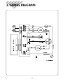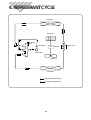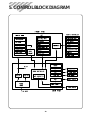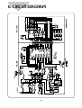
1
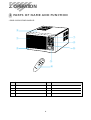
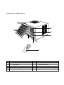
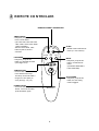
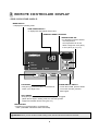
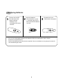
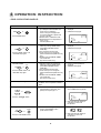
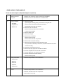
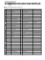
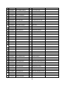
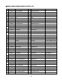
Service Manual
Window Type
Room Air Conditioner
Model: DWB-180RH-R
DWB-186RH-R
DWB-240RH-R
DWB-246RH-R
DAEWOO ELECTRONICS CORP.
Contents
CONTENTS
1. Specifications ................................................................................................2
2. Operation .....................................................................................................3
3. Wiring Diagram..........................................................................................18
4. Refrigerant Cycle .........................................................................................19
5. Control Block Diagram.................................................................................20
6. Circuit Diagram..........................................................................................21
7. Trouble Shooting Guide ...............................................................................24
8. Key Components of Electronic Circuit ............................................................33
9. Disassembly Instructions ...............................................................................35
10. Exploded Diagram and Parts List...................................................................37
1. SPECIFICATIONS
MODEL
ITEM
DWB-180RH-R
DWB-186RH-R
DWB-240RH-R
DWB-246RH-R
Power Source
V/Ph/Hz
Capacity
(Cooling & Heating)
Btu/h
18,000
24,000
Kcal/h
4,530
6,048
Dehumidification
l/h
Electrical
Data
AC 220-240V / 1 / 50Hz
2.10
Power
Cooling
2,240
2,750
Input(W)
Heating
1,880
2,350
Running
Cooling
10.40
13.10
Current(A) Heating
8.80
11.40
Type
Model
Recipro
H2EB243ABKC
H2EB283ABKC
35µF/400VAC
40µF/370VAC
Compressor
Capacitor
Overload Protector
Model
Capacitor
Internal Type
AM12DWD08(D.M.I)
A2945CA011(D.M.I)
7.5µF/400VAC
7.5µF/400VAC
Fan Motor
Indoor-Fan
Blower Fan
Outdoor-Fan
Propeller Fan
Control
Refrigerant (R-22)
Capillary Tube
Amount (g)
Capillary
ID ø1.4 x L800 x 2
ID ø 1.6 x L1000 x 2
1,230
1,080
Unit (mm)
660 x 430 x 705
Packing (mm)
711 x 525 x 757
Dimensions (WxHxD)
Net Weight
65
67
Gross Weight
69
71.5
Weight (Kg)
Conditions by JIS C9812
2
2. OPERATION
1 PARTS OF NAME AND FUNCTION
• DWB-180RH-R/DWB-240RH-R
3
7
1
4
8
2
5
6
NO
PART NAME
NO
1
AIR FILTER
5
PANEL CONTROL
2
GRILL FRONT
6
REMOTE CONTROLLER
3
CABINET
7
BLADE HORIZENTAL
4
BLADE VERTICAL
8
AIR VENT
3
PART NAME
• DWB-186RH-R / DWB-246RH-R
3
7
2
4
8
1
5
9
6
NO
PART NAME
NO
1
AIR FILTER
6
REMOTE CONTROLLER
2
INLET GRILLE
7
BLADE HORIZENTAL
3
CABINET
8
AIR VENT
4
BLADE VERTICAL
9
GRILLE FRONT
5
PANEL CONTROL
4
PART NAME
2 REMOTE CONTROLLER
REMOCON SIGNAL TRANSMITTER
TIMER/CANCEL
• Everytime you push this button,
timer is set as follow.
(1Hr→2Hr→3Hr→4Hr→5Hr→6Hr
→8Hr→10Hr→12Hr→16Hr→20Hr
→24Hr→CANCEL).
After the unit is timed, if this
button is pushed, timer is
canceled.
TIMER/
CANCEL
FAN SPEED
AUTO
SWING
FAN SPEED
• Everytime you push this
button, it is selected as follow.
(Low→High→Low)
TEMP
TEMPERATURE
• It is the button to set the room
in the desired room temp.
The temp. can be set within a
range from 16°C (60°F) to
32°C (90°F) by 1°C (1°F)
SLEEP
• SLEEP mode is selected as
follow. (L1→L2→Cancel)
SLEEP
MODE
MODE
• Everytime you push this
button, it is selected as
follow.
(COOLING→HEATING→
FAN→COOLING)
AUTO SWING
• Everytime you push this
button, the auto swing
mode is toggled.
POWER ON/OFF
• To turn the unit ON, push this
button. To turn the unit OFF,
push this button, again.
5
3 REMOTE CONTROLLER DISPLAY
• DWB-180RH-R/DWB-240RH-R
MODE DISPLAY
• It displays the operating mode.
TEMP./TIMER DISPLAY
• It displays the temperature and the timer.
REMOCON SIGNAL RECEIVER
TEMPERATURE SET
• It is the button to set the desired
room temperature.
The temperature can be set
within a range from 16°C (60°F)
to 32°C (90°F) by 1°C (1°F)
SENSOR
Room Air-conditioner
FAN
TEMP
HEATING
COOLING
MODE
TIMER
FAN
SPEED
AUTO
SWING
FAN SPEED
• Everytime you push this button, It is selected as
follow. (Low→High→Low)
POWER
POWER ON/OFF SWITCH
• To turn the unit ON, push this button.
To turn the unit OFF, push this
button again.
AUTO SWING
• Everytime you push this button, the auto swing mode is toggled.
(When the fan stops in heating mode, the auto swing is also
stopped and restarts when the fan goes run.)
MODE SELECT
• Everytime you push this button, It is selected as
follow. (COOLING→HEATING→FAN→COOLING)
CAUTION: When you turn off the unit with cooling mode, the Fan still work for about 10 seconds.
6
• DWB-186RH-R / DWB-246RH-R
MODE DISPLAY
• It displays the operating mode.
TEMP./TIMER DISPLAY
• It displays the temperature and the timer.
REMOCON
SIGNAL
RECEIVER
TEMPERATURE SET
• It is the button to set the desired
room temperature.
The temperature can be set
within a range from 16°C (60°F)
to 32°C (90°F) by 1°C (1°F)
SENSOR
Room Air-conditioner
FAN
TEMP
HEATING
COOLING
MODE
TIMER
FAN
SPEED
AUTO
SWING
FAN SPEED
• Everytime you push this button, It is selected as
follow. (Low→High→Low)
POWER
POWER ON/OFF SWITCH
• To turn the unit ON, push this button.
To turn the unit OFF, push this
button again.
AUTO SWING
• Everytime you push this button, the auto swing mode is toggled.
(When the fan stops in heating mode, the auto swing is also stopped and restarts when the
fan goes run.)
MODE SELECT
• Everytime you push this button, It is selected as
follow. (COOLING→HEATING→FAN→COOLING)
CAUTION: When you turn off the unit with cooling mode, the Fan still work for about 10 seconds.
7
Replacing Batteries
1
Remove the COVER
from the back of the
remote controller.
• Slide the cover
according to the arrow
direction
2
Insert two battaries.
• Be sure that the (+) and
(–) directions are correct
• Be sure that both batteries
are new
–
+
3
Re-attach the cover.
• Slide it back into position
+
–
• Do not use rechargeable batteries such batteries differ from standard dry cells in shape,
dimensions and performance.
• Remove the batteries from the remote controller if the air conditioner is not going to be used for
an extended length of time.
8
4 OPERATION INSTRUCTION
• DWB-180RH-R/DWB-240RH-R
FUNCTION
DISPLAY
OPERATION
1. The unit starts working.
(It is delayed 30 seconds after main
power source is supplied.)
when running the unit again after
once having stopped it, please wait
for over 3 minutes.
2. Default mode is ‘COOLING’ mode.
3. Default desired room temperature is
‘26°C’ (79°F).
And fan speed is ‘Low’.
1. Current room temperature is
displayed.
2. ‘COOLING’ lamp lights.
1. Operating modes are changed as
follows by pushing “MODE” button.
(COOLING→HEATING→FAN→
COOLING)
2. The compressor and fan work.
3. In this mode you can change fan
speed and desired temperature at any
time.
4. SLEEP mode and ON/OFF TIMER
can be selected.
(By remocon button only)
1. Current room temperature is
displayed.
2. ‘HEATING’ lamp lights.
FAN Delay in heating mode
There are 10 seconds time delay of the
Fan Motor, when compressor is starts or
stops.
no display
Change desired room temperature
1. The desired room temperature is
changed within a range from 16°C
(60°F) to 32°C (90°F) by 1°C.
1. It display desired room temperature
when ‘TEMP’ button is pushed.
POWER ON
POWER
or
Push POWER button
COOLING MODE
MODE
or
MODE
Push the ‘MODE’ button until
‘COOLING’ lamp lights.
HEATING MODE
MODE
or
MODE
Push the ‘MODE’ button until
‘HEATING’ lamp lights.
TEMP
FAN
ROOM TEMP
HEATING
DESIRED TEMP
COOLING
TIMER
FAN
ROOM TEMP
HEATING
DESIRED TEMP
COOLING
TIMER
FAN
ROOM TEMP
HEATING
DESIRED TEMP
COOLING
TIMER
or
TEMP
Push the ‘TEMP▲▼’ button.
FAN
ROOM TEMP
HEATING
DESIRED TEMP
COOLING
TIMER
3. After a few seconds, display is
changed to current room
temperature.
Change ‘FAN SPEED’
FAN SPEED
FAN
SPEED
or
1. FAN SPEED is changed as follows by
pushing “FAN SPEED” button.
(LOW→HIGH→LOW)
1. It displays as follows.
LOW
HIGH
2. After a few seconds, display is
changed to current room
temperature.
Push the ‘FAN SPEED’ button.
9
FUNCTION
FAN MODE
MODE
MODE
or
OPERATION
1. The Fan works only.
2. In this mode, the unit circulate room
air.
3. Fan speed can be changed.
Push the ‘MODE’ button until
‘FAN’ lamp lights.
ON/OFF AUTO SWING
AUTO
SWING
AUTO
SWING
or
Push the ‘AUTO SWING’ button.
OFF TIMER
TIMER/
CANCEL
Push the ‘TIMER/CANCEL’
button when unit is working.
(REMOCON ONLY)
DISPLAY
1. Current room temperature is
displayed.
2. ‘FAN’ lamp lights.
FAN
ROOM TEMP
HEATING
DESIRED TEMP
COOLING
TIMER
1. Auto swing function is toggled.
2. Air out-flow direction is changed
automatically. (left/right direction)
3. While the fan stops in heating
mode, the auto swing is also
stopped and restarts when the fan
goes run.
There is no change in display.
1. Timer is set to as follows by pushing
“TIMER/CANCEL” button.
(1hr→2hr→3hr→4hr→5hr→6hr→8hr
→10hr→12hr→16hr→20hr→
24hr→cancel)
1. ‘TIMER’ lamp lights.
2. Setting time is displayed.
2. Unit is off after timer is over.
3. If you want to cancel timer, push
this button again at any time.
FAN
ROOM TEMP
HEATING
DESIRED TEMP
COOLING
TIMER
3. After a few seconds, display is
changed to current room
temprature.
FAN
ROOM TEMP
HEATING
DESIRED TEMP
COOLING
TIMER
4. At this time, operation mode is
displayed current setting mode.
10
FUNCTION
ON TIMER
TIMER/
CANCEL
Push the ‘TIMER/CANCEL’
button when unit is off.
(REMOCON ONLY)
SLEEP MODE
SLEEP
Push the ‘SLEEP’ button in
‘COOLING’ mode and
HEATING MODE. (REMOCON
ONLY)
DISPLAY
OPERATION
1. Timer is changed to as follows by
pushing “TIMER/CANCEL” button.
(1hr→2hr→3hr→4hr→5hr→6hr→8hr
→10hr→12hr→16hr→20hr→
24hr→cancel)
2. The unit starts working after set time
is over. (by the operation mode and
last setting temperature before the
unit is off.)
3. If you want to cancel timer, push this
button again at any time.
1. ‘TIMER’ lamp lights.
2. Setting time is displayed.
1. SLEEP MODE is changed as follows
by pushing “SLEEP” button.
(L1→L2→Cancel)
* L1 Mode
– The unit is off after 4 hours.
– The desired Temp is increased 3°C
(5.4°F) for 4 hours in Cooling mode.
– The desired temp is decreased 3°C
(5.4°F) for 4 hours in heating mode.
– Auto swing is selected.
– Fan speed is set to ‘LOW’.
* L2 Mode
– The unit work; as follow
1. ‘L1’ or ‘L2’ is displayed.
– Auto swing is selected.
– Fan speed is set to ‘LOW’.
2. This mode can be selected in
‘COOLING’ and ‘HEATING’ mode
only.
• ROOM TEMPERATURE DISPLAY.
Over 45°C or 100°F
5°C~45°C or 41°F~99°F
DISPLAY TEMPERATURE
Below 5°C (41°F)
11
ROOM TEMP
HEATING
DESIRED TEMP
COOLING
TIMER
3. After a few seconds, display is
changed to current room
temperature.
Defrost the heat-exchanger of
the outside (in heating mode)
The unit runs 50 minutes
The unit will start defrost function when
the temperature of the heat exchanger
of the outside arrived at the programed
temperature.
If not arrived at the programed
temperature, the unit continuousiy runs
the heating mode.
While the defrost function is working
the unit runs cooling cycle but the fan
stops.
FAN
no display
• DWB-186RH-R / DWB-246RH-R
FUNCTION
DISPLAY
OPERATION
1. The unit starts working.
(It is delayed 30 seconds after main
power source is supplied.)
when running the unit again after
once having stopped it, please wait
for over 3 minutes.
2. Default mode is ‘COOLING’ mode.
3. Default desired room temperature is
‘26°C’ (79°F).
And fan speed is ‘LOW’.
1. Current room temperature is
displayed.
2. ‘COOLING’ lamp lights.
1. Operating modes are changed as
follows by pushing “MODE” button.
(COOLING→HEATING→FAN→
COOLING)
2. The compressor and fan work.
3. In this mode you can change fan
speed and desired temperature at any
time.
4. SLEEP mode and ON/OFF TIMER
can be selected.
(By remocon button only)
1. Current room temperature is
displayed.
2. ‘HEATING’ lamp lights.
FAN Delay in heating mode
There are 10 seconds time delay of the
Fan Motor, when compressor is starts or
stops.
no display
Change desired room temperature
1. The desired room temperature is
changed within a range from 16°C
(60°F) to 32°C (90°F) by 1°C.
1. It display desired room temperature
when ‘TEMP’ button is pushed.
POWER ON
or
POWER
Push POWER button
COOLING MODE
MODE
or
MODE
Push the ‘MODE’ button until
‘COOLING’ lamp lights.
HEATING MODE
MODE
or
MODE
Push the ‘MODE’ button until
‘HEATING’ lamp lights.
TEMP
FAN
ROOM TEMP
HEATING
DESIRED TEMP
COOLING
TIMER
FAN
ROOM TEMP
HEATING
DESIRED TEMP
COOLING
TIMER
FAN
ROOM TEMP
HEATING
DESIRED TEMP
COOLING
TIMER
or
TEMP
Push the ‘TEMP▲▼’ button.
FAN
ROOM TEMP
HEATING
DESIRED TEMP
COOLING
TIMER
3. After a few seconds, display is
changed to current room temperature.
Change ‘FAN SPEED’
FAN SPEED
FAN
SPEED
or
1. FAN SPEED is changed as follows by
pushing “FAN SPEED” button.
(LOW→HIGH→LOW)
1. It displays as follows.
LOW
HIGH
2. After a few seconds, display is
changed to current room temperature.
Push the ‘FAN SPEED’ button.
12
FUNCTION
FAN MODE
MODE
MODE
or
OPERATION
1. The Fan works only.
2. In this mode, the unit circulate room
air.
3. Fan speed can be changed.
Push the ‘MODE’ button until
‘FAN’ lamp lights.
ON/OFF AUTO SWING
AUTO
SWING
AUTO
SWING
or
Push the ‘AUTO SWING’ button.
OFF TIMER
TIMER/
CANCEL
Push the ‘TIMER/CANCEL’
button when unit is working.
(REMOCON ONLY)
DISPLAY
1. Current room temperature is
displayed.
2. ‘FAN’ lamp lights.
FAN
ROOM TEMP
HEATING
DESIRED TEMP
COOLING
TIMER
1. Auto swing function is toggled.
2. Air out-flow direction is changed
automatically. (left/right direction)
3. While the fan stops in heating
mode, the auto swing is also
stopped and restarts when the fan
goes run.
There is no change in display.
1. Timer is set to as follows by pushing
“TIMER/CANCEL” button.
(1hr→2hr→3hr→4hr→5hr→6hr→8hr
→10hr→12hr→16hr→20hr→
24hr→cancel)
1. ‘TIMER’ lamp lights.
2. Setting time is displayed.
2. Unit is off after timer is over.
3. If you want to cancel timer, push
this button again at any time.
FAN
ROOM TEMP
HEATING
DESIRED TEMP
COOLING
TIMER
3. After a few seconds, display is
changed to current room
temprature.
FAN
ROOM TEMP
HEATING
DESIRED TEMP
COOLING
TIMER
4. At this time, operation mode is
displayed current setting mode.
13
FUNCTION
ON TIMER
TIMER/
CANCEL
Push the ‘TIMER/CANCEL’ button
when unit is off. (REMOCON ONLY)
SLEEP MODE
SLEEP
Push the ‘SLEEP’ button in
‘COOLING’ mode and HEATING
MODE. (REMOCON ONLY)
DISPLAY
OPERATION
1. Timer is changed to as follows by pushing
“TIMER/CANCEL” button.
(1hr→2hr→3hr→4hr→5hr→6hr→8hr→10hr
→12hr→16hr→20hr→24hr→cancel)
2. The unit starts working after set time is
over. (by the operation mode and last
setting temperature before the unit is off.)
3. If you want to cancel timer, push this
button again at any time.
1. ‘TIMER’ lamp lights.
2. Setting time is displayed.
1. SLEEP MODE is changed as follows by
pushing “SLEEP” button.
(L1→L2→Cancel)
* L1 Mode
– The unit is off after 4 hours.
– The desired Temp is increased 3°C
(5.4°F) for 4 hours in Cooling mode.
– The desired temp is decreased 3°C
(5.4°F) for 4 hours in heating mode.
– Auto swing is selected.
– Fan speed is set to ‘LOW’.
* L2 Mode
– The unit work; as follow
1. ‘L1’ or ‘L2’ is displayed.
The unit runs 50 minutes
The unit will start defrost function when the
temperature of the heat exchanger of the
outside arrived at the programed
temperature. If not arrived at the programed
temperature, the unit continuousiy runs the
heating mode.
While the defrost function is working the unit
runs cooling cycle but the fan stops.
• ROOM TEMPERATURE DISPLAY.
Over 45°C or 100°F
5°C~45°C or 41°F~99°F
DISPLAY TEMPERATURE
Below 5°C (41°F)
14
ROOM TEMP
HEATING
DESIRED TEMP
COOLING
TIMER
3. After a few seconds, display is changed
to current room temperature.
– Auto swing is selected.
– Fan speed is set to ‘LOW’.
2. This mode can be selected in ‘COOLING’
and ‘HEATING’ mode only.
Defrost the heat-exchanger of the
outside (in heating mode)
FAN
no display
5 DESCRIPTION OF FUNCTIONS
OFF-Timer
If you set time in OFF-Timer Mode, the unit will stop at the set time.
ON
Unit ON
Unit OFF
OFF
SET Time
HOUR
ON-Timer
If you set time in ON-Timer Mode, the unit will run at the set time.
Unit ON
ON
OFF
Unit OFF
SET Time
HOUR
Control of Room Temperature
(1) Range of setting temperature: 16~32°C
(2) Setting temperature: Operating temperature of compressor
COMP (ON)
COMP (ON)
COMP (OFF)
-1˚C
COMP (OFF)
Desired
temperature
+1˚C
Room
Temperature
Desired
temperature
(COOLING)
+3˚C
Room
Temperature
(HEATING)
Buzzer
If the Unit Display receive the signal of Remote Controller, you can hear the signal "beep –" or "beep, beep".
15
Fan Speed
(1) Motor speed (high speed, low speed).
(2) Remote controller setting fan speed. (H, L)
(3) Relation of operating mode between fan speed.
FAN ONLY
COOL
HEAT
H
H
H
H
L
L
L
L
Sleep Mode
(1) When you are going to sleep, select sleep button in remocon and the unit controls the room to the desired
temperature. (The unit will not operate after 4 hour)
(2) For changing the temperature.
• L1 Mode (Cooling)
Difference
desired temperature
between room
temperature (°C)
0.5°C
1°C
Desired
Temperature
0.5°C
1°C
1
0.5°C
1°C
0
0.5
SET TIME
1.0
HOUR
• The unit will not operate after 4 hour.
• L1 Mode (Heating)
Difference
desired temperature
between room
temperature (°C)
1°C
Desired
Temperature
1°C
1°C
0
0.5
1.0
HOUR
SET TIME
• The unit will not operate perfectly after 4 hour.
• L2 Mode (Cooling)
• L2 Mode (Heating)
• The unit will not operate perfectly after 10 hour.
• The unit will not operate perfectly after 10 hour.
(3) To cancel sleep mode, press the SLEEP button again or press the MODE button once. : the SLEEP indicator will
disappear in the display.
16
3min. Time Delay of Compressor
In normal operation, there is a time delay of three minutes between turn off and turning back on including
initial power up. (but when the unit resets the time delay is 30 seconds)
Auto Swing
(1) When you push this button, in remocon the left/right flap move to the position of keeping the room temperature
comiortable.
(2) The air discharge direction procedure is below.
Auto swing
Fixed
DE-ICE OPERATION
Entering de-ice operation(to turn cooling cycle).
1. The micro-computer chip is check the temperature of condensor, After 50 minutes since the units starts on heating mode.
2. If the Temperature is below -4˚C, the De-ice function will start.
3. Now, the unit turned to cooling operation but fan motor is off.
Back to heat mode.
1. On the de-ice operation if the temperature is going over 15˚C.
2. Or 15minutes passed on the de-ice operation.
3. Now the unit turned to heating mode.
Remark: This de-ice operation is always repeat in heating mode when satisfying of the condition to enter the de-ice
operation.
50minutes
15minutes
Time
ON
Compressor
(Heater sump)
Fan motor
(Reversing valve)
(Lamp)
ON
ON
OFF
Sensing
Temperature
(-4¡C)
(15¡C)
Self-Diagnostic Function
The control will contain diagnostic test to verify the integrity of the system.
(1)Error Code Display
ERROR CODE
88 LED DISPLAY
ERROR CONTENTS
1
• Room air thermistor open.
• Heat exchanger thermister open
2
• Room air thermister short
• Heat exchanger thermister short
17
3. WIRING DIAGRAM
18
4. REFRIGERANT CYCLE
Evaporator
Blower fan
Reversing
Valve
Accumulator
M
MOTOR
Compressor
Propeller fan
Condenser
Refrigerant flow(COOLING)
Refrigerant flow(HEATING)
19
Capillary Tube
5. CONTROL BLOCK DIAGRAM
20
6. CIRCUIT DIAGRAM
21
✔ Caution : In this Service Manual, some parts can be changed for improving, their performance without notice in the
parts list. So, if you need the latest parts information, please refer to PPL(Parts Price List) in Service
Information Center (http://svc.dwe.co.kr).
Part List
● MAIN PCB ASS’Y(3114306800)
NO
PART NAME
SPEC
PART CODE
Q’TY
REMARK
1
2
3
4
5
6
7
8
9
10
11
12
13
14
15
16
17
18
19
20
21
22
23
24
25
26
27
28
29
30
31
32
33
34
35
36
37
38
39
40
41
42
43
44
45
46
47
48
49
50
51
52
53
54
55
56
57
58
59
60
61
BUZZER
C-CERA
C-CERA
C-CERA
C-CERA
C-CERA
C-CERA
C-CERA
C-CERA
C-ELEC
C-ELEC
C-ELEC
C-ELEC
C-ELEC
C-ELEC
C-LINE ACROSS
FUSE CLIP
PIN
WAFER
WAFER
WAFER
WAFER
WAFER
DIODE
DIODE
DIODE ZENOR
DIODE
DIODE
DIODE
DIODE
FUSE GLASS TUBE
IC REGULATOR
IC SMPS
IC DRIVER
IC MICOM
IC RESET
CHOKE COIL
RESONATOR
IC PHOTOCOUPLER
PCB MAIN
R CARBON FILM
JUMPER
R CARBON FILM
R CARBON FILM
R CARBON FILM
R CARBON FILM
R CARBON FILM
R CARBON FILM
R CARBON FILM
R CARBON FILM
R METAL FILM
R CARBON FILM
R METAL FILM
SW RELAY
RELAY
RELAY
RELAY
RELAY
TRANS SMPS
VARISTOR
C CERA
DP-2520BA
104M 50VDC
104M 50VDC
104M 50VDC
104M 50VDC
104M 50VDC
103M 50VDC
103M 50VDC
104M 50VDC
10UF 450V SD
10UF 450V SD
100MF 16V SD
470MF 35V SD
4.7MF 50V SS
10MF 16V SS
275V 104K(PILKOR)
AFC-520
GP881206-2(250)
YW396-03AV
YPW500-04
SMW250-15,WHITE
SMW250-02
SMW250-02
ST02D-200
UF203
1N5241B
IN4007A
IN4007A
IN4007A
IN4007A
250V/50T 3.15A
L7805CV
TNY264P
ULN2004AP(M)
TMP87C809BN-4K75
KIA7042P 5L
1MH,0.5A
CRTL8.00MSOT
TLP421
80X130X1.6T,FR1
1/4 1K OHM J
10MM
1/4 10K OHM J
1/4 1K OHM J
1/4 1K OHM J
1/4 100 OHM J
1/4 1K OHM J
1/4 5.6K OHM J
1/4 1K OHM J
1/4 330 OHM J
1/4 10.0K OHM F
1/4 330 OHM J
1/4 10.0K OHM F
PCF-112-D-1M
US11-12S
US11-12S
US11-12S
US11-12S
264P,1916
15G561K/350V
2200PF,250V,Y1
3105698200
CCXE1H104M
CCXE1H104M
CCXE1H104M
CCXE1H104M
CCXE1H104M
CCXE1H103M
CCXE1H103M
CCXE1H104M
CEXE2W106C
CEXE2W106C
CEXE1C107C
CEXE1V477C
CEXE1C475A
CEXE1C106A
CLV-B3104M
3107000600
3108803500
3108802500
3108805500
3108806500
3108804200
3108804210
DZST02D200
DZUF203--DZN5241B-DZN4007A-DZN4007A-DZN4007A-DZN4007A-5FVLB3152L
1L7805CV-1TNY264P-13GT62004A
13GS4K75-1KA7042P-52C102K000
5PCRTL8MS0
1TLP421--3114306210
RD-4K102J3109400100
RD-4K103JRD-4K102JRD-4K102JRD-4K101JRD-4K102JRD-4K562JRD-4K102JRD-4K331JRN-4K1002F
RD-4K331JRN-4K1002F
5SC010141B
5SC0101310
5SC0101310
5SC0101310
5SC0101310
5EMU1916-D15G561K-CH1BFB222K
1
1
1
1
1
1
1
1
1
1
1
1
1
1
1
1
2
1
1
1
1
1
1
1
1
1
1
1
1
1
1
1
1
1
1
1
1
1
1
1
1
1
1
1
1
1
1
1
1
1
1
1
1
1
1
1
1
1
1
1
1
BZ1
CC1
CC2
CC3
CC4
CC5
CC6
CC7
CC8
CE1
CE2
CE3
CE4
CE5
CE6
CL1
CLIP
CN1
CN2
CN3
CN4
CN5
CN6
D1
D2
D3
D4
D5
D6
D7
FUSE
IC1
IC2
IC3
IC4
IC5
L1
OSC1
PC1
PCB
R1
R11
R12
R13
R2
R3
R4
R5
R6
R7
R8
R9
R10
RL1
RL2
RL3
RL4
RL5
TRS1
VAR
YC1
22
✔ Caution : In this Service Manual, some parts can be changed for improving, their performance without notice in the
parts list. So, if you need the latest parts information, please refer to PPL(Parts Price List) in Service
Information Center (http://svc.dwe.co.kr).
●Front PCB ASS’Y(3114306100)
LOC
CODE
PART NAME
SPEC
QTY
REMARK
1
2
3
4
5
6
7
8
9
10
11
12
13
14
15
16
17
18
19
20
21
22
23
24
25
26
27
28
29
30
31
32
33
34
CCXE1H103M
3108806600
DZN4148FTB
DZN4148FTB
DZN4148FTB
DDLG5031DDDLG5031DDDLG5031DDDLG5031D3114306110
RD-4K121JRD-4K121JRD-4K121JRD-4K121JRD-4K121JRD-4K121JRD-4K121JRD-4K103JRD-4K103J1354HF2--3103003700
3109300900
3109300900
3109300900
3109300900
3109300900
3109300900
TKRC102M-TZTC3198YTKRC102M-TZTC3198YTKRC102M-TZTC3198YTKRC102M--
C-CERA
WAFER
DIODE
DIODE
DIODE
LED
LED
LED
LED
PCB FRONT
R CARBON FILM
R CARBON FILM
R CARBON FILM
R CARBON FILM
R CARBON FILM
R CARBON FILM
R CARBON FILM
R CARBON FILM
R CARBON FILM
RECEIVER MODULE
LED SEGMENT
SWITCH TACT
SWITCH TACT
SWITCH TACT
SWITCH TACT
SWITCH TACT
SWITCH TACT
TR
TRANSISTOR
TR
TRANSISTOR
TR
TRANSISTOR
TR
103M 50VDC
SMAW250-15,WHITE
1N4148 AUTO 26MM
1N4148 AUTO 26MM
1N4148 AUTO 26MM
DLG-5031D(GRN)
DLG-5031D(GRN)
DLG-5031D(GRN)
DLG-5031D(GRN)
121X69.5X1.6T,FR1
1/4 120 OHM J
1/4 120 OHM J
1/4 120 OHM J
1/4 120 OHM J
1/4 120 OHM J
1/4 120 OHM J
1/4 120 OHM J
1/4 10K OHM J
1/4 10K OHM J
354HF2
DDG-5026M(CATHODE)
JTP1212
JTP1212
JTP1212
JTP1212
JTP1212
JTP1212
KRC 102-M (TAPPING)
KTC3198Y-(1815Y) (AUTO)
KRC 102-M (TAPPING)
KTC3198Y-(1815Y) (AUTO)
KRC 102-M (TAPPING)
KTC3198Y-(1815Y) (AUTO)
KRC 102-M (TAPPING)
1
1
1
1
1
1
1
1
1
1
1
1
1
1
1
1
1
1
1
1
1
1
1
1
1
1
1
1
1
1
1
1
1
1
CC1
CN1
D1
D2
D3
L1
L2
L3
L4
PCB
R1
R2
R3
R4
R5
R6
R7
R8
R9
RCV1
SEG1
SW1
SW2
SW3
SW4
SW5
SW6
TR1
TR2
TR3
TR4
TR5
TR6
TR7
●Remocon ASS’Y(3108402950)
NO
PART NAME
SPEC
PART CODE
Q’TY
REMARK
1
2
3
4
5
6
7
8
CASE-A
CASE-B
CUSHION KEY
SPRING A
SPRING B
COMMON SPRING
SCREW A
RESONATOR
ELEC
CONDENSOR
CHIP CONDENSOR
CHIP RESISTOR
CHIP RESISTOR
TRANSISTOR
LED IR
IC REMOCON
COVER BTRY
PCB REMOCON
HOLDER
REMOCON
ABS380
BAS380
SILICON 6U
SUS304
SUS304
SUS304
M1.9*6.5
RJ-455BL
3101100510
3101100600
3101405900
3105100600
3105100700
3105100800
3108495110
5ZAR455---
1
1
1
1
1
1
3
1
X1
10VB 47M
CEAF10475M
1
C1
CETMK212F221Z-T
1/10W 1.5 OHM
1/10W100K OHM
STN2222
SI5312-H
PT2221
ABS
FR-1
HCQD220MQ
HRFT159JCP
HRFT104JCP
TSTN2222DS5312-H-14EZPT2221
3101405900
3104302000
2
1
3
1
1
1
1
1
C2,3
R1
R2,3,4
Q1
IR1
U1
ABS
3103003400
1
9
10
11
12
13
14
15
16
17
18
23
7. TROUBLE SHOOTING GUIDE
TROUBLE
Fan motor and
compressor do not run
SITUATION
1. Power failure
ANALYSIS
CAUSE
REMEDY
1) Power plug
1) Power failure
● Consult
2) Circuit breaker
2) Circuit breaker is tripped
● In
your electric company
case of a breaker, turn it on
and off a few times
3) Power plug is not contacting
● Replace
2. Power is supplied,
but the equipment
does not run
the power plug
1) receptacle
● Disconnection
● Repair or replace the receptacle
2) Cord or lead wire to
the switch
1) Disconnection
● Replace
the cord or lead wire
2) Malfunction of contact
compressor does not
run
1) Compressor
● Disconnection
2) Thermister
1) Failure
or burned-out
1. Not operating at all
● Replace
the compressor or
connection wire
2) Malfunction
● Replace
3) Mode is not set to the proper
setting
● Repair
or replace
● Resetting
3) O.L.P
1) Turn over
● Wait
mode.
until return it.
● Replace
4) Capacitor
● Lack
of capacity
● Repair
● Disconnection
2. Compressor
1) Electricity
1) The voltage exceeded allowed
range
● Consult
● Check
2) Capacity of wire is not
sufficient
your electric company
the capacity of wire
● Ventilate
well and remove the
heat source
2) Room temperature
and outside
temperature
● Extremely
● Burned-out
● Replace
3) Compressor
● Malfunction
● Replace
4) O.L.P
● Lack
● Replace
high or Low
of capacity
5) Capacitor
3. Frequent start and
stop
1) Thermister
● Malfunction
● Replace
2) Capacitor
● Lack
of capacity
● Replace
3) O.L.P
● Turn
over
● Wait
24
until return it.
TROUBLE
SITUATION
ANALYSIS
CAUSE
1) Fan
2) Fan motor
3) Capacitor
4) Fan motor circuit
The compressor runs
but the motor doesn’t
run
● Blocked
by others
● Disconnection
or burned-out
REMEDY
● Repair
● Replace
the fan motor
electric cord
● Failure
malfunction of contact
● Disconnection
of malfunction of
● Replace
● Check
the circuit
contact
Both fan motor and
compressor are
running but cooling or
heating is bad
Not cooling at all
Not heating at all
Insufficient cooling or
heating
Refrigerant system
1) Refrigerant system
1) Refrigerant system is choked
● Repair
2) Compressor failure
● Repair
3) Leakage of refrigerant gas
● Recharge
1) Refrigerant system is choked
● Check
refrigerant gas
and repair refrigerant
system
2) Filter
2) Compressor failure
● Replace
3) Heat exchanger of
condenser
3) Leakage of refrigerant gas
● Check
a part of Leakage and
repair
4) Refrigerant charge is too high
● Repair
● Clogged
and recharge
up with dust
● Clean
the air fiter
● Clean
the unit
1) Fin is cogged up with dust
2) The ventilation is not good
● Shade
3) The unit is exposed to the
sunlight
the unit from the
sunlight
● Remove the added heat source
4) Other heat source is added in
the room
Vibration & Noise
1) Installation place
● Installation
● Install
2) Fan
1) Fan is contacted with
obstacles
● Remove
2) Fixing bolt
● Tighten
the bolt
● Have
● Tighten
the screw
of the unit is
imperfectly done
the unit perfectly
obstacles
3) Fixing screws
4) Electric
components
a screw loose
● Electrical
Water leakage into
room
● Installation
Electric shock
(Leakage of current)
● Insulation
condition
● The
of
components
25
noise
front is lower than rear side
● Exchange
the components
● Make
rear side of the unit lower
than the front
1)Insulation defect of wiring and
lead wire
● Check
the unit’s Leakage of
2) Leakgae of current due to the
dew or rust
● Replace
current.
the defective parts or
components
Self-Diagnostic Function
1) Error Code E1 or E2
1 Check the connector of room air thermistor. (or connecting wire)
2 Check soldering of connecting on control P.C.B. (Error of soldering or short)
3 Check the resistance of room air thermistor.
“Press the temperature Keys (Up & Down), Error code is displayed.”
Unit Not Run
The power is applied to the unit
Rating voltage
Check the voltage between “CN 1 ”
and
“RL1 N ” of Main P.C.B
under 90%
Check the
Breaker or Fuse
Rating voltage more than 90%
No
Check the unit display
is all off?
Yes
Press the ON/OFF button of
Remote Control or Front Panel
No
Self Diagnostic
function is ON
Yes
No
Check according to
self Diagnostic function
Is the unit display all off?
Main P.C.B defect
Pull out the power plug
and then insert the power plug
after 5 second
Main P.C.B is normal
Recheck from the beginning
26
Only Compressor Do not Run
- Check the following at cooling mode
Check the voltage between “CN 1 ”
and
“RL1 (COMP)” of Main P.C.B
Rating voltage
less than 90%
Check the Main P.C.B
the circuit for relay
driving.
Rating voltage more than 90%
Rating voltage
less than 90%
Check the compressor wiring
Check the connecting
wire between Main
P.C.B and the
compressor
Rating voltage more than 90%
Check the Relay(RL1)
NG
Change Relay(RL1)
Check the wiring of outdoor unit
Check the compressor
(Check the winding resistance)
Open or Short
OK
Check the compressor capacitor
27
Change the
compressor.
PCB DRIVING DESCRIPTION
1. Power Supply Circuit
DC 12V and DC 5V Power source circuit.
Diode D4~D7 : Rectifier Diodes
Condenser CE1 and CE2 : Smoothing circuit components.
DC 12V Power output is made by switching performance of Device IC2 and TRS1.
DC 12V Power is used for Relay and Buzzer driving.
DC 5V is regulated by IC1. It is used for LED display, Sensor, Key and Micom driving.
Regulation of DC12V is performed by PC1 and its voltage feedback signal.
And the others are generally used for noise consumption.
2. Reset Operation Circuit
Micom IC4 is operated by IC5 and its signal. Generally, DC5V is checked at port 27 of IC4.
R5 and CE5 : Parts for determine reset signal timing when the power is ON and OFF.
29
3. Sensor Signal Input Circuit and Option
Port 4 of IC4 is terminal of A/D converter input.
Room temperature is sensing by change of temperature resistance.
The input voltage is determined by ratio between R8 (10.0 KΩ) and Room sensor value.
Relation between temperature and input voltage is as following.
Temperature (°C)
Sensor resistance (KΩ)
Input Voltage (V)
-5
43.67
0.932
0
33.40
1.152
5
25.79
1.397
10
20.10
1.661
15
15.80
1.938
20
12.52
2.220
25
10.00
2.500
30
8.05
2.770
35
6.52
3.027
Port 10 of IC1 is a type of temperature display option port.
It is determined by ratio between R11 and R12.
Relation between R1 and Display temperature type is as following.
R11(KΩ)
Input Voltage(V)
Temperature display type
SHORT
0V
Centigrade (°C)
2.32
0.95V
Fahrenheit (°F)
30
4. Display drive and Key Input Circuit
Display operation is dynamic scan drive type. It has 1/3 duty cycle.
Scan signal output : Port 21, Port 22, Port 23
TR1~TR6 : Scan signal drive circuit
R1~R7 : LED current limit resistance .(for 6 high current output port 12,13,15,16,17,18)
Port 19, Port 24 of IC4 : Key signal input by scan.
Oscillatory frequency is 8MHz. It is made up resonator oscillatory frequency.
Oscillatory wave is sine wave shape.
The remote control signal input is detacted at port 5 of IC4.
CE6 and CC8 : Noise protection parts
31
5. Relay and Buzzer drive Circuit
Port 6,7,9 of IC4 : Relay ON and OFF drive signal output.
IC3 : Relay ON and OFF drive device.
Fan Motor ON/OFF and Speed control : RL2, RL3, RL4
Compressor ON/OFF control : RL1.
Swing Motor ON/OFF control : RL5
Buzzer is operated by Port 26 of IC4. Operative frequency is 2 KHz, 1/2 duty pulse.
32
8. KEY COMPONENTS OF ELECTRIC CIRCUIT
(1) IC4 (TMP87C809N) MICOM
(2) IC2 (TNY264) SMPS SWITCH IC
33
(3) U2(TD62004AP) DARLINGTON ARRAYS
IN1 1
IN2 2
IN3 3
IN4 4
IN5 5
IN6 6
IN7 7
GND 8
KID65004AP
16 OUT 1
15 OUT 2
14 OUT 3
13 OUT 4
12 OUT 5
11 OUT 6
10 OUT 7
9 COMMON FREE
WHEELING DIODES
COM
10.5K
7.2K
3K
(Equivalent Circuit)
(Top View)
(4) U7 (7805CT): VOLTAGE REGULATOR (5VDC)
TSUFFIX
PLAASTIC PACKAGE
CASE 221A
TO-220TYPE
SCHEMATIC DIAGRAM
INPUT
100K
500
100
100
10K
240
200
3.3
K
1
2
3
Pin 1. INPUT
2. GROUND
3. OUTPUT
1.4
K
OUTPUT
2K
6K
2.7
K
0.3
0.19K
28K
30pF
5K
500
6K 1K
34
5K
Fin 2 is ground
for Cose 221A.
Case is ground
for Case 1.
GND
9. DISASSEMBLY INSTRUCTIONS
• DWB-180RH-R/DWB-240RH-R
Please refer to the chapter 10 (Exploded diagram and parts list).
1
2
Before service of
1. Stop the unit, remove the power cord from the receptacles.
any part.
2. Move the unit to the safe location for the suitable work.
Ass’y Fan Motor
1. Remove Front Grille
- Fan Motor
- Remove Filter Pre.
- Propeller Fan
- Remove screw(2 point) in Front Grille.
- Blower Fan
2. Remove Cabinet from the unit.
- Remove screws (2 point) from the unit’s sides.
3. Remove Holder Scroll.
4. Remove Scroll upper
5. Remove Ass’y Control Box
- Remove screws (4 point).
- Remove wires in the each components.
6. Remove wires in the Panel Housing.
7. Remove screws (4 point) from Ass’y Fan Motor’s sides.
- Ass’y Fan Motor is assembly of Fan Motor, Propeller and Blower Fan,
Orifice and Panel Housing.
8. Lift the Ass’y Fan Motor from the unit.
9. Remove Clip Fan (2 point) from the shaft of Fan Motor.
10. Remove Propeller Fan from the shaft of Fan Motor.
11. Remove Blower Fan from the shaft of Fan Motor.
12. Remove Fan Motor from Panel Housing.
- Remove screws (4 point).
3
Ass’y Control Box
1. Same as the procedure 1 to 5 in the Item 2.
- Panel Control
- Main Pcb
- Front Pcb
- Capacitor
- Power Cord
4
O.L.P
1. Same as the procedure 1 to 2 in the Item 2.
2. Remove Terminal Cover from Compressor.
- Remove hex-nut (1 point).
35
• DWB-186RH-R / DWB-246RH-R
Please refer to the chapter 10 (Exploded diagram and parts list).
1
2
Before service of
1. Stop the unit, remove the power cord from the receptacles.
any part.
2. Move the unit to the safe location for the suitable work.
Ass’y Fan Motor
1. Remove Front Grille
- Fan Motor
- Open the grille upward by pulling out the bottom of the grille, lift it.
- Propeller Fan
- Remove screw which fasten Frame Grille with driver.
- Blower Fan
- Disassemble Frame Grille from chassis.
2. Remove the unit from Cabinet.
- Remove screws (2 point) from the unit’s sides.
- Pull the unit from cabinet
3. Remove Holder Scroll.
4. Remove Scroll upper
5. Remove Ass’y Control Box
- Remove screws (4 point).
- Remove wires in the each components.
6. Remove wires in the Panel Housing.
7. Remove screws (4 point) from Ass’y Fan Motor’s sides.
- Ass’y Fan Motor is assembly of Fan Motor, Propeller and Blower Fan, Orifice
and Panel Housing.
8. Lift the Ass’y Fan Motor from the unit.
9. Remove Clip Fan (2 point) from the shaft of Fan Motor.
10. Remove Propeller Fan from the shaft of Fan Motor.
11. Remove Blower Fan from the shaft of Fan Motor.
12. Remove Fan Motor from Panel Housing.
- Remove screws (4 point).
3
Ass’y Control Box
1. Same as the procedure 1 to 5 in the Item 2.
- Panel Control
- Main Pcb
- Front Pcb
- Capacitor
- Power Cord
4
O.L.P
1. Same as the procedure 1 to 2 in the Item 2.
2. Remove Terminal Cover from Compressor.
- Remove hex-nut (1 point).
10. EXPLODED DIAGRAM AND PARTS LIST.
■ DWB-180RH-R/DWB-240RH-R PARTS LIST
No.
CODE
1
3100066221
ASS'Y PAN BASE
1
DWB-180CH-R H/P
2
3106002200
COMP BOLT
3
M8*L41.6(OD 10)
3
3100002900
ASS'Y SEAL CAP DRAIN
1
SEAL C/DRAIN ASSY
4
3106600910
SCROLL LOWER
1
EPS H/P
5
3106700400
CAM
1
POM
6
3104600110
RING VENT
1
NBR P6
7
3101700300
LEVER VENT
1
PP(LG, H-540)
8
3100066510
ASS'Y EVAPORATOR
1
DWB-180CH-R, 4R-4C, H/P, 1.8
9
3100074001
AS PIPE EVA OUT
1
DWB-180CH-R, H/P
10
3100074101
AS PIPE EVA IN
1
DWB-180CH-R, H/P
3100073001
AS PIPE CAPILLARY
1
DWB-180CH-R, H/P
DWB-180RH-R
3100073010
AS PIPE CAPILLARY
1
DWB-240CH-R, H/P
DWB-240RH-R
12
3104431501
PIPE COND
1
OD 9.52*T0.7
13
3106600810
SCROLL UPPER
1
EPS H/P
3117103600
COMPRESSOR
1
H2EB243ABKC 220/240V 20.3K
DWB-180RH-R
3117103700
COMPRESSOR
1
H2EB283ABKC 220/240V 50HZ
DWB-240RH-R
15
7400208412
WASHER PLAIN
3
ID 8.4 * OD 26 * T1.6
16
7392801211
NUT LOCK
3
M8*1.25P
17
GROMMET
3
EPDM
COMP ACCESSORY PART
18
GASKET
1
SILICON
COMP ACCESSORY PART
19
COVER TERMINAL
1
11
14
COMPONENTS
Q’TY
SPECIFICATION
REMARK
COMP ACCESSORY PART
20
3112709710
HARNESS COMP2
1
#14 AWG*3(DWB-180C-R)
21
3107000500
FAN CLIP
2
SK-5
22
3101802800
FAN BLOWER
1
ABS(ABS-730)
23
3104202301
PANEL HOUSING
1
SGCC T1.0 DWB-180C
25
3101406502
COVER SCROLL
1
SGCC T0.6
26
3101406601
COVER SIDE
1
SGCC T0.6
3108005411
FAN MOTOR
1
A2938CA010
DWB-180RH-R
3108005511
FAN MOTOR
1
A2945CA012
DWB-240RH-R
28
3100701500
BUSHING GUIDE
1
NBR
29
7S432X5121
SPECIAL SCREW
4
TT3 HEX 5X12 STAR MFZN
30
3110096200
ASS'Y COVER ORIFICE
1
DWB-180C-R
31
3103800500
LOCK WIRE-STANDOFF
2
DAWS 116
3101802901
FAN PROPELLER
1
ABS+GF20% NATURAL
DWB-180RH-R
3101802900
FAN PROPELLER
1
ABS+GF20% (PIE 8.0)
DWB-240RH-R
33
3100058250
ASS'Y CABINET WL
1
DWB-184C-R
34
3108505301
SEAL CABINET TOP(F)
1
F-US+660*T5*50
35
3108505360
SEAL CABINET TOP( R )
1
F-US+660*T5*110
27
32
37
No.
CODE
36
3108505501
SEAL CABINET SIDE( R )
1
F-US+130*T10*370
37
3108505401
SEAL CABINET SIDE(L)
1
F-US+200*T10*370
38
3108505600
SEAL COND TOP
1
F-US+70*T5*560
39
3100066310
ASS'Y CONDENSER
1
DWB-180CH-R 3R-2C H/P 2.0
40
3100070811
AS PIPE COND IN
1
DWB-180CH-R H/P
41
3100070911
AS PIPE COND OUT
1
DWB-180CH-R H/P
42
3104431300
PIPE 4-WAY EVA
1
C1220T-0L OD 12.7*T0.7
43
3100074601
AS PIPE DISCHARGE
1
DWB-180CH-R H/P
44
3100074501
AS PIPE SUCTION
1
DWB-180CH-R H/P
3100067930
ASS'Y GRILLE FRONT
1
DWA-180R
3100072500
AS SEAL G/FRONT(2)
1
DWA-240C-R D/GRY
46
3108505230
SEAL GRILLE FRONT(3)
47
3106502202
BLADE VERTICAL
1
HIPS(HI-450) 18K,24K
48
3106502100
BLADE HORIZENTAL
2
PP(LG, H-540)
49
3101902201
FILTER PRE
1
HIPS+MESH #PP32
50
3101601520
DECO FRONT
2
NEW PCB(DWB-180RH-R)
51
3100509211
BOX CONTROL
1
SGCC T0.8 ELECTRO TYPE
52
3102709920
HARNESS OD SENSOR
1
TSD310DAACX15
53
3100075800
ASS'Y CABINET DRAIN
1
DWB-180CH-R
56
3966031000
SWING MOTOR
1
200/220V 50/60 HZ(DS-090R)
57
7112300611
SCREW TAPPING
2
T1. TRS M3*6
3109504500
CAPACITOR
1
7.5+35µF 400VAC D63(SH)
DWB-180RH-R
3116904400
CAPACITOR
1
7.5+40µF 400VAC
DWB-240RH-R
59
3101201500
CLAMP CAPACITOR
1
SGCC-M-Z22(LG)
60
7122401011
SCREW TAPTITE
1
T1 TRS 4*10
61
3101300430
POWER CORD
1
SJT(AWG#14*3) ARABIA
62
3101201900
CLAMP POWER CORD
1
DA-6N
63
7122401011
SCREW TAPTITE
1
T1 TRS 4*10
64
3108505801
SEAL CONTROL BOX
1
F-PE 210*160*T2
65
3105000100
SPACER LOCKING
4
DABS-8R
66
3105000110
SPACER BOARD
1
DACBS-8R
67
3114306100
ASS'Y FRONT PCB
1
DWC-125,184,240R,240RH(12K.)
68
3108402900
ASS'Y REMOCON
1
SIMPLE WINDOW T. 12/15K
69
5EPU040100
TRANSFORMER
1
DWA-230V 220/14.5V 0.3A
70
3104202500
PANEL CONTROL
1
HIPS(HI-450,L-GRAY)
71
3102708510
HARNESS DISPLAY
1
15*26 AWG
72
3102709930
HARNESS COIL SENSOR
1
10KΩ, 1200mm, 3P
73
3114306800
ASS'Y MAIN PCB
1
DWC-184,240RH-R(HP/18,24K)
3113522200
LABEL SPEC
1
DWB-180RH-R
3113516110
LABEL SPEC
1
DWB-240RH-R
3113516201
MANUAL OWNER'S
1
45
58
74
75
COMPONENTS
Q’TY
SPECIFICATION
REMARK
F-PE
38
■ DWB-186RH-R/DWB-246RH-R PARTS LIST
No.
CODE
1
3100066221
ASS'Y PAN BASE
1
DWB-180CH-R H/P
2
3106002200
COMP BOLT
3
M8*L41.6(OD 10)
3
3100002900
ASS'Y SEAL CAP DRAIN
1
SEAL C/DRAIN ASSY
4
3106600910
SCROLL LOWER
1
EPS H/P
5
3106700400
CAM
1
POM
6
3104600110
RING VENT
1
NBR P6
7
3101700300
LEVER VENT
1
PP(LG, H-540)
8
3100066510
ASS'Y EVAPORATOR
1
DWB-180CH-R, 4R-4C, H/P, 1.8
9
3100074001
AS PIPE EVA OUT
1
DWB-180CH-R, H/P
10
3100074101
AS PIPE EVA IN
1
DWB-180CH-R, H/P
3100073001
AS PIPE CAPILLARY
1
DWB-180CH-R, H/P
DWB-186RH-R
3100073010
AS PIPE CAPILLARY
1
DWB-240CH-R, H/P
DWB-246RH-R
12
3104431501
PIPE COND
1
OD 9.52*T0.7
13
3106600810
SCROLL UPPER
1
EPS H/P
3117103600
COMPRESSOR
1
H2EB243ABKC 220/240V 20.3K
DWB-186RH-R
3117103700
COMPRESSOR
1
H2EB283ABKC 220/240V 50HZ
DWB-246RH-R
15
7400208412
WASHER PLAIN
3
ID 8.4 * OD 26 * T1.6
16
7392801211
NUT LOCK
3
M8*1.25P
17
GROMMET
3
EPDM
COMP ACCESSORY PART
18
GASKET
1
SILICON
COMP ACCESSORY PART
19
COVER TERMINAL
1
11
14
COMPONENTS
Q’TY
SPECIFICATION
REMARK
COMP ACCESSORY PART
20
3112709710
HARNESS COMP2
1
#14 AWG*3(DWB-180C-R)
21
3107000500
FAN CLIP
2
SK-5
22
3101802800
FAN BLOWER
1
ABS(ABS-730)
23
3104202301
PANEL HOUSING
1
SGCC T1.0 DWB-180C
25
3101406502
COVER SCROLL
1
SGCC T0.6
26
3101406601
COVER SIDE
1
SGCC T0.6
3108005411
FAN MOTOR
1
A2938CA010
DWB-186RH-R
3108005511
FAN MOTOR
1
A2945CA012
DWB-246RH-R
28
3100701500
BUSHING GUIDE
1
NBR
29
7S432X5121
SPECIAL SCREW
4
TT3 HEX 5X12 STAR MFZN
30
3110096200
ASS'Y COVER ORIFICE
1
DWB-180C-R
31
3103800500
LOCK WIRE-STANDOFF
2
DAWS 116
3101802901
FAN PROPELLER
1
ABS+GF20% NATURAL
DWB-186RH-R
3101802900
FAN PROPELLER
1
ABS+GF20% (PIE 8.0)
DWB-246RH-R
33
3100058250
ASS'Y CABINET WL
1
DWB-184C-R
34
3108505301
SEAL CABINET TOP(F)
1
F-US+660*T5*50
35
3108505360
SEAL CABINET TOP( R )
1
F-US+660*T5*110
36
3108505501
SEAL CABINET SIDE( R )
1
F-US+130*T10*370
37
3108505401
SEAL CABINET SIDE(L)
1
F-US+200*T10*370
38
3108505600
SEAL COND TOP
1
F-US+70*T5*560
27
32
39
No.
CODE
39
3100066310
40
3100070811
41
Q’TY
SPECIFICATION
ASS'Y CONDENSER
1
DWB-180CH-R 3R-2C H/P 2.0
AS PIPE COND IN
1
DWB-180CH-R H/P
3100070911
AS PIPE COND OUT
1
DWB-180CH-R H/P
42
3104431300
PIPE 4-WAY EVA
1
C1220T-0L OD 12.7*T0.7
43
3100074601
AS PIPE DISCHARGE
1
DWB-180CH-R H/P
44
3100074501
AS PIPE SUCTION
1
DWB-180CH-R H/P
45
3112201410
FRAME GRILLE
1
HIPS(WH1302A)
46
3112405800
GRILLE
1
HIPS(WH1302A)
47
3118401800
SEAL FRAME LEFT
1
F-PE
-
3118401500
SEAL FRAME BOTTOM
1
F-PE
-
3118401600
SEAL FRAME RIGHT
1
F-PE
-
3118401700
SEAL FRAME UPPER
1
F-PE
48
3116502000
BLADE VERTICAL
1
HIPS(WH1302A)
49
3116501900
BLADE HORIZENTAL
1
PP
50
3101902201
FILTER PRE
1
HIPS+MESH #PP32
51
3111602510
DECO FRONT
1
NEW PCB, GOLD, H/P
52
3100509211
BOX CONTROL
1
SGCC T0.8 ELECTRO TYPE
53
3102709920
HARNESS OD SENSOR
1
TSD310DAACX15
54
3100075800
ASS'Y CABINET DRAIN
1
DWB-180CH-R
56
3966031000
SWING MOTOR
1
200/220V 50/60 HZ(DS-090R)
57
7112300611
SCREW TAPPING
2
T1. TRS M3*6
3109504500
CAPACITOR
1
7.5+35µF 400VAC D63(SH)
DWB-186RH-R
3116904400
CAPACITOR
1
7.5+40µF 400VAC
DWB-246RH-R
59
3101201500
CLAMP CAPACITOR
1
SGCC-M-Z22(LG)
60
7122401011
SCREW TAPTITE
1
T1 TRS 4*10
61
3101300430
POWER CORD
1
SJT(AWG#14*3) ARABIA
62
3101201900
CLAMP POWER CORD
1
DA-6N
63
7122401011
SCREW TAPTITE
1
T1 TRS 4*10
64
3108505801
SEAL CONTROL BOX
1
F-PE 210*160*T2
65
3105000100
SPACER LOCKING
4
DABS-8R
66
3105000110
SPACER BOARD
1
DACBS-8R
67
3114306100
ASS'Y FRONT PCB
1
DWC-125,184,240R,240RH(12K.)
68
3108402900
ASS'Y REMOCON
1
SIMPLE WINDOW T. 12/15K
69
5EPU040100
TRANSFORMER
1
DWA-230V 220/14.5V 0.3A
70
3104202500
PANEL CONTROL
1
HIPS(HI-450,L-GRAY)
71
3102708510
HARNESS DISPLAY
1
15*26 AWG
72
3102709930
HARNESS COIL SENSOR
1
10KΩ, 1200mm, 3P
73
3114306800
ASS'Y MAIN PCB
1
DWC-184,240RH-R(HP/18,24K)
311359AQ00
LABEL SPEC 1
DWB-186RH-R
311359AR00
LABEL SPEC 1
DWB-246RH-R
3113913000
MANUAL OWNER'S
58
74
75
COMPONENTS
1
40
REMARK
■ DWB-180RH-R / DWB-240RH-R
41
■ DWB-186RH-R / DWB-246RH-R
42
DAEWOO ELECTRONICS CORP.
686, AHYEON-DONG MAPO-GU SEOUL, KOREA
C.P.O. BOX 8003 SEOUL, KOREA
TELEX: DWELEC K28177-8
CABLE: “DAEWOOELEC”
FAX: 02) 590-6291
TEL: 02) 360-7114/590-6151~5
http://www.dwe.co.kr
S/M NO.: DWB180RHR02
PRINTED DATE: JAN.2004