1
OB254-1.qxp
5/10/00 3:45 PM
Page 1
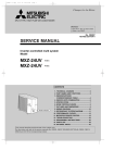
SPLIT-TYPE,HEAT PUMP AIR CONDITIONER
No. OB254
SERVICE MANUAL
Inverter-controlled multi system
Model
MXZ-32SV -
E1
CONTENTS
Model indication
1. TECHNICAL CHANGES ····································2
2. PART NAMES AND FUNCTIONS······················2
3. INDOOR/OUTDOOR
CORRESPONDENCE TABLE ···························3
4. INDOOR UNITS COMBINATION ·······················4
5. SPECIFICATION·················································8
6. NOISE CRITERIA CURVES ······························ 9
7. OUTLINES AND DIMENSIONS ······················ 10
8. WIRING DIAGRAM···········································11
9. REFRIGERANT SYSTEM DIAGRAM ··············12
10. PERFORMANCE CURVES ······························13
11. MICROPROCESSOR CONTROL·····················19
12. TROUBLESHOOTING······································25
13. DISASSEMBLY INSTRUCTIONS·····················36
14. PARTS LIST······················································39
15. OPTIONAL PARTS···········································42
This manual describes technical data of outdoor unit.
For indoor unit refer to the service manuals No. OB229, OB227 REVISED EDITION-B, OB252, OB212, OB239
and OC165 of corresponding models.
OB254-1.qxp
1
5/9/00 11:58 AM
Page 2
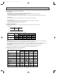
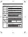
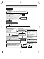
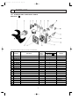
TECHNICAL CHANGES
MXZ-32RV - E1
➔ MXZ-32SV - E1
1. The combination pattern of the indoor unit has increased.
2. Crankcase heater has disused.
3. Refrigerant circuit has changed.
• Disuse of 2-way valve.
• Disuse of capillary tube [3 o [2 o 500.
• Disuse of low pressure switch.
• Disuse of suction pipe temperature thermistor.
2
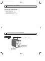
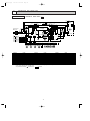
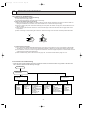
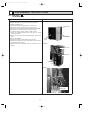
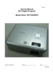
PART NAMES AND FUNCTIONS
OUTDOOR UNIT
Air inlet
MXZ-32SV- E1
(back and side)
Model indication
Air outlet
2
5/9/00 11:58 AM
3
Page 3
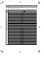
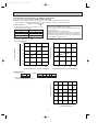
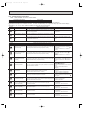
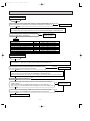
INDOOR / OUTDOOR CORRESPONDENCE TABLE
NOTE: MCFH-13NV, SEH-1.6AR is equivalent to class 12 (12000BTU).
SEH-2AR is equivalent to class 18 (18000BTU).
OUTDOOR UNIT
MXZ-32SV- E1
Combination of the connectable indoor units
OB254-1.qxp
07+07
07+09
07+12
07+18
09+09
09+12
09+18
12+12
12+18
18+18
07+07+07
07+07+09
07+07+12
07+07+18
07+09+09
07+09+12
07+09+18
07+12+12
07+12+18
07+18+18
09+09+09
09+09+12
09+09+18
09+12+12
09+12+18
09+18+18
12+12+12
12+12+18
07+07+07+07
07+07+07+09
07+07+07+12
07+07+07+18
07+07+09+09
07+07+09+12
07+07+09+18
07+07+12+12
07+07+12+18
07+09+09+09
07+09+09+12
07+09+09+18
07+09+12+12
09+09+09+09
09+09+09+12
09+09+09+18
09+09+12+12
❈There is no combination other than this table.
3
OB254-1.qxp
4
5/9/00 11:58 AM
Page 4
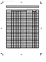
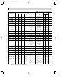
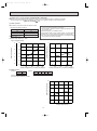
INDOOR UNITS COMBINATION
MXZ-32SV - E1
NOTE: Electrical data is for outdoor unit only.
Cooling capacity (kw)
Outdoor unit
power consumption
(kw)
Current
(A)
220V 240V
Power
factor
(%)
Indoor units
combination
Unit A
Unit B
Unit C
Unit D
Total
07
2.2
-
-
-
2.2
(0.9-2.7)
0.75
(0.26-0.93)
3.79
3.47
90
09
2.8
-
-
-
2.8
(0.9-3.2)
0.90
(0.26-1.04)
4.55
4.17
90
12
4.0
-
-
-
4.0
(0.9-4.5)
1.44
(0.26-1.70)
7.27
6.67
90
18
5.0
-
-
-
5.0
(0.9-5.4)
2.30
(0.26-2.98)
11.62
10.65
90
07+07
2.2
2.2
-
-
4.4
(1.8-5.4)
1.54
(0.58-1.96)
7.78
7.13
90
07+09
2.2
2.8
-
-
5.0
(1.8-5.8)
1.62
(0.58-2.05)
8.18
7.50
90
07+12
2.2
4.0
-
-
6.2
(1.8-6.6)
2.28
(0.58-2.51)
11.52
10.56
90
07+18
2.2
5.0
-
-
7.2
(1.8-7.7)
3.09
(0.58-3.65)
15.61 14.31
90
09+09
2.8
2.8
-
-
5.6
(1.8-6.2)
1.90
(0.58-2.18)
9.60
8.80
90
09+12
2.8
4.0
-
-
6.8
(1.8-7.3)
2.73
(0.58-3.22)
13.79 12.64
90
09+18
2.8
5.0
-
-
7.8
(1.8-8.5)
3.74
(0.58-4.56)
18.89 17.31
90
12+12
4.0
4.0
-
-
8.0
(1.8-8.8)
3.96
(0.58-4.90)
20.00 18.33
90
12+18
3.5
4.5
-
-
8.0
(1.8-8.8)
3.96
(0.58-4.90)
20.00 18.33
90
18+18
4.0
4.0
-
-
8.0
(1.8-8.8)
3.96
(0.58-4.90)
20.00 18.33
90
07+07+07
2.2
2.2
2.2
-
6.6
(2.4-8.1)
2.20
(0.70-3.65)
11.11
10.19
90
07+07+09
2.2
2.2
2.8
-
7.2
(2.4-8.6)
2.43
(0.70-4.11)
12.27
11.25
90
07+07+12
2.1
2.1
3.8
-
8.0
(2.4-9.0)
2.98
(0.70-4.27)
15.05 13.80
90
07+07+18
1.9
1.9
4.2
-
8.0
(2.4-9.0)
2.98
(0.70-4.27)
15.05 13.80
90
07+09+09
2.2
2.8
2.8
-
7.8
(2.4-8.9)
2.80
(0.70-4.23)
14.14 12.96
90
07+09+12
1.9
2.5
3.6
-
8.0
(2.4-9.0)
2.98
(0.70-4.27)
15.05 13.80
90
07+09+18
1.7
2.3
4.0
-
8.0
(2.4-9.0)
2.98
(0.70-4.27)
15.05 13.80
90
07+12+12
1.8
3.1
3.1
-
8.0
(2.4-9.0)
2.98
(0.70-4.27)
15.05 13.80
90
07+12+18
1.6
2.8
3.6
-
8.0
(2.4-9.0)
2.98
(0.70-4.27)
15.05 13.80
90
07+18+18
1.5
3.25
3.25
-
8.0
(2.4-9.0)
2.98
(0.70-4.27)
15.05 13.80
90
NOTE: MCFH-13NV, SEH-1.6AR is equivalent to class 12 (12000BTU).
SEH-2AR is equivalent to class 18 (18000BTU).
4
OB254-1.qxp
5/9/00 11:58 AM
Page 5
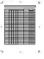
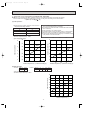
NOTE: Electrical data is for outdoor unit only.
Cooling capacity (kw)
Outdoor unit
power consumption
(kw)
Current
(A)
220V 240V
Power
factor
(%)
8.0
(2.4-9.0)
2.98
(0.70-4.27)
15.05 13.80
90
-
8.0
(2.4-9.0)
2.98
(0.70-4.27)
15.05 13.80
90
3.8
-
8.0
(2.4-9.0)
2.98
(0.70-4.27)
15.05 13.80
90
3.0
3.0
-
8.0
(2.4-9.0)
2.98
(0.70-4.27)
15.05 13.80
90
1.9
2.7
3.4
-
8.0
(2.4-9.0)
2.98
(0.70-4.27)
15.05 13.80
90
09+18+18
1.8
3.1
3.1
-
8.0
(2.4-9.0)
2.98
(0.70-4.27)
15.05 13.80
90
12+12+12
2.67
2.67
2.67
-
8.0
(2.4-9.0)
2.98
(0.70-4.27)
15.05 13.80
90
12+12+18
2.45
2.45
3.1
-
8.0
(2.4-9.0)
2.98
(0.70-4.27)
15.05 13.80
90
07+07+07+07
2.0
2.0
2.0
2.0
8.0
(2.8-9.0)
2.98
(0.80-4.27)
15.05 13.80
90
07+07+07+09
1.87
1.87
1.87
2.4
8.0
(2.8-9.0)
2.98
(0.80-4.27)
15.05 13.80
90
07+07+07+12
1.7
1.7
1.7
2.9
8.0
(2.8-9.0)
2.98
(0.80-4.27)
15.05 13.80
90
07+07+07+18
1.5
1.5
1.5
3.5
8.0
(2.8-9.0)
2.98
(0.80-4.27)
15.05 13.80
90
07+07+09+09
1.8
1.8
2.2
2.2
8.0
(2.8-9.0)
2.98
(0.80-4.27)
15.05 13.80
90
07+07+09+12
1.6
1.6
2.0
2.8
8.0
(2.8-9.0)
2.98
(0.80-4.27)
15.05 13.80
90
07+07+09+18
1.5
1.5
1.8
3.2
8.0
(2.8-9.0)
2.98
(0.80-4.27)
15.05 13.80
90
07+07+12+12
1.4
1.4
2.6
2.6
8.0
(2.8-9.0)
2.98
(0.80-4.27)
15.05 13.80
90
07+07+12+18
1.3
1.3
2.4
3.0
8.0
(2.8-9.0)
2.98
(0.80-4.27)
15.05 13.80
90
07+09+09+09
1.7
2.1
2.1
2.1
8.0
(2.8-9.0)
2.98
(0.80-4.27)
15.05 13.80
90
07+09+09+12
1.5
1.9
1.9
2.7
8.0
(2.8-9.0)
2.98
(0.80-4.27)
15.05 13.80
90
07+09+09+18
1.4
1.75
1.75
3.1
8.0
(2.8-9.0)
2.98
(0.80-4.27)
15.05 13.80
90
07+09+12+12
1.35
1.75
2.45
2.45
8.0
(2.8-9.0)
2.98
(0.80-4.27)
15.05 13.80
90
09+09+09+09
2.0
2.0
2.0
2.0
8.0
(2.8-9.0)
2.98
(0.80-4.27)
15.05 13.80
90
09+09+09+12
1.8
1.8
1.8
2.6
8.0
(2.8-9.0)
2.98
(0.80-4.27)
15.05 13.08
90
09+09+09+18
1.67
1.67
1.67
3.0
8.0
(2.8-9.0)
2.98
(0.80-4.27)
15.05 13.08
90
09+09+12+12
1.65
1.65
2.35
2.35
8.0
(2.8-9.0)
2.98
(0.80-4.27)
15.05 13.08
90
Indoor units
combination
Unit A
Unit B
Unit C
Unit D
Total
09+09+09
2.67
2.67
2.67
-
09+09+12
2.3
2.3
3.4
09+09+18
2.1
2.1
09+12+12
2.0
09+12+18
NOTE: MCFH-13NV, SEH-1.6AR is equivalent to class 12 (12000BTU).
SEH-2AR is equivalent to class 18 (18000BTU).
5
OB254-1.qxp
5/9/00 11:58 AM
Page 6
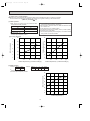
NOTE: Electrical data is for outdoor unit only.
Heating capacity (kw)
Outdoor unit
power consumption
(kw)
Current
(A)
220V 240V
Power
factor
(%)
Indoor units
combination
Unit A
Unit B
Unit C
Unit D
Total
07
3.2
-
-
-
3.2
(0.9-4.1)
1.13
(0.27-1.60)
5.71
5.23
90
09
4.0
-
-
-
4.0
(0.9-4.8)
1.32
(0.27-1.70)
6.67
6.11
90
12
6.0
-
-
-
6.0
(0.9-7.2)
1.91
(0.27-2.57)
9.65
8.84
90
18
7.1
-
-
-
7.1
(0.9-7.8)
2.30
(0.27-2.83)
11.62 10.65
90
07+07
3.2
3.2
-
-
6.4
(1.8-7.2)
1.93
(0.48-2.30)
9.75
8.94
90
07+09
3.2
4.0
-
-
7.2
(1.8-8.7)
2.05
(0.48-2.68)
10.35
9.49
90
07+12
3.2
5.4
-
-
8.6
(1.8-10.6)
2.55
(0.48-3.80)
12.88 11.81
90
07+18
2.8
6.2
-
-
9.0
(1.8-10.9)
2.68
(0.48-3.89)
13.54 12.41
90
09+09
4.0
4.0
-
-
8.0
(1.8-10.1)
2.35
(0.48-3.56)
11.87 10.88
90
09+12
3.5
5.3
-
-
8.8
(1.8-10.8)
2.62
(0.48-3.86)
13.23 12.13
90
09+18
3.35
5.95
-
-
9.3
(1.8-11.2)
2.78
(0.48-3.98)
14.04 12.87
90
12+12
4.65
4.65
-
-
9.3
(1.8-11.2)
2.78
(0.48-3.98)
14.04 12.87
90
12+18
4.3
5.0
-
-
9.3
(1.8-11.2)
2.78
(0.48-3.98)
14.04 12.87
90
18+18
4.65
4.65
-
-
9.3
(1.8-11.2)
2.78
(0.48-3.98)
14.04 12.87
90
07+07+07
2.87
2.87
2.87
-
8.6
(2.1-10.6)
2.42
(0.52-3.00)
12.22 11.20
90
07+07+09
2.75
2.75
3.5
-
9.0
(2.1-11.1)
2.50
(0.52-3.30)
12.63 11.57
90
07+07+12
2.4
2.4
4.5
-
9.3
(2.1-11.6)
2.78
(0.52-3.50)
14.04 12.87
90
07+07+18
2.2
2.2
4.9
-
9.3
(2.1-11.6)
2.78
(0.52-3.50)
14.04 12.87
90
07+09+09
2.7
3.3
3.3
-
9.3
(2.1-11.6)
2.78
(0.52-3.50)
14.04 12.87
90
07+09+12
2.25
2.8
4.25
-
9.3
(2.1-11.6)
2.78
(0.52-3.50)
14.04 12.87
90
07+09+18
2.1
2.6
4.6
-
9.3
(2.1-11.6)
2.78
(0.52-3.50)
14.04 12.87
90
07+12+12
2.0
3.65
3.65
-
9.3
(2.1-11.6)
2.78
(0.52-3.50)
14.04 12.87
90
07+12+18
1.85
3.4
4.05
-
9.3
(2.1-11.6)
2.78
(0.52-3.50)
14.04 12.87
90
07+18+18
1.7
3.8
3.8
-
9.3
(2.1-11.6)
2.78
(0.52-3.50)
14.04 12.87
90
NOTE: MCFH-13NV, SEH-1.6AR is equivalent to class 12 (12000BTU).
SEH-2AR is equivalent to class 18 (18000BTU).
6
OB254-1.qxp
5/9/00 11:59 AM
Page 7
NOTE: Electrical data is for outdoor unit only.
Heating capacity (kw)
Outdoor unit
power consumption
(kw)
Current
(A)
220V 240V
Power
factor
(%)
9.3
(2.1-11.6)
2.78
(0.52-3.50)
14.04 12.87
90
-
9.3
(2.1-11.6)
2.78
(0.52-3.50)
14.04 12.87
90
4.4
-
9.3
(2.1-11.6)
2.78
(0.52-3.50)
14.04 12.87
90
3.5
3.5
-
9.3
(2.1-11.6)
2.78
(0.52-3.50)
14.04 12.87
90
2.2
3.3
3.8
-
9.3
(2.1-11.6)
2.78
(0.52-3.50)
14.04 12.87
90
09+18+18
2.0
3.65
3.65
-
9.3
(2.1-11.6)
2.78
(0.52-3.50)
14.04 12.87
90
12+12+12
3.1
3.1
3.1
-
9.3
(2.1-11.6)
2.78
(0.52-3.50)
14.04 12.87
90
12+12+18
2.9
2.9
3.5
-
9.3
(2.1-11.6)
2.78
(0.52-3.50)
14.04 12.87
90
07+07+07+07
2.32
2.32
2.32
2.32
9.3
(2.8-11.6)
2.78
(0.60-3.50)
14.04 12.87
90
07+07+07+09
2.2
2.2
2.2
2.7
9.3
(2.8-11.6)
2.78
(0.60-3.50)
14.04 12.87
90
07+07+07+12
1.9
1.9
1.9
3.6
9.3
(2.8-11.6)
2.78
(0.60-3.50)
14.04 12.87
90
07+07+07+18
1.8
1.8
1.8
3.9
9.3
(2.8-11.6)
2.78
(0.60-3.50)
14.04 12.87
90
07+07+09+09
2.1
2.1
2.55
2.55
9.3
(2.8-11.6)
2.78
(0.60-3.50)
14.04 12.87
90
07+07+09+12
1.8
1.8
2.3
3.4
9.3
(2.8-11.6)
2.78
(0.60-3.50)
14.04 12.87
90
07+07+09+18
1.7
1.7
2.15
3.75
9.3
(2.8-11.6)
2.78
(0.60-3.50)
14.04 12.87
90
07+07+12+12
1.6
1.6
3.05
3.05
9.3
(2.8-11.6)
2.78
(0.60-3.50)
14.04 12.87
90
07+07+12+18
1.6
1.6
2.8
3.3
9.3
(2.8-11.6)
2.78
(0.60-3.50)
14.04 12.87
90
07+09+09+09
1.95
2.45
2.45
2.45
9.3
(2.8-11.6)
2.78
(0.60-3.50)
14.04 12.87
90
07+09+09+12
1.75
2.15
2.15
3.25
9.3
(2.8-11.6)
2.78
(0.60-3.50)
14.04 12.87
90
07+09+09+18
1.65
2.0
2.0
3.65
9.3
(2.8-11.6)
2.78
(0.60-3.50)
14.04 12.87
90
07+09+12+12
1.55
1.95
2.9
2.9
9.3
(2.8-11.6)
2.78
(0.60-3.50)
14.04 12.87
90
09+09+09+09
2.32
2.32
2.32
2.32
9.3
(2.8-11.6)
2.78
(0.60-3.50)
14.04 12.87
90
09+09+09+12
2.05
2.05
2.05
3.15
9.3
(2.8-11.6)
2.78
(0.60-3.50)
14.04 12.87
90
09+09+09+18
1.95
1.95
1.95
3.45
9.3
(2.8-11.6)
2.78
(0.60-3.50)
14.04 12.87
90
09+09+12+12
1.85
1.85
2.8
2.8
9.3
(2.8-11.6)
2.78
(0.60-3.50)
14.04 12.87
90
Indoor units
combination
Unit A
Unit B
Unit C
Unit D
Total
09+09+09
3.1
3.1
3.1
-
09+09+12
2.65
2.65
4.0
09+09+18
2.45
2.45
09+12+12
2.3
09+12+18
NOTE: MCFH-13NV, SEH-1.6AR is equivalent to class 12 (12000BTU).
SEH-2AR is equivalent to class 18 (18000BTU).
7
OB254-1.qxp
5
5/9/00 11:59 AM
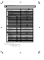
Page 8
SPECIFICATION
Outdoor model
Indoor units number
Indoor units total capacity (Connectable)
indoor units total capacity (Simultaneous operation)
Piping total length
Connecting pipe length
Height difference (Indoor ~ Outdoor)
Height difference (Indoor ~ Indoor)
Function
kW
Capacity
R/h
Dehumidification
K /h
Outdoor air flow
A
Power outlet
A
Running current
W
Power input
A(kW)
Auxiliary heater
W
Crankcase heater
%
Power factor
A
Starting current
A
Compressor motor current
A
Fan motor current
Coefficient of performance(C.O.P)
Special
remarks
Fan
motor
Compressor
Electrical
data
Capacity
System
Outdoor unit power supply
Model
Output
Winding
resistance(at20:)
Model
Winding
resistance(at20:)
Dimensions WOHOD
Weight
Sound level (Hi)
Fan speed (Hi)
Fan speed regulator
Refrigerant filling
capacity(R-22)
Refrigerating oil (Model)
Thermistor RT61
Thermistor RT62
Thermistor RT63
Thermistor RT65
Thermistor RT66,67
Thermistor RT68,69
2400-2640
25
14.04-12.87
15.05-13.80
2780(270~3500)
2980(260~4270)
—
—
90.0
15.05-13.80
13.44-12.27
15.71-14.35
0.6
3.35
2.68
THV-247FBA (ROTARY)
2100
U-V 0.61
V-W 0.61 W-U 0.61
RA6V60WHT-BLK 78.7 BLK-YLW 26.9
YLW-BLU 11.7 BLU-RED 83.6
900o900o320 (+35)
79
46-48
45-47
W
"
"
mm
kg
dB
rpm
630-675
3
kg
3.9
cc
k"
k"
k"
k"
k"
k"
870 (MS-56)
13.4 (at 100:)
10.0 (at 25:)
17.0 (at 50:)
10.0 (at 25:)
10.0 (at 25:)
10.0 (at 25:)
✽1 Electrical data is for only outdoor unit.
TEST CONDITIONS COOLING INDOOR
OUTDOOR
HEATING INDOOR
OUTDOOR
MXZ-32SV - E1
Single phase
220-240V,50Hz
2 to 4
Total model name 42
Total model name 42
Max. 60
Max. 25
10
10
Heating
Cooling
9.3 (0.9~11.6)
8.0 (0.9~9.0)
—
—
DB27.0°C WB19.0°C
DB35.0°C WB24.0°C
DB20.0°C
DB 7.0°C WB 6.0°C
8
5/9/00 11:59 AM
6
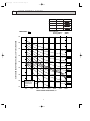
Page 9
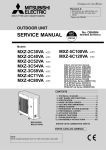
NOISE CRITERIA CURVES
NOTCH
SPL(dB(A))
COOL(220V)
45
COOL(240V)
47
HEAT(220V)
46
HEAT(240V)
48
Test conditions.
Cooling :DB35:
Heating :DB 7:
MXZ-32SV - E1
LINE
WB24:
WB 6:
90
OCTAVE BAND SOUND PRESSURE LEVEL, 0dB = 0.0002 MICRO BAR
OB254-1.qxp
80
70
NC-70
60
NC-60
50
NC-50
40
NC-40
30
NC-30
20
APPROXIMATE
TERESHOLD OF
HEARING FOR
CONTINUOUS
NOISE
NC-20
10
63
125
250
500
1000
2000
BAND CENTER FREQUENCIES, Hz
9
4000
8000
OB254-1.qxp
5/9/00 11:59 AM
7
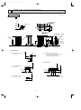
Page 10
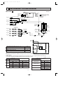
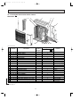
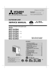
OUTLINES AND DIMENSIONS
Unit: mm
OUTDOOR UNIT
MXZ-32SV - E1
500
200
2-U-shape notched holes
(Base bolt M10)
Rubber cushion
27
Air in
(16)
Base bollt length
Less than
25
200
Veranda
Air in
(16)
40
Air out
387
355
Base
2-12 ✕ 36 Oval hole
(Base bolt M10)
10
Handle for
moving
320
35
[ 9.52 (flared) 3/8 (C , D unit)
[ 12.7 (flared) 1/2 (A , B unit)
900
Indoor and
outdoor
connect wiring
23✕45 hole
Air in
Air in
88
900
531.3
480.8
350.0
50
460
33
23
23
317
D unit connection
C unit connection
B unit connection
A unit connection
Liquid pipe
[ 6.35 (flared) 1/4
1.Installation space
More than
500
Note : Leave front and both sides
clearance fully.
More than
500
More than
350
More than
100
More than
350
More than
500
Note : Leave front, overhead and
both clearance fully.
2.Service space
More than
100
More than
100
Note : Obsacle on front and rear sid only.
The unit can be used by attaching an optional
outdoor outlet guide (MAC-855SG)
(but both sides and the top are opend.)
More than
200
Note : Leave front and overhead
clearance fully.
More than
100
More than
350
Service space
10
5/9/00 11:59 AM
8
Page 11
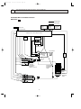
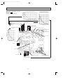
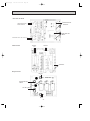
WIRING DIAGRAM
E1
X65
BRN
GRY
2 1
CN552
MODELS MXZ-32SV-
OUTDOOR UNIT
21S4
CN792
1 2 3456
LEV B
NAME
POWER FACTOR CAPACITOR
SMOOTHING CAPACITOR
OUTDOOR FAN CAPACITOR
CURRENT TRANSFORMER
DIODE MODULE
DIODE STACK
FUSE (1A)
FUSE (1A)
REACTOR
COMMON MODE CHOKE COIL
CN852
CN793
1 2 3456
7 65 43 2 1
CN515
TAB64
RED
WHT
ORN
X67
RELAY
P.C. BOARD
TAB65
CT62
TAB66
ELECTRONIC CONTROL P.C. BOARD
CN794
1 2 3456
LEV C
SYMBOL
LEV A~D
MC
MF61
R
RT61
RT62
RT63
RT65
RT66,67
RT68,69
LEV D
CN722
1 2 34
CN663
CN662
1 2
1 2 3456 78
63H1
CN661
1 2 3456 78
RT63
RT62
RT68
RT65 RT66
RT67
RT69
RT61
NAME
EXPANSION VALVE
COMPRESSOR
OUTDOOR FAN MOTOR (INNER FUSE)
RESISTOR
DISCHARGE TEMPERATURE THERMISTOR
DEFROST TEMPERATURE THERMISTOR
EVAPORATION TEMPERATURE THERMISTOR
FIN TEMPERATURE THERMISTOR
GUS PIPE TEMPERATURE THERMISTOR
GUS PIPE TEMPERATURE THERMISTOR
NOTE: 1. About the indoor side electric wiring refer to the indoor unit electric wiring diagram for servicing.
2.Use copper conductors only. (For field wiring)
3.Symboles below indicate. : Terminal block
: Connector
11
SYMBOL
SSR61
T801
TB2,3,4
X61,62,63
X64,65
X66,67
21S4
63H1
63H2
NAME
SOLENOID COIL RELAY
TRANSFORMER
TERMINAL BLOCK
FAN MOTOR RELAY
RELAY
RELAY
R.V. COIL
HIGH PRESSURE SWITCH
HIGH PRESSURE SWITCH
WHT
CN554
X66
ORN
W
I.P.M P.C. BOARD
MF61
BLK
BLK
CN851
MC
BLK
X61
X62
4
RED
RED
CN791
1 2 3456
LEV A
SYMBOL
C61
C62,63
C65
CT61,62
DS61
DS62
F801
F911
L
L61
RED
RED
BLU
BRN
6
1 2 3456
V
U
C65
CN913
1 2 34
RED
BRN
BLU
ORN
YLW
WHT
N
CN902
GRN
RED
BRN
BLU
ORN
YLW
WHT
1 2
1 2
BLU
YLW
1 2
N
CN901
RED
BRN
BLU
ORN
YLW
WHT
3
BLU
ORN
1 2
3
N
CN604 CN603 CN602 CN601
3
3
CN720
BLU
RED
2
T801
1 2 34567
CN705
TB3
N
X63
(1A)
1 2
INDOOR
UNIT (A)
INDOOR
UNIT (B)
INDOOR
UNIT (C)
INDOOR
UNIT (D)
LDB
F911
LDE
RED
BRN
BLU
ORN
YLW
WHT
BRN
CIRCUIT BRAKER
BLK
GRY
GRY
BLK
BLK
GRY
GRY
LD61
GRY
GRY
GRY
GRY
GRY
GRY
GRY
GRY
BLU
YLW
BLU
N
L61
RED
ORN
WHT
BLK
LD62
GRY
BLK
CN704
L
NOISE FILTER
P.C.BOARD
SSR61
LD64
X64
0 1
TB2
PE
CT
61
1 2 34
CN801
POWER SUPPLY
~/N 220-240V
50Hz
X64 4 6 BLK
LDB
LD63
TB4
GRN/YLW
YLW
TAB63
YLW
REDR BLK
BLK
RED
-
YLW
(1A)
-
WHT
CN551
C63
C62
+ RED +
L
K
F801 TAB62
A
43 21
CN501
-
CN514
-
2 1
CN553
WHT
BLK
ORN
WHT
DS62
DS61
C61
+ ORN +
RED
FROM INDOOR UNIT
CONNECTING 12V
OB254-1.qxp
63H2
OB254-1.qxp
9
5/9/00 11:59 AM
Page 12
REFRIGERANT SYSTEM DIAGRAM
MXZ-32SV - E1
Unit:mm
[16
Compressor
High pressure
switch 1
High pressure
switch 2
Oil
separator
Unit D gas pipe temperature thermistor
[9.52
Indoor unit
D
Unit C gas pipe temperature thermistor
Indoor unit
C
Indoor unit
B
Discharge
temperature
thermistor
Capillary tube
Refrigerant flow in cooling
Refrigerant flow in heating
Accumulator
[2.5✕ [0.6✕1000
Reversing valve coil
heating ON
cooling OFF
Ball valve with
service port
[9.52
Reversing valve
Unit B gas pipe temperature
thermistor
[12
[16
[16
Unit A gas pipe
temperature thermistor
[12
Indoor unit
A
Evaporation
temperature
thermistor
(RT67)
Outdoor
heat
exchanger
Capillary tube
[3.0✕[2.0✕ 200
Indoor unit
A
Strainer Capillary tube
[3.0✕[2.0✕ 200
Indoor unit
B
Indoor unit
C
Indoor unit
D
LEV
Strainer Capillary tube
[3.0✕[2.0✕ 200
LEV
Strainer Capillary tube
[3.0✕[2.0✕ 200
LEV
Strainer
LEV
Ball valve with
service port
[6
Capillary tube
[2.5✕[0.6✕ 750
Capillary tube
[4.0✕[2.4✕ 400
Defrost
thermistor
[6
[6
Distributor
Strainer
Distributor
[9.52
[6
Strainer
Indoor
units
a
b
Piping length each indoor unit (a, b, c, d)
25m
Total piping length (a+b+c+d)
60m
Height difference between units (H)
10m
Bending point for each unit
25
Total bending point
60
Outdoor
unit
H
H
c
H
d
❋It does not matter which unit is higher.
● Refrigerant pipe diameter is different according to indoor unit to be connected. When using extension pipes,refer to the
tables below.
● When diameter of refrigerant pipe is different from that of outdoor unit union, use optional Different-diameter pipe.
For further information on Different-diameter pipe,see page BACK COVER.
Unit : mm (inch)
Indoor unit
class
07/09
12(13)
18
Pipe diameter
Liquid
6.35(1/4)
Extension pipe diameter
Liquid
6.35(1/4)
Gas
9.52(3/8)
Gas
9.52(3/8)
Liquid
6.35(1/4)
Liquid
6.35(1/4)
Outdoor unit union diameter
For
Indoor unit A
Indoor unit B
Gas
12.7(1/2)
Gas
12.7(1/2)
Liquid
6.35(1/4)
Liquid
6.35(1/4)
Gas
15.88(5/8)
Gas
15.88(5/8)
Indoor unit C
Indoor unit D
12
Liquid
6.35(1/4)
Gas
12.7(1/2)
Liquid
6.35(1/4)
Gas
12.7(1/2)
Liquid
6.35(1/4)
Gas
9.52(3/8)
Liquid
6.35(1/4)
Gas
9.52(3/8)
OB254-1.qxp
5/9/00 11:59 AM
10
Page 13
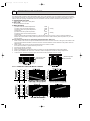
PERFORMANCE CURVES
The standard data contained in these specifications apply only to the operation of the air conditioner under normal conditions,
since operating conditions vary according to the areas where these units are installed. The following information has been provided to clarify the operating characteristics of the air conditioner under the conditions indicated by the performance curve.
(1) GUARANTEED VOLTAGE
Rated voltage : ±10% (198 ~ 264V),50Hz
(2) AIR FLOW
Air flow should be set at MAX.
(3) MAIN READINGS
}
(1) Indoor intake air wet-bulb temperature :
°CWB
(2) Indoor outlet air wet-bulb temperature :
°CWB
Cooling
(3) Outdoor intake air dry-bulb temperature :
°CDB
(4) Total input:
W
(5) Indoor intake air dry-bulb temperature :
°CDB
Heating
(6) Outdoor intake air wet-bulb temperature :
°CWB
(7) Total input :
W
Indoor air wet/dry-bulb temperature difference on the left side of the chart on page 14 and 15 shows the difference
between the indoor intake air wet/dry-bulb temperature and the indoor outlet air wet/dry-bulb temperature for your reference at service.
}
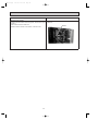
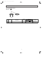
How to measure the indoor air wet-bulb/dry-bulb temperature difference
1.
2.
3.
4.
5.
6.
7.
Attach at least 2 sets of wet-and dry-bulb thermometers to the indoor air intake as shown in the figure, and at least 2 sets
of wet-and dry-bulb thermometers to the indoor air outlet. The thermometers must be attached to the position where air
speed is high.
Attach at least 2 sets of wet-and dry-bulb thermometers to the outdoor air intake.
Cover the thermometers to prevent direct rays of the sun.
Check that the air filter is cleaned.
Open windows and doors of room.
Press the EMERGENCY OPERATION switch once(twice) to start the EMERGENCY COOL(HEAT) MODE.
When system stabilizes after more than 15 minutes, measure temperature and take an average temperature.
10 minutes later, measure temperature again and check that the temperature does not change.
INDOOR UNIT
OUTDOOR UNIT
Wet-and dry-bulb
thermometers
10-1-1.CAPACITY AND THE INPUT CURVES
6.4
5.8 7.4
9.3
5.9
5.3 6.8
8.5
5.3
4.8 6.2
7.7
4.8
4.3 5.6
7.0
18 class
10.1
12 class
10.8
6.2 8.1
09 class
6.7 8.7
7.0
07 class
7.5
25.9
27.7 32.3
38.2
23.9
25.6 29.8
35.3
21.9
23.4 27.3
32.4
19.9
21.3 24.9
29.4
17.9
19.2 22.4
26.5
12.8 14.9
17.6
18 class
20.6
11.9
12 class
23.5
14.9 17.4
09 class
17.0 19.9
07 class
15.9
13.9
13
Wet-and dry-bulb
thermometers
OB254-1.qxp
5/9/00 11:59 AM
Page 14
10-3-.2.Capacity and input correction by inverter output frequency
(OUTDOOR UNIT:MXZ-32SV)
NOTE 1 : Inverter output frequency : COOL 58Hz,HEAT 40Hz
NOTE 2 : The dotted line on graphs connects the frequency range in normal operation shown by the full line and the frequency
in test run shown by the point.
1. 07-class unit in single operation
<HEAT>Total input
<HEAT>Capacity
<COOL>Total input
<COOL>Capacity
2.0
1.5
1.5
1.5
1.5
1.0
1.0
1.0
1.0
0.5
0.5
0.5
0.5
0
50
100
0
150 Hz
50
100
0
150 Hz
Frequency
Frequency
50
100
150 Hz
0
50
100
150 Hz
Frequency
Frequency
2. 09-class unit in single operation
<COOL>Total input
<COOL>Capacity
<HEAT>Capacity
2.0
1.5
<HEAT>Total input
1.5
1.5
1.0
1.0
0.5
0.5
1.5
1.0
1.0
0.5
0.5
0
50
100
0
150 Hz
50
100
150 Hz
0
Frequency
Frequency
50
100
150 Hz
0
50
100
150 Hz
Frequency
Frequency
3. 12-class unit in single operation
<COOL>Total input
<COOL>Capacity
<HEAT>Total input
<HEAT>Capacity
2.0
1.5
1.5
1.5
1.0
1.0
0.5
0.5
1.5
1.0
1.0
0.5
0.5
0
50
100
150 Hz
0
50
100
150 Hz
0
Frequency
Frequency
50
100
150 Hz
0
50
100
150 Hz
Frequency
Frequency
4. 18-class unit in single operation
<COOL>Total input
<COOL>Capacity
<HEAT>Capacity
2.0
1.5
<HEAT>Total input
1.5
1.5
1.0
1.0
0.5
0.5
1.5
1.0
1.0
0.5
0.5
0
50
100
Frequency
150 Hz
0
50
100
150 Hz
Frequency
0
50
100
Frequency
14
150 Hz
0
50
100
Frequency
150 Hz
OB254-1.qxp
5/9/00 11:59 AM
Page 15
10-3-4.Outdoor low pressure and outdoor unit current
1. 07-class unit in single operation (OUTDOOR UNIT : MXZ-32SV)
NOTE:The unit of pressure has been changed to MPa on the international system of units(SI unit system).
The converted score against the traditional unit system can be gotten according to the formula below.
f • G)
1(MPa • G) =10.2(kgf/f
(1) COOL operation
1Both indoor and outdoor units are under the same
temperature/humidity condition.
Dry-bulb temperature(°C) Relative humidity(%)
20
50
25
60
30
70
<How to work fixed-frequency operation>
1.Set emergency switch to COOL or HEAT.The switch is located on indoor unit.
2.Press emergency run ON/OFF button.
3.Compressor starts running at 58Hz (COOL) or 40Hz (HEAT).
4.Indoor fan runs at HI speed and continues for 30 minutes.
5.To cancel this operation,press emergency run ON/OFF button
or any button on remote controller.
2Air flow speed : HI
3Inverter output frequency : 58Hz
(kgf/F• Gauge)(MPa•Gauge)
0.8
8
0.7
Outdoor unit current (A)
7
5
Outdoor low pressure
24Hz
6
0.6
5
0.5
4
0.4
3
0.3
2
0.2
4
24Hz
3
2
1
0
20
25
30 32 (:)
(%)
50
60
70
Ambient temperature(:)/ Ambient humidity(%)
18
18
20
50
25
60
30
70
32
(:)
(%)
Ambient temperature(:)/ Ambient humidity(%)
(2) HEAT operation
① Indoor DB(°C)
20.0
Outdoor DB(°C)
2
7
15
20.0
WB(°C)
14.5
WB(°C)
1
6
12
14.5
➁ Set air flow to Hi speed.
➂ Inverter output frequency is 40Hz.
Outdoor unit current (A)
8
7
36Hz
6
5
4
3
2
2
5
10
15
20
Ambient temperature(:)
15
25
OB254-1.qxp
5/9/00 11:59 AM
Page 16
2. 09-class unit in single operation (OUTDOOR UNIT : MXZ-32SV)
NOTE:The unit of pressure has been changed to MPa on the international system of units(SI unit system).
The converted score against the traditional unit system can be gotten according to the formula below.
f • G)
1(MPa • G) =10.2(kgf/f
(1) COOL operation
1Both indoor and outdoor units are under the same
temperature/humidity condition.
Dry-bulb temperature(°C)
Relative humidity(%)
20
50
25
60
30
70
<How to work fixed-frequency operation>
1.Set emergency switch to COOL or HEAT.The switch is located on indoor unit.
2.Press emergency run ON/OFF button.
3.Compressor starts running at 58Hz (COOL) or 40Hz (HEAT).
4.Indoor fan runs at HI speed and continues for 30 minutes.
5.To cancel this operation,press emergency run ON/OFF button
or any button on remote controller.
2Air flow speed : HI
3Inverter output frequency : 58Hz
(kgf/F• Gauge)(MPa•Gauge)
0.8
8
0.7
Outdoor unit current (A)
Outdoor low pressure
7
6
31Hz
6
5
0.6
0.5
4
0.4
3
0.3
2
0.2
5
4
31Hz
3
2
18
20
50
25
60
1
30 32 (:)
70
(%)
Ambient temperature(:)/ Ambient humidity(%)
20
25
30 32
(:)
(%)
50
60
70
Ambient temperature(:)/ Ambient humidity(%)
(2) HEAT operation
① Indoor DB(°C)
20.0
Outdoor DB(°C)
2
7
15
20.0
WB(°C)
14.5
WB(°C)
1
6
12
14.5
18
➁ Set air flow to Hi speed.
➂ Inverter output frequency is 40Hz.
Outdoor unit current (A)
10
9
8
48Hz
7
6
5
4
2
5
10
15
20
Ambient temperature(:)
16
25
OB254-1.qxp
5/9/00 11:59 AM
Page 17
3. 12(13)-class unit in single operation (OUTDOOR UNIT : MXZ-32SV)
NOTE:The unit of pressure has been changed to MPa on the international system of units(SI unit system).
The converted score against the traditional unit system can be gotten according to the formula below.
f • G)
1(MPa • G) =10.2(kgf/f
(1) COOL operation
1Both indoor and outdoor units are under the same
temperature/humidity condition.
Dry-bulb temperature(°C)
Relative humidity(%)
20
50
25
60
30
70
<How to work fixed-frequency operation>
1.Set emergency switch to COOL or HEAT.The switch is located on indoor unit.
2.Press emergency run ON/OFF button.
3.Compressor starts running at 58Hz (COOL) or 40Hz (HEAT).
4.Indoor fan runs at HI speed and continues for 30 minutes.
5.To cancel this operation,press emergency run ON/OFF button
or any button on remote controller.
2Air flow speed : HI
3Inverter output frequency : 58Hz
7
0.7
6
0.6
9
8
Outdoor unit current (A)
Outdoor low pressure
(kgf/F• Gauge) (MPa•Gauge)
0.8
8
46Hz
5
0.5
4
0.4
3
0.3
2
0.2
7
46Hz
6
5
4
18
20
50
25
60
3
30 32 (:)
70
(%)
Ambient temperature(:)/ Ambient humidity(%)
20.0
Outdoor DB(°C)
WB(°C) 14.5
➁ Set air flow to Hi speed.
➂ Inverter output frequency is 40Hz.
WB(°C)
20
25
30 32
(:)
(%)
50
60
70
Ambient temperature(:)/ Ambient humidity(%)
2
7
15
20.0
1
6
12
14.5
15
14
Outdoor unit current (A)
(2) HEAT operation
① Indoor DB(°C)
18
13
65Hz
12
11
10
9
8
7
2
5
10
15
20
Ambient temperature(:)
17
25
OB254-1.qxp
5/9/00 11:59 AM
Page 18
4. 18-class unit in single operation
NOTE:The unit of pressure has been changed to MPa on the international system of units(SI unit system).
The converted score against the traditional unit system can be gotten according to the formula below.
f • G)
1(MPa • G) =10.2(kgf/f
(1) COOL operation
① Both indoor and outdoor units are under the same
temperature/humidity condition.
Dry-bulb temperature(°C)
Relative humidity(%)
20
50
25
60
30
➁ Air flow speed : HI
➂ Inverter output frequency : 58Hz
70
<How to work fixed-frequency operation>
1.Set emergency switch to COOL or HEAT.The switch is located on indoor unit.
2.Press emergency run ON/OFF button.
3.Compressor starts running at 58Hz (COOL) or 40Hz (HEAT).
4.Indoor fan runs at HI speed.
5.To cancel this operation,press emergency run ON/OFF button
or any button on remote controller.
7
0.6
6
0.5
5
0.4
4
0.3
3
0.2
2
0.1
11
10
Outdoor unit current (A)
Outdoor low pressure
(kgf/F• Gauge) (MPa•Gauge)
0.7
8
70Hz
9
70Hz
8
7
6
18
20
50
25
60
5
30 32 (:)
70
(%)
Ambient temperature(:)/ Ambient humidity(%)
20.0
Outdoor DB(°C)
WB(°C) 14.5
➁ Set air flow to Hi speed.
➂ Inverter output frequency is 58Hz.
WB(°C)
20
25
30 32
(:)
(%)
50
60
70
Ambient temperature(:)/ Ambient humidity(%)
2
7
15
20.0
1
6
12
14.5
15
14
Outdoor unit current (A)
(2) HEAT operation
① Indoor DB(°C)
18
76Hz
13
12
11
10
9
8
2
5
10
15
20
Ambient temperature(:)
18
25
OB254-1.qxp
5/9/00 11:59 AM
11
Page 19
MICROPROCESSOR CONTROL
INVERTER MULTI SYSTEM CONTROL
MXZ-32SV - E1
Output signal
Input signal
Compressor
power
factor
Indoor unit
microprocessor
Compressor
primary
current
Compressor
secondary
current
Outdoor unit control microprocessor
Drive
circuit
SSR61
Transistor
module
Fin temperature
thermistor RT65
Accumulator
Comp.
H.P.S 63H2
Discharge
temperature
thermistor
RT61
H.P.S 63H1
Indoor Unit
D
Indoor Unit
C
Indoor Unit
B
Indoor Unit
A
x 61
x 62
x 63
R. V. coil
21S4
Gas pipe
temperature
thermistor
RT66, 67, 68, 69
Evaporation
temperature
thermistor
RT63
Outdoor
fan motor
MF61
Indoor Unit
A
Indoor Unit
B
Indoor Unit
C
Indoor Unit
D
Defrost
thermistor
RT62
LEV1
LEV2
LEV3
LEV4
19
OB254-1.qxp
5/9/00 11:59 AM
Page 20
11-1.LEV control
Linear expansion valve (LEV) is controlled by "Thermostat ON" commands given from each unit.
Indoor unit status
Stop of all indoor unit
When outdoor unit is operating,
some indoor unit stops and
some operates.
LEV opening
Opening before stop ➝ 500 pulse in 15 minutes
COOL : 5 pulse (full closed)
HEAT : 59 pulse (slightly opened)
When the outdoor unit operation (When the other indoor unit operate): 5 pulse.
When outdoor unit stops. (When the other indoor unit stops or thermo off):
Maintain LEV opening before stop ➝ 500 pulse in 15 minutes
Thermostat OFF in
COOL or DRY mode
• LEV opening for each indoor unit is determined by adding adjustment in accordance
with the number of operating unit and the capacity class to standard opening, based
on the operation frequency:
Ex.) Opening 130 pulse in standard opening 1 ➝ Minimum 80 pulse, Maximum 205
pulse. (Capacity code 4 at 1 unit operation) (Capacity code 1 at 4 unit operation)
• After starting operation, adjustment in accordance with intake super heat, discharge
temperature is included in standard opening. w1
Note: LEV opening in each frequency at DRY operation and COOL operation is the
same. However, velocity and compressor operation frequency controls are
different. See 11-2 Operational frequency range
(As far as the indoor unit velocity control goes, refer to DRY operation in
MICROPROCESSOR CONTROL in the indoor unit service manual.)
Thermostat ON in
COOL or DRY mode
• When the outdoor unit operates. (When the other indoor unit operates): 59 pulse
Thermostat OFF in HEAT mode • When the outdoor unit stops. (When the other indoor unit stops or thermo off):
Maintain LEV opening before stop ➝ 500 pulse in 15 minutes.
• LEV opening for each indoor unit is determined by adding adjustment in accordance
with the number of operating unit and the capacity class to standard opening, based
on the operation frequency:
Ex.) Opening 120 pulse in standard opening 1 ➝ Minimum 70 pulse, Maximum 165
pulse. (Capacity code 4 at 1 unit operation) (Capacity code 1 at 4 unit operation)
• After starting operation, opening becomes the one that adjustment in accordance
with discharge temperature was added to basic opening. w1
Thermostat ON in HEAT mode
w1 LEV opening when the outdoor unit operating: Upper limit 500, Lower limit 59
Determination of LEV standard opening in each indoor unit
• The standard opening is on the straight line, which connects an each standard point in the section where divided
into seven according to the operation frequency of compressor as shown in the figure below.
(LEV opening is controlled in proportion to the operation frequency.)
Note: Opening is adjusted at the standard opening according to the indoor unit conditions.
However, inclination of standard opening in each point of opening does not change with the original curve.
• Add opening provided in Difference in Capacity in the table below to the standard opening from 1 to 8,
when capacity of the indoor unit is excluding code 1.
• Add opening provided in Difference in Operation number in the table below to determined LEV opening for
each indoor unit, when 2, 3 or 4 indoor units are operated at the same time.
Note: Even when the adjusted standard opening exceeds the driving range from 59 to 500 pulse, actual
driving output opening is in a range from 59 to 500 pulse.
< Calculation example of LEV opening >
Cool operation: Compressor frequency 70Hz: 2 unit ON: 18class
(170-150)p(80-60)o(70-60)+150+75-30=205 pulse
Standard opening
LEV opening (Pulse)
1
2
3
4
5
6
7
8
220
210
200
190
180
170
160
150
140
130
120
COOL
HEAT
7
20
40
60
80
100
120
Operation frequency of compressor (Hz) : F
20
140
OB254-1.qxp
5/9/00 11:59 AM
Page 21
Standard opening
COOL
HEAT
1
130
120
2
130
130
3
130
140
4
150
155
Capacity code
Indoor unit
1
07
2
09
3
12
4
18
5
170
170
6
180
185
7
180
200
Difference in
capacity
8 Code2 Code3 Code4
190
25
50
75
215
15
30
45
Difference in
operation number
2
3
4
-30
-40
-50
-10
-40
-50
<Correction>
COOL
DRY
HEAT
•
•
-
1 Suction super heat
(MIN gas pipe temperature thermistor - Evaporation temperature thermistor)
2 Each correction w 1
• (Each gas pipe temperature thermistor - Evaporation temperature thermistor)
• (Main pipe temperature thermistor - sub pipe temperature thermistor)
•
3 Discharge temperature
w2
•
w2
•
w 1 Perform this, when number of operation units is 2units or more
w 2 When the correction opening of suction super heat is 0, correct the LEV opening by dischaege temperature.
(1) LEV opening correction by suction super heat (COOL, DRY)
(Suction super heat) = (Minimum gas pipe temperature) - (Evaporation temperature)
When COOL and DRY , correct the LEV openings corrected from the table below
Suction superheat (S.H.)
more than 12
10 to12
8 to 10
6 to 8
6 or less
LEV opening
correction (pulse)
6
4
3
2
0
(2) Separate correction (COOL,DRY)
(When number of operation unit is 2 units or more)
(a) Correction by the separate super heat
Correct the LEV separately by temperature difference between each gas pipe temperature thermistor and evaporator
temperature thermistor.
1 Calculate each super heat of the unit from the expression below;
(Super heat) = (Gas pipe temperature thermistor) - (Evaporation temperature thermistor)
2 Select a minimum super heat from among them.
3 Correct an each LEV is corrected opening is corrected by difference between each super heat and minimum super
heat.
Difference of
superheat
more than 9
6 to9
3to 6
6 or less
LEV opening
correction (pulse)
8
6
2
0
21
OB254-1.qxp
5/9/00 11:59 AM
Page 22
(3) LEV opening correction by discharge temperature
When LEV correction output is 0 pulse by the suction super heat at cool or dry operation, or dry operating, correct LEV is corrected according to the following table.
The target discharge temperature is determined according to frequency zone and number of operation unit of the
compressor.
COOL, DRY
HEAT
Operation frequency
Number of operating unit.
Number of operating unit.
of compressor
Triple Quadruple
Double
Triple Quadruple Single
Double
Single
47
48
49
55
64
62
60
51
Minimum ~ 20
50
51
52
58
68
66
64
57
21 ~ 30
53
54
55
63
75
73
68
65
31 ~ 40
56
57
58
70
81
79
72
67
41 ~ 55
61
62
63
80
88
86
77
70
56 ~ 70
67
68
69
85
90
90
83
72
71 ~ 90
72
73
74
85
90
90
84
74
91 ~ maximum
Correct the LEV opening according to difference between the target discharge temperature and discharge temperature.
LEV opening
correction (pulse)
Discharge temperature (;)
more than Target discharge temperature+11
Target discharge temperature+11 to Target discharge temperature+8
Target discharge temperature+8 to Target discharge temperature+5
Target discharge temperature+5 to Target discharge temperature+2
Target discharge temperature+2 to Target discharge temperature-2
Target discharge temperature-2 to Target discharge temperature-5
Target discharge temperature-5 to Target discharge temperature-8
Target discharge temperature-8 to Target discharge temperature-11
Target discharge temperature-11 or less
COOL
10
4
2
1
0
-1
-2
-5
-8
HEAT
7
6
3
2
0
-1
-1
-3
-7
11-2.Operational frequency range
Number of capacity
DRY
COOL
operating cord
Min. Max. Rated
unit
1
40
24
2
52
33
25
18
1
3
68
46
4
85
82
2
80
70
3
4
105
80
5
20
40
2
6
7
110
90
8
3
4
5
6
30
120
93
58
3
7
8
9
4
5
6
7
40
120 101
58
4
8
9
10
Min.
18
20
30
40
HEAT
Max. Defrost Rated
62
62
36
70
70
49
80
80
65
86
86
80
90
95
80
90
100
88
110
100
100
120
100
108
120
22
100
108
Note: When the fan speed of indoor unit is total
Lo notch, restrict the maximum frequency is
restricted in 6/7 of the rated frequency.
DRY COOL
Maximum frequency
1
1
8/10 of maximum frequency
2
2
1
2
9/10 of maximum frequency
1
3
2
1
7/10 of maximum frequency
3
1
OB254-1.qxp
5/9/00 11:59 AM
Page 23
11-3.Heat defrosting control
(1) Conditions to enter defrosting mode
1. When temperature of defrosting thermistor is -3; or less.
2.When specified non-defrosting time, is counted in the control p.c.board is satisfied.
(Total time of compressor operating)
Going to defrosting mode at both condition of 1 and 2.
(2) Defrosting operation
1. Compressor stops for 50 seconds, Indoor fan is off, Defrosting lamp lights
2.4-way valve reverses flow, Compressor operates by the frequency in heat defrosting control.
3. After compressor stops for 35 seconds, 4-way valve reverses flow, then defrosting finishes.
(3) Conditions to finish defrosting mode
1. When the defrosting thermistor temperature is 8; or more.
2. When it has spent 10 minutes for defrosting.
Defrosting finishes at condition of 1 or 2.
11-4.High or low pressure protection
(1) High pressure protection control on heat mode
Temperature of the main pipe temp. thermistor in the indoor unit controls the operation frequency.
When temperature of the main pipe temp. thermistor is approx. 49;, the operation frequency is set at the current level.
When temperature of the main pipe temp. thermistor is approx. 52; the protection control decreases the frequency at the
speed of 3Hz a minutes.
When temperature of the main pipe temp. thermistor is approx. 57; the protection decreases the frequency at the speed of
4Hz a minute and changes the outdoor fan to Low.
Note: Temperature of the pipe temp. thermistor is different depending on the indoor unit.
Temperature of the pipe temp. thermistor is 45; or less, the protection control is Released.
(2) High pressure protection control by high pressure switch (H.P.S)
High-pressure switch controls the operation frequency and outdoor fan motor.
<Control status>
When high-pressure switch is ON.
(When discharge pipe pressure is 2.75 MPa or more.)
<Control details>
(a) When cooling or drying
The protection control decreases the compressor frequency at the speed of 10Hz a minute.
(The compressor operates continuously in min. frequency according to a command to decrease more than the min. level.)
(b) When heating
The protection control decreases the compressor frequency at the speed of 10Hz a minute.
The protection control changes the outdoor fan to Low.
<Release status>
When high-pressure switch is OFF. (When discharge pipe pressure is 2.35 MPa or more.)
Or, the compressor stops.
11-5.Discharge temperature protection control
This protection controls the compressor ON/OFF and operation frequency according to temperature of the discharge temp.
thermistor.
(1) Compressor ON/OFF
When temperature of the discharge temp. thermistor exceeds 116;, the control stops the compressor.
When temperature of the discharge temp. thermistor is 80; or less, the controls starts the compressor.
(2) Compressor operation frequency
When temperature of the discharge temp. thermistor is expected to be higher than 116;, the control decreases 12Hz from the
current frequency.
When temperature of the discharge temp. thermistor is expected to be higher than 111; and less than 116;, the control
decreases 6Hz from the current frequency.
When temperature of the discharge temp. thermistor is expected to be higher than 104; and less than 111;, the control is set
at the current frequency.
23
OB254-1.qxp
5/9/00 11:59 AM
Page 24
11-6.Refrigerant recovery control on heating
<Control status>
The control performs when the following status are satisfied everything;
• When there is 1 unit or more not operating indoor unit on heat operation. (Excluding thermo OFF)
• When discharge temperature becomes 107; or more.
• When it passed 60 minutes or more since the operation has started or the last refrigerant recovery has controlled.
<Control details>
LEV opening, which adjusts to not operating indoor unit, is considered to be 80 pulse.
<Control finish status>
The control finishes either as follows. However, the LEV opening is considered to be 59 pulse.
• When it passed 60 seconds since the control has started.
• When the discharge temperature is 90; or less.
11-7.Outdoor fan control
Fan speed is switched according to a number of operating indoor unit and the compressor frequency.
Fan speed
Down
Hi
Up
Low
Min.
Compressor frequency
Max.
<Relation between compressor frequency and fan speed.>
Mode
COOL
HEAT
Up
Single
55 Hz
Indoor unit operation
Double
Triple
50 Hz
50Hz
Down
45 Hz
45 Hz
45 Hz
45 Hz
Up
60 Hz
45 Hz
40 Hz
40 Hz
Down
50 Hz
40 Hz
35 Hz
35 Hz
Fan speed
Quadruple
50 Hz
Note
• When operation, fan speed of Hi/ Low mode changes to VHi/ Hi mode by promoting those fan speeds respectively by
1 step after defrosting is operated. This control is cleared, when the compressor off.
• When overheat protection of P.C. board temperature or fin temperature operates, the outdoor fan speed is fixed to VHi
mode regardless of compressor frequency. Also, when the overheat protection is cleared, the fan speed is
back to normal
• When the indoor coil thermistor is 57; or more on HEAT operation, fan speed is fixed to Low notch .
Or, the indoor coil thermistor is 45; or less on HEAT operation, fan speed is back to normal.
11-8.Relation between main sensor and actuator
Relation between main sensor and actuator.
Sensor
Purpose
Compressor
Actuator
Outdoor
Reversing
LEV
fan motor
valve
Discharge temperature
Protection
thermistor
Indoor pipe temperature Defrosting
thermistor
Protection
Defrost thermistor
Defrosting
Evaporation temperature
Control
thermistor
Gas pipe temperature
Control
thermistor
High pressure
Protection
switch
Fin temperature
Protection
thermistor
Capacity code
Control
24
OB254-1.qxp
5/9/00 11:59 AM
12
Page 25
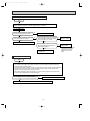
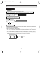
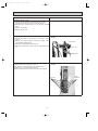
TROUBLESHOOTING
12-1. Cautions on troubleshooting
1. Before troubleshooting, check the following:
1) Check the power supply voltage.
2) Check the indoor/outdoor connecting wire for mis-wiring.
2. Take care the following during servicing.
1) Before servicing the air conditioner, be sure to first turn off the remote controller to stop the unit, and then after confirming the horizontal vane is closed, turn off the breaker and / or disconnect the power plug.
2) Be sure to unplug the power cord before removing the front panel, the cabinet, the top panel, and the electronic control P.C. board.
3) When removing the electronic control P.C. board, hold the edge of the board with care NOT to apply stress on the
components.
4) When connecting or disconnecting the connectors, hold the housing of the connector. DO NOT pull the lead wires.
Housing point
Lead wiring
3. Troubleshooting procedure
1) First, check if the OPERATION INDICATOR lamp on the indoor unit is flashing on and off to indicate an abnormality.
To make sure, check how many times the abnormality indication is flashing on and off before starting service work.
2) If the electronic control P.C. board is supposed to be defective, check the copper foil pattern for disconnection and the
components for bursting and discoloration.
3) When troubleshooting, refer to the flow chart on page 123, 124 and the check table on page 125~127.
12-2. Instruction of troubleshooting
• Check the indoor unit with referring to the indoor unit service manual, and confirm that there is any problem in the indoor unit.
Then, check the outdoor unit with referring to this page.
Operation start
Check the outdoor unit
LED indicator
Display other than "00"
"00"
OFF
A Check of power supply
See page 29.
• Indoor unit
serial signal
error
B Check of
serial signa
See page 29.
• Cool or HEAT
opereation only
C Check of
R.V.coil
See page 30.
Refer to indicator list
See page 26, 27.
• When cooling, heat
exchanger of
non-operating indoor
unit frosts.
•When heating, non
operating indoor unit
gets warm.
D Check of LEV
See page 31.
• When cooling,
dew drops in the
non-operating
indoor unit
Check of mispiping.
25
• When heating,
room doed not get
warm.
E Check of
inverter,compressor
See page 31.
Check mis-piping
Shortage of capacity
• When cooling,
room does not
cool.
E Check of
inverter,
compressor
See page 31.
OB254-1.qxp
5/9/00 2:50 PM
Page 26
12-3. Troubleshooting check table
Note . LED indicates "00" in the normal status.
7-segment LED display
Error mode
00
Normal
If there is defect in the following parts(electronic control P.C. board, relay P.C. board, high pressure
switches(63H1,63H2),indoor
/outdoor fan motor , or indoor coil thermistor), the compressor may stop even with the display
❈
remained at “ 00 “.In any case, reset the breaker and check the above-stated parts.
Symptom
Display
a4
Outdoor unit does not operate.
Detecting method
Detecting method
Check points
(A4)
When the compressor operation has been interrupted by overcurrent
Outdoor power system abnor• Inverter output
protection continuously three times within 1 minute after start-up, the
mality
• Compressor
compressor stops operation.
a3
Outdoor electronic control P.C. When the nonvolatile memory data cannot be read properly on the out• Outdoor electronic control P.C. board
board abnormality
door controller board
(A3)
p1
(P1)
Indoor unit and LEV abnormality
Symptom
Display
e9
(E9)
e6
(E6)
f8
(F8)
a8
Outdoor unit stops and restarts every 3 minutes.
Detecting method
(d6)
Detecting method
Check points
• Check the characteristic of the evaporation temperature thermistor. Refer to F
Evaporation temperature ther- The compressor stops when a short or open circuit occurs in the evapon page 32.
mistor abnormality
oration temperature thermistor during compressor running.
• Check the contact of P. C. board connectors.
Discharge temperature thermistor abnormality
• Check the characteristic of the discharge
temperature thermistor. Refer to F on
The compressor stops when a short or open circuit occurs in the dispage 32.
charge temperature thermistor during compressor running.
• Check the contact of P. C. board connectors.
Fin temperature thermistor
abnormality
• Check the characteristic of the fin temperThe compressor stops when a short or open circuit occurs in the fin temature thermistor. Refer to F on page 32.
perature thermistor during compressor running.
• Check the contact of P.C. board connectors.
Overcurrent protection
• Check the inverter and compressor.
Refer to E on page 31.
• Check the amount of gas.
When over current is applied to the power module, the compressor
• Check the indoor/outdoor air flow for short
stops and restarts in 3 minutes.
cycle.
• Check the indoor unit air filter for
clogging.
Discharge temperature overheat protection
When the discharge temperature thermistor detects 116˚C or above, the • Check the amount of gas and the refrigercompressor stops and restarts operation in 3 minutes.
ant cycle.
• Check the outdoor unit air passage.
(Protection will be released at 100; or below.)
(A8)
d6
When the drain abnormality is detected in the indoor unit and the indoor • Check the abnormality indication on the
main coil temperature is too low, or when any abnormality is detected in
indoor unit.
the components of indoor unit
• LEV
(d4)
• Check the outdoor unit air passage.
Fin temperature overheat pro- When the fin temperature thermistor detects 89˚C or above, the com- • Check the power module.
tection
pressor stops and restarts operation in 3 minutes.
• Check the outdoor fan motor. Refer to G
on page 32.
d7
High pressure protection
d4
(d7)
f5
(F5)
f6
(F6)
f7
(F7)
p9
(P9)
• Amount of gas
When the compressor starts, primary current or output voltage stops the
• Outdoor unit air passage.
compressor and restarts in 3 minutes.
• Check the ball valve.
Room-A gas pipe temperature When a short or open circuit occurs in the Room-A gas pipe
thermistor abnormality
temperature thermistor.
• Room A gas pipe temperature thermistor
characteristic.
• Contact of P.C. board connectors.
Room-B gas pipe temperature When a short or open circuit occurs in the Room-B gas pipe
thermistor abnormality
temperature thermistor.
• Room B gas pipe temperature thermistor
characteristic.
• Contact of P.C. board connectors.
Room-C gas pipe temperature When a short or open circuit occurs in the Room-C gas pipe
thermistor abnormality
temperature thermistor.
• Room C gas pipe temperature thermistor
characteristic.
• Contact of P.C. board connectors.
Room-D gas pipe temperature When a short or open circuit occurs in the Room-D gas pipe
thermistor abnormality
temperature thermistor.
• Room D gas pipe temperature thermistor
characteristic.
• Contact of P.C. board connectors.
26
OB254-1.qxp
5/9/00 2:50 PM
Page 27
Symptom
Display
Outdoor unit operates. (The compressor operates at reduced frequency.)
Detecting method
Detecting method
d8
(d8)
Frequency drop by current
protection
When the outdoor unit input current exceeds 22.5 A, the compressor
operates at reduced frequency.
d9
Frequency drop by overload
protection
Check points
(d7)
Frequency drop by defrosting
in cooling
When the compressor load exceeds the specified value, the compresThese symptoms do not mean any
sor operates at reduced frequency.
abnormality of the product, but check the
When indoor pipe temperature exceeds 55˚C during heating, the com- following points.
pressor operates at reduced frequency.
• Air filter clogging.
• Amount of gas.
When the indoor pipe temperature falls to 6˚C or below during cooling, • Short cycle of indoor/outdoor air flow.
the compressor operates at reduced frequency.
d6
Frequency drop by discharge
temperature protection
When the discharge temperature exceeds 110˚C, the compressor operates at reduced frequency.
Frequency drop by high pressure switch protection
When the high pressure exceeds 2.75MPa (28 kgf/cm2-G), the com• Amount of gas.
pressor operates at reduced frequency. In addition, the fan speed
• Outdoor unit air passage.
changes.
Low discharge temperature
protection
Check the amount of gas.
When the state with low discharge temperature of which 50˚C in COOL
• Replace the outdoor controller board.
and 48.4 or less in HEAT for 20 minutes, the compressor operates con• Check the contact of LEV board connectinuously.
tors.
(d9)
d7
(d6)
d3
(d3)
d1
(d1)
Frequency drop by high pressure protection
Symptom
Display
e7
(E7)
h4
(h4)
Outdoor unit operates.
Detecting method
Detecting method
Check points
When a short or open circuit occurs in the defrost thermistor during
Defrost thermistor abnormality heating
* In this case, the compressor continues to operate.
• Defrost thermistor characteristic.
• Contact of P. C. board connectors.
Power factor detection abnormality
• Compressor wiring.
When the compressor power factor cannot be detected
* In this case, the compressor keeps running.
27
OB254-1.qxp
5/10/00 3:28 PM
Page 28
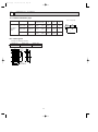
12-4. Trouble criterion of main parts
Part name
Defrost thermistor
Evaporation / Gas pipe
temperature thermistor
Discharge temperature
thermistor
Compressor
W
V
WHT
Measure the resistance using a tester.
(Part temperature -10°C ~ 40°C)
Normal
5kΩ ~ 55kΩ
abnormal
Opened or short-circuited
Measure the resistance using a tester, after warming up the thermistor by holding by hand.
(Part temperature : 20°C ~40°C)
Normal
100kΩ ~ 250kΩ
abnormal
Opened or short-circuited
Measure the resistance between terminals using a tester.
(Winding temperature : -10°C ~ 40°C)
RED
U
BLK
Outdoor fan motor
WHT
P
Check method and criterion
ORN
RED
BLU
YLW
BLK
Normal
1Each phase 0.53Ω ~ 0.66Ω
abnormal
Opened or short-circuited
Measure the resistance between lead wires using a tester.
(Part temperature : -10°C ~ 40°C)
Normal
69.0Ω
23.0Ω
10.0Ω
73.0Ω
WHT - BLK
BLK - YLW
YLW - BLU
RED - BLK
abnormal
~
~
~
~
86.0Ω
30.0Ω
13.0Ω
91.0Ω
Opened or
short-circuited
(Not including
WHT - ORN)
Measure the resistance using a tester. (Part temperature -10°C ~ 40°C)
R. V. coil
Normal
1640Ω ~ 2310Ω
Linear expansion valve
WHT
RED
LEV
ORN
abnormal
Opened or short-circuited
Measure the resistance using a tester.(Part temperature -10°C ~ 40°C)
Lead wire color
WHT - RED
RED - ORN
YLW - BRN
BRN - BLU
Normal
Abnormal
21 ~ 26Ω
Opened or short-circuited
YLW BRN BLU
Measure the resistance using a tester.
(Part temperature -10°C ~ 40°C)
High pressure switch
(HPS)
HPS1
HPS2
HPS1
HPS2
Pressure
Operation OFF
2.35 ± 0.15MPa (24 ± 1.5kg / cm2)
2.55 ± 0.2MPa (26 ± 2kg / cm2)
2
+ 0.5
2.75 +- 0.05
0.1 MPa (28 - 1.0 kg / cm )
2
0
0
+
+
3.43 - 0.15 MPa (35 - 1.5 kg / cm )
Normal
abnormal
Short
Other than
those listed at left
Open
P Inner protector
28
OB254-1.qxp
5/9/00 11:59 AM
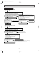
Page 29
A Check of power supply
Start
Check the connecting of main circuit parts and connector (CN501: I.P.M P. C. board,
CN 801: Electronic control P. C. board, CN554: relay P. C. board)
Turn on power supply
Is there voltage of 220V AC - 240V AC
in the power supply terminal block?
No
Check the power supply cable.
Yes
Is there voltage of 310V DC - 340V DC
across the smoothing capacity?
No
Is there voltage of 220V AC - 240V AC
No
across the output cable (LD63, LD64)
in the noise filter P. C. board?
Yes
Replace the noise
filter P. C. board
Yes
Replace the electronic control P. C. board.
Is there voltage of 220V AC - 240V AC
No
across the input terminal part in the
diode module (DS61)?
Yes
Check the main circuit parts
and replace it.
Replace the current
limiting resistor.
w When replacing, check the
connection of connector
CN720 in the outdoor
electronic control P. C.
board
B Check of serial signal
Start
1. Check the indoor unit with referring to the indoor unit service manual
2. Turn off the power supply of the indoor and outdoor unit and return the indoor/ outdoor unit
connecting wire to former original.
3. Check the connection of indoor/ outdoor unit connecting wire in the outdoor unit terminal block,
and check the connection of the connector (CN601: unit A, CN 602: unit B, CN603: unit C,
CN604: unit D) in the electronic control P. C. board
4. Disconnect the lead wire to the compressor. Turn on the power supply (indoor/ outdoor unit)
3 minutes later, EMERGENCY OPERATION starts.
Is there voltage of 5V DC - 10V DC between
No. 3 (+) and N (-) in the outdoor terminal block.
No
Replace the electronic control P. C. board.
Yes
Recheck a connected circumstance of the indoor/ outdoor unit connecting wire.
29
OB254-1.qxp
5/9/00 11:59 AM
Page 30
C Check of R. V. coil
• When heating operation does not work.
Start
1. Disconnect the lead wire leading to the compressor.
2. Turn on power supply to the indoor and outdoor unit, three minutes later
EMERGENCY OPERATION (HEAT operation) starts.
Is there voltage of 220V AC - 240V AC between
pin1 and pin 2 at connector CN913?
No
Yes
Turn off power supply of indoor and outdoor unit.
Disconnect the connector
CN913 in noise filter P. C.
board, and measure the
resistance of R. V. coil to
check the integrity.
No
Replace the R. V. coil
1. Turn off power supply of indoor and outdoor unit, and
disconnect the connector (CN851, CN852) in the electronic
control P. C. board.
2. Turn on power supply to the indoor and outdoor unit, three
minutes later EMERGENCY OPERATION
(HEAT operation) starts.
Is there voltage 12V DC between
the connector CN852 pin 1 (+)
and pin 5 (-)?
No
Replace the electronic
control P. C. board.
Yes
Yes
Replace the noise filter P. C. board.
Replace the 4-way valve
• When cooling operation does not work.
Start
1. Disconnect the lead wire leading to the compressor.
2. Turn on power supply to the indoor and outdoor unit, three minutes later
EMERGENCY OPERATION (COOL operation) starts.
Is there voltage of 220V AC - 240V AC between
pin1 and pin 2 at connector CN913?
No
Replace the 4-way valve
Yes
1. Turn off power supply of indoor and outdoor unit, and
disconnect the connector (CN851, CN852) in the electronic
control P. C. board.
2. Turn on power supply to the indoor and outdoor unit, three
minutes later EMERGENCY OPERATION
(COOL operation) starts.
Is there voltage 12V DC between
the connector CN852 pin 1 (+)
and CN851 pin 5 (-)? W1
Yes
No
Replace the noise filter P. C. board.
W1 If the connector CN913 is not connected or R. V. coil is open, voltage
occurs between terminals even when the control is OFF.
Replace the electronic control P. C. board.
30
OB254-1.qxp
5/9/00 11:59 AM
Page 31
D Check of LEV
Start
Turn on power supply to the outdoor unit after checking LEV coil is mounted to the
LEV body securely.
Yes
Is "click - click" sound heard?
Or, do you feel vibration of the LEV coil with a hand?
Nomal
No
Disconnect the connector
(CN791: unit A, CN792: unit B, CN793: unit C,
CN794: unit D), and measure the resistance of
LEV coil to check the integrity.
Yes
Replace the electronic
control P. C. board
No
Replace the LEV coil.
E Check of inverter/ compressor
Start
Disconnect the lead wire to the compressor at terminals, and turn on power supply to the indoor
and outdoor unit. Three minutes later, EMERGENCY OPERATION starts.
Measure the voltage between
each leading to the compressor.
U (BLK) - V (WHT)
V (WHT) - W (RED)
W (RED) - U (BLK)
Output voltage
COOL: 100V(58Hz) HEAT: 100V(58Hz)
Is voltage output? W1
Yes
No
Is output balanced?
Yes
W1 • After the outdoor fan starts running, wait for 1 minutes or more before
measuring the voltage.
• The output voltage values in the above table have the tolerance of i20%.
No
Turn off power supply of indoor and outdoor unit,
and measure the compressor winding resistance
between the compressor terminals.
Is there resistance of 0.27" to 0.34" between
the each terminals?
Yes
LED indicator the inverter
stops due to over current?
No
1. Turn off power supply of the indoor
and outdoor unit, and disconnect
the connector CN 551 in the relay
P. C. board
2. Turn on power supply to the outdoor
unit, and after 1 minutes or more
passed, check the resistance
between the connector
CN551 pin 1 and pin 2.
0"
Check the resistance
between each terminal
Yes
Replace the electronic
control P. C. board
with the I.P.M P. C. board.
No
Infinite
Replace the
compressor.
After 1 minutes has passed since the
power supply of outdoor unit was
turned off, disconnect the connector
CN 553 in the noise filter P. C. board.
Return the lead wire of compressor to former, and
turn on power supply to indoor and outdoor unit.
Three minutes later EMERGENCY OPERATION starts.
0"
Clarify the causes by counting time until the inverter stops.
0 to 10 seconds: compressor rare short
10 to 60 seconds: compressor lock
60 seconds to 5minutes: refrigerant circuit defective
5 minutes or more: normal
Check the resistance
HPS (63H2).
Infinite
Replace the
relay P. C. board.
31
Replace the
HPS (63H2).
OB254-1.qxp
5/9/00 11:59 AM
Page 32
F Check of thermistor
Start
Abnormal
Disconnect the connector in the electronic control P. C. board (see below table), and
measure the resistance of thermistor to check whether the thermistor is normal or not.
Replace the thermistor
Normal
Reconnect the connector (CN661, CN662 and CN663) and disconnect the lead wire leading to the compressor.
Turn on power supply to the indoor and outdoor unit. Three minutes later EMERGENCY OPERATION starts.
Does thermistor operate 10 minutes or more though the
thermistor abnormality is not displayed?
No
Replace the electronic
control P. C. board.
Yes
Normal
Thermistor
Defrost thermistor
Discharge temperature thermistor
Evaporation temperature thermistor
Gas pipe temperature thermistor (Unit A)
Gas pipe temperature thermistor (Unit B)
Gas pipe temperature thermistor (Unit C)
Gas pipe temperature thermistor (Unit D)
Fin temperature thermistor
Connector, Pin No.
Between CN661 pin1 and pin2
Between CN661 pin3 and pin4
Between CN661 pin5 and pin6
Between CN662 pin1 and pin2
Between CN662 pin3 and pin4
Between CN662 pin5 and pin6
Between CN662 pin7 and pin8
Between CN663 pin1 and pin2
Symbol
RT62
RT61
RT63
RT66
RT67
RT68
RT69
RT65
G Check of fan motor
Start
Check the connection of connector (CN851, CN852) in the fan motor relay connector and electronic control P. C. board
at the noise filter P. C. board and connector (CN901, CN902) in the noise filter board.
Disconnect the fan motor connector, and measure the resistance of the
fan motor winding to check the winding characteristic.
Abnormal
Replace the fan motor
Normal
1. Disconnect the lead wire leading to the compressor. Turn on power supply to the
indoor and outdoor unit. Three minutes later, EMERGENCY OPERATION starts.
2. Check the voltage between pin 2 and pin 3, pin 2 and pin 5, pin 2 and pin 6 at the fan motor connector.
Is there voltage of 220V AC - 240V AC?
Yes
No
1. Turn off power supply of the indoor and outdoor unit, and disconnect the connector
(CN851, CN852).
2. Is the voltage 0V, when the voltage between CN852 pin1 (+) and CN851 pin1 (-),
pin2 (-), or pin3 (-) are measured after the power supply is turned on the outdoor unit?
No
Yes
Is there voltage of 12V DC between CN852 pin1 (+) and pin3 (-), when power supply
turns on the indoor unit and EMERGENCY OPERATION starts in three minutes.
Yes
Replace the noise filter P. C. board
32
No
Replace the electronic
control P. C. board
OB254-2.qxp
5/9/00 12:01 PM
Page 33
H Check of HPS
Start
1. Disconnect the connector CN722 in the electronic control P. C. board.
2. Check the resistance of HPS after 1 minutes have passed since the outdoor unit power supply was turnd off.
Infinity
Check the resistance between
each terminal?
Replace HPS (63H1).
0"
Return CN722 to former.
Turn on power supply to the indoor and outdoor unit.
3 minutes lator, EMERGENCY OPERATION starts.
Yes
Is HPS protection displayed
immediately after compressor
starts.
No
Replace the electronic control P. C. board.
Yes
Normal
I The other cases
In the case that the indoor fan and outdoor fan operate but the compressor does not operate, it causes that the
high pressure switch can be operated once.
First of all, check the high pressure switch can be shorted, turn OFF the power and turn ON again 1 minute later.
Indoor unit dose not operate. (difference modes)
• When you try to run two indoor unit simultaneously, one for cooling and the other for heating, the unit which
transmits signal to the outdoor units earlier decides the operation mode. The other unit indicates as shown in
the figure below.
• When the above situation occurs, set all the indoor units to the same mode, turn OFF the indoor units, and
then turn them back ON.
• Though the top of the indoor unit sometimes gets warm, this does not mean malfunction. The reason is that
the refrigerant gas continuously flows into the indoor unit even while it is not operating.
OPERATION INDICATOR
Lighting
Flashing
33
Page 34
TEST POINT DIAGRAM AND VOLTAGE
MXZ-32SV - E1
Electronic control P.C.board
Gas pipe temperature thermistor
Evaporation temperature thermistor
Defrost temperature thermistor
Discharge temperature thermistor
Resistance (')
5/9/00 12:02 PM
Resistance (')
OB254-2.qxp
Temperature(;)
Discharge temperature thermistor
0.3~0.6V DC
Defrost temperature thermistor
2.5~4.0V DC
Evaporation temperature thermistor
2.5~4.0V DC
Temperature(;)
Outdoor fan ON 12V DC
Outdoor fan Lo 12V DC
Outdoor fan Me 12V DC
Serial signal Room D 5~10V DC
R.V. coil
12V DC
{
Serial signal Room B
5~10V DC
{
{
Resistance (')
Serial signal Room C 5~10V DC
{
Fin temperature thermistor
1.0~4.0V DC
Serial signal Room A
5~10V DC
Relay 12V DC
{
-
12V DC {
+
-
0~5V DC
5V DC
{
LED monitor indication
Room D
Room C
Room B
Room A
Gas pipe temperature
thermistor 2.5~4.0V DC
34
{
Temperature(;)
High pressure switch
Liner expansion valve(LEV)
12V DC pulse wave
5/9/00 12:02 PM
Page 35
Noise filter P.C.board
OUTDOOR FAN
220V-240V AC
{
{
{
REVERSING VALVE 220V-240V AC
220V-240V AC
OUTPUT
220V-240V AC
INPUT
{
I.P.M P.C.board
12V DC
{
{
12V DC
{
Relay P.C.board
{
12V DC
High pressure
switch
{
12V DC
{
{
OB254-2.qxp
Short
35
320V DC
OB254-2.qxp
13
5/9/00 12:03 PM
Page 36
DISASSEMBLY INSTRUCTIONS
13-1 MXZ-32SV - E1
OUTDOOR UNIT
OPERATING PROCEDURE
PHOTOS
1.Removing the compressor
(1)Remove the screws fo the service panel, and remove it.
Release refrigerant gas.
(2)Remove the screws of the top panel , and remove it.
(3)Remove the screws of the front panel , and remove it.
(4)Disconnect the compressor lead wire.(TAB64,TAB65,TAB66)
(5)Disconnect the ourdoor electronic control P.C. board
connectors CN791, CN792, CN793, CN794, CN662,
CN722, and CN661.Disconnect the noise filter P.C. board
connectors CN913.
(6)Remove the four screws of the electrical parts , and remove
them.
(7)Remove the propeller.
(8)Remove the screws of the separator, and remove it.
(9)Detach the brazed joints of the compressor suction and discharge pipes.(See Photo 3.)
(10)Remove the three compressor nuts and remove the compressor.
Photo 1
Top panel
Service panel
Front
panel
Photo 2
Control P.C.board
Electrical parts
Sepatator
Terminal
Photo 3
Discharge pipe
brazed part
Suction pipe
braxed part
36
OB254-2.qxp
5/9/00 12:03 PM
Page 37
OPERATING PROCEDURE
PHOTOS
2.Removing the fan motor
(1)Remove the top panel(five screws),the service panel(four
screws),and the front panel (two screws).(See Photo 1.)
(2)Disconnect the connector CN911 on the outdoor controller
board.
(3)Remove the propeller.
(4)Remove the fan motor.
3.Removing the 4-way valve
(1)Remove the screws of the top panel , and remove it.(See
Photo 1.)
(2)Remove the service panel,rear panel,and connect cover
panel.Release refrigerant gas.
(3)Remove the electrical parts.(See Photo 2.)
(4)Detach the brazed joint of 4-way valve and pipe.(See Photo
4.)
Photo 4
4 way valve
R. V. coil
Brazing area
4.Removing the linear expansion valve
(1)Remove the service panel.(See Photo 1.)
(Gas release is not required if the unit is pumped down.)
(2)Remove the coil of linear expansion valve.
(3)Detach the brazed joint of linear expansion valve and pipe.
Photo 5
LEV coils
37
Linear
expansion
valves
OB254-2.qxp
5/9/00 12:03 PM
Page 38
OPERATING PROCEDURE
PHOTOS
5.Removing the reactor
(1)Remove the five screws of the top panel , and remove it.(See
Photo 1.)
(2)Disconnect the reactor lead wire.
(3)Remove the two screws of the reactor , and take it out.
38
Photo 6
Reactor
OB254-2.qxp
5/9/00 12:03 PM
14
Page 39
PARTS LIST
14-1. OUTDOOR UNIT FUNCTIONAL PARTS
MXZ-32SV - E1
Part numbers that are circled are not shown in the illustration.
Symbol
No.
Parts No.
Parts Name
in Wiring
Diagram
1
2
3
4
5
6
7
8
9
MXZ-32SV- E1
Remarks
1
M21 17A 501 PROPELLER FAN
T2W E40 301 OUTDOOR FAN MOTOR
T2W E40 452 I.P.M P.C. BOARD
MF61
1
1
M21 17A 447 DIODE STACK
M21 17A 443 DIODE MODULE
M21 17E 337 REACTOR
T2W E40 357 POWER FACTOR CAPACITOR
T2W E40 356 SMOOTHING CAPACITOR
T2W E70 451 ELECTRONIC CONTROL P.C. BOARD
DS62
1
DS61
1
L
1
C61
1
220+ 400V
C62,C63
2
2500+ 400V
1
10 T2W E67 424 NOISE FILTER P.C. BOARD
11 T2W E65 376 TERMINAL BLOCK
1
TB3
4
TB2
1
X64
1
RT66,67,68,69
1
RT65
1
12 T2W E65 375 TERMINAL BLOCK
13 M21 42A 340 RELAY
14 T2W E70 307 GAS PIPE TEMPERATUR THERMISTOR
15 M21 42A 308 FIN TEMPERATURE THERMISTOR
Q'ty / unit
16 M21 17A 362 RESISTOR
17 T2W E70 308 THERMISTOR SET
18 T2W E70 398 R. V. COIL
19 T2W E40 441 RELAY P.C. BOARD
R
1
RT61, 62, 63
1
21S4
1
1
F801,F911
20 T2W E66 382 FUSE
39
2
A,B,C,D
EVAPORATION
DISCHARGE, DEFROST
OB254-2.qxp
5/9/00 12:03 PM
Page 40
14-2. OUTDOOR UNIT STRUCTURAL PARTS
MXZ-32SV - E1
1
3 17
5
9
4
8
6
7
11
2
15 14 12 13 16
18
Part numbers that are circled are not shown in the illustration.
Symbol
No.
Parts No.
Parts Name
in Wiring
Diagram
Q'ty / unit
Remarks
MXZ-32SV- E1
1
M21 AS2 232 FRONT PANLE
1
2
M21 17A 245 SERVICE PANEL
1
3
M21 17A 249 SIDE PANEL
1
4
M21 17A 297 TOP PANEL
1
5
T2W E40 523 REAR GUARD
1
6
T2W E70 248 REAR PANEL
1
7
T2W E40 247 PIPE COVER
1
8
M21 48A 961 4-WAY VALVE
9
T2W E79 646 HIGH PRESSURE SWICH
63H1
1
2.75MPa(28kg/cm3)
10 T2W E40 646 HIGH PRESSURE SWICH
63H2
1
3.43MPa(35kg/cm3)
1
1/2,3/8,1/4 SET
1
11 M21 42E 644 UNION
12 T2W E70 651 EXPANSION VALVE
LEV A
1
A room
13 T2W E70 652 EXPANSION VALVE
LEV B
1
B room
14 T2W E70 653 EXPANSION VALVE
LEV C
1
C room
LEV D
1
D room
15 T2W E70 654 EXPANSION VALVE
16 M21 AS2 290 BASE ASSEMBLY
1
17 M21 42E 630 HEAT EXCHANGER
1
18 T92 500 800 COMPRESSOR
1
THV-247FBA
19 M21 986 936 CAPILLARY TUBE([4.0O[2.4O2000)
3
[4.0O[2.4O400
20 M21 LV0 936 CAPILLARY TUBE SET([3.0O[2.0O200)
4
[3.0O[2.0O200 4PCS/SET
21 T2W E59 936 CAPILLARY TUBE ([2.5O[0.6O1000)
2
[2.5O[0.6O1000
[2.5O[0.6O750
MC
When servicing , cut the tube to the proper length as shown in the REFRIGERANT SYSTEM DIAGRAM.
See page 12.
40
OB254-2.qxp
5/9/00 12:03 PM
Page 41
14-3. ACCESSORY PARTS
MXZ-32SV - E1
1
No.
1
Parts No.
T2W E59 704
Parts Name
Symbol
Q'ty / unit
in Wiring
MXZ-32SV
Diagram
E1
1
DRAIN SOCKET ASSEMBLY
41
Remarks
DRAIN SOCKET O1
DRAIN CAP O2
OB254-2.qxp
5/9/00 12:03 PM
15
Page 42
OPTIONAL PARTS
15-1. Different-diameter pipe
Unit : mm (inch)
MXZ-32SV
For differentdiameter
pipes
Model name
Model code
Connected pipes
diameter (mm)
Length
A
Length
B
Length
C
MAC-454JP
51H-454
{9.52 — {12.7
(3/8)
(1/2)
{9.52
(3/8)
{12.7
(1/2)
69
MAC-455JP
51H-455
{12.7 — {9.52
(1/2)
(3/8)
{12.7
(1/2)
{9.52
(3/8)
65
MAC-456JP
516456
{12.7 — {15.88
(1/2)
(5/8)
{12.7
(1/2)
{15.88
(5/8)
66.5
15-2. Outlet guide
Changes air discharge direction.
Applied unit
Model name
Model code
MXZ-32SV
MAC-855SG
51H-855
109.4
51.8
29.2
150
5 - [6
Punxhed hole
29.2
5 - [6
Punxhed hole
6.4
386
760.8
832
760.8
416
6.4
610.4
534
386
534
MAC-855SG
42
A
B
C
OB254-2.qxp
5/9/00 12:03 PM
Page 43
OB254-2.qxp
5/9/00 12:03 PM
Page 44
HEAD OFFICE MITSUBISHI DENKI BLDG.MARUNOUCHI TOKYO100-8310 TELEX J24532 CABLE MELCO TOKYO
C Copyright 2000 MITSUBISHI ELECTRIC ENGINEERING CO.,LTD
Issued in May. 2000. No.OB254 523
Printed in Japan
New publication, effective May. 2000
Specifications subject to change without notice.