1
Veriton 3500/5500/7500
Service Guide
Service guide files and updates are available
on the AIPG/CSD web; for more information,
please refer to http://csd.acer.com.tw
PART NO.:
PRINTED IN TAIWAN
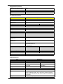
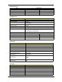
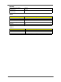
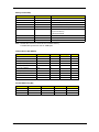
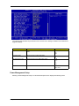
Revision History
Please refer to the table below for the updates made on Veriton 3500/5500/7500 service guide.
Date
II
Chapter
Updates
Copyright
Copyright © 2002 by Acer Incorporated. All rights reserved. No part of this publication may be reproduced,
transmitted, transcribed, stored in a retrieval system, or translated into any language or computer language, in
any form or by any means, electronic, mechanical, magnetic, optical, chemical, manual or otherwise, without
the prior written permission of Acer Incorporated.
Disclaimer
The information in this guide is subject to change without notice.
Acer Incorporated makes no representations or warranties, either expressed or implied, with respect to the
contents hereof and specifically disclaims any warranties of merchantability or fitness for any particular
purpose. Any Acer Incorporated software described in this manual is sold or licensed "as is". Should the
programs prove defective following their purchase, the buyer (and not Acer Incorporated, its distributor, or its
dealer) assumes the entire cost of all necessary servicing, repair, and any incidental or consequential
damages resulting from any defect in the software.
Acer is a registered trademark of Acer Corporation.
Intel is a registered trademark of Intel Corporation.
Pentium and Pentium IV are trademarks of Intel Corporation.
Other brand and product names are trademarks and/or registered trademarks of their respective holders.
III
Conventions
The following conventions are used in this manual:
IV
Screen messages
Denotes actual messages that appear
on screen.
NOTE
Gives bits and pieces of additional
information related to the current
topic.
WARNING
Alerts you to any damage that might
result from doing or not doing specific
actions.
CAUTION
Gives precautionary measures to
avoid possible hardware or software
problems.
IMPORTANT
Reminds you to do specific actions
relevant to the accomplishment of
procedures.
Preface
Before using this information and the product it supports, please read the following general information.
1.
This Service Guide provides you with all technical information relating to the BASIC CONFIGURATION
decided for Acer's "global" product offering. To better fit local market requirements and enhance product
competitiveness, your regional office MAY have decided to extend the functionality of a machine (e.g.
add-on card, modem, or extra memory capability). These LOCALIZED FEATURES will NOT be covered
in this generic service guide. In such cases, please contact your regional offices or the responsible
personnel/channel to provide you with further technical details.
2.
Please note WHEN ORDERING FRU PARTS, that you should check the most up-to-date information
available on your regional web or channel. If, for whatever reason, a part number change is made, it will
not be noted in the printed Service Guide. For ACER-AUTHORIZED SERVICE PROVIDERS, your Acer
office may have a DIFFERENT part number code to those given in the FRU list of this printed Service
Guide. You MUST use the list provided by your regional Acer office to order FRU parts for repair and
service of customer machines.
V
VI
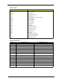
Table of Contents
Chapter 1
System Specifications
1
Overview . . . . . . . . . . . . . . . . . . . . . . . . . . . . . . . . . . . . . . . . . . . . . . . . . . . . . . . .1
Features . . . . . . . . . . . . . . . . . . . . . . . . . . . . . . . . . . . . . . . . . . . . . . . . . . . . . . .2
Front Panel-Veriton 3500/3500G . . . . . . . . . . . . . . . . . . . . . . . . . . . . . . . . . . . . .4
Rear Panel-Veriton 3500/3500G . . . . . . . . . . . . . . . . . . . . . . . . . . . . . . . . . . . . .6
Front Panel-Veriron 5500/5500G . . . . . . . . . . . . . . . . . . . . . . . . . . . . . . . . . . . . .8
Rear Panel-Veriton 5500/5500G . . . . . . . . . . . . . . . . . . . . . . . . . . . . . . . . . . . .10
Front Panel-Veriton 7500/7500G . . . . . . . . . . . . . . . . . . . . . . . . . . . . . . . . . . . .12
Rear Panel-Veriton 7500/7500G . . . . . . . . . . . . . . . . . . . . . . . . . . . . . . . . . . . .14
System Block Diagram (Veriton 3500/ 5500/ 7500) . . . . . . . . . . . . . . . . . . . . . .16
System Block Diagram (Veriton 3500G/ 5500G/ 7500G) . . . . . . . . . . . . . . . . . .17
Main Board Layout (Veriton 3500/ 5500/ 7500) (S88M/ GL) . . . . . . . . . . . . . . .18
Main Board Layout (Veriton 3500G/5500G/7500G) (S88M/ G) . . . . . . . . . . . . .19
Keyboard (3500/ 3500G, 5500/ 5500G, 7500/ 7500G) . . . . . . . . . . . . . . . . . . . .21
Hardware Specifications and Configurations . . . . . . . . . . . . . . . . . . . . . . . . . . .23
Power Management Functions . . . . . . . . . . . . . . . . . . . . . . . . . . . . . . . . . . . . . .34
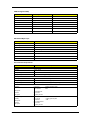
Chapter 2
System Utilities
36
Entering Setup . . . . . . . . . . . . . . . . . . . . . . . . . . . . . . . . . . . . . . . . . . . . . . . . . .37
Product Information . . . . . . . . . . . . . . . . . . . . . . . . . . . . . . . . . . . . . . . . . . . . . .38
Standard CMOS Features . . . . . . . . . . . . . . . . . . . . . . . . . . . . . . . . . . . . . . . . .39
IDE Primary Master/Slave and IDE Secondary Master/Slave Setup . . . . .41
Advanced BIOS Features . . . . . . . . . . . . . . . . . . . . . . . . . . . . . . . . . . . . . . . . . .42
Advanced Chipset Features . . . . . . . . . . . . . . . . . . . . . . . . . . . . . . . . . . . . . . . .44
Integrated Peripherals . . . . . . . . . . . . . . . . . . . . . . . . . . . . . . . . . . . . . . . . . . . .45
Power Management Setup . . . . . . . . . . . . . . . . . . . . . . . . . . . . . . . . . . . . . . . . .48
PnP/PCI Configurations . . . . . . . . . . . . . . . . . . . . . . . . . . . . . . . . . . . . . . . . . . .51
PC Health Status . . . . . . . . . . . . . . . . . . . . . . . . . . . . . . . . . . . . . . . . . . . . . . . .53
Frequency Control . . . . . . . . . . . . . . . . . . . . . . . . . . . . . . . . . . . . . . . . . . . . . . .55
System Security . . . . . . . . . . . . . . . . . . . . . . . . . . . . . . . . . . . . . . . . . . . . . . . . .56
Supervisor Password . . . . . . . . . . . . . . . . . . . . . . . . . . . . . . . . . . . . . . . . .56
User Password . . . . . . . . . . . . . . . . . . . . . . . . . . . . . . . . . . . . . . . . . . . . . .58
Bypassing the Password . . . . . . . . . . . . . . . . . . . . . . . . . . . . . . . . . . . . . . .59
Load Default Settings . . . . . . . . . . . . . . . . . . . . . . . . . . . . . . . . . . . . . . . . . . . . .60
Exiting Setup . . . . . . . . . . . . . . . . . . . . . . . . . . . . . . . . . . . . . . . . . . . . . . . . . . . .61
Advanced Options . . . . . . . . . . . . . . . . . . . . . . . . . . . . . . . . . . . . . . . . . . . . . . .62
Product Information . . . . . . . . . . . . . . . . . . . . . . . . . . . . . . . . . . . . . . . . . . .62
Advanced BIOS Features . . . . . . . . . . . . . . . . . . . . . . . . . . . . . . . . . . . . . .63
Advanced Chipset Features . . . . . . . . . . . . . . . . . . . . . . . . . . . . . . . . . . . .64
Integrated Peripherals . . . . . . . . . . . . . . . . . . . . . . . . . . . . . . . . . . . . . . . . .65
Power Management Setup . . . . . . . . . . . . . . . . . . . . . . . . . . . . . . . . . . . . .66
Frequency Control . . . . . . . . . . . . . . . . . . . . . . . . . . . . . . . . . . . . . . . . . . .68
Chapter 3
Machine Disassembly and Replacement
70
General Information . . . . . . . . . . . . . . . . . . . . . . . . . . . . . . . . . . . . . . . . . . . . . .71
Before You Begin . . . . . . . . . . . . . . . . . . . . . . . . . . . . . . . . . . . . . . . . . . . .71
Veriton 3500/ 3500G Disassembly Flow Chart . . . . . . . . . . . . . . . . . . . . . . . . . .72
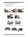
Disassembling the Veriton 3500/ 3500G . . . . . . . . . . . . . . . . . . . . . . . . . . . . . .73
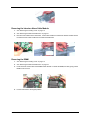
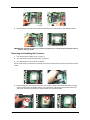
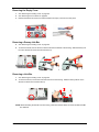
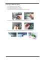
Opening the Housing . . . . . . . . . . . . . . . . . . . . . . . . . . . . . . . . . . . . . . . . .73
Removing the Front Panel . . . . . . . . . . . . . . . . . . . . . . . . . . . . . . . . . . . . .74
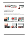
Removing the AGP VGA Card . . . . . . . . . . . . . . . . . . . . . . . . . . . . . . . . . .74
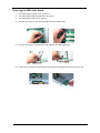
Removing the LAN Card . . . . . . . . . . . . . . . . . . . . . . . . . . . . . . . . . . . . . . .75
Removing the EMI Audio Cover . . . . . . . . . . . . . . . . . . . . . . . . . . . . . . . . .75
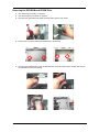
Removing the FDD and DVD Frame . . . . . . . . . . . . . . . . . . . . . . . . . . . . .75
VII
Table of Contents
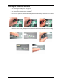
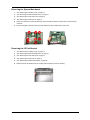
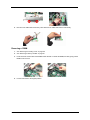
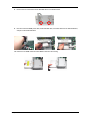
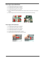
Removing the Intrusion Alarm Cable Module . . . . . . . . . . . . . . . . . . . . . . 77
Removing the DIMM . . . . . . . . . . . . . . . . . . . . . . . . . . . . . . . . . . . . . . . . . .77
Removing and Installing the RTC Battery . . . . . . . . . . . . . . . . . . . . . . . . . .78
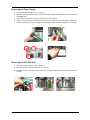
Removing the Power Switch Cable . . . . . . . . . . . . . . . . . . . . . . . . . . . . . . .78
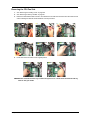
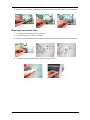
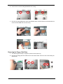
Removing the USB/ Audio Board . . . . . . . . . . . . . . . . . . . . . . . . . . . . . . . .79
Removing the Hard Disk Drive . . . . . . . . . . . . . . . . . . . . . . . . . . . . . . . . . .80
Removing the LED Activity Indicators . . . . . . . . . . . . . . . . . . . . . . . . . . . . .81
Removing the Power Supply . . . . . . . . . . . . . . . . . . . . . . . . . . . . . . . . . . . .82
Removing the CPU Fan Sink . . . . . . . . . . . . . . . . . . . . . . . . . . . . . . . . . . .82
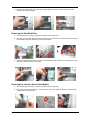
Removing and Installing the Processor . . . . . . . . . . . . . . . . . . . . . . . . . . .83
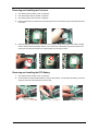
Removing the System Main board . . . . . . . . . . . . . . . . . . . . . . . . . . . . . . .84
Removing the I/O Port Bracket . . . . . . . . . . . . . . . . . . . . . . . . . . . . . . . . . .84
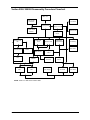
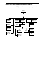
Veriton 5500/ 5500G Disassembly Procedure Flowchart . . . . . . . . . . . . . . . . . .85
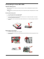
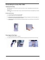
Disassembling the Veriton 5500/ 5500G . . . . . . . . . . . . . . . . . . . . . . . . . . . . . .86
Open the Housing Cover . . . . . . . . . . . . . . . . . . . . . . . . . . . . . . . . . . . . . .86
Removing the Front Panel . . . . . . . . . . . . . . . . . . . . . . . . . . . . . . . . . . . . .86
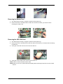
Removing the Empty Cover . . . . . . . . . . . . . . . . . . . . . . . . . . . . . . . . . . . .87
Removing a Dummy Link Bar . . . . . . . . . . . . . . . . . . . . . . . . . . . . . . . . . . .87
Removing a Link Bar . . . . . . . . . . . . . . . . . . . . . . . . . . . . . . . . . . . . . . . . . .87
Removing the AGP VGA Card . . . . . . . . . . . . . . . . . . . . . . . . . . . . . . . . . .88
Removing the Modem Card . . . . . . . . . . . . . . . . . . . . . . . . . . . . . . . . . . . .88
Removing the USB/ Audio Board Module . . . . . . . . . . . . . . . . . . . . . . . . . .88
Removing a DIMM . . . . . . . . . . . . . . . . . . . . . . . . . . . . . . . . . . . . . . . . . . .89
Removing the CPU Fan Sink . . . . . . . . . . . . . . . . . . . . . . . . . . . . . . . . . . .90
Removing and Installing the Processor . . . . . . . . . . . . . . . . . . . . . . . . . . .91
Removing and Installing the RTC Battery . . . . . . . . . . . . . . . . . . . . . . . . . .91
Removing the Hard Diskette Drive and Floppy Diskette Drive . . . . . . . . . .92
Removing the CD-RW & DVD-ROM Drive . . . . . . . . . . . . . . . . . . . . . . . . .93
Removing the Power Supply . . . . . . . . . . . . . . . . . . . . . . . . . . . . . . . . . . . .95
Removing the Intrusion Alarm Cable Module . . . . . . . . . . . . . . . . . . . . . . .95
Removing the LED Activity Indicators Module . . . . . . . . . . . . . . . . . . . . . .95
Removing Power Switch Cable . . . . . . . . . . . . . . . . . . . . . . . . . . . . . . . . . .96
Removing the System Main Board . . . . . . . . . . . . . . . . . . . . . . . . . . . . . . .97
Removing the I/O Port Bracket . . . . . . . . . . . . . . . . . . . . . . . . . . . . . . . . . .97
Veriton 7500/ 7500G Disassembly Procedure Flowchart . . . . . . . . . . . . . . . . . .98
Disassembling the Veriton 7500/ 7500G . . . . . . . . . . . . . . . . . . . . . . . . . . . . . .99
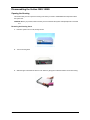
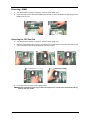
Opening the Housing . . . . . . . . . . . . . . . . . . . . . . . . . . . . . . . . . . . . . . . . .99
Removing the Front Panel . . . . . . . . . . . . . . . . . . . . . . . . . . . . . . . . . . . . .99
Removing the Modem Card . . . . . . . . . . . . . . . . . . . . . . . . . . . . . . . . . . .100
Removing the AGP VGA Card . . . . . . . . . . . . . . . . . . . . . . . . . . . . . . . . .100
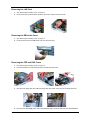
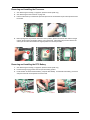
Removing the USB/ Audio Board . . . . . . . . . . . . . . . . . . . . . . . . . . . . . . .101
Removing the DVD-ROM and CD-RW Drive . . . . . . . . . . . . . . . . . . . . . .102
Removing the Floppy Disk Drive . . . . . . . . . . . . . . . . . . . . . . . . . . . . . . .103
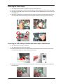
Removing the Hard Disk Drive . . . . . . . . . . . . . . . . . . . . . . . . . . . . . . . . .104
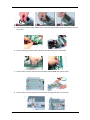
Removing the Intrusion Alarm Cable Module . . . . . . . . . . . . . . . . . . . . . .104
Removing a DIMM . . . . . . . . . . . . . . . . . . . . . . . . . . . . . . . . . . . . . . . . . .105
Removing the CPU Fan Sink . . . . . . . . . . . . . . . . . . . . . . . . . . . . . . . . . .105
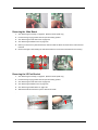
Removing and Installing the Processor . . . . . . . . . . . . . . . . . . . . . . . . . .106
Removing and Installing the RTC Battery . . . . . . . . . . . . . . . . . . . . . . . . .106
Removing the Power Supply . . . . . . . . . . . . . . . . . . . . . . . . . . . . . . . . . . .107
Removing the LED Activity Indicators With Power Switch Cable Module .107
Removing the Main Board . . . . . . . . . . . . . . . . . . . . . . . . . . . . . . . . . . . .108
Removing the I/O Port Bracket . . . . . . . . . . . . . . . . . . . . . . . . . . . . . . . . .108
VIII
Table of Contents
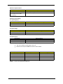
Chapter 4
Troubleshooting
110
Power-On Self-Test (POST) . . . . . . . . . . . . . . . . . . . . . . . . . . . . . . . . . . . . . . .111
POST Error Messages List . . . . . . . . . . . . . . . . . . . . . . . . . . . . . . . . . . . . . . . .117
Error Symptoms List . . . . . . . . . . . . . . . . . . . . . . . . . . . . . . . . . . . . . . . . . . . . .119
Undetermined Problems . . . . . . . . . . . . . . . . . . . . . . . . . . . . . . . . . . . . . . . . . .123
Chapter 5
Jumper and Connector Information
124
Jumpers and Connectors . . . . . . . . . . . . . . . . . . . . . . . . . . . . . . . . . . . . . . . . .124
Connector Description . . . . . . . . . . . . . . . . . . . . . . . . . . . . . . . . . . . . . . .127
Chapter 6
FRU (Field Replaceable Unit) List
128
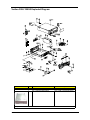
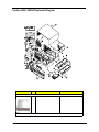
Veriton 3500/ 3500G Exploded Diagram . . . . . . . . . . . . . . . . . . . . . . . . . . . . .129
Veriton 5500/ 5500G Exploded Diagram . . . . . . . . . . . . . . . . . . . . . . . . . . . . .135
Veriton 7500/ 7500G Exploded Diagram . . . . . . . . . . . . . . . . . . . . . . . . . . . . .141
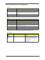
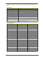
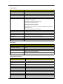
Appendix A
Model Definition and Configuration
147
Veriton 3500/5500/7500 . . . . . . . . . . . . . . . . . . . . . . . . . . . . . . . . . . . . . . . . . .147
Veriton 3500G/5500G/7500G . . . . . . . . . . . . . . . . . . . . . . . . . . . . . . . . . . . . . .148
Main Features . . . . . . . . . . . . . . . . . . . . . . . . . . . . . . . . . . . . . . . . . . . . . . . .149
Appendix B
Test Compatible Components
150
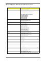
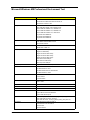
Microsoft Windows XP Professional Environment Test . . . . . . . . . . . . . . . . . .151
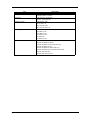
Microsoft Windows ME Professional Environment Test . . . . . . . . . . . . . . . . . .153
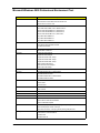
Microsoft Windows 2000 Professional Environment Test . . . . . . . . . . . . . . . . .155
Linux Red Hat Environment Test . . . . . . . . . . . . . . . . . . . . . . . . . . . . . . . . . . .157
Appendix C
Index
Online Support Information
160
162
IX
Chapter 1
System Specifications
Overview
The Veriton 3500, 5500, 7500 supports Intel® Pentium IV (Willamette 478/Northwood) Flip Chip-Pin Grid Array
2 processor (FC-PGA2) based Micro ATX, IBM PC/AT compatible system with PCI bus.
The Veriton 3500G, 5500G, 7500G supports Intel® Pentium IV (Willamette 478/Northwood) Flip Chip-Pin Grid
Array 2 processor (FC-PGA2) based Micro ATX, IBM PC/AT compatible system with PCI/ AGPbus.
Chapter 1
1
Features
Performance
!
Intel Pentium® IV processor with Intel NetBurst™ micro-architecture and integrated 256KB/
512KB embedded L2 cache memory in Flip Chip 2 (FC)-mPGA 478 socket form factor, with
supporting CPU clock up to 2.4GHz+.
!
System Front Side bus speed:400/533 MHz for Brookdale G and 400MHz for Brookdale GL.
!
Supports 2 DIMM sockets up to 2GB using DDR (Double Data Rate) SDRAM DIMM modules.
!
Integrated LAN Controller (ICH4+PLC82562ET).
!
3.5-inch and 5.25-inch floppy disk drives.
!
CD-ROM, DVD-ROM or CD-RW drive
!
1.5 V AGP interface with 4X SBA/ Data Transfer and 2X/ 4X Fast Write capability ( no AGP slot for
Veriton 3500, 5500 and 7500).
!
High capacity, Enhanced-IDE hard disk
!
Power management features
!
CPU SMM (System Management Mode), STOP clock control
!
On-board PCI master enhanced local bus IDE (Embedded in 82801DB chipset).
!
PIO mode 4
!
Multiword DMA Mode 2
!
Ultra DMA/33, Ultra DMA/66 & Ultra DMA/100 modes
!
Plug-and-Play (PnP) feature
!
ACPI 1.0 b Compliant Power management and Configuration Support
!
Software shutdown for Windows 95/98SE/ME/2000/XP
!
Hardware monitor function
!
On-board DC-to-DC converter (VRM 9.0 spec)
!
Supports USB 2.0 high-performance peripherals
Multimedia
!
128-bit graphics accelerator installed in the AGP Pro card slot (AGP slot: not available for Veriton
3500, 5500 and 7500)
!
Cathode-ray tube (CRT) support
!
Liquid crystal display (LCD) support (optional)
!
An additional AGP card 1.5V slot, supports 1X, 2X and 4X
!
3-D quality audio system via onboard audio controller
!
Audio-in/Line-in, Audio-out/Line-out, Headphone-out, Microphone-in, and Game/MIDI interface
NOTE: The system has two microphone-in jacks (front and rear). However, you can not use both of them at
the same time. By default, your system enables the microphone-in jack in front and disables the one at the
back.
Connectivity
2
!
One AGP and three PCI slots (AGP slot for Veriton 3500G, 5500G and 7500G only)
!
USB and PS/2 compatible mouse and keyboard interfaces
!
Two high-speed NS 16C550-compatible serial ports
!
One multi-mode parallel port
!
Six USB ports ( 2 available on front panel and 4 on rear panel) with Plug and Play function
Veriton 3500/5500/7500
!
High-speed 56K V9.0 fax/data/voice PCI modem (optional)
!
One RJ45 connector supports IEEE 802.3./802.3u 10Base-T/100Base-TX-compatible network
with remote wake-up function (WfM 2.0 Complaint)
Expansion
!
3 PCI slots + 2 DIMM slots+ 1 AGP slot (no AGP slot for Veriton 3500, 5500 and 7500)
!
Upgradeable memory and hard disk
Human-centric design and ergonomics
Chapter 1
!
Mini-tower form factor
!
Separate computer stand and rubber stands for quick and easy positioning
!
Space-saver solution
!
Accessible I/O ports
!
Smooth and stylish design
!
Low emission and low radiation
3
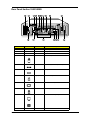
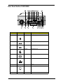
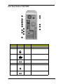
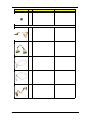
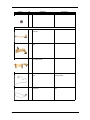
Front Panel-Veriton 3500/3500G
The computer’s front panel consists of the following:
Label
4
Icon
Description
1
Floppy drive light-emitting diode (LED
2
3.5-inch floppy drive
3
Floppy drive eject button
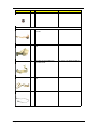
4
CD-ROM/DVD-ROM/CD-RW Headphone/Earphone port
5
Volume control tune
6
CD-ROM/DVD-ROM/CD-RW LED
7
CD-ROM/DVD-ROM/CD-RW tray
8
CD-ROM/DVD-ROM/CD-RW emergency eject hole
9
Stop/Eject button
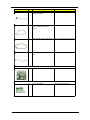
10
USB ports
11
Microphone-in port (front)*
12
Headphone-out port
13
Hard disk drive activity LED
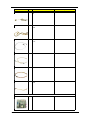
Veriton 3500/5500/7500
Label
Icon
Description
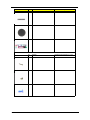
14
LAN Activity LED
15
Power LED
16
Power button
NOTE: *The system has two microphone-in ports (front and rear). However, you cannot use both of them at
the same time. The default setting for your system enables the microphone-in port in front and disables
the one at the back.
Chapter 1
5
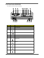
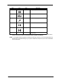
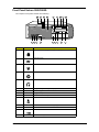
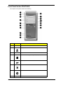
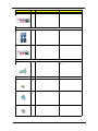
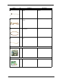
Rear Panel-Veriton 3500/3500G
Label
Icon
Color
1
Power supply
2
Voltage selector switch
3
4
Keyhol
Green
5
PS/2 mouse port
Power Jack (for external speakers)
6
Teal or Turquoise
Serial port
7
Burgundy
Parallel/Printer port
8
Blue
CRT/LCD monitor port*
9
White
Network port
10
Black
Modem line and Telephone port
11
6
Description
Power cord socket
Veriton 3500/5500/7500
Label
Icon
Color
Description
12
Purple
PS/2 keyboard port
13
Black
USB ports
14
Pink
Microphone-in port (rear)**
15
Lime
Audio-out/Line-out jack
16
Light blue
Audio-in/Line-in jack
17
Expansion slots
NOTE: * The CRT monitor port is automatically disabled when an add-on AGP VGA card is installed into the
system. Connect the monitor to the VGA port instead. (Available for S88M/ G)
NOTE: ** The system has two microphone-in ports (front and rear). However, you can not use both of them at
the same time. The default setting for your system enables the microphone-in port in front and disables
the one at the back.
Chapter 1
7
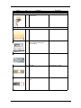
Front Panel-Veriron 5500/5500G
The computer’s front panel consists of the following:
Label
8
Icon
Description
1
Hard disk drive activity light-emitting diode (LED)
2
LAN activity LED
3
Power LED
4
Power button
5
CD-ROM/DVD-ROM Headphone/Earphone port
6
Floppy drive light-emitting diode (LED)
7
3.5-inch floppy disk drive
8
Floppy drive eject button
9
CD-ROM/DVD-ROM tray
10
Stop/Eject button
11
CD-ROM/DVD-ROM/CD-RW emergency eject hole
12
CD-ROM/DVD-ROM LED
13
Volume control tune
14
5.25 drive inch bay
Veriton 3500/5500/7500
Label
Icon
Description
15
Headphone/ earphone port
16
Microphone-in port (front)*
17
USB ports
18
USB ports
NOTE: * The system has two microphone-in ports (front and rear). However, you can not use both of them at
the same time. The default setting for your system enables the microphone-in port in front and disables
the one at the back.
Chapter 1
9
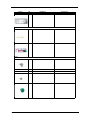
Rear Panel-Veriton 5500/5500G
Label
Icon
Color
1
2
Green
3
PS/2 mouse port
Power jack (for external speakers)
4
Teal or Turquoise Serial port
5
Burgundy
Parallel/printer port
6
Blue
monitor port*
7
White
Network port
8
9
10
10
escription
Voltage selector switch
Keyhol
Black
Modem line port
Expansion slots
Veriton 3500/5500/7500
Label
Icon
Color
escription
11
Black
Telephone line port
12
Light blue
Audio-in/Line-in jack
13
Lime
Audio-out/Line-out jack
14
Pink
Microphone-in port (rear)**
15
Black
USB ports
16
Purple
PS/2 keyboard port
17
Power cord socket
18
Power supply
NOTE: * The CRT monitor port is automatically disabled when an add-on AGP VGA card is installed into the
system. Connect the monitor to the VGA port instead. (Available for S88M/ G)
NOTE: ** The system has two microphone-in ports (front and rear). However, you can not use both of them at
the same time. The default setting for your system enables the microphone-in port in front and disables
the one at the back.
Chapter 1
11
Front Panel-Veriton 7500/7500G
The computer’s front panel consists of the following:
Label
12
Icon
Description
1
CD-ROM/DVD-ROM tray
2
Stop/Eject Butto
3
Skip/Forward Button
4
Hard disk drive activity light-emitting diode (LED)
5
LAN activity LE
6
Power LED
7
Power button
8
CD-ROM/DVD-ROM/CD-RW LED
Veriton 3500/5500/7500
Label
Icon
Description
9
Volume Control Tuner
10
Headphone/earphone port
11
5.25-inch drive bays
12
3.5-inch floppy disk drive
13
Floppy drive LED
14
Floppy drive eject button
15
Speaker-out/Line-out port
16
Microphone-in port (front)*
17
USB ports
NOTE: * The system has two microphone-in ports (front and rear). However, you can not use both of them at
the same time. The default setting for your system enables the microphone-in port in front and disables
the one at the back.
Chapter 1
13
Rear Panel-Veriton 7500/7500G
Label
Icon
Color
1
2
Power cord socket
3
Burgundy
Parallel/printer port
4
White
Network port
5
Power jack (for external speakers)
6
14
Description
Voltage Selector Switch
Power supply
7
Green
PS/2 mouse port
8
Purple
PS/2 keyboard port
Veriton 3500/5500/7500
Label
Icon
Color
Description
9
Black
10
Teal or Turquoise Serial port
11
USB ports
CRT/LCD monitor port*
12
Pink
Microphone-in port (rear)**
13
Lime
Audio-out/Line-out jack
14
Light blue
Audio-in/Line-in jack
15
Black
Telephone port (optional)
16
Black
Modem line port
17
Expansion Slots
NOTE: * The CRT monitor port is automatically disabled when an add-on AGP VGA card is installed into the
system. Connect the monitor to the VGA port instead. (Available for S88M/ G)
NOTE: * *The system has two microphone-in ports (front and rear). However, you can not use both of them at
the same time. The default setting for your system enables the microphone-in port in front and disables
the one at the back.
Chapter 1
15
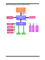
System Block Diagram (Veriton 3500/ 5500/ 7500)
Willamette/
Northwood
Processor
Scaleable Bus
3.2GB/s
VGA
Brookdale-GL
GMCH
266MB/s
8-Bit Hub Interface
SIO
PCI Slot
LAN Connect
PCI Slot
PCI Slot
2 ATA 100 IDE
Channels
16
2.12GB/s
ICH4
6 USB 2.0
ports
AC97’ Audio
CODEC
DDR-266/200
200
DDR-266/
FWH
Veriton 3500/5500/7500
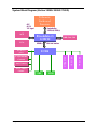
System Block Diagram (Veriton 3500G/ 5500G/ 7500G)
AGP
4X/ 2X
1.5V signal
AGP
VGA
Willamette/
Northwood
Processor
Scaleable Bus
3.2GB/s (4.25GB/s)
Brookdale-G
GMCH
266MB/s
8-Bit Hub Interface
SIO
PCI Slot
LAN Connect
PCI Slot
PCI Slot
2 ATA 100 IDE
Channels
Chapter 1
2.12GB/s
ICH4
6 USB 2.0
ports
AC97’ Audio
CODEC
DDR-266/200
200
DDR-266/
FWH
17
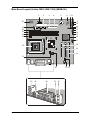
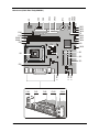
Main Board Layout (Veriton 3500/ 5500/ 7500) (S88M/ GL)
1
3
2
4
5
6
7 8
38
9
10
11
12
13
37
36
35
14
15
34
33
16
18
17
19
32
20
21
31
25
30
18
29
28
27
23 22
26
Veriton 3500/5500/7500
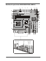
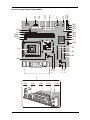
Main Board Layout (Veriton 3500G/5500G/7500G) (S88M/ G)
1
3
2
4
5
6
7 8
38
9
10
11
12
13
37
36
35
14
15
34
33
16
18
17
19
32
20
21
31
25 24
30
Chapter 1
29
28
27
23 22
26
19
Label
Component
1
Game Port
2
Label
20
Component
PCI Slot 2
FDD Connector
21
PCI Slot 3
3
IDE 2 Connector
22
CD-in Connecto
4
IDE 1 Connector
23
Audio for Daughter Board
5
Battery
24
AGP Slot***(for Brookdale G only)
6
FWH
25
Power Connector (+12V
7
Serial IRQ
26
Line-in (upper), Line-out(middle), Mic-in
(lower)
8
Power LED
27
Network (upper) and USB (lower) Ports
9
Power Button
28
Parallel port (upper) and Serial Ports (lower)
10
Audio FPIO Connector
29
Serial Ports
11
LAN Activity LED
30
PS2 Keyboard
12
1-2: Normal*
31
3-pin Fan SYS Connector
2-3: Clear CMOS
13
HDD LED Connector
32
CPU Socket
14
Intrusion Connector
33
3-pin Fan CPU Connector
15
Suspend Power LED
34
Memory Slot 1
16
Intel ICH4 Chipset
35
Memory Slot 2
17
Front USB Connector
36
Power Connector
18
Intel 845GL/G**
37
COM
19
PCI Slot 1
38
SMSC LPC47M192
NOTE: *: default setting
NOTE: **: Intel 845 GL (Veriton 3500/ 5500/ 7500); Intel 845G (Veriton 3500G/ 5500G/ 7500G)
NOTE: ***: not for Brookdale-GL
20
Veriton 3500/5500/7500
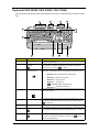
Keyboard (3500/ 3500G, 5500/ 5500G, 7500/ 7500G)
The keyboard has full-sized keys that include separate cursor keys, two Windows keys, and twelve function
keys.
Icon
Component
Description
1
Function keys
Access most of the computer's controls like screen brightness, volume
output and the BIOS utility.
2
Caps lock
When activated, all alphabetic characters typed appear in uppercase
@
(same function as pressing
Windows logo key
Start button. Combinations with this key perform special functions, such
as:
3
•
j + <letter>).
Windows + Tab: Activates the next Taskbar button
•
Windows + E: Explore My Computer
•
Windows + F: Find Document
•
Windows +
•
j + Windows + M: Undo Minimize All
•
Windows + R: Displays Run dialog box
: Minimize All
4
Application key
Opens the applications context menu (same function as clicking the right
button of the mouse).
5
Cursor keys
Also called arrow keys, let you move the cursor around the screen. They
serve the same function as the arrow keys on the numeric pad when the
] is toggled off.
6
Palm rest
7
Num Lock Key
]
8
Chapter 1
When activated, the keypad is set to numeric mode, i.e., the keys function
as a calculator (complete with arithmetic operators such as +, -, * and /).
Scroll Lock Key
When activated, the screen moves one line up or down when you press
[
the up arrow or down arrow respectively. Take note that
work with some applications.
[may not
21
Icon
Component
Description
9
Volume control/Mute
knob
Controls the speaker volume. Turn it clockwise or counterclockwise to
adjust the volume. Press it to toggle between mute and sound.
10
Multimedia keys
Allow you to do the following:
11
Internet/Suspend keys
•
Play/Pause button
: press to start playing the audio
track or video file. Press again to pause.
•
Stop Button
video file.
•
: press to skip forward to the next track
Forward Button
or file and start playing.
•
Backward button
: press to skip backward to the previous track or file and start playing.
Consist of three buttons:
•
Email
: launches the email application that came bundled with your system.
•
Web brows :
er launches the browser application that
came bundled with your system.
•
12
22
Programmable keys
: press to stop playing the audio track or
Suspen :
button.
d puts the system to sleep when pressed this
Help you directly access a URL (Web site) or launch any programs, files,
or applications in your system. The fifth key is set to launch the Windows
media player. To configure the settings of each key, right click on the Magic
Keyboard icon located on your desktop.
Veriton 3500/5500/7500
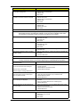
Hardware Specifications and Configurations
Processor
Item
Specification
Type
Intel® Pentium IV FC-PGA2 processors with mPGA478 package
Slot
Socket mPGA478
Speed
Internal: 1.4~2.4GHz+
External: 400/533MHz Data Bus Frequency for Brookdale-G and 400 MHz for
Brookdale-GL.
Minimum operating speed
0 MHz (If Stop CPU Clock in Sleep State the BIOS Setup is set to Enabled.)
Voltage
Processor voltage can be detected by the system without setting any jumper.
BIOS
Item
Specification
BIOS code programmer
Award
BIOS version
V6.0
BIOS ROM type
Intel FWH SST 49LF004-33-4C-NH
BIOS ROM size
4MB
Support protocol
PCI 2.1, APM1.2, DMI 2.00.1, E-IDE, ACPI 1.0, ESCD 1.03, ANSI ATA 3.0, PnP
1a, Bootable CD-ROM 1.0, ATAPI
Boot from CD-ROM feature
Yes
Support to LS-120 drive
No
Support to BIOS boot block feature Yes
NOTE: The BIOS can be overwritten/upgraded using the FLASH utility (AWDFLASH.EXE).
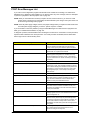
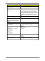
BIOS Hotkey List
Hotkey
Function
Description
c
Enter BIOS Setup Utility
Press while the system is booting to enter BIOS
Setup Utility.
a+ o
Enable hidden page of BIOS Setup Utility
Press in BIOS Setup Utility main menu screen,
the Advanced Options menu then appears.
The items on the Advanced Options menu are:
Memory/Cache Options
PnP/PCI Options
Chips Options
Chapter 1
23
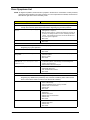
This section has two table lists, system memory specification and the possible combinations of memory
module.
System Memory
Item
Specification
Memory socket numbe
2 sockets (4 rows)
Support memory size per socket
64/128/256/512MB
Support maximum memory size
2GB
Support memory type
DDR DRAM PC1600/2100
Support memory speed
DDR 266/ DDR 20
Support memory voltage
2.5V
Support memory module package
184 -pin DIMM
Support to parity check feature
Yes
Support to Error Correction Code (ECC
feature.
Yes
Memory module combinations
You can install memory modules in any combination as long as they match
the Memory Combination specifications.
Memory Combinations
DIMM 1
DIMM 2
TOTAL
X*
Y*
2GB
0M
64M
64M
0M
128M
128M
0M
256M
256M
0M
512M
512M
64M
0M
64M
128M
0M
128M
256M
0M
256M
512M
0M
512M
64M
64M
128M
128M
64M
192M
256M
64M
320M
512M
64M
576M
64M
128M
192M
128M
128M
256M
256M
128M
384M
512M
128M
640M
64M
256M
320M
128M
256M
384M
256M
256M
512M
512M
256M
768M
64M
512M
576M
128M
512M
640M
256M
512M
768M
512M
512M
1024M
*X, Y, Z: 0~2GB
24
Veriton 3500/5500/7500
Cache Memory
Item
Specification
First-Level Cache Configurations
Cache function control
Enable/Disable by BIOS Setup (Advanced options)
Second-Level Cache Configurations: Below information is only applicable to system with installed Pentium 4 processor.
L2 Cache RAM size
Pentium IV processor: 512 KB for Northwood and 256KB for Willamette
L2 Cache RAM speed
The same with the processor core clock frequency
L2 Cache function control
Enable/Disable by BIOS Setup
Video Interface
Item
Specification
Video controller resident bus
AGP bus
Video interface support
1x / 2x / 4x AGP Data Transfer and 2x / 4x Fast Write Capability
The AGP buffers operate only 1.5V mod
NOTE: S88M/ GL for Veriton 3500/ 5500/ 7500 doesn’t have AGP VGA slot.
Chapter 1
25
Audio Interface
Item
Specification
Audio controller
Embedded in Intel 82801DB ICH 4
Audio controller resident bus
AC’97 link
Audio function control
Enable/disable by BIOS Setup
Mono or stere
Stereo
Resolution
20 bits
Compatibility
AC’97 2.1 compliant
Sound Blaster Pro compatible
Mixed digital and analog high performance chip
Enhanced stereo full duplex operation
High performance PCI audio accelerator
High-Quality ESFM music synthesize
MPU-401(UART mode) interface for wavetable synthesizers and MIDI devices
Integrated game port
Meets PC 97/PC98 and WHQL specifications
Music synthesizer
Yes
Sampling rate
44.1 KHz
MPU-401 UART support
Yes
Microphone jack
Supported On audio-I/O board (Front Panel Access)
Headphone jack
Supported On audio-I/O board (Front Panel Access)
Package
QFP64
Line-in/Line-out/speaker-out
Supported On audio-I/O board (connects via CN14)
IDE Interface
Item
Specification
IDE controller
Embedded in Intel 82801DB ICH 4
IDE controller resident bus
PCI bus
Number of IDE channel
2 on-board: 40-pin hard disk drive connector,
Support IDE interface
E-IDE (up to PIO mode 4 and Ultra DMA/33, Ultra DMA/66 and Ultra DMA/100)
ANSIS ATA rev3.0/ ATAPI specification
Support bootable CD-ROM
Yes
Floppy disk drive Interface
Item
Vendor & Model Name
Specification
Panasonic JU-256A047P
Floppy Disk Specifications
Media Recognition
26
1.44 MB
Cylinders
80
Tracks
160
Rotational speed (RPM)
300
Read/write heads
2
Encoding method
MFM/FM
Power requirement (max)
5V
Startup (peak
290mA
Maximum Seeking (RMS)
710mA
Voltage tolerance (V
+5V +/- 10%
Veriton 3500/5500/7500
Floppy disk drive Interface
MTBF (Mean Time Between Failure)
30,000
Floppy disk drive controller
Embedded in SMSC LPC47M192
Floppy disk drive controller resident bus
LPC
Support FDD format
360KB, 720KB, 1.2MB, 1.44MB, 2.88MB; 3-mode
Hard Disk Drive Interface
Item
Specification
Vendor & Model Name
Seagate U Series 40810 ST340810A
Capacit
40GB
Bytes per sector
512
Average seek time (ms)
8.9
Data Heads
2
Drive Format
Disks
1
Spindle speed (RPM
5400
Performance specifications
Buffer size (Kbyte)
512
Cache buffer
2
Interface
Altra ATA/ 100
Internal data transfer rate
436
(Mbytes/s) max.
I/O Data transfer rate
100 MB/sec.
(Mbytes/s) max.
Ultra ATA Mod
ATA data transfer modes supported
PIO Modes 0-4
Multiword DMA Modes 0-2
Ultra DMA Modes
DC Power Requirements (max)
5V
12V
Startup (peak
1.5A
2A
Maximum seeking (RMS)
1.5A
2A
Voltage tolerance
5V(DC) +/- 5%
12V(DC) +/- 10
MTBF (Mean Time Between Failure)
625,000
S.M.A.R.T. function
supported
DVD-ROM Interface
Item
Specification
Vendor & Model Name
Pioneer DVD-117RD
Performance Specification
With CD Diskette
With DVD Diskette
Transfer rate (KB/sec)
Sustained:
Sustained:
Max 3.6 MB/s
Max8.31MB/s
Average access time
120ms
180m
Data Buffer Capacity
512 KBytes
Interface
IDE/ATAPI
Applicable disc format
DVD-ROM(DVD-5, DVD-9, DVD-10, DVD-17), DVD-R, CD-ROM (mode 1 an
mode 2), CD-ROM XA (mode 2, Form 1 and Form 2), Photo-CD (single and
multiple sessions), CD Extra, CD-I FMV, Video CD, CD Text, CD-R/W and CDDA disc format
loading mechanism
Soft eject (with emergency eject hole)
Chapter 1
27
DVD-ROM Interface
Item
Power Requirement
Specification
+5V
+12V
Voltage tolerance
+/-5%
+/-5%
Standby (Sleep)
150mA
2mA
Avtiv
500mA
1.2A
CD-R/W Interface
Item
Vendor & Model Name
Transfer rate (KB/sec)
Specification
AOpen CRW3248
Sustained:
Max 6000 KB/sec
Average access time
100ms
Data Buffer Capacity
8MB/ 2MB
Interface
E-IDE/ATAPI
Applicable disc format
CD-ROM (mode 1 and mode 2), CD-ROM XA (mode 2, Form 1 and Form 2),
Photo-CD (single and multiple sessions), CD Extra, CD-I FMV, Video CD, CD
Text, CD-R/W and CD-DA disc format.
loading mechanism
Soft eject (with emergency eject hole), eject button must be upside
Power Requirement
+5V
+12V
Voltage tolerance
+/-10%
+/-10%
Standby (Sleep)
20mA
2mA
Avtiv
1.5A max.
1A max.
Parallel Port
Item
Specification
Parallel port controller
Embedded in SMSC LPC47M192
Parallel port controller resident bus
LPC
Number of parallel ports
1
Support SPP,ECP, EPP
SPP/ECP / EPP 1.7 & 1.9
Connector type
25-pin D-type female connector
Parallel port function control
Enable/disable by BIOS Setup
Optional ECP DMA channel
(in BIOS Setup)
DMA channel 1
DMA channel 3
Optional parallel port I/O address
(via BIOS Setup)
378-37F
278-27F
778-77A
Optional parallel port IRQ
(via BIOS Setup)
IRQ5
IRQ7
Serial Port
Item
28
Specification
Serial port controlle
Embedded in SMSC LPC47M192
Serial port controller resident bus
LPC
Number of serial port
2
Serial ports location
COM1, COM 2(Reserve for header)
16C550 UART support
Yes
Connector type
15-pin connector (1 with pin reserve)
Veriton 3500/5500/7500
Serial Port
Optional serial port I/O address
(via BIOS Setup)
2F8-2FF
Optional serial port IRQ
(via BIOS Setup)
4, 3
3F8-3FF
Modem
Item
Specification
Fax modem data baud rate (bps)
14.4K bps
Data modem data baud rate (bps)
56K bps
Voice modem
Yes
Modem connector type
RJ11
Full duplex
Yes
USB Port
Items
Universal UHCI
Specifications
USB 1.1
Universal EHCI
USB 2.0
USB Clas
Support legacy keyboard for legacy mode
Chapter 1
29
Memory Address Map
Address
Size
Function
000000 - 07FFFF
512KByte
Host Memory
080000 - 09FFFF
128KByte
Host/PCI Memory
0A0000 - 0BFFFF
128KByte
PCI/ISA Video Buffer Memory
0C0000 - 0C7FFF
32KByte
Video BIOS Memory
0C8000 - 0DFFFF
96KByte
ISA Card BIOS & Buffer Memory
0E0000 - 0EFFFF
64KByte
BIOS Extension Memory
Setup and Post Memory
PCI Development BIOS
0F0000 - 0FFFFF
64KByte
System BIOS Memory
100000 - UPPER LIMIT
Main Memory
UPPER LIMIT - 4GBytes
PCI Memory
Note : UPPER LIMIT means the maximum size of installed memory.
The Main Memory Maximum size are 768M Bytes.
Onboard Device ID & IRQ Map
Device
AD#
IDSEL
Intel 845G MCH
AD11
00h
P2P
AD30
13h
(Func.0) ICH4 (LPC)
AD31
14h
(Func.1) ICH4 (IDE)
AD31
14h
(Func.2) ICH4(USB)
AD31
14h
(Func.3) ICH4 (SMBUS
AD31
14h
(Func.5) ICH4 (AC97 Audio)
AD31
PCI Slot 1
AD16
PCI Slot 2
PCI Slot 3
Route Reg.
Mask
68h
FFh
14h
61h
FFh
05h
60h
FFh
AD17
06h
61h
FFh
AD21
07h
62h
FFh
PCI Slot IRQ Routing Map
PCI INTX#
30
INT
INTB
INTC
INTD
PCI 1
Route 1
Route 2
Route 3
Route 4
PCI 2
Route 4
Route 1
Route 2
Route 3
PCI 3
Route 3
Route 4
Route 1
Route 2
Veriton 3500/5500/7500
I/O Address Map
Hex Range
Devices
000-00F
DMA Controller-1
020-021
Interrupt Controller-1
040-043
System Timer
060-060
Keyboard Controller 8742
061-061
System Speaker
070-071
CMOS RAM Address and Real Time Clock
081-08F
DMA Controller-2
0A0-0A1
Interrupt Controller-2
0C0-0DF
DMA Controller-2
0F0-0FF
Math Co-Processor
170-177
Secondary IDE
1F0-1F7
Primary IDE
278-27F
Parallel Printer Port 2
2F8-2FF
Serial Asynchronous Port 2
378-37F
Parallel Printer Port 1
3F0-3F5
Floppy Disk Controller
3F6-3F6
Secondary IDE
3F7-3F7
Primary IDE
3F8-3FF
Serial Asynchronous Port 1
0CF8
Configuration Address Register
0CFC
Configuration Data Registe
778-77A
Parallel Printer Port 1
IRQx Assignment Map
IRQx
System Devices
Add-On-Card Devices
IRQ0
Timer
N (Notes)
IRQ1
Keyboard
N
IRQ2
Cascade Interrupt Control
N
IRQ3
Serial Alternate
Reserved
IRQ4
Serial Primary
Reserved
IRQ5
Parallel Port (Alternate)
Reserved
IRQ6
Floppy Diskette
Reserved
IRQ7
Parallel Port
Reserved
IRQ8
Real Time Clock
N
IRQ9
N
Reserved
IRQ10
N
Reserved
IRQ11
N
Reserved
IRQ12
PS/2 Mouse
Reserved
IRQ13
Math Co-processor Exception
N
IRQ14
Fix Diskette
Reserved
IRQ15
Fix Diskette
Reserved
NOTE: N - Not be used.
Chapter 1
31
DRQx Assignment Map
DRQx
System Devices
Add-On-Card Devices
DRQ0
N (Notes)
Reserved
DRQ1
N
Reserved
DRQ2
Floppy Diskette
N
DRQ3
N
Reserved
DRQ4
Cascade
N
DRQ5
N
Reserved
DRQ6
N
Reserved
DRQ7
N
Reserved
NOTE: N - Not to be used.
Main Board Major Chips
Item
Controller
North Bridge
Intel BROOKDALE-G/GL
South Bridge
Intel 82801DB ICH 4
Super I/O controller
SMSC LPC47M192-NC
Audio Codec
STAC9750 Sigmatel
LAN controlle
Intel 82562ET
HDD controller
Built-in Intel 82801DB ICH 4
Keyboard controller
Built-in Intel 82801DB ICH 4
RTC
Built-in Intel 82801DB ICH 4
Environmental Requirements
Item
Specifications
Temperature
Operating
+10 to +35°C
Non-operating
-10 to +60°C
Non-operating
-20 to +60°C (Storage package)
Humidity
Operating
20% to 80% RH, non-condensing
Non-operating
20% to 80% RH, non-condensing (Unpacked
Non-operating
20% to 80% RH, non-condensing (Storage package)
Vibration
Operating:
Sweep rate:
Direction:
Test cycles:
Non-operating:
(Packed)
Sweep rate:
Direction:
Test cycles:
32
5~16.2 Hz
16.2~250 Hz
0.38mm (peak to peak)
0.2G
1 octave/minute
X, Y, Z axis
2 cycles per axis
5~27.1 Hz
27.1~50 Hz
50~500 Hz
0.5 coactive/minut
X, Y, Z axis
4 cycles per axis
0.6G
0.4mm (peak to peak
2.0G
Veriton 3500/5500/7500
Mechanical Specifications
Item
Specification
Dimensions
244(L)X 244(W)x18mm(H)
Weight
One 3.5 FDD and one 3.5 HDD
Depends on local configuration
(without packing
Switching Power Supply
A-1 Input frequency
Normal Frequenc
Frequency Variation Range
50Hz
47Hz to 53Hz
60Hz
57Hz to 63Hz
A-2 Input voltage
Nominal Voltage
Variation Range
100 - 120 VRMS
90-132 VRMS
200 - 240 VRMS
180-264 VRMS
A-3 Input current
Input Current
Measuring Range
4A
90 -132 VRMS
3A
180 - 264 VRMS
(This is 145W power supply)
!
This “4A” includes the outlet supply current: 2A
!
Measure at line input 90 VRMS and maximum load condition.
Output Requirements
Regulation
Current Rating (Max)
+5V
+5%
8A
+12V
+5%
10A
-12V
+10
0.3A
+3.3V
+5%
10A
+5Vaux
+5%
3A
NOTE: 1. +5V & +3.3V total power is 80W max .
Chapter 1
33
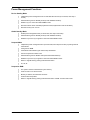
Power Management Functions
Device Standby Mode
!
Independent power management timer for hard disk drive devices (0-15 minutes, time step=1
minute).
!
Hard disk drive goes into Standby mode (for ATA standard interface).
!
Disable V-sync to control the VESA DPMS monitor.
!
Resume method: device activated (Keyboard for DOS, keyboard & mouse for Windows).
!
Resume recovery time: 3-5 sec.
Global Standby Mode
!
Global power management timer (2-120 minutes, time step=10 minutes).
!
Hard disk drive goes into Standby mode (for ATA standard interface).
!
Disable H-sync and V-sync signals to control the VESA DPMS monitor.
Suspend Mode
!
Independent power management timer (2-120 minutes, time step=10 minutes) or pushing external
switch button
!
CPU goes into SMM.
!
CPU asserts STPCLK# and goes into the Stop Grant State.
!
LED on the panel turns amber color.
!
Hard disk drive goes into SLEEP mode (for ATA standard interface).
!
Disable H-sync and V-sync signals to control the VESA DPMS monitor.
!
Return to original state by pushing external switch button.
!
S1, S3, S4
Suspend to RAM
34
!
The system context is maintained in system memory
!
Power is shut to non-critical circuits.
!
Memory is retained, and refreshes continues.
!
All clocks shut except RTC.
!
Return to original state by pushing external switch button & “PME” events at ACPI mode.
Veriton 3500/5500/7500
Chapter 2
System Utilities
Most systems are already configured by the manufacturer or the dealer. There is no need to run
Setup when starting the computer unless you get a Run Setup message.
The Setup program loads configuration values into the battery-backed nonvolatile memory called CMOS RAM.
This memory area is not part of the system RAM.
NOTE: If you repeatedly receive Run Setup messages, the battery may be bad. In this case, the system cannot
retain configuration values in CMOS.
Before you run Setup, make sure that you have saved all open files. The system reboots immediately after you
exit Setup.
Chapter 2
36
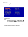
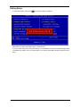
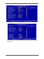
Entering Setup
To enter Setup, press the key c during the POST (Power-on self-test).
NOTE: You must press c simultaneously while the system is booting.
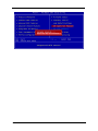
The Setup Utility main menu then appears:
The above screen is the BIOS Utility Basic Level screen. It allows you to view and change only the basic
configuration of your system.
The command line at the bottom of the menu tells you how to move within a screen and from one screen to
another.
!
!
To select an option, move the highlight bar by pressing
To change a parameter setting, press { or }until the desired setting is found, or press
e
!
w, y , z, or x ,then press e
to pop out the screen with available items for selection.
Press^ to return to the main menu. If you are already in the main menu, press ^ again to
exit Setup.
The parameters on the screens show default values. These values may not be the same as those in your
system.
The grayed items on the screens have fixed settings and are not user-configurable.
37
Veriton 3500/5500/7500
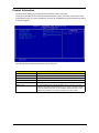
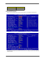
Product Information
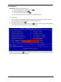
The screen below appears if you select Product Information from the main menu:
The Product Information menu contains general data about the system, such as the product name, serial
number, BIOS version, etc. These information is necessary for troubleshooting (maybe required when asking
for technical support).
The following table describes the parameters found in this menu:
Parameter
Description
Product Name
Displays the model name of your system.
System S/N
Displays your system’s serial number.
Main Board ID
Displays the main board’s identification number.
Main Board S/N
Displays your main board’s serial number.
System BIOS Version
Specifies the main version of your BIOS utility.
SMBIOS version
The System Management Interface (SM) BIOS allows you to check your syste
hardware components without actually opening your system. Hardware checking
is done via software during start up. This parameter specifies the version of the
SMBIOS utility installed in your system. The BIOS Version here is V2.3.
Chapter 2
38
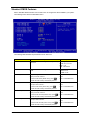
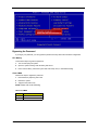
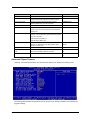
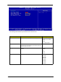
Standard CMOS Features
Select “Standard CMOS Features” from the main menu to configure the drives installed in your system.
The following screen shows the Disk Drives menu:
The following table describes the parameters found in this menu.
Parameter
Date
Description
Options
Lets you set the date following the weekday-month-day- Weekday: Sun, Mon....Sat
year format
Month: Jan, Feb...Dec
Day: 1 to 31
Year 1980 to 2079
Time
Lets you set the time following the hour-minute-second
format
Hour: 0 to 23
Minute: 0 to 59
Second: 0 to 59
IDE Primary Master
Lets you configure the hard disk drive connected to the
master port of IDE channel 1.
To enter the IDE Primary Master setup, press
e.
(Show the Status:)
None
HDD or CD-ROM Number
The IDE CD-ROM is always automatically detected.
IDE Primary Slave
Lets you configure the hard disk drive connected to the
slave port of IDE channel 1.
To enter the IDE Primary Slave setup, press
e.
(Show the Status:)
None
HDD or CD-ROM Number
The IDE CD-ROM is always automatically detected.
IDE Secondary Master
Lets you configure the hard disk drive connected to the
master port of IDE channel 2.
To enter the IDE Secondary Master setup, press
e.
(Show the Status:)
None
HDD or CD-ROM Number
The IDE CD-ROM is always automatically detected.
IDE Secondary Slave
Lets you configure the hard disk drive connected to the
slave port of IDE channel 2.
To enter the IDE Secondary Slave setup, press
e.
(Show the Status:)
None
HDD or CD-ROM Number
The IDE CD-ROM is always automatically detected.
39
Veriton 3500/5500/7500
Parameter
Drive A
Description
Allows you to configure your floppy drive A.
Options
1.44 MB, 3.5-inch
None
360 KB, 5.25-inch
1.2 MB, 5.25-inch
720 KB, 3.5-inch
2.88 MB, 3.5-inch
Drive B
Allows you to configure your floppy drive B.
None
360 KB, 5.25-inch
1.2 MB, 5.25-inch
720 KB, 3.5-inch
1.44 MB, 3.5-inch
2.88 MB, 3.5-inch
Video
Halt On
This item specifies the type of video card in use. The
default setting is VGA/EGA. Since current PCs use
VGA only, this function is almost useless and may be
disregarded in the future.
EGA/VGA
This parameter enables you to control the system stops
in case of Power-on self-test (POST) errors.
All, But Keyboard
CGA40
CGA80
Mono
All Errors
No Error
All, But Diskette
All, But Disk/Key
Base Memory
Refers to the portion of memory that is available to
standard DOS programs. DOS systems have an
address space of 1 MB, but the top 384 KB (called high
memory) is reserved for system use. This leaves 640
KB of conventional memory. Everything above 1 MB is
either extended or expanded memory.
Extended Memory
Memory above and beyond the standard 1 MB
(megabyte) of base memory that DOS supports.
Extended memory is only available in PCs with an Intel
80286 or later microprocessor. Extended memory is not
configured in any special manner and is therefore
unavailable to most DOS programs. However, MS
Windows and OS/2 can use extended memory.
Total Memory
Total base, and extended memory, and I/O ROM 384KB
available to the system.
Chapter 2
40
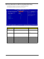
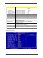
IDE Primary Master/Slave and IDE Secondary Master/Slave Setup
The following screen appears if you select any of the IDE drive parameters:
The following table describes the parameters found in this menu.
Parameter
Description
Options
IDE HDD AutoDetection
Auto-detects your hard disk drive.
Press Enter
IDE Primary Master
Displays the device type
Auto
None
Manual
Access Mode
Selects the HDD access mode
Auto
Large
LBA
CHS
41
Capacit
Shows the size of your hard disk in MB.
xxxxx MB
Cylinder
Shows your hard disk’s number of cylinders.
0 to 65535
Head
Shows your hard disk’s number of heads
0 to 255
Precomp
Selects the Precomp number for old HDD parking
0 to 65535
Landing Zone
Selects the Landing Zone number for old HDD parking
0 to 65535
Sector
Shows your hard disk’s number of sectors
0 to 255
Veriton 3500/5500/7500
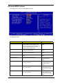
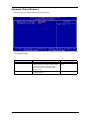
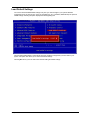
Advanced BIOS Features
The following screen shows the Advanced BIOS Features.
The following table describes each Advanced BIOS Features parameter. Settings in boldface are the default
and suggested settings.
Parameter
Virus Warning
Description
Options
Allows you to choose the Virus warning feature fo
the IDE hard disk boot sector protection. If this
function is enabled and someone attempts to write
data into this area, BIOS will show a warning
message on screen and alarm beep.
Disabled
Quick Power On Self Test
This parameter speeds up POST by skipping some
items that are normally checked.
Enabled
Silent Boot
This item is used to decide if the system logo
displays when the system boots up.
Enabled
Configuration Table
Displays preboot system configuration table when
enabled.
Disabled
Hard Disk Boot Priority
Select Hard Disk Boot Device Priority
Press Enter
Enabled
Disabled
Disabled
Enabled
Show Hard Disk Name
1/2/3/4/5
First Boot Device
This parameter allows you to specify the syste
boot up search sequence.
Second Boot Device
This parameter allows you to specify the syste
boot up search sequence.
CD-ROM, Floppy, LS120, Hard
Disk, ZIP100, LAN (on board
LAN-- Boot from LAN),
Disabled
Flopp , LS120, Hard Disk,
CD-ROM, ZIP100, LAN (on
board LAN-- Boot from LAN),
Disabled
Third Boot Device
This parameter allows you to specify the syste
boot up search sequence.
Hard Disk, Floppy, LS120,
CD-ROM, ZIP100, LAN (on
board LAN-- Boot from LAN),
Disabled
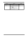
Chapter 2
42
Parameter
Boot Other Device
Security Option
Description
Options
This parameter allows you to specify the syste
boot up search sequence.
Enabled
The Setup option limits access only to BIOS setup.
To disable the security option, select Password
Setting from the main menu, don’t type anything
Setup
Disabled
System
and just press e.
The System option limits access to both the
System boot and BIOS setup. A prompt asking you
to enter your password appears on the screen
every time you boot the system.
43
Veriton 3500/5500/7500
Advanced Chipset Features
The following screen shows the Advanced Chipset Features.
The following table describes each Advanced Chipset Features parameter. Settings in boldface are the default
and suggested settings.
Parameter
Memory Hole at 15M-16
AGP Aperture Size (MB)
Chapter 2
Description
Options
This option lets you reserve system memory area
for special ISA cards. The chipset accesses code/
data of these areas from the ISA bus directly.
Normally, these areas are reserved for memory
mapped I/O cards.
Disabled
This item lets you determine the effective size of the
AGP Graphic Aperture.
64, 4, 8, 16, 32, 128 and 256
Enabled
44
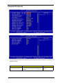
Integrated Peripherals
The following table describes each Integrated Peripherals parameter. Settings in boldface are the default and
suggested settings.
Parameter
On-Chip Primary PCI IDE
On-Chip Secondary PCI IDE
45
Description
These parameters let you enable or disable the IDE
devices connected to the primary and secondary IDE
connectors.
Options
Enabled
Disabled
Veriton 3500/5500/7500
Parameter
IDE Primary Master PIO
IDE Primary Slave PIO
IDE Secondary Master PIO
IDE Secondary Slave PIO
Description
Setting these items to Auto activates the HDD speed
auto-detect function. The PIO mode specifies the data
transfer rate of the HDD. For example, mode 0 data
transfer rate is 3.3 MB/s, mode 1 is 5.2 MB/s, mode 2 is
8.3 MB/s, mode 3 is 11.1 MB/s and mode 4 is 16.6 MB/s.
If your hard disk performance becomes unstable, you
may manually try the slower mode.
Options
Auto
Model 0
Mode 1
Mode 2
Mode 3
Mode 4
Caution: It is recommended that you connect the first
IDE device of each channel to the endmost
connector of the IDE cable.
IDE Primary Master UDMA
IDE Primary Slave UDMA
IDE Secondary Master UDMA
These items allow you to set the Ultra DMA/33/66/100
mode supported by the hard disk drive connected to your
primary and secondary IDE connectors.
Auto
This item is used to enable or disable the On-chip USB.
Enabled
Disabled
IDE Secondary Slave UDMA
USB controller
Disabled
USB Keyboard Support
This item lets you enable or disable the USB keyboard
driver within the onboard BIOS. The keyboard driver
simulates legacy keyboard command and lets you use a
USB keyboard during POST or after boot if you don’t
have a USB driver in the operating system.
Enabled
This item lets you enable or disable the USB mouse
driver within the onboard BIOS. The mouse driver
simulates legacy mouse command and lets you use a
USB mouse during POST or after boot if you don’t have
a USB driver in the operating system.
Enabled
AC97 Audio
Enabling the on-die AC97 Audio if no add-on PCI Audio
device.
Auto
Onboard LAN Controller
ICH4 On-die LAN
Enabled
USB Mouse Support
Disabled
Disabled
Disabled
Disabled
Init Display First
IDE HDD Block Mode
Power on Function
If you installed a PCI VGA card and an AGP card at the
same time, this item lets you decide which one is the
initial display card.
Onboard/ AGP
This feature enhances disk performance by allowing
multisector data transfers and eliminates the interrupt
handling time for each sector. Most IDE drives, except
with old designs, can support this feature.
Enabled
PCI Slot
Disabled
The options to switch on the system.
Button Only
Button only (press the power button only)
Any Key
Any Key (press any key on the PS2 keyboard or press
the power button)
Keyboard 98
Keyboard 98 ( press key on the PS2 keyboard or press
the power button)
Onboard FDC Controller
Onboard Serial Port 1
Setting this parameter to Enabled allows you to connect
your floppy disk drives to the onboard floppy disk
connector instead of a separate controller card. Change
the setting to Disabled if you want to use a separate
controller card.
Enabled
This item allows you to assign an address and interrupt
for the board serial port.
3F8/ IRQ4
Disabled
Auto
2F8/ IRQ3
3E8/ IRQ4
2E8/ IRQ3
Disabled
Chapter 2
46
Parameter
Onboard Serial Port 2
Description
This item allows you to assign an address and interrupt
for the board serial port.
Options
2F8/ IRQ3
Auto
3F8/ IRQ4
3E8/ IRQ4
2E8/ IRQ3
Disabled
Onboard Parallel Port
This item controls the onboard parallel port address an
interrupt.
378/ IRQ7
3BC/ IRQ7
NOTE: If you are using an I/O card with a parallel port, 278/ IRQ5
make sure that the addresses and IRQs do not
have conflict.
Parallel Port Mode
Disabled
IBM PC/AT and PS/2 compatible bi-directional parallel
port. (SPP)
Printer
Enhanced Parallel Port (EPP)-compatible with EPP1.7
and EPP 1.9.
ECP
Extended Capabilities Port (ECP) Specification by
Microsoft and HP.
EPP1.7+SPP
IEEE 1284 compliant
ECP Mode Use DMA
Selects the ECP Mode DMA Channel.
Game Port Address
Selects the Game Port Address.
SPP
EPP1.7+ECP
EPP1.9+SPP
EPP1.9+ECP
3
1
201
209
Disabled
Midi Port Address
Selects the Midi Port Address.
330
300
290
Disabled
Midi Port IRQ
Selects the Midi Port IRQ.
10
5
47
Veriton 3500/5500/7500
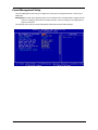
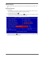
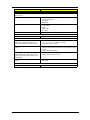
Power Management Setup
The Power Management menu lets you configure the system power-management feature. It works only in
APM mode.
IMPORTANT:If an ACPI-aware operating system such as Windows 98 or Windows 2000 is installed in ACPI
mode, the operating system will use the ACPI interfaces. Then the settings in Power Management
page is non-effective.
The following screen shows the Power Management parameters and their default settings:
Chapter 2
48
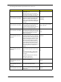
The following table describes the parameters found in this menu.
Parameter
Run VGABIOS if S3 Resume
Power Management
(Function Enabled in APM Mode)
Suspend Mode
(Function Enabled in APM Mode)
HDD Power Down
(Function Enabled in APM Mode)
Soft-Off by PWR-BTTN
(Function Enabled in ACPI and
APM Mode)
PWRON After PWR-Fail
(Function Enabled in ACPI and
APM Mode)
Description
Options
Auto:BIOS decides whether the VGA BIOS
should initiate or not.
Auto
If the default is set to “Yes”, then the VGA
BIOS initiates automatically. If it is set to “No”,
the VGA BIOS will not initiate automatically.
No
This function allows you to set the default
parameters for power-saving modes. Set it to
Disable to turn off the power management
function. Set it to User Define to choose you
own parameters. See the Power Management
Mode Table.
Min Saving
This item lets you set the period of time after
which the system enters into Suspend mode.
The Suspend mode can be Power On
Suspend or Suspend to Hard Drive, and it is
selected in the “Suspend Mode Option”.
Disabled, 1 min., 2 min., 4 min.,
8 min., 12 min., 20 min., 30 min.,
40 min., and 1 Hou
This option lets you specify the IDE HDD idle
time before the device enters the power down
state. This item is independent from the power
states previously described in this section
(Standby and Suspend).
Disabled
Yes
User Define
Max Saving
1 min
15 min
This is a specification of ACPI and supported
Delay 4 sec.
by hardware. When Delay 4 sec. is selected,
Instant-Off
the soft power switch on the front panel can be
used to control power On, Suspend and Off. If
the switch is pressed less than 4 sec. during
power On, the system will go into Suspend
mode. If the switch is pressed longer than 4
sec, the system will be turned Off. The other
setting is Instant-Off, where the soft power
switch is only used to control On and Off, there
is no need to press 4 sec, and there is no
Suspend.
Use this option to determine the manner by
which the system will power on after a power
failure.
Former-Sts
On
Off
Former Sts (former status) - System would
return to its former running state prior to th
power failure.
On - System would be on full on state upo
resuming from power failure.
Off - System would remain off.
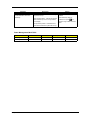
Wake-Up by PCI Card
(Function Enabled in ACPI and
APM Mode)
Power-On by Ring
(Function Enabled in ACPI and
APM Mode)
USB KB Wake-up from S3
(Function Enabled in ACPI mode)
49
Use PCI PME# Wake-Up system . PCI must
meet PCI 2.2 specification.
Enabled
When Enabled, any fax/ modem activity wakes
up the system from suspend mode.
Disabled
When enabled, any USB keyboard activity
wakes up the system from S3 (STR, Suspend
to RAM) mode.
Enabled
Disabled
Enabled
Disabled
Veriton 3500/5500/7500
Parameter
Description
Resume by Alarm
(Function Enabled in ACPI and
APM Mode)
Options
Use this option to set the date and time for you
computer to boot up.
Disabled
Date (of month) Alarm * - Indicate month when
system will boot up. Set it to 0 if you want to
boot everyday.
* Set Resume by Alarm to
Time (hh:mm:ss) Alarm* - Indicate the hour,
minute and second when system will boot up.
Enabled
Enabled, then press e to
show the range of Date and Time
Alarm.
NOTE: In ACPI mode: Valid-S5 and S4. In APM mode: Valid- shutdown
Power Management Mode Table
Mode
Doze
Standby
Suspend
HDD Power Down
Max Saving
1 hou
1 hour
1 hou
15 mi
Min Saving
1 min
1 min
1 min
1 min
Chapter 2
50
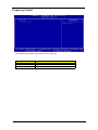
PnP/PCI Configurations
The table below describes each PnP/PCI configuration parameter. Settings in boldface are the default and
suggested settings.
Parameter
Reset Configuration Dat
Resources Controlled By
IRQ Resources
IRQ 3 (COM2)
IRQ 4 (COM1)
IRQ 5 (Network/Sound or
Others
IRQ 7 (Printer or Others)
IRQ 9 (Video or Others)
IRQ 10 (SCSI or Others)
IRQ 11 (SCSI or Others)
Description
Options
Select Enabled to reset Extended System
Configuration Data (ESCD) when you exit Setup
if you have installed a new add-on and the
system configuration has caused such a serious
conflict that the OS cannot boot.
Disabled
Setting this option to Manual allows you to
individually assign the IRQs and DMAs to the
ISA and PCI devices. Set this to Auto to enable
the auto-configuration function.
Auto (ESCD)
Set “ Resources Controlled By” to Manual to
show the IRQ Resources.
PCI/ISA PnP
Enabled
Manual
Legacy ISA
If your ISA card is not PnP compatible and
requires a special IRQ to support its function, set
the selected IRQ to Legacy ISA. This setting
informs the PnP BIOS to reserve the selected
IRQ for the installed legacy ISA card. The default
is PCI/ISA PnP. Take note that PCI cards are
always PnP compatible (except old PCI IDE
cards).
IRQ 12 (PS/2 Mouse)
IRQ 14 (IDE1)
IRQ15 (IDE2)
51
Veriton 3500/5500/7500
Parameter
PCI/VGA Palette Snoop
Description
This parameter permits you to use the palette
snooping feature if you installed more than one
VGA card in the system. The PVI/VGA palette
snoop function allows the control palette register
(CPR) to manage and update the VGA RAMDAC
(Digital Analog Converter, a color data storage)
of each VGA card installed in the system. The
snooping process lets the CPR send a signal to
all the VGA cards so that they can update their
individual RAMDACs. The signal goes through
the cards continuously until all RAMDAC data
has been updated. This allows the display of
multiple images on the screen.
Options
Disabled
Enabled
NOTE: Some VGA cards have required settings
for this feature. Check your VGA card
manual before setting this parameter.
Chapter 2
52
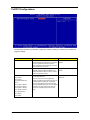
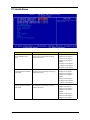
PC Health Status
Parameter
CPU Shutdown Temperature
(Function Enabled in ACPI
Mode)
Description
When the temperature of the CPU reaches th
default value, the system will shut down by
initiating beep sounds.
Options
90 degree C/ 194 degree F
60 degree C/ 140 degree F
70 degree C/ 158 degree F
80 degree C/ 186 degree F
Disabled
100 degree C/ 212 degree F
110 degree C/ 230 degree F
120 degree C/ 248 degree F
CPU Warning
Temperature(Function Enabled
in ACPI Mode
When the temperature of the CPU reaches th
default value, the system will give warning by
initiating beep sounds.
85 degree C/ 185 degree F
55degree C/ 131 degree F
65 degree C/ 149 degree F
75 degree C/ 167 degree F
Disabled
95 degree C/ 203 degree F
105 degree C/ 221 degree F
115 degree C/ 239 degree F
System Shutdown
Temperature(Function Enabled
in ACPI Mode
When the temperature of the system reaches the
default value, the system will shut down by
initiating beep sounds.
60 degree C/ 140 degree F
30degree C/ 86 degree F
40 degree C/ 104 degree F
50 degree C/ 122 degree F
Disabled
70degree C/ 158 degree F
80 degree C/ 186 degree F
90 degree C/ 194 degree F
53
Veriton 3500/5500/7500
Parameter
System Warning
Temperature(Function Enabled
in ACPI Mode
Description
When the temperature of the system reaches the
default value, the system will give warning by
initiating beep sounds.
Options
55 degree C/ 131 degree F
25degree C/ 77 degree F
35 degree C/ 95 degree F
45 degree C/ 113 degree F
Disabled
65degree C/ 149 degree F
75 degree C/ 167 degree F
85 degree C/ 185 degree F
Chapter 2
54
Frequency Control
The following table describes the parameters found in this menu.
Parameter
55
Description
Processor
Indicates the type of processor installed in your computer.
Processor Spee
Indicates the processor speed.
Veriton 3500/5500/7500
System Security
The Setup program has a number of security features to prevent unauthorized access to the system and its
data.
Supervisor Password
To set a password:
1.
At the prompt, type your password. Your password can be up to 8 alphanumeric characters. When you
type the characters, they appear as asterisks on the password screen box.
2.
After typing the password, press e.
3.
At the next prompt, re-type your password and press e again to confirm the new password. After the
password entry, the screen automatically reverts to the main screen.
To disable the password, press e when prompted to enter the password. The screen displays a message
confirming that the password has been disabled.
Chapter 2
56
57
Veriton 3500/5500/7500
User Password
IMPORTANT:To show the “Set User Password”:
1. Choose “Set Superviser Password” and press e.
2. Type the password and then press e.
3. Confirm the password, and then press
e.
4. The screen as below with “Set User Password” enabled will be shown.
To set a password:
1.
At the prompt, type your password. Your password can be up to 8 alphanumeric characters. When you
type the characters, they appear as asterisks on the password screen box.
2.
After typing the password, press e.
3.
At the next prompt, re-type your password and press e again to confirm the new password. After the
password entry, the screen automatically reverts to the main screen.
To disable the password, press e when prompted to enter the password. The screen displays a message
confirming that the password has been disabled.
Chapter 2
58
Bypassing the Password
If you forgot your password, you can bypass the password security feature thru hardware configuration.
RTC Battery
Follow these steps to bypass the password:
1.
Turn off and unplug the system.
2.
Open the system housing. Take off battery and short it.
3.
Place on RTC battery, reboot the system and enter setup menu, to load default setting.
Clear CMOS
Follow these steps to bypass the password:
1.
Reset CMOS, by adjusting JP2 to 2-3
2.
Reboot the system.
3.
Adjust the JP2 back to 1-2
NOTE: Please refer to the following
JP2: Clear CMOS
JP2
59
CMOS Check
1-2
Normal
2-3
Clear CMOS
Veriton 3500/5500/7500
Load Default Settings
You need to reload the BIOS default settings every time you make changes to your system hardware
configuration (such as memory size, CPU type, hard disk type, etc.); otherwise, BIOS will keep the previous
CMOS settings. Selecting this option displays the following dialog box:
Choosing Yes enables BIOS to automatically detect the hardware changes that you have made in your
system. This option also allows you to restore the default settings.
Choosing No returns you to the main menu without loading the default settings.
Chapter 2
60
Exiting Setup
To exit the BIOS utility, simply press
^. The following dialog box appears:
Select Yes to exit Setup. Select No to return to the main menu.
If you have made changes in the parameter settings, you will be asked if you want to keep the changes made
to the BIOS. Select Yes to save your changes before you exit Setup. Select No to discard all changes and exit
Setup.
61
Veriton 3500/5500/7500
Advanced Options
NOTE:
The Advanced Options menu is available only when you press a+o in the main menu.
The “Advanced Options” menu allows you to configure the system memory and PCI device settings.
The following screen shows the Advanced Options parameter:
CAUTION: Do not change any settings in the Advanced Options menu if you are not a qualified technician to
avoid damaging the system.
Product Information
Selecting “Product Information” from the Advanced Options menu displays the following screen:
This menu lets you configure the system memory.
The following table describes the parameters found in this sub-menu.
Chapter 2
62
Parameter
Description
System BIOS ID
R01-A3. BIOS real versio
BIOS release date
BIOS release date
Advanced BIOS Features
Selecting “Advanced BIOS Features” from the Advanced Options menu displays the following screen:
The following table describes the parameters found in the sub- menu. Settings in boldface are the default and
suggested settings.
63
Veriton 3500/5500/7500
.
Parameter
Description
Options
CPU L1 & L2 Cache
CPU L1 & L2 cache enabled
Enabled/ Disabled
Swap Floppy Drive
If the system has two floppy drives, choose enabled to
assign physical drive B to logical drive A and vice versa.
Disabled/Enabled
Boot Up Floppy Seek
If the item is enabled, BIOS will test floppy drives to
determine whether they have 40 or 80 tracks.
Disabled/Enabled
Boot Up NumLock Status
Selects power on state for NumLock.
On/ Off
Fast: Lets chipset control Gate A20
Fas /Normal
Gate A20 Option
Normal: A pin in the keyboard controller, controls Gate 20.
Default is fast.
Typematic Rate Setting
Keystrokes repeat at a rate determined by the keyboard
controller-- when enabled, the typematic rate and typematic
delay can be selected.
Disabled/Enabled
*Typematic Rate (Chars/Sec) 6
*Typematic Delay (MSec) 250
APIC Mode
Advanced Interrupt Controller. The I/O APIC handles
interrupts very differently than the 8259. (Refer to ICH4
EDS Rev 1.0 P6-39, 6.8)
Enabled
Disabled
MPS Version Control For OS Multi CPU for NT. system
1.4/ 1.1
OS Select For DRAM >
64MB
Select OS2 only if you are running OS/2 operating syste
with greater than 64MB of RAM on the system.
Non-OS2
Report No FDD for WIN 95
Fow WIN 95
No
OS2
Yes
Advanced Chipset Features
Selecting “Advanced BIOS Features” from the Advanced Options menu displays the following screen.
The following table describes the parameters found in the sub-menu. Settings in boldface are the default and
suggested settings.
Chapter 2
64
.
Parameter
DRAM Timing Selectable
Description
SDRAM Timing
Option
By SPD
Manual
CAS Latency Time
The default setting by your DRAM’s SPD.
1.5/2/2.5/3
Active to Precharge Delay
The default setting by your DRAM’s SPD.
7/6/5
DRAM RAS #to CAS# Delay The default setting by your DRAM’s SPD.
DRAM RAS# Precharge
3/2
The default setting by your DRAM’s SPD.
3/2
Memory Frequency fo
Memory frequency default setup.
Auto/ DDR200/DDR266
System BIOS Cacheable
E.F segment shadow RAM cacheable.
Enabled/Disabled
Video BIOS Cacheable
C segment shadow RAM cacheable.
Enabled/Disabled
Video RAM Cacheable
A.B segment shadow RAM cacheable.
Disabled/Enabled
Memory Hole at 15M-16
The system will reserve 15-16 MB address for
the add-on card.
Disabled/Enabled
Delayed Transaction
ICH4 enables delayed transactions for internal
register, FWH, and LPC I/F accesses.
Enabled/Disabled
Delay Prior to Thermal
Enables Pentium 4 thermal function - 16 miuntes
after POST.(only for ACPI OS
16/4/8/32 minutes
AGP Aperture Size (MB)
Aperture size: the size of the system memory for
AGP card. Options to decide how many size for
AGP card.
64/4/8/16/32/128/256
On-Chip Video Window size
Aperture size for on-board CPU.
128MB/64MB/Disabled
On-Chip Frame Buffer size
Frame buffer size for on-chip VGA.
8MB/1MB/512MB
Integrated Peripherals
65
Veriton 3500/5500/7500
The following table describes the parameters found in the sub-menu. Settings in boldface are the default and
suggested settings.
Parameter
UART Mode Select
Description
Option
Selects the UART as Serial Port (Normal) or IRDA or
ASKIR.
Normal
Selects the speed of UR2 Duplex Mode.
Half
IrDA
ASKI
UR2 Duplex Mode
Full
TxD, RxD Polarity Active
Selects the speed of TxD, RxD Polarity Active.
Lo, Hi
Lo, Lo
Hi, L
Hi, H
Use IR Pins
Use IR Pins as IR-Rx2Tx2 or RxD2, TxD2
IR-Rx2Tx2
RxD2, TxD2
Power Management Setup
Selecting “Power Management Setup” from the Advanced Options menu displays the following screen:
Chapter 2
66
The following table describes the parameters found in the sub-menu. Settings in boldface are the default and
suggested settings.
67
Veriton 3500/5500/7500
Parameter
Description
ACPI Functiont
ACPI power management
ACPI Suspend Type
Selects the ACPI Suspend Type as S1&S3, S3 (STR,
Suspend to RAM) or S1 (POS, Power On Suspend
Option
Enabled
Disabled
S1&S3
S3 (STR)
S1 (POS)
Video Off Method
Turn off the video by DPMS or Blank Screen or V/H SYNC
+ Blank Screen
V/H SYNC+BLANK
Turn off the video when entering the Suspend mode.
Yes
Blank Screen
DPMS
Video Off In Suspend
No
Suspend Type
When entering the Suspend mode, Stop Grant won’t stop
CPU Clock, PwrOn (Power On) Suspend will.
Stop Grant
MODEM Use IRQ
This item lets you set an IRQ for the modem.
3, 4, 5, 7, 9, 10, 11, and N/A
Primary IDE 0*
To enable or disable the detection of Primary IDE 0 (HDD)
activities for power down state transition.
Disabled
Primary IDE 1*
To enable or disable the detection of Primary IDE 1 (HDD)
activities for power down state transition.
Disabled
Secondary IDE 0*
To enable or disable the detection of Secondary IDE 0
(HDD) activities for power down state transition.
Disabled
Secondary IDE 1*
To enable or disable the detection of Secondary IDE 1
(HDD) activities for power down state transition.
Disabled
FDD, COM, LPT port*
To enable or disable the detection of FDD, COM port, and
LPT port activities for power down state transition.
Disabled
PCI PIRQ [A-D]#*
To enable or disable the detection of PCI PIRQ [A-D]#
activities for power down state transition.
Disabled
PwrOn Suspend
Enabled
Enabled
Enabled
Enabled
Enabled
Enabled
NOTE: These are global timer events.
The following table describes the parameters found in the sub-menu.
Frequency Control
Selecting “ Frequency Control” from the Advanced Options menu displays the following screen:
Chapter 2
68
The following table describes the parameters found in the sub-menu.
Parameter
CPU Clock Ratio
Description
Core Clock Frequency to System Bus Ratio (RO)
Option
The option items vary
depending on your BIOS.
Min=10
Max=24
Key in a DEC number
Auto Detect PCI CLK
Detect PCI card.
Disabled/Enabled
If the default is set to Disabled, then the PCI slot clock will
be turned off and vice versa.
Spread Spectru
This parameter let you enable or disable the spread
spectrum.
+/-0.25%
Disabled
-0.5%
+/-0.5%
+/-0.38
CPU Host/PCI Clock
Front side bus frequency/PCI clock.
Default
100/33 Mhz
105/35 Mhz
108/36 Mhz
114/38Mhz
120/40Mhz
123/41Mhz
126/36Mhz
69
Veriton 3500/5500/7500
Chapter 3
Machine Disassembly and Replacement
This chapter contains step-by-step procedures on how to disassemble the Veriton 3500/ 5500/ 7500 and the
Veriton 3500G/ 5500G/ 7500G desktop computer for maintenance and troubleshooting.
To disassemble the computer, you need the following tools:
q
Wrist grounding strap and conductive mat for preventing electrostatic discharge
q
Flat-bladed screwdriver
q
Phillips screwdriver
q
Hexagonal screwdriver
q
Plastic stick
NOTE: The screws for the different components vary in size. During the disassembly process, group the
screws with the corresponding components to avoid mismatches when putting back the components.
Chapter 3
70
General Information
Before You Begin
Before proceeding with the disassembly procedure, make sure that you do the following:
71
1.
Turn off the power to the system and all peripherals.
2.
Unplug the AC adapter and all power and signal cables from the system.
Veriton 3500/5500/7500
Veriton 3500/ 3500G Disassembly Flow Chart
Main Unit
RTC Battery
Front Panel
Housing Cover
Power Supply
Rotate Bracket
W/ DVD-ROM
& FDD Module
DIMM
USB/Audio
Board Module
USB Cable
Front Bezel
EMI Audio
Cover
DVD-ROM
Power switch
cable
FDD
HDD Bracket
Intrusion
Alarm Cable
Module
HDD
USB/Audio
Board
AGP VGA
Card
LAN Card
HDD Module
CPU Fan Sink
CPU
LED Activity
Indicators
Main Board
I/O port
Bracket
Memory Stick
Cable
NOTE: There is no AGP VGA slot for Veriton 3500.
Chapter 3
72
Disassembling the Veriton 3500/ 3500G
Opening the Housing
This section tells you how to open the housing cover when you need to install additional components inside
the system unit.
CAUTION: Before you proceed, make sure that you have turned off the system and all peripherals connected
to it.
Removing the Housing Cover
73
1.
Place the system unit on a flat, steady surface.
2.
Turn the housing back.
3.
Slide the upper case back out about an inch and then gently pull it outward to detach it from the housing.
Veriton 3500/5500/7500
Removing the Front Panel
1.
See “Removing the Housing Cover” on page 73
2.
Remove the four screws as shown here.
3.
Detach the front bezel from the front panel gently in the way as shown here.
Removing the AGP VGA Card
1.
See “Removing the Housing Cover” on page 73
2.
Remove the screw as shown here and then remove the AGP VGA card from the slot.
NOTE: There is no AGP VGA slot for Veriton 3500.
NOTE: When you turn on the system, BIOS automatically detects and assigns resources to the PCI or AGP
devices.
Chapter 3
74
Removing the LAN Card
1.
See “Removing the Housing Cover” on page 73
2.
Remove the screw as shown below and then remove the modem card from the slot.
Removing the EMI Audio Cover
1.
See “Removing the Housing Cover” on page 73
2.
Press and then remove the EMI audio cover from the lower case.
Removing the FDD and DVD Frame
1.
See “Removing the Housing Cover” on page 73
2.
Push the two latches of both sides then lift up the FDD and DVD frame
.
75
3.
Disconnect the floppy disk drive cable and floppy disk drive power connector from the floppy disk drive.
4.
Disconnect the DVD-ROM power cable, DVD-ROM IDE cable, and audio cable from the DVD-ROM drive.
Veriton 3500/5500/7500
5.
Disconnect the intrusion alarm cable from the main board and then pull the FDD and DVD frame from the
lower case
.
6.
Remove the floppy disk drive cable and optical drive IDE cable from the main board.
.
7.
Remove the four screws as shown here then detach the DVD-ROM drive from the frame.
8.
Remove the four screws as shown here then detach the floppy disk drive from the frame.
Chapter 3
76
Removing the Intrusion Alarm Cable Module
1.
See “Removing the Housing Cover” on page 73
2.
See “Removing the FDD and DVD Frame” on page 75
3.
Disconnect the cable from the main board , use the flat screwdriver to release the latches and then detach
the intrusion alarm cable module from the FDD and DVD frame.
Removing the DIMM
77
1.
See “Removing the Housing Cover” on page 73
2.
See “Removing the FDD and DVD Frame” on page 75”
3.
Press the levers on both sides of the DIMM socket outward to release the DIMM, and then gently pull the
DIMM out to remove it.
4.
Put the levers back to the original position.
Veriton 3500/5500/7500
Removing and Installing the RTC Battery
1.
See “Removing the Housing Cover” on page 73
2.
Press the latch to release the RTC battery, lift up the RTC battery. To install the RTC battery, put it back
and press it into the correct position to secure it well.Press the latch to release the RTC battery, lift up the
RTC battery. To install the RTC battery, put it back and press it into the correct position to secure it well.
.
Removing the Power Switch Cable
1.
See “Removing the Housing Cover” on page 73
2.
See “Removing the FDD and DVD Frame” on page 75”
3.
Disconnect the power switch cable from the main board, release the latches by using a flat screwdriver an
dthen detach the power switch cable from the FDD and DVD Frame.
Chapter 3
78
Removing the USB/ Audio Board
1.
See “Removing the Housing Cover” on page 73
2.
See “Removing the FDD and DVD Frame” on page 75
3.
See “Removing the LAN Card” on page 75
4.
Disconnect the memory stick cable and USB cable from the main board.
.
79
5.
Disconnect the memory stick cable and USB cable from the USB/ audio board.
6.
Remove the two screws as shown here and then detach the USB/ audio board from the lower case.
Veriton 3500/5500/7500
Removing the Hard Disk Drive
1.
See “Removing the Housing Cover” on page 73
2.
See “Removing the FDD and DVD Frame” on page 75
3.
Disconnect the hard disk drive IDE from the main board. Detach the hard disk drive power connector and
hard disk drive IDE cable from the hard disk drive.
4.
Remove the two screws as shown here and then hold the hard disk drive frame.
5.
Slide the hard disk drive frame to the right and then gently move it inward to detach it from
the lower case. Remove the four screws as shown and then detach the hard disk drive from the frame.
Chapter 3
80
Removing the LED Activity Indicators
1.
See “Removing the Housing Cover” on page 73.
2.
See “Removing the FDD and DVD Frame” on page 75”
3.
See “Removing the Hard Disk Drive” on page 80
4.
Disconnect the power LED, hard disk drive activity LED and network activity cables from the main board.
.
5.
Detach the network activity cable, power LED and hard disk drive activity LED cables from the housing.
.
81
Veriton 3500/5500/7500
Removing the Power Supply
1.
See “Removing the Housing Cover” on page 73.
2.
Disconnect the FDD power connector from the FDD drive and the DVD-ROM power connector from the
DVD-ROM drive.
3.
Remove the hard disk drive power connector from the hard disk drive.
4.
Disconnect the main power connector and 12 Volt. power connector from the main board. Remove the
three screws that hold the power supply to the housing and detach the power supply from the housing
Removing the CPU Fan Sink
1.
See “Removing the Housing Cover” on page 73
2.
See “Removing the FDD and DVD Frame” on page 75”
3.
Disconnect the fan sink cable from the main board, and then release the two levers on both sides of the
fan sink.
.
Chapter 3
82
4.
Remove the CPU fan sink from the main board and then put the levers back to their original positions.
WARNING:The heatsink becomes very hot when the system is On. Never touch the heatsink with any
metal or with your hands.
Removing and Installing the Processor
1.
See “Removing the Housing Cover” on page 73
2.
See “Removing the FDD and DVD Frame” on page 75”
3.
See “Removing the CPU Fan Sink” on page 82
Pull the socket lever up to release the processor pins from the socket holes an pull out the processor from the
socket.
4.
Before putting back the processor back to its correct position, please note that the side with the triangle
mark on the processor should align with the one on the socket. After putting the processor back to the
socket, put the socket lever back to its original position to scure the processor.
.
83
Veriton 3500/5500/7500
Removing the System Main board
1.
See “Removing the Housing Cover” on page 73
2.
See “Removing the FDD and DVD Frame” on page 75
3.
See “Removing the AGP VGA Card” on page 74
4.
See “Removing the LAN Card” on page 75
5.
Before you remove the system main board, make sure that all cables connected to the main board are
removed.
6.
Remove the eight screws as shown here then detach the main board from the lower case.
Removing the I/O Port Bracket
1.
See “Removing the Housing Cover” on page 73
2.
See “Removing the FDD and DVD Frame” on page 75
3.
See “Removing the AGP VGA Card” on page 74
4.
See “Removing the LAN Card” on page 75
5.
See “Removing the System Main board” on page 84
6.
Release the I/O port bracket from the housing and then detach it from the housing..
Chapter 3
84
Veriton 5500/ 5500G Disassembly Procedure Flowchart
Main Unit
LED Activity
Indicators
Front Panel
Housing Cover
Intrusion
Alarm Cable
Module
Front Panel W/
Empty Cover
Empter Cover
Power Switch
Cable
Dummy Link
Bar
AGP VGA
Card
Modem Card
USB/Audio
Board Module
RTC Battery
USB Cable
CPU Fan Sink
DIMM
Main Board
CPU
HDD
Link Bar
FDD
Memory Stick
Cable
I/O Port
Bracket
Power Supply
USB/ Audio
Board
CD-ROM
DVD-ROM
NOTE: There is no AGP slot for Veriton 5500.
85
Veriton 3500/5500/7500
Disassembling the Veriton 5500/ 5500G
Open the Housing Cover
This section tells you how to open the housing cover when you need to install additional components inside
the system unit.
CAUTION: Before you proceed, make sure that you have turned off the system and all peripherals connected
to it.
Removing the Housing Cover
1.
Turn off the system power and unplug all cables.
2.
Place the system unit on a flat, steady surface.
3.
Turn the two thumbscrews counterclockwise to remove the cover. Set the screws aside. You will need
them when replacing the housing cover.
4.
Hold the sides of the cover with both hands. Slide it back about an inch and then gently pull it outward to
detach it
.
Removing the Front Panel
1.
See “Removing the Housing Cover” on page 86
2.
Release the latches as shown here and then detach the front bezel from the front panel gently in the way
as shown here.
Chapter 3
86
Removing the Empty Cover
1.
See “Removing the Housing Cover” on page 86
2.
See “Removing the Front Panel” on page 86
3.
Release the latches as shown here and then detach the empty cover from the front panel
.
Removing a Dummy Link Bar
4.
See “Removing the Housing Cover” on page 86
5.
To remove a link bar, remove the one screw that secures the link bar to the housing. Slide the dummy link
bar in the direction as shown here and then lift it up.
.
Removing a Link Bar
1.
See “Removing the Housing Cover” on page 86
2.
To remove a link bar, remove the screw that secures it to the housing. Slide the dummy link bar in the
direction as shown here and then lift it up.
NOTE: Before detaching the link bar from the housing, make sure that the cables connected to HDD and FDD
are detached.
87
Veriton 3500/5500/7500
Removing the AGP VGA Card
1.
See “Removing the Housing Cover” on page 86
2.
Remove the screw on the bracket of the AGP card. Set the screw aside, you will need it when inserting
the AGP card.
3.
Gently pull out the AGP card to remove it from the AGP slot
.
NOTE: There is no AGP slot for Veriton 5500.
NOTE: When you turn on the system, BIOS automatically detects and assigns resources to the PCI or AGP
devices.
Removing the Modem Card
1.
See “Removing the Housing Cover” on page 86
2.
Remove the one screw as shown below and then remove the modem card from the PCI slot
.
NOTE: When you turn on the system, BIOS automatically detects and assigns resources to the PCI orAGP.
Removing the USB/ Audio Board Module
1.
See “Removing the Housing Cover” on page 86
2.
See “Removing the Modem Card” on page 88
3.
Disconnect the USB cable and the memory stick cable from the main board
.
4.
Remove the two screws as shown here and then detach the USB/ Audio board
Chapter 3
88
.
5.
Disconnect the USB cable and memory stick cable from the USB/ Audio board consecutively.
Removing a DIMM
89
1.
See “Removing the Housing Cover” on page 86
2.
See “Removing a Dummy Link Bar” on page 87
3.
Press the levers on both sides of the DIMM socket outward to release the DIMM, and then gently pull the
DIMM out to remove it.
4.
Put the levers back to the original position.
Veriton 3500/5500/7500
Removing the CPU Fan Sink
1.
See “Removing the Housing Cover” on page 86
2.
See “Removing a Dummy Link Bar” on page 87
3.
Detach the fan/heatsink cable connector and release the two CPU fan sink levers from the CPU fan sink
socket carefully, and then lift the fan/heatsink from the processor.
4.
Press down the levers back to their original position
.
WARNING:The heatsink becomes very hot when the system is On. Never touch the heatsink with any
metal or with your hands.
Chapter 3
90
Removing and Installing the Processor
1.
See “Removing the Housing Cover” on page 86
2.
See “Removing a Dummy Link Bar” on page 87
3.
See “Removing the CPU Fan Sink” on page 90
4.
Pull the socket lever up to release the processor pins from the socket holes an pull out the processor from
the socket..
5.
Before putting back the processor back to its correct position, please note that the side with the triangle
mark on the processor should align with the one on the socket. After putting the processor back to the
socket, put the socket lever back to its original position to scure the processor.
.
Removing and Installing the RTC Battery
1.
See “Removing the Housing Cover” on page 86
2.
Press the latch to release the RTC battery, lift up the RTC battery. To install the RTC battery, put it back
and press it into the correct position to secure it well
..
91
Veriton 3500/5500/7500
Removing the Hard Diskette Drive and Floppy Diskette Drive
1.
See “Removing the Housing Cover” on page 86
2.
See “Removing a Dummy Link Bar” on page 87
3.
See “Removing a Link Bar” on page 87
4.
Turn the link bar over, and then detach the hard disk drive power connector and hard disk drive IDE cable
from the hard disk drive
.
5.
Detach the floppy disk drive power connector and floppy disk drive cable from the floppy disk drive.
6.
Detach the floppy disk drive cable and hard disk drive IDE cable from the main board.
7.
Remove the four screws as shown here and then detach the hard disk drive module from the link bar.
.
Chapter 3
92
8.
Remove the four screws as shown here and then detach the floppy disk drive module from the link bar
.
Removing the CD-RW & DVD-ROM Drive
93
1.
See “Removing the Housing Cover” on page 86.
2.
See “Removing the Front Panel” on page 86
3.
See “Removing a Dummy Link Bar” on page 87
4.
See “Removing a Link Bar” on page 87
5.
See “Removing the Hard Diskette Drive and Floppy Diskette Drive” on page 92
6.
Disconnect the optical drive IDE cable from the main board. Remove the four screws that hold the CDRW drive to the bracket frame.
7.
Disconnect the CD-RW power cable, audio cable , and CD-RW IDE cable from the CD-RW drive, and
then pull the CD-RW drive out carefully.
Veriton 3500/5500/7500
8.
Remove the two screws that hold the DVD-RW driver to the bracket frame.
9.
Disconnect the DVD-ROM power cable, DVD-ROM IDE cable, and audio cable from the DVD-ROM drive,
and pull out the DVD-ROM drive.
10. Detach the CD-ROM module and DVD-ROM module from the housing.
.
Chapter 3
94
Removing the Power Supply
1.
See “Removing the Housing Cover” on page 86
2.
See “Removing a Dummy Link Bar” on page 87
3.
See “Removing a Link Bar” on page 87
4.
Disconnect the FDD power connector from the FDD drive and the HDD power connector from the HDD..
5.
Disconnect the CD-RW power connector from CD-RW drive and DVD-ROM power connector from DVDROM drive.
6.
Disconnect the main power connector and 12 Volt. power connector from the main board. Remove the
four screws that hold the power supply to the housing and detach the power supply from the housing.
Removing the Intrusion Alarm Cable Module
1.
See “Removing the Housing Cover” on page 86
2.
Disconnect the cable as shown here, remove the one screw here, and then detach the intrusion alarm
cable module from the housing.
Removing the LED Activity Indicators Module
95
1.
See “Removing the Housing Cover” on page 86
2.
Press the LED activity indicators module to release the latches in the direction as shown here, and then
detach the module from the housing.
Veriton 3500/5500/7500
3.
Disconnect the power LED, hard disk drive activity LED and network activity cables from the main board.
Removing Power Switch Cable
1.
See “Removing the Housing Cover” on page 86
2.
See “Removing the Front Panel” on page 86
3.
Remove the power switch cable from the main board and release the latches by using a flat screwdriver.
4.
Press the power switch cable and then detach it from the housing
.
Chapter 3
96
Removing the System Main Board
1.
See “Removing the Housing Cover” on page 86
2.
See “Removing a Dummy Link Bar” on page 87
3.
See “Removing the AGP VGA Card” on page 88
4.
See “Removing the Modem Card” on page 88
5.
Before you remove the system main board, make sure that all cables connected to the main board are
removed.
6.
Remove the eight screws as shown here and then detach the main board from the housing
.
Removing the I/O Port Bracket
97
1.
See “Removing the Housing Cover” on page 86
2.
See “Removing a Dummy Link Bar” on page 87
3.
See “Removing the AGP VGA Card” on page 88
4.
See “Removing the Modem Card” on page 88
5.
See “Removing the System Main Board” on page 97
6.
Slide the bracket and then lift it up in the direction as shown.
Veriton 3500/5500/7500
Veriton 7500/ 7500G Disassembly Procedure Flowchart
The flowchart on the succeeding page gives you a graphical representation on the entire disassembly
sequence and instructs you on the components that need to be removed during servicing.
Main Unit
Left Panel
FDD Module
RTC Battery
HDD Module
DIMM
Right Panel
AGP VGA
Card
Front Panel
Modem Card
Main Board
Power Supply
CPU Fan Sink
USB/Audio
Board
Intrusion
Alarm Cable
LED Activity
Indicators W/
Power Swtich
Cable Module
CD-RW/
DVD-ROM
CPU
NOTE: There is no AGP VGA Slot for Veriton 7500.
Chapter 3
98
Disassembling the Veriton 7500/ 7500G
Opening the Housing
This section tells you how to open the housing cover when you need to install additional components inside
the system unit.
CAUTION: Before you proceed, make sure that you have turned off the system and all peripherals connected
to it.
Removing the Housing
1.
Turn off the system power and unplug all cables.
2.
Place the system unit on a flat, steady surface.
3.
Remove the four screws of the right panel and left panel using a screwdriver. Set the screws aside, you
will need them when replacing the panel of the unit.
4.
Slide the right panel out and then gently pull it outward to detach it from the housing. Do the same thing
to the left panel.
.
Removing the Front Panel
1.
See “Removing the Housing” on page 99
2.
Release the 6 latches as shown below that holds the front panel and then remove it from the housing
.
99
Veriton 3500/5500/7500
Removing the Modem Card
1.
See “Removing the Housing” on page 99. (Remove the left panel only)
2.
Remove the screw on the bracket of the modem card. Set the screw aside, you will need it when
reinserting the modem card
.
Removing the AGP VGA Card
1.
See “Removing the Housing” on page 99. (Remove the left panel only)
2.
Remove the screw on the bracket of the AGP card. Set the screw aside, you will need it when reinserting
the AGP card.
3.
Gently pull out the AGP card to remove it from the AGP slot.
.
4. Gently pull out the modem card to remove it from the PCI slot.
NOTE: There is no AGP VGA slot for Veriton 7500.
NOTE: When you turn on the system, BIOS automatically detects and assigns resources to the PCI or AGP
devices.
Chapter 3
100
Removing the USB/ Audio Board
101
1.
See “Removing the Housing” on page 99
2.
See “Removing the Front Panel” on page 99
3.
See “Removing the Modem Card” on page 100
4.
Disconnect the memory stick cable and USB cable from the main board
5.
Disconnect the memory stick cable and the USB cable from the audio board.
6.
Remove the two screws that hold the audio board, then remove it from the housing.
Veriton 3500/5500/7500
Removing the DVD-ROM and CD-RW Drive
1.
See “Removing the Housing” on page 99.
2.
See “Removing the Front Panel” on page 99
3.
Disconnect the optical drive IDE cable and audio cable from the main board..
4.
Remove the four screws holding the CD-RW drive to the housing
.
5.
Disconnect the CD-RW power cable, CD-RW IDE cable, and audio cable from the CD-RW, then remove
the CD-ROM drive from the housing.
Chapter 3
102
6.
Remove the four screws holding DVD-ROM to the housing
.
7.
Disconnect the DVD-ROM power cable, DVD-ROM IDE cable, and audio cable from the DVD-ROM, then
remove the DVD-ROM drive from the housing
.
Removing the Floppy Disk Drive
103
1.
See “Removing the Housing” on page 99. (Remove the left panel only)
2.
Disconnect the floppy disk drive cable from the main board and then remove the four screws holding the
diskette drive.
Veriton 3500/5500/7500
3.
Disconnect the floppy disk drive cable and the floppy disk drive power connector, then remove the
diskette drive from the housing
.
Removing the Hard Disk Drive
1.
See “Removing the Housing” on page 99. (Remove the left panel only)
2.
Disconnect the hard disk drive IDE cable from the main board and then remove the four screws that hold
the hard disk drive to the disk frame. Set the screws aside.
.
3.
Detach the hard disk drive power connector and hard disk drive IDE cable from the hard disk drive, then
detach the disk drive from the drive frame
.
Removing the Intrusion Alarm Cable Module
1.
See “Removing the Housing” on page 99. (Remove the left panel only)
2.
Disconnect the cable as shown here, remove the one screw here, and then detach the intrusion alarm
cable module from the housing.
Chapter 3
104
Removing a DIMM
1.
See “Removing the Housing” on page 99. (Remove the left panel only)
2.
Press the levers on both sides of the DIMM socket outward to release the DIMM, and then gently pull the
DIMM out to remove it
.
Removing the CPU Fan Sink
1.
See “Removing the Housing” on page 99. (Remove the left panel only)
2.
Detach the fan/heatsink cable connector and release the two CPU fan sink levers from the CPU fan sink
socket carefully, and then lift the fan/heatsink from the processor
.
3. Press down the levers back to their original position.
WARNING:The heatsink becomes very hot when the system is On. Never touch the heatsink with any
metal or with your hands.
105
Veriton 3500/5500/7500
Removing and Installing the Processor
1.
See “Removing the Housing” on page 99. (Remove the left panel only)
2.
See “Removing the CPU Fan Sink” on page 105.
3.
Pull the socket lever up to release the processor pins from the socket holes an pull out the processor from
the socket..
4.
Before putting back the processor back to its correct position, please note that the side with the triangle
mark on the processor should align with the one on the socket. After putting the processor back to the
socket, put the socket lever back to its original position to scure the processor.
.
Removing and Installing the RTC Battery
1.
See “Removing the Housing” on page 99. (Remove the left panel only)
2.
Put the housing to lying position with the open area facing upward.
3.
Press the latch to release the RTC battery, lift up the RTC battery. To install the RTC battery, put it back
and press it into the correct position to secure it well.
.
Chapter 3
106
Removing the Power Supply
1.
See “Removing the Housing” on page 99. (Remove the left panel only)
2.
Disconnect the FDD power connector from the FDD drive and the HDD power connector from the HDD.
3.
Disconnect the CD-RW power connector from the CD-RW drive and DVD-ROM power connector from the
DVD-ROM drive.
4.
Disconnect the main power connector and 12 Volt. power connector from the main board. Remove the
four screws that hold the power supply to the housing and detach the power supply from the housing
..
Removing the LED Activity Indicators With Power Switch Cable Module
107
1.
See “Removing the Housing” on page 99
2.
See “Removing the Front Panel” on page 99
3.
Release the latches as shown here and then press the LED activity indicators with power switch cable
module and then detach the whole module from the housing .
4.
Disconnect the power LED, hard disk drive activity LED , network activity and power swtich cables from
the main board.
Veriton 3500/5500/7500
Removing the Main Board
1.
See “Removing the Housing” on page 99. (Remove the left panel only)
2.
Put the housing to lying position with the open area facing upward.
3.
See “Removing the AGP VGA Card” on page 100
4.
See “Removing the Modem Card” on page 100
5.
Before you remove the system main board, make sure that all cables connected to the main board are
removed.
6.
Remove the eight screws holding the main board and then remove the main board from the housing.
Removing the I/O Port Bracket
1.
See “Removing the Housing” on page 99. (Remove the left panel only)
2.
Put the housing to lying position with the open area facing upward.
3.
See “Removing the AGP VGA Card” on page 100
4.
See “Removing the Modem Card” on page 100
5.
See “Removing the Main Board” on page 108
6.
Slide the bracket and then lift it up in the direction as shown
.
Chapter 3
108
109
Veriton 3500/5500/7500
Chapter 4
Troubleshooting
This chapter provides troubleshooting information for the Veriton 3500/5500/7500, and the Veriton 3500G/
5500G/7500G
!
Chapter 4
Power-On Self-Test (POST)
!
Index of Error Message
!
Index of Error Symptoms
!
Undetermined Problems
110
Power-On Self-Test (POST)
Each time you turn on the system, the Power-on Self Test (POST) is initiated. Several items are tested during
POST, but is for the most part transparent to the user.
The Power-On Self Test (POST) is a BIOS procedure that boots the system, initializes and diagnoses the
system components, and controls the operation of the power-on password option. If POST discovers errors in
system operations at power-on, it displays error messages on screen, generates a check point code at port
80h or even halts the system if the error is fatal.
The main components on the main board that must be diagnosed and/or initialized by POST to ensure system
functionality are as follows:
!
Microprocessor with built-in numeric co-processor and cache memory subsystem
!
Direct Memory Access (DMA) controller (8237 module)
!
Interrupt system (8259 module)
!
Three programmable timers (system timer and 8254 module)
!
ROM subsystem
!
RAM subsystem
!
CMOS RAM subsystem and real time clock/calendar with battery backup
!
Onboard parallel interface controller
!
Embedded hard disk interface and one diskette drive interface
!
Keyboard and auxiliary device controllers
!
1.44M floppy controller
!
I/O ports
!
One parallel port
!
One PS/2-compatible mouse port
!
OnePS/2-compatible keyboard port
NOTE: When Post executes a task, it uses a series of preset numbers called check points to be latched at
port 80h, indicating the stages it is currently running. This latch can be read and shown on a debug board.
The following table describes the BIOS common tasks carried out by POST. Each task is denoted by an
unique check point number. For other unique check point numbers that are not listed in the table, refer to the
corresponding product service guide.
Post Checkpoints List: The list may vary accordingly depending on your BIOS
.
Checkpoin
Description
CFh
Test CMOS R/W functionality
C0h
Early chipset initialization:
-Disable shadow RAM
-Disable L2 cache (socket 7 or below)
-Program basic chipset registers
C1h
Detect memory
-Auto-detection of DRAM size, type and ECC.
-Auto-detection of L2 cache (socket 7 or below)
111
C3h
Expand compressed BIOS code to DRAM
C5h
Call chipset hook to copy BIOS back to E000 & F000 shadow RAM.
01h
Expand the Xgroup codes locating in physical address 1000:0
02h
Reserved
03h
Initial Superio_Early _Init switch
Veriton 3500/5500/7500
.
Checkpoin
Description
04h
Reserved
05h
1. Blank out screen
06h
Reserved
07h
1. Clear 8042 interfac
08h
1. Test special keyboard controller for Winbond 977 series Super I/O chips.
2. Clear CMOS error flag
2. Initialize 8042 self-test
2. Enable keyboard interface.
09h
Reserved
0Ah
1. Disable PS/2 mouse interface (optional)
2. Auto detect ports for keyboard & mouse followed by a port & interface swap (optional).
3. Reset keyboard for Winbond 977 series Super I/Q chips.
0Bh
Reserved
0Ch
Reserved
0Dh
Reserved
0Eh
Test F000h segment shadow to see whether it is R/W-able or not. If test fails, keep
beeping the speaker.
0Fh
Reserved
10h
Auto detect flash type to load appropriate flash R/W codes into the run time area in F000
for ESCD & DMI support.
11h
Reserved
12h
Use walking 1’s algorithm to check out interface in CMOS circuitry. Also set real-time clock
power status, and then check for override.
13h
Reserved
14h
Program chipset default values into chipset. Chipset default values are MODBINable by
OEM customers.
15h
Reserved
16h
Initial Early_Init_Onboard_Generator switch.
17h
Reserved
18h
Detect CPU information including brand, SMI type (Cyrix or Intel) and CPU level (586 or
686)
19h
Reserved
1Ah
Reserved
1Bh
Initial interrupts vector table. If no special specified, all H/W interrupts are directed to
SPURIOUS_INT_HDLR & S/W interrupts to SPURIOUS_soft_HDLR.
1Ch
Reserved
1Dh
Initial Early_PM_INIT switch.
1Eh
Reserved
1Fh
Load keyboard matrix (notebook platform)
20h
Reserved
21h
HPM initialization (notebook platform
22h
Reserved
Chapter 4
112
.
Checkpoin
23h
Description
1. Check validity of RTC value:
e.g. a value of 5Ah is an invalid value for RTC minute.
2. Load CMOS settings into BIOS stack. If CMOS checksum fails, use default value
instead.
3. Prepare BIOS resource map for PCI & PnP use. If ESCD is valid, take into
consideration of the ESCD’s legacy information.
4. Onboard clock generator initialization. Disable respective clock resource to empty PCI
& DIMM slots.
5. Early PCI initialization
-Enumerate PCI bus number
-Assign memory & I/O resourc
-Search for a valid VGA device and VGA BIOS, and put it into C000:0
24h
Reserved
25h
Reserved
26h
Reserved
27h
Initialize INT 09 buffer
28h
Reserved
29h
1. Program CPU internal MTRR (P6 & PII) for 0-640K memory address.
2. Initialize the APIC for Pentium class CPU.
3. Program early chipset according to CMOS setup. Example: onboard IDE controller.
4. Measure CPU speed.
5. Invoke video BIOS.
2Ah
Reserved
2Bh
Reserved
2Ch
Reserved
2Dh
1. Initialize multi-language
2. Put information on screen display, including Award title, CPU type, CPU speed...
113
2Eh
Reserved
2Fh
Reserved
30h
Reserved
31h
Reserved
32h
Reserved
33h
Reset keyboard except Winbond 977 series Super I/O chips.
34h
Reserved
35h
Reserved
36h
Reserved
37h
Reserved
38h
Reserved
39h
Reserved
3Ah
Reserved
3Bh
Reserved
3Ch
Test 8254.
3Dh
Reserved
3Eh
Test 8259 interrupt mask bits for channel 1
3Fh
Reserved
40h
Test 8259 interrupt mask bits for channel 2.
41h
Reserved
42h
Reserved
Veriton 3500/5500/7500
.
Checkpoin
Description
43h
Test 8259 functionality
44h
Reserved
45h
Reserved
46h
Reserved
47h
Initialize EISA slot
48h
Reserved
49h
1. Calculate total memory by testing the last double word of each 64K page.
2. Program writes allocation for AMD K5 CPU
4Ah
Reserved
4Bh
Reserved
4Ch
Reserved
4Dh
Reserved
4Eh
1. Program MTRR of M1 CPU.
2. Initialize L2 cache for P6 class CPU & program CPU with proper cacheable range.
3. Initialize the APIC for P6 class CPU.
4. On MP platform, adjust the cacheable range to smaller one in case the cacheable
ranges between each CPU are not identical.
4Fh
Reserved
50h
Initialize USB
51h
Reserved
52h
Test all memory (clear all extended memory to 0)
53h
Reserved
54h
Reserved
55h
Display number of processors (multi-processor platform)
56h
Reserved
57h
1. Display PnP logo
2. Early ISA PnP initialization
-Assign CSN to every ISA PnP device.
58h
Reserved
59h
Initialize the combined Trend Anti-Virus code.
5Ah
Reserved
5Bh
(Optional Feature)
Show message for entering AWDFLASH.EXE from FDD (optional)
5Ch
Reserved
5Dh
1. Initialize Init_Onboard_Super_IO switch.
2. Initialize Init_Onboard_AUDIO switch.
5Eh
Reserved
5Fh
Reserved
60h
Okay to enter Setup utility; i.e. not until this POST stage can users enter the CMOS setup
utility
61h
Reserved
62h
Reserved
63h
Reserved
64h
Reserved
65h
Initialize PS/2 Mouse
66h
Reserved
Chapter 4
114
.
Checkpoin
67h
Description
Prepare memory size information for function call:
INT 15h ax=E820h
68h
Reserved
69h
Turn on L2 cach
6Ah
Reserved
6Bh
Program chipset registers according to items described in Setup& Auto-configuration
table.
6Ch
Reserved
6Dh
1. Assign resources to all ISA PnP devices.
2. Auto assign ports to onboard COM ports if the corresponding item in Setup is set to
“AUTO”
6Eh
Reserved
6Fh
1. Initialize floppy controller
70h
Reserved
71h
Reserved
72h
Reserved
73h
(Optional Feature)
2. Set up floppy related fields in 40: hardware.
Enter AWDFLASH.EXE if:
-AWDFLASH is found in floppy driv
-ALT+F2 is pressed
74h
Reserved
75h
Detect & install all IDE devices: HDD, LS120, ZIP,CDROM.....
76h
Reserved
77h
Detect serial ports & parallel ports
78h
Reserved
79h
Reserved
7Ah
Detect & install co-processor
7Bh
Reserved
7Ch
Reserved
7Dh
Reserved
7Eh
Reserved
7Fh
1. Switch back to text mode if full screen logo is supported.
-If errors occur, report errors & wait for keys
-If no errors occur or F1 key is pressed to continue:
Clear EPA or customization logo.
80h
Reserved
81h
Reserved
82h
1. Call chipset power management hook.
2. Recover the text fond used by EPA logo (not for full screen logo
3. If password is set, ask for password.
115
83h
Save all data in stack back to CMOS.
84h
Initialize ISA PnP boot devices.
Veriton 3500/5500/7500
.
Checkpoin
85h
Description
1. USB final Initialization
2. NET PC: Build SYSID structure
3. Switch screen back to text mode.
4. Set up ACPI table at top of memory.
5. Invoke ISA adapter ROMs.
6. Assign IRQs to PCI devices
7. Initialize APM
8. Clear noise of IRQs/
86h
Reserved
87h
Reserved
88h
Reserved
89h
Reserved
90h
Reserved
91h
Reserved
92h
Reserved
93h
Read HDD boot sector information for Trend Anti-Virus code
94h
1. Enable L2 cache
2. Program boot up speed
3. Chipset final initialization
4. Power management final initialization
5. Clear screen & display summary tabl
6. Program K6 write allocation
7 Program P6 class write combining .
95h
1. Program daylight saving
2. Update keyboard LED & typematic rate
96h
1. Build MP table
2. Build & update ESC
3. Set CMOS century to 20h or 19h
4. Load CMOS time into DOS timer tick
5. Build MSIRQ routing table
FFh
Chapter 4
Boot attempt (INT 19h)
116
POST Error Messages List
If you cannot run the diagnostics program tests but did receive a POST error message, use “POST Error
Messages List” to diagnose system problems. If you did not receive any error message, look for a description
of your error symptoms in “Error Symptoms List” on page 119 .
NOTE: When you have deemed it necessary to replace an FRU, and have done so, you must run a total
system check to ensure that no other activity has been affected by the change. This system check can
be done through the diagnostics program.
NOTE: Check all power supply voltages, switch, and jumper settings before you replace the main board. Also
check the power supply voltages if you have a “system no-power” condition.
If you are unable to correct the problem by using the “BIOS Messages List” table and “Error Symptoms List”
table, go to “Undetermined Problems” on page 123.
To diagnose a problem, first find the BIOS error messages in the left column. If directed to a check procedure,
replace the FRU indicated in the check procedure. If no check procedure is indicated, the first Action/FRU
listed in right column is the most likely cause.
BIOS Messages
Action/FRU
BIOS ROM checksum error - System halted
The checksum of the BIOS code in the BIOS chip is
incorrect, indicating the BIOS code may have become
corrupt. Contact your system dealer to replace the BIOS.
CMOS Battery Failed
The CMOS battery is no longer functional. Contact your
system dealer for a replacement the BIOS.
CMOS Checksum Error- defaults loaded
Checksum of CMOS is incorrect, so the system loads the
default equipment configuration. A checksum error may
indicate that CMOS has become corrupt. A weak battery
may have caused this error. Check the battery and replace
if necessary.
CPU at nnnn
Displays the running speed of CPU.
Display switch is set incorrectly
The display switch on the motherboard can be set to eithe
monochrome or color. This message indicates the switch is
set to a different setting than indicated in Setup. Determine
which setting is correct, and then either turn off the syste
and change the jumper, or enter Setup and change the
Video selection.
Press ESC to skip memory test
The user may press Esc to skip the full memory test.
Floppy disk(s) fail
Cannot find or initialize the floppy drive controller or the
drive. Make sure the controller is installed correctly, if no
floppy drives are installed, be sure the Diskette Drive
selection in Setup is set to NONE or AUTO.
HARD DISK initializing - Please wait a moment
Some hard drives require extra time to initialize.
HARD DISK INSTALL FAILURE
Cannot find or initialize the hard drive controller or the
drive. Make sure the controller is installed correctly. If no
hard drives are installed, be sure the Hard Drive Selection
in Setup is set to NONE.
Hard disk(s) diagnosis fail
The system may run specific disk diagnostic routines. This
message appears if one or more hard disks return an error
when the diagnostics run.
Keyboard Error Or No Keyboard Present
Cannot initialize the keyboard. Make sure the keyboard is
attached correctly and no keys are pressed during POST.
To purposely configure the system without a keyboard, set
the error halt condition in Setup to HALT ON ALL, BUT
KEYBOARD. The BIOS then ignores the missing keyboard
during POST.
Keyboard is locked out - Unlock the key
This message usually indicates that one or more keys hav
been pressed during the keyboard tests. Be sure n
objects are resting on the keyboard.
117
Veriton 3500/5500/7500
BIOS Messages
Action/FRU
Memory Test:
This message displays during a full memory test, counting
down the memory areas being tested.
Memory test fail
If POST detects an error during memory testing, additional
information appears giving specifics about the type and
location of the memory error.
Override enabled - Defaults loaded
If the system cannot boot using the current CMOS
configuration, the BIOS can override the current
configuration with a set of BIOS defaults designed for the
most stable, minimal-performance system operations.
Press TAB to show POST screen
System OEMs may replace the Phoenix Technologies
Award BIOS POST display with their own proprietary
display. Including this message in the OEM display permits
the operator to switch between the OEM display and the
default POST display.
Primary master hard disk fail
POST detects an error in the primary master IDE hard
drive.
Primary slave hard disk fail
POST detects an error in the secondary master IDE hard
drive.
Secondary master hard disk fail
POST detects an error in the primary slave IDE hard drive.
Secondary slave hard disk fail
POST detects an error in the secondary slave IDE hard
drive.
Chapter 4
118
Error Symptoms List
NOTE: To diagnose a problem, first find the error symptom in the left column. If directed to a check procedure,
replace the FRU indicated in the check procedure. If no check procedure is indicated, the first Action/
FRU listed in right column is the most likely cause.
Error Symptom
Action/FRU
Processor / Processor Fan
NOTE: Normally, the processor fan should be operative, and the processor clock setting should be
exactly set to match its speed requirement before diagnosing any processor problems.
Processor fan does not run but power supply
fan runs.
1. Ensure the system is not in power saving mode. See “Power
Management” in chapter 2.
2. With the system power on, measure the voltage of processor fa
connector. Its reading should be +12Vdc. Its reading should be
+12Vdc. If the reading shows normal, but the fan still does not
work, then replace a good fan.
3. Main board.
Processor test failed.
1. Processor
2. Main board.
Main board and Memor
NOTE: Ensure the memory modules are installed properly and the contact leads are clean before
diagnosing any system problems.
Memory test failed.
1. See "Memory"
2. Main board
Incorrect memory size shown or repeated
during POST.
1. Insert the memory modules in the DIMM sockets properly, then
reboot the system.
2. Memory module.
3. Main board.
System works but fails to enter power saving
mode when th Power Management Mode
is set to Enabled.
1. Enter BIOS Setup and load default settings.
In Windows Systems, check settings in Power Management
Property of Control Panel.
2. Reload software from Recovery CD.
Blinking cursor only; system does not work.
1.
2.
3.
4.
Diskette/IDE drive connection/cables
Diskette/IDE disk drives
See “Undetermined Problems”.
Main board
Diskette Driv
NOTE: Ensure the diskette drive is auto-setting in BIOS Setup and its read/write head is clean before
diagnosing any diskette drive problems.(If only one drive is installed, please make sure the
drive is connected to master connector or the drive is set to master.)
119
Media and drive are mismatched.
1. Ensure the diskette drive is configured correctly in the Disk
Drives of BIOS Setup.
2. Ensure the diskette drive is correctly formatted.
3. Diskette drive connection/cable
4. Diskette drive
5. Main board
Diskette drive does not work.
1. Ensure the diskette drive is not set to None in the Disk Drives of
BIOS Setup.
2. Diskette drive power
3. Diskette drive connection/cable
4. Diskette drive
5. Main board
Diskette drive read/write error.
1.
2.
3.
4.
Diskette.
Diskette drive cable.
Diskette drive.
Main board.
Veriton 3500/5500/7500
Error Symptom
Action/FRU
Diskette drive LED comes on for more than 2
minutes when reading data.
1.
2.
3.
4.
Diskette
Diskette drive connection/cable
Diskette drive
Main board
Diskette drive LED fails to light, and the drive
is unable to access for more than 2 minutes.
1.
2.
3.
4.
5.
Diskette
Diskette drive power
Diskette drive connection/cable
Diskette drive
Main board
Diskette drive test failed.
1.
2.
3.
4.
Diskette
Diskette drive
Diskette drive cable
Main board
Hard Disk Drive
NOTE: Ensure hard disk drive is configured correctly in BIOS Setup, cable/jumper are set correctly
before diagnosing any hard disk drive problems. (If only one drive is installed, please make
sure the drive is connected to master connector or the drive is set to master.)
Hard disk drive test failed.
1.
2.
3.
4.
Enter BIOS Setup and Load default settings.
Hard disk drive cable.
Hard disk drive.
Main board.
Hard disk drive cannot format completely.
1.
2.
3.
4.
Enter BIOS Setup and Load default settings.
Hard disk drive cable.
Hard disk drive.
Main board.
Hard disk drive has write error.
1. Enter BIOS Setup and Load default settings.
2. Hard disk drive.
Hard disk drive LED fails to light, but system
operates normally.
1. With the system power on, measure the voltage of hard disk LED
connector.
2. Hard drive LED cable.
CD/DVD-ROM Drive
NOTE: Ensure CD/DVD-ROM drive is configured correctly in BIOS Setup, cable/jumper are set
correctly and its laser beam is clean before diagnosing any CD/DVD-ROM drive problems.
CD/DVD-ROM drive LED doesn't come on
but works normally.
1. CD/DVD-ROM drive
CD/DVD-ROM drive LED flashes for more
than 30 seconds before LED shutting off.
1. CD/DVD-ROM may have dirt or foreign material on it. Check with
a known good disc.
2. CD/DVD-ROM is not inserted properly.
3. CD/DVD-ROM is damaged.
Software asks to reinstall disc.
Software displays a reading CD/DVD error.
CD/DVD-ROM drive cannot load or eject
when the system is turned on and its eject
button is pressed and held.
1. Disconnect all cables from CD/DVD-ROM drive except power
cable, then press eject button to try to unload the disk.
2. CD/DVD-ROM drive power.
3. CD/DVD-ROM drive
CD/DVD-ROM drive does not read and there
are no messages are displayed.
1. CD may have dirt or foreign material on it. Check with a known
good disc.
2. Ensure the CD/DVD-ROM driver is installed properly.
3. CD/DVD-ROM drive.
CD/DVD-ROM drive can play audio CD but
no sound output.
1.
2.
3.
4.
Ensure the headphone jack of the CD/DVD-ROM has an output.
Turn up the sound volume.
Speaker power/connection/cable.
CD/DVD-ROM drive.
Real-Time Clock
Real-time clock is inaccurate.
Chapter 4
1. Ensure the information in the Standard CMOS Feature of
BIOS Setup is set correctly.
2. RTC battery.
3. Main board
120
Error Symptom
Action/FRU
Audio
Audio software program invokes but no sound
comes from speakers.
1. Speaker power/connection/cable.
Modem
Modem ring cannot wake up system from
suspend mode.
1. For the External Modem, make sure Power on By Ring in BIOS
Setup or Power Management is set to Enabled. For the PCI
modem, make sure Wake up by PCI card is set to Enabled.
2. If PCI modem card is used, reinsert the modem card to PCI slot
firmly or replace the modem card.
3. In Win 98, ensure the telephone application is configured
correctly for your modem and set to receive messages and/or
fax.
Data/fax modem software program invokes
but cannot receive/send data/fax
1. Ensure the modem card is installed properly.
Fax/voice modem software program invokes
but has no sound output. (Data files ar
received normally; voice from modem cannot
be produced, but system sound feature works
normally.)
1. Ensure the modem voice-in cable from modem adapter card to
main board
Video and Monitor
Video memory test failed.
Video adapter failed.
Display problem:
- Incorrect colors
No high intensity
Missing, broken, or incorrect characters
1. Remove all non-factory-installed cards.
2. Load default settings (if screen is readable).
3. Main board
1.
2.
3.
4.
Monitor signal connection/cable.
Monitor
Video adapter card
Main board
Blank monitor (dark
Blank monitor (bright
Distorted image
Unreadable monitor
Other monitor problems
121
Display changing colors.
1. Monitor signal connection/cable
2. Monitor
3. Main board
Display problem not listed above (including
blank or illegible monitor).
1. “Monitor".
2. Load default settings (if screen is readable).
3. Main board
Veriton 3500/5500/7500
Error Symptom
Action/FRU
Parallel/Serial Ports
Execute “Load BIOS Default Settings” in BIOS Setup to confirm ports presence before diagnosing any parallel/serial
ports problems.
Serial or parallel port loop-back test failed.
1. Make sure that the LPT# or COM# you test is the same as the
setting in BIOS Setup.
2. Loop-back.
3. Main board.
Printing failed.
1. Ensure the printer driver is properly installed. Refer to the printer
service manual.
2. Printer.
3. Printer cable.
4. Main board.
Printer problems.
1. Refer to the service manual for the printer.
Keyboard
Some or all keys on keyboard do not work.
1. Keyboard
Power Supply
Pressing power switch does not turn off
system. (Only unplugging the power cord
from electrical outlet can turn off the system.)
1. Ensure the Soft-off by PWR-BTTN. in BIOS Setup of
Power Management is not set to Instant-off.
2. Power switch cable assembly
Pressing power switch does not turn on the
system.
1. Ensure the power override switch (situated at the back of the
machine, just above the connector for the power cable) is not set
to OFF.
2. Power switch cable assembly.
Executing software shutdown from
Windows98 Start menu does not turn off the
system. (Only pressing power switch can turn
off the system).
1. Load default settings.
2. Reload software from Recovery CD.
No system power, or power supply fan is not
running.
1. Power Supply
2. Main board
Other Problems
Any other problems.
Chapter 4
1. Undetermined Problems
122
Undetermined Problems
If an error message is present, go to “POST Error Messages List” on page 117. If you did not receive any
messages, if the symptom is listed in “or “Error Symptoms List” on page 119 . If you still cannot solve the
problem, continue with this check:
1.
Check the power supply voltages. If the voltages are correct continue with the following steps:
2.
Power off the system unit.
3.
Perform the following checks, one by one, until you have isolated the
problem FRU.
4.
Load default settings in setup.
5.
Check all main board jumper positions and switch settings.
6.
Check all adapter card jumper positions.
7.
Check all device jumper positions.
8.
Check all cables and connectors for proper installation.
9.
If the jumpers, switches and voltage settings are correct, remove or disconnect the following, one at a
time:
10. Non-Acer devices
!
External devices
!
Any adapter card (modem card, LAN card or video card, if installed)
!
CD/DVD-ROM drive
!
Diskette drive
!
Hard disk drive
!
DIMM
!
Processor
!
Main board
11. Power on the system unit.
12. Repeat steps 2 through 5 until you find the failing device or adapter.
123
Veriton 3500/5500/7500
Chapter 5
Jumper and Connector Information
Jumpers and Connectors
Refer to the following figure for the location of the jumpers and connectors on the main board:
Chapter 5
124
CN23
CN26
U24
BT1
CN13
CN12
CN9
CN6
U3
Main board (3500/ 5500/ 7500)(S88M/GL)
CN21
CN25
CN19
JP2
CN20
CN4
CN7
DIMM 2
DIMM 1
FN1
CN22
CN24
U21
U14
CN18
SL1
U8
SL2
SL3
CN2
125
CN3
CN8
CN10
CN17
CN16
CN11
FN2
CN14
Veriton 3500/5500/7500
CN23
CN26
U24
BT1
CN13
CN12
CN9
CN6
U3
Main board (3500G/ 5500G/ 7500G)(S88M/G)
CN21
CN25
CN19
JP2
CN20
CN4
CN7
DIMM 2
DIMM 1
FN1
CN22
CN24
U21
U14
CN18
SL1
U8
SL2
SL3
CN2
Chapter 5
CN3
CN8
CN10
CN17
CN16
CN11
SLT1
FN2
CN14
126
Connector Description
Label
Component
Label
Component
CN6
Game Port
SL2
PCI Slot 2
CN9
FDD Connector
SL3
PCI Slot 3
CN12
IDE 2 Connector
CN17
CD-in Connecto
CN13
IDE 1 Connector
CN16
Audio for Daughter Board
BT1
Battery
SLT1
AGP Slot
U24
FWH
CN11
Power Connector (12V)
CN23
Serial IRQ
CN14
Line-in (upper), Line-out(middle), Mic-in
(lower)
CN26
Power LED
CN10
Network (upper) and USB (lower) Ports
CN21
Power Button
CN8
Parallel port (upper) and Serial Ports (lower)
CN25
Audio FPIO Connector
CN3
Serial Ports
CN19
LAN Activity LED
CN2
PS2 Keyboard
JP2
1-2: Normal
FN2
3-pin Fan SYS Connector
CPU Socket
2-3: Clear CMOS
CN20
HDD LED Connector
U8
CN22
Intrusion Connector
FN1
3-pin Fan CPU Connector
CN24
Suspend Power LED
DIMM1
Memory Slot 1
U21
Intel ICH4 Chipset
DIMM2
Memory Slot 2
CN18
Front USB Connector
CN7
Power Connector
U14
Intel 845G/GL*
CN4
COM
PCI Slot 1
U3
SMSC
SL1
NOTE: There is no AGP VGA slot for S88M/GL.
NOTE: *: Intel 845 GL (Veriton 3500/ 5500/ 7500); Intel 845G (Veriton 3500G/ 5500G/ 7500G)
Jumper Setting
Jumper
JP2
Function and settings
1-2 Normal*
2-3 Clear CMOS
NOTE: *: Default Settings.
127
Veriton 3500/5500/7500
Chapter 6
FRU (Field Replaceable Unit) List
This chapter gives you the FRU (Field Replaceable Unit) listing in global configurations of Veriton 3500/
3500G, 5500/ 5500G, 7500/ 7500G. Refer to this chapter whenever ordering for parts to repair or for RMA
(Return Merchandise Authorization).
IMPORTANT: Please note WHEN ORDERING FRU PARTS, that you should check the most up-to-date
information available on your regional web or channel. For whatever reasons a part number change
is made, it will not be noted in the printed Service Guide. For ACER-AUTHORIZED SERVICE
PROVIDERS, your Acer office may have a DIFFERENT part number code to those given in the FRU
list of this printed Service Guide. You MUST use the local FRU list provided by your regional Acer
office to order FRU parts for repair and service of customer machines.
IMPORTANT:Please note that Acer Corporation sells only the parts listed in the following table.
Please be reminded that though some parts are disassembled in Chapter 3 for demonstration
purpose, Acer Corporation does not provide these parts.
NOTE: To scrap or to return the defective parts, you should follow the local government ordinance or
regulations on how best to dispose it, or follow the rules set by your regional Acer office on how to
return it.
NOTE: The number indicates the location shown on exploded diagram or “NS” indicates “Not shown” on it.
Chapter 6
128
Veriton 3500/ 3500G Exploded Diagram
Picture
No.
Part Name
Description
Floppy Disk Drive
3
FDD 1.44M MITSUMI/D353M3D
FDD 1.44MB 1"H MITSUMI/D353M3
Battery
129
Veriton 3500/5500/7500
Picture
No.
Part Name
Description
NS
RTC BATTERY LI 3V 200MAH
BATTERY LI 3V CR2032 200MAH
NS
IDE CABLE 40PIN 2C 300M
C.A.40P 2C 300MM HDD H34
8
FDD CABLE 34/34PIN 280MM H34
C.A.34/34P FDD 280MM H34
1-10
HDD LED CABLE 4PIN 500MM LX-45
W.A 4P/HDD LED 500MM LX-45
1-12
POWER LED CABLE 3PIN 500MM LX45
W.A 3P/PWR LED 500MM LX-45
NS
CDR CABLE 40/40PIN 300MM H3
C.A.40/40P CDR 300MM H34
Cable
Chapter 6
130
Picture
No.
Part Name
Description
1-8
MICRO SWITCH CABLE 2PIN 500MM
H34
C.A.2P MICRO SW 500MM H34
NS
AUDIO CABLE 4PIN 2CONNECTOR
520M
W.A 4P 2C AUDIO 520MM H61
1-9
POWER SWITCH CABLE 2PIN 500M
LX-45
W.A 2P/PWR SW 500MM LX-45
1-11
TURBO LED CABLE 2PIN 500MM LX-45 W.A 2P/TURBO LED 500MM LX-45
NS
AUDIO BOARD CABLE 10PIN 385MM
W.A 2C 10P AUDIO BD 385MM S88M
NS
USB CABLE 2CONNECTOR 10PIN
300M
C.A 2CONN USB/10P 300MM S88M
NS
MAINBOARD/S88M GL
S88M GL MB
Main board
131
Veriton 3500/5500/7500
Picture
No.
Part Name
Description
Board
NS
AUDIO/USB BOARD
S88M DAUGHTER BOARD
NS
POWER SUPPLY 160W AOPEN
FSP160-60SAV V.1
SPS 160WNOPFC FSP160-60SAV
V.1
1-6
UPPER CASE SECC H34A
ASSEMBLY UPPER CASE SECC
H34A
NS
LOWER CASE W/O LED CABLE,SWICH
CABLE,MICRO SWITCH CABLE
ASSEMBLY LOWER CASE SECC
H34A
1-4
ROTATE BRACKET H34A
ASSEMBLY ROTATE BRACKET
H34A
1-1
HDD BRACKET
BRACKET HDD SECC H34
Power Supply
Case/Cover/Bracket Assembly
Chapter 6
132
Picture
No.
Part Name
Description
1-5
I/O PPORT BRACKET W/ LABEL
ASSY. I/O BRACKET
7
FOOT STAND
ASSY FOOT STAND ABS 501 H34
NS
I/O PORT LABEL
Label I/O PORT 40.7x155 H34A-S88M
NS
SCREW
SCREW HDD FLAT 6#32 L9.8M
H34
NS
SCREW
SCREW MACH BDG #6-32*L8 NI
5
SCREW
SCRW TAP HEX ZINC M3*.5*5
SCREW
SCRW TAP HEX ZN #6*3/16"
SCREW
SCREW TAP HEX ZNIC #6-32*4/16"
Miscellaneous
Screws
1-3
4
1-2
NS
133
Veriton 3500/5500/7500
Picture
No.
NS
Chapter 6
Part Name
SCREW
Description
SCRW TAP PAN M3*8L 2LEAD
134
Veriton 5500/ 5500G Exploded Diagram
Picture
No.
Part Name
Description
Floppy Disk Drive
8
FDD 1.44M MITSUMI/D353M3D
FDD 1.44MB 1"H MITSUMI/D353M3
Battery
135
Veriton 3500/5500/7500
Picture
No.
Part Name
Description
NS
RTC BATTERY LI 3V 200MAH
BATTERY LI 3V CR2032 200MAH
NS
IDE CABLE 40PIN 3CONNECTOR
150+300M
C.A 40P 3C 150+300MM IDE H61
9
FDD CABLE 34PIN 2CONNECTOR
450M
C.A 34P 2C 450MM FDD H61
NS
IDE CABLE 40PIN 3CONNECTOR
150+300MM ATA66
C.A 40P 3C 150+300MM ATA66 H61
NS
AUDIO CABLE 4PIN 3CONNECTOR
520M
W.A 4P 3C(Y)520MM
AUDIO(COMAX)
1-8
POWER SWITCH CABLE 2PIN 300M
W/HOLDER
W.A 2P/PWR SW 300MM H61 W/
HOL
Cable
Chapter 6
136
Picture
No.
Part Name
Description
1-13
INTRUSION ALERT MICRO SWITCH
CABLE
ASSY MICRO/SW CABLE H4
VT5100
1-12
LED CABLE MODULE TURBO/HDD/
POWER
ASSEMBLY LED CABLE (A) H40
NS
AUDIO BOARD CABLE 2CONNECTOR
10PIN 380MM
W.A 2C 10P AUDIO BD 385MM S88M
NS
USB CABLE 2CONNECTOR 10PIN
300M
C.A 2CONN USB/10P 300MM S88M
NS
MAINBOARD/S88
S88M MAIN BOARD
NS
AUDIO BOARD
S88M DAUGHTER BOARD
Main board
Board
137
Veriton 3500/5500/7500
Picture
No.
Part Name
Description
Power Supply
3
POWER SUPPLY 200W DELTA DPS200PB-112A 01
SPS 200W PFC DPS-200PB-112A 01
1-9
UPPER CASE
ASSY UPPER CASE H40
1-10
LOWER CASE W/O LED
CABLE,SWITCH CABLE,MICRO
SWITCH CABLE
ASSY L CASE H40
1-5
EMPTY COVER 5.25"
5.25" EMPTY COVER H40 VERITON
1-4
LINK BAR
BAR LINK SECC T-.8 H40
1-11
FRONT PANEL W/POWER KNOB W/O
LOGO
ASSY F PNL VER H40 PRINT ACER
Case/Cover/Bracket Assembly
Chapter 6
138
Picture
No.
Part Name
Description
NS
I/O PORT BRACKET W/O LABEL
ASSY PORT BRACKET(S88M) H80
NS
NAME PLATE VT550
LBL NAME PLT49.6*9.6VT5500 H40
NS
I/O PORT LABEL
LBL I/O PORT 40.7X155 H34A-S88M
1-14
SCREW
SCREW TAP HEX ZNIC #6-32*4/16"
Miscellaneous
Screws
139
NS
SCREW
SCREW MACH BDG #6-32*L8 NI
NS
SCREW
SCRW MACH BDG #6-32*3/16" NI
10
SCREW
SCRW TAP HEX ZINC M3*.5*5
NS
SCREW
SCRW THUMB #6-32 NI
Veriton 3500/5500/7500
Picture
No.
4
Part Name
Description
SCREW
SCREW TAP HEX ZNIC #6-32*4/16"
SCREW
SCRW MACH FLAT M3*0.5P*8L NI
1-14
1-15
Chapter 6
140
Veriton 7500/ 7500G Exploded Diagram
Picture
No.
Part Name
Description
Floppy Disk Drive
2
FDD 1.44M MITSUMI/D353M3D
FDD 1.44MB 1"H MITSUMI/D353M3
Battery
141
Veriton 3500/5500/7500
Picture
No.
Part Name
Description
NS
RTC BATTERY 3V 200MAH
BATTERY LI 3V CR2032 200MAH
NS
IDE CABLE 40PIN 3CONNECTOR
150+300M
C.A 40P 3C 150+300MM IDE H61
4
FDD CABLE 34PIN 2CONNECTOR
350M
C.A 34P 2C 350MM FDD M19A/FU
NS
IDE CABLE 40PIN 3CONNECTOR
150+300MM ATA66
C.A 40P 3C 150+300MM ATA66 H61
NS
AUDIO CABLE 4PIN 2CONNECTOR
520M
W.A 4P 2C AUDIO 520MM H61
NS
POWER CABLE 160/330M
CABLE PWR/DC 160/330MM
Cable
Chapter 6
142
Picture
No.
Part Name
Description
1-15
INTRUSION ALERT MICRO SWITCH
CABLE 2PIN 500MM
W.A. 2P ALARM SW 500MM CABLE 2
1-8
LED CABLE MODULE POWER LED/
TURBO LED/HDD LED/POWER
SWITCH
ASSY HLD LX45
NS
AUDIO BOARD CABLE 10PIN 385MM
W.A 2C 10P AUDIO BD 385MM S88M
NS
USB CABLE 2CONNECTOR 10PIN
300M
C.A 2CONN USB/10P 300MM S88M
NS
MAINBOARD/S88M GL
S88M GL MB
NS
DAUGHTER BOARD
S88M DAUGHTER BOARD
Main board
Board
143
Veriton 3500/5500/7500
Picture
No.
Part Name
Description
Power Supply
NS
POWER SUPPLY 200W DELTA DPS200PB-112B 01
SPS 200W PFC DPS-200PB-112B 01
1-1
RIGHT DOOR
CVR R SECC T-.8 LX45
1-2
LEFT COVER
CVR L SECC T-.8 H80
1-7
FRONT BEZEL
ASSY BZL VERTION NEW LOGO
H80
1-6
LOWER CASE W/TOP
COVER,MAINBOARD TRAY,USB
HOLDER
ASSY L-CASE W/USB HOLE H80
NS
I/O PORT BRACKET
ASSY PORT BRACKET(S88M) H80
Case/Cover/Bracket Assembly
Miscellaneous
Chapter 6
144
Picture
No.
Part Name
Description
NS
NAME PLATE VT750
LBL NAME PLT49.6*9.6VT7500 H80
NS
RUBBER FOOT
RUBBER FOOT T-6.8 IDB
NS
I/O PORT LABEL
LBL I/O Port 40.7x155 H34a-88M
NS
SCREW
SCRW HEX I#4-40/O#4-40 L7.5 NI
1-17
SCREW
SCRW MACH PAN M2*10L
NS
SCREW
SCRW MACH BDG #6-32*3/16" NI
1-10
SCREW
SCRW MACH FLAT M3*0.5P*8L NI
Screws
145
Veriton 3500/5500/7500
Picture
No.
9
Part Name
Description
SCREW
SCRW TAP HEX ZINC M3*.5*5
SCREW
SCREW TAP HEX ZNIC #6-32*4/16"
1-18
8
1-9
Chapter 6
146
Appendix A
Model Definition and Configuration
Veriton 3500/5500/7500
1.
Brand No: S88M/ GL MB
2.
Project Name/ Code: S88M / 91.31V01.301(Veriton 3500)
S88M/ 91.31V01.201(Veriton 5500)
S88M/ 91.31V01.101(Veriton 7500)
3.
Description
S88M/GL is positioned to be the first Main Board product that supports the latest INTEL Chipset Brookdale-GL
technology with DDR DIMM module. As a technology leader in the PC market, S88M/GL stands for not only
the image of the best performance product for Intel’s next generation mainstream platform but also a real time
to market product for all customers’ demand to win the market entrance advantage.
S88M /GL Main Board, using INTEL Pentium 4 Processor in the 478 Pin package, delivers a mainstream
desktop platform solution.
With INTEL chipsets Brookdale-GL GMCH and ICH4, S88M/ GL provides the processor interface, DDR
(Double Data rate) interface, and HUB interface. The CPU interface supports the INTEL Pentium 4 processor
subset of the Extended Mode of Scalable Bus Protocol. INTEL Brookdale-GL is optimized for the INTEL
Pentium 4 processor and INTEL Northwood processor. It supports double data rate DRAM at 266MHz/
200MHz and front side bus 400. The GMCH contains advanced power management logic.
Appendix A
147
Veriton 3500G/5500G/7500G
1.
Brand No: S88M/ G MB
2.
Project Name/ Code: S88M 91.31V01.301(Veriton 3500G)
S88M 91.31V01.201(Veriton 5500G)
S88M 91.31V01.101(Veriton 7500G)
3.
Description
S88M/ G is positioned to be the first Main Board product that supports the latest INTEL Chipset Brookdale- G
technology with DDR DIMM module. As a technology leader in the PC market,S88M/ G stands for not only the
image of the best performance product for Intel’s next generation mainstream platform but also a real time to
market product for all customers’ demand to win the market entrance advantage.
S88M/ G Main Board, using INTEL Pentium 4 Processor in the 478 Pin package, delivers a mainstream
desktop platform solution.
With INTEL chipsets Brookdale-G GMCH and ICH4, S88M/ G provides the processor interface, DDR (Double
Data rate) interface, AGP interface and HUB interface. The CPU interface supports the INTEL Pentium 4
processor subset of the Extended Mode of Scalable Bus Protocol. INTEL Brookdale-G is optimized for the
INTEL Pentium 4 processor and INTEL Northwood processor. It supports double data rate DRAM at 266MHz./
200 MHz and front side bus 400/ 533. The GMCH contains advanced power management logic.
148
Veriton 3500/5500/7500
Main Features
!
Single Intel Pentium 4/ Northwood processor configurations at 400/ 533MHz for S88M/ G and at
400MHz for S88M/ GL.
!
AGTL+ host bus with integrated termination supporting 32 bit host addressing
!
Up to 2 GB (W/ 512Mb technology) of DDR (Double Data rate) DIMM module at 266MHz/
200MHz.
!
1.5v AGP interface with 4 x SBA/ Data Transfer and 2x / 4x Fast Write capability (AGP interface
for S88M/ G only)
!
8 bit, 66MHz 4x hub interface for highly concurrent operation
!
2 * 184 pin DIMM sockets (64M/ 128M/ 256M/ 512Mb DRAMs)
!
ACPI 1.0b Power management compliant
!
CPU clock throttling and clock stop control for complete ACPI S0 to S5 state support
!
ACPI compliance BIOS
!
ATA compliance hard disk power saving feature support Ultra DMA 100/ 66/ 33
!
on-board PCI master enhanced local bus IDE
!
PIO mode 4
!
Multiword DMA Mode 4
!
Ultra DMA/ 33/ 66/ 100
!
on-board serial ports - 2 high speed NS16C550 compatible UARTs with 16 byte FIFOs
!
on-board parallel port -SPP, EPP and ECP ( IEEE 1284 compliant )
!
on-board FDD interface - 1.2MB/ 1.44MB/ 2.88MB & 3 mode FDD
!
PS/2 keyboard
!
PS/2 mouse
!
Plug-and-Play (PnP) feature
!
Six USB connectors (Two available on front panel and four on rear panel)
!
On board AC 97 Codec. (AD1885)
!
On board RJ45 connector with Kinnereth PHY Chip for 10/100 Ethernet (Optional)
!
1 AGP 4x Slot (For S88M/ G only)
!
3 PCI slots
!
Software shutdown for Windows 95, 98SE, XP, 2000, ME
Appendix A
149
Appendix B
Test Compatible Component
This computer’s compatibility is a test plan released by Acer Internal Testing Department. Once the final report
is available, this chapter will be revised accordingly.
Appendix B
150
Microsoft Windows XP Professional Environment Test
Item
Processor
Specifications
Intel Willamette 1.7G/1.8G/1.9G/2.0 Socket 478
Intel Northwood 2.0G/2.2G/2.4G
Memory
Micron DDR 266, 128MB, 0.18u 16Mx8x8 CL2.5
Micron DDR 266, 256MB, 0.18u 16Mx8x16 CL2.5
Infineon DDR 266 128MB 0.17u, 16Mx8x8 CL2
Infineon DDR 266 256MB 0.17u, 32Mx8x8 CL2
Infineon DDR 266 512MB 0.17u, 16Mx16 CL2
Nanya DDR 266 128MB CL2
Nanya DDR 266 256MB CL2
Apacer DDR 266 128MB
Apacer DDR 266 256MB
CPU Fan Sink
Cooler Master Standard Fansink
Cooler Master Standard Blow Fansink
Acer Retention Module
FDD
Panasonic 3 mode JU256A046P
Mitsumi FDD 1.44MB 1”H
HDD (IDE)
Seagate U6 20G 5400rpm
Seagate U6 40G 5400rpm
Seagate U6 60G 5400rpm
Seagate Snowmass 40G 7200rp
Seagate Snowmass 60G 7200rp
Seagate Snowmass 80G 7200rp
Maxtor Athena 20G 5400rp
Maxtor Romulus 40G 5400rpm
HDD (SCSI)
Seagate Cheetah 18G 10000rpm
IDE Cable
Ultra DMA 66/200+250 For H80/H40/H63
Ultra DMA 66/300 for H34a
Ultra DMA 33/200+250 For H80/H40/H63
Ultra DMA 33/300 For H34a
FDD Cable
For H80/H63 350 mm
For H40 450m
For H34a 450m
Audio Cable
Clone Standard
Clone Y Cable
USB Cable
CD-ROM
C.A. BKT 4/10 USB/MB 300MM
BenQ 52X
AOpen 52X
CD-RW
AOpen 32X12X48
Liteon 40X12X48
DVD-ROM
Mouse
Pioneer 16X/40X
Logitech Mouse USB Wheel Standard U69
Logitech Mouse PS2 Wheel Standard
Logitech USB Wheel Optical
Keyboard
Darfon 52UV(New) US version, 104 keys, gift box packing
Darfon 52UV(old) US version, 104 keys
Darfon 62C US version, 104 keys, gift box packing, with palm rest
151
Veriton 3500/5500/7500
Item
VGA Adapter
Specifications
LEADTEK Geforce 2 MX-400 64M LP
Prolink Geforce 2 MX-400 64M LP
ECS SiS 315E
ECS SiS 315E LB
Speake
Charming Standard V-1
Charming Speake 2.1 channel
Philips A201S
LAN Adapter
3Com LAN Card, 10/100 Mbps
LAN card, 10/100 Mbps LB
Wireless LAN Adapter
Fax/Modem Adapter
Zcom PCI 802.11 card
Ambit V92, 56K, HSFI
V92, 6K, HSFI, LB
Askey V92, 56K, HSFI
Askey V92, 56K, HSFI, LB
Power Supply
Delta 200W PFC
Delta 200W non PFC
Delta 180W non PFC
FSP 180W non PFC
FSP 160W PFC
FSP 160W non PFC
API 200W PFC
API 200W non PFC
Housing
Acer Genesis H80F
Genesis H80 200W PFC (Delta)
Genesis H80 200W non PFC (Delta, Hi-Power)
Genesis H80 180W non PFC
Genesis H40 200W PFC (Delta 200W only)
Genesis H40 200W non PFC (Delta/Hi-Power 200W)
Genesis H34a 160W PFC
Genesis H34a 160W non PFC
Appendix B
152
Microsoft Windows ME Professional Environment Test
Item
Processor
Specification
Intel Willamette 1.7G/1.8G/1.9G/2.0 Socket 478
Intel Northwood 2.0G/2.2G/2.4G/2.53G Socket 47
Intel Pentium IV Celeron 1.8G
Memory
Micron DDR 266, 128MB, 0.18u 16Mx8x8 CL2.5
Micron DDR 266, 256MB, 0.18u 16Mx8x16 CL2.
Infineon DDR 266 128MB 0.17u, 16Mx8x8 CL2
Infineon DDR 266 256MB 0.17u, 32Mx8x8 CL2
Infineon DDR 266 512MB 0.17u, 16Mx16 CL2
Nanya DDR 266 128MB CL2
Nanya DDR 266 256MB CL2
Nanya DDR 266 512MB CL2
CPU Fan Sink
Cooler Master Standard Fansink
Cooler Master Standard Blow Fansink
Acer Retention Module
FDD
Panasonic 3 mode JU256A046P
Mitsumi FDD 1.44MB 1”H
HDD (IDE)
Seagate U6 20G 5400rp
Seagate U6 40G 5400rp
Seagate Snowmass 40G 7200rp
Seagate Snowmass 60G 7200rp
Seagate Snowmass 80G 7200rp
Maxtor Athena 20G 5400rpm
Maxtor Romulus 40G 5400rp
Maxtor Viper 40G 7200rpm
HDD (SCSI)
Seagate Cheetah 18G 10000rp
IDE Cable
Ultra DMA 66/200+250 For H80/H40/H63
Ultra DMA 66/300 for H34a
Ultra DMA 33/200+250 For H80/H40/H63
Ultra DMA 33/300 For H34a
FDD Cable
For H80/H63 350 m
For H40 450mm
For H34a 450mm
Audio Cable
Clone Standard
Clone Y Cable
USB Cable
C.A. BKT 4/10 USB/MB 300M
CD-ROM
BenQ 52X
DVD-ROM
Pioneer 16X/40X
Mouse
Logitech Mouse USB Wheel Standard U69
Logitech Mouse PS2 Wheel Standard
Logitech USB Wheel Optical
Keyboard
Darfon 52UV(New) US version, 104 keys, gift box packing
Darfon 52UV(old) US version, 104 keys
Darfon 62C US version, 104 keys, gift box packing, with palm rest
VGA Adapter
LEADTEK Geforce 2 MX-400 64M LP
Prolink Geforce 2 MX-400 64M LP
ECS SiS 315E
ECS SiS 315E LB
153
Veriton 3500/5500/7500
Item
Speake
Specification
Charming Standard V-1
Charming Speake 2.1 channel
LAN Adapter
3Com LAN Card, 10/100 Mbps
LAN card, 10/100 Mbps LB
Fax/Modem Adapter
Ambit V92, 56K, HSFI
V92, 6K, HSFI, LB
Askey V92, 56K, HSFI
Askey V92, 56K, HSFI, LB
Power Supply
Delta 200W PFC
Delta 200W non PF
Delta 180W non PF
FSP 180W non PFC
FSP 160W PFC
FSP 160W non PFC
Housing
Acer Genesis H80F
Genesis H80 200W PFC (Delta)
Genesis H80 200W non PFC (Delta, Hi-Power
Genesis H80 180W non PFC
Genesis H40 200W PFC (Delta 200W only)
Genesis H40 200W non PFC (Delta/Hi-Power 200W
Genesis H34a 160W PFC
Genesis H34a 160W non PFC
Appendix B
154
Microsoft Windows 2000 Professional Environment Test
Item
Processor
Specifications
Intel Willamette 1.7G/1.8G/1.9G/2.0 Socket 478
Intel Northwood 2.0G/2.2G/2.4G/2.53G Socket 478
Intel Pentium IV Celeron 1.8G
Memory
Micron DDR 266, 128MB, 0.18u 16Mx8x8 CL2.5
Micron DDR 266, 256MB, 0.18u 16Mx8x16 CL2.5
Infineon DDR 266 128MB 0.17u, 16Mx8x8 CL2
Infineon DDR 266 256MB 0.17u, 32Mx8x8 CL2
Infineon DDR 266 512MB 0.17u, 16Mx16 CL2
Nanya DDR 266 128MB CL2
Nanya DDR 266 256MB CL2
Nanya DDR 266 512MB CL2
CPU Fan Sink
Cooler Master Standard Fansink
Cooler Master Standard Blow Fansink
Acer Retention Module
FDD
Panasonic 3 mode JU256A046P
Mitsumi FDD 1.44MB 1”H
HDD (IDE)
Seagate U6 20G 5400rpm
Seagate U6 40G 5400rpm
Seagate Snowmass 40G 7200rp
Seagate Snowmass 60G 7200rp
Seagate Snowmass 80G 7200rp
Maxtor Athena 20G 5400rp
Maxtor Romulus 40G 5400rpm
Maxtor Viper 40G 7200rp
HDD (SCSI)
Seagate Cheetah 18G 10000rpm
IDE Cable
Ultra DMA 66/200+250 For H80/H40/H63
Ultra DMA 66/300 for H34a
Ultra DMA 33/200+250 For H80/H40/H63
Ultra DMA 33/300 For H34a
FDD Cable
For H80/H63 350 mm
For H40 450m
For H34a 450m
Audio Cable
Clone Standard
Clone Y Cable
USB Cable
C.A. BKT 4/10 USB/MB 300MM
CD-ROM
BenQ 52X
DVD-ROM
Pioneer 16X/40X
Mouse
Logitech Mouse USB Wheel Standard U69
Logitech Mouse PS2 Wheel Standard
Logitech USB Wheel Optical
Keyboard
Darfon 52UV(New) US version, 104 keys, gift box packing
Darfon 52UV(old) US version, 104 keys
Darfon 62C US version, 104 keys, gift box packing, with palm rest
VGA Adapter
LEADTEK Geforce 2 MX-400 64M LP
Prolink Geforce 2 MX-400 64M LP
ECS SiS 315E
ECS SiS 315E LB
155
Veriton 3500/5500/7500
Item
Specifications
Speake
Charming Standard V-1
LAN Adapter
3Com LAN Card, 10/100 Mbps
Charming Speake 2.1 channel
LAN card, 10/100 Mbps LB
Fax/Modem Adapter
Ambit V92, 56K, HSFI
V92, 6K, HSFI, LB
Askey V92, 56K, HSFI
Askey V92, 56K, HSFI, LB
Power Supply
Delta 200W PFC
Delta 200W non PFC
Delta 180W non PFC
FSP 180W non PFC
FSP 160W PFC
FSP 160W non PFC
Housing
Acer Genesis H80F
Genesis H80 200W PFC (Delta)
Genesis H80 200W non PFC (Delta, Hi-Power)
Genesis H80 180W non PFC
Genesis H40 200W PFC (Delta 200W only)
Genesis H40 200W non PFC (Delta/Hi-Power 200W)
Genesis H34a 160W PFC
Genesis H34a 160W non PFC
Appendix B
156
Linux Red Hat Environment Test
Item
Processor
Specifications
Intel Willamette 1.7G/1.8G/1.9G/2.0 Socket 478
Intel Northwood 2.0G/2.2G/2.4G/2.53G Socket 478
Intel Pentium IV Celeron 1.8G
Memory
Micron DDR 266, 128MB, 0.18u 16Mx8x8 CL2.5
Micron DDR 266, 256MB, 0.18u 16Mx8x16 CL2.5
Infineon DDR 266 128MB 0.17u, 16Mx8x8 CL2
Infineon DDR 266 256MB 0.17u, 32Mx8x8 CL2
Infineon DDR 266 512MB 0.17u, 16Mx16 CL2
Nanya DDR 266 128MB CL2
Nanya DDR 266 256MB CL2
Nanya DDR 266 512MB CL2
CPU Fan Sink
Cooler Master Standard Fansink
Cooler Master Standard Blow Fansink
Acer Retention Module
FDD
Panasonic 3 mode JU256A046P
Mitsumi FDD 1.44MB 1”H
HDD (IDE)
Seagate U6 20G 5400rpm
Seagate U6 40G 5400rpm
Seagate Snowmass 40G 7200rp
Seagate Snowmass 60G 7200rp
Seagate Snowmass 80G 7200rp
Maxtor Athena 20G 5400rp
Maxtor Romulus 40G 5400rpm
Maxtor Viper 40G 7200rp
HDD (SCSI)
IDE Cable
Seagate Cheetah 18G 10000rpm
Ultra DMA 66/200+250 For H80/H40/H63
Ultra DMA 66/300 for H34a
Ultra DMA 33/200+250 For H80/H40/H63
Ultra DMA 33/300 For H34a
FDD Cable
For H80/H63 350 mm
For H40 450m
For H34a 450m
Audio Cable
Clone Standard
USB Cable
C.A. BKT 4/10 USB/MB 300MM
Clone Y Cable
CD-ROM
BenQ 52X
DVD-ROM
Pioneer 16X/40X
Mouse
Logitech Mouse USB Wheel Standard U69
Logitech Mouse PS2 Wheel Standard
Logitech USB Wheel Optical
Keyboard
Darfon 52UV(New) US version, 104 keys, gift box packing
Darfon 52UV(old) US version, 104 keys
Darfon 62C US version, 104 keys, gift box packing, with palm rest
VGA Adapter
LEADTEK Geforce 2 MX-400 64M LP
Prolink Geforce 2 MX-400 64M LP
ECS SiS 315E
ECS SiS 315E LB
157
Veriton 3500/5500/7500
Item
Specifications
Speake
Charming Standard V-1
LAN Adapter
3Com LAN Card, 10/100 Mbps
Charming Speake 2.1 channel
LAN card, 10/100 Mbps LB
Fax/Modem Adapter
Ambit V92, 56K, HSFI
V92, 6K, HSFI, LB
Askey V92, 56K, HSFI
Askey V92, 56K, HSFI, LB
Power Supply
Delta 200W PFC
Delta 200W non PFC
Delta 180W non PFC
FSP 180W non PFC
FSP 160W PFC
FSP 160W non PFC
Housing
Acer Genesis H80F
Genesis H80 200W PFC (Delta)
Genesis H80 200W non PFC (Delta, Hi-Power)
Genesis H80 180W non PFC
Genesis H40 200W PFC (Delta 200W only)
Genesis H40 200W non PFC (Delta/Hi-Power 200W)
Genesis H34a 160W PFC
Genesis H34a 160W non PFC
Appendix B
158
159
Veriton 3500/5500/7500
Appendix C
Online Support Information
This section describes online technical support services available to help you repair your Acer Systems.
If you are a distributor, dealer, ASP or TPM, please refer your technical queries to your local Acer branch
office. Acer Branch Offices and Regional Business Units may access our website. However some information
sources will require a user i.d. and password. These can be obtained directly from Acer CSD Taiwan.
Acer's Website offers you convenient and valuable support resources whenever you need them.
In the Technical Information section you can download information on all of Acer's Notebook, Desktop and
Server models including:
!
Service guides
!
User's manuals
!
Training materials
!
Main manuals
!
Bios updates
!
Software utilities
!
Spare parts lists
!
Chips
!
TABs (Technical Announcement Bulletin)
For these purposes, we have included an Acrobat File to facilitate the problem-free downloading of our
technical material.
Also contained on this website are:
!
Detailed information on Acer's International Traveller’s Warranty (ITW)
!
Returned material authorization procedures
!
An overview of all the support services we offer, accompanied by a list of telephone, fax and email
contacts for all your technical queries.
We are always looking for ways to optimize and improve our services, so if you have any suggestions or
comments, please do not hesitate to communicate these to us.
Appendix C
160
161
Veriton 3500/5500/7500
Index
A
CD-ROM Drive 93
Power Supply 95
Assignment Map 30
Disk Drives 39
Audio
IDE primary channel master 39
IDE primary channel slave 39
IDE secondary channel master 39
IDE secondary channel slave 39
controller 26
Audio Interface 26
Audio-in/Line-in port 11, 15
Diskette Drive
Audio-out/Line-out port 11, 15
removing 103
B
Drive 104
DRQ Assignment Map 32
Basic level 37
BIOS Setup 36
E
Entering Setup 37
Setup Utility 37
BIOS Utility
Environmental Requirements 32
F
Disk Drives 39
Exiting Setup 61
Load Default Settings 60
Power Management 48
Product Information 38
System Security 56
features 2, 149
connectivity 2
design 3
ergonomics 3
Multimedia 2
Performance 2
Block Diagram 16
Floppy disk drive Interface 26
C
Frequency 33
front panel 4, 8, 12
Cache Memory 25
size 25
speed 25
Chipsets 32
FRU 128
G
CMOS Setup 36
Compatibility Test 150
Connectors 124
Global Standby Mode 34
H
Description 127
description 127
Hard Disk
removing 104
controllers 32
Hard Disk Drive 92
audio 26
serial port 28
Hardware Specifications and Configurations 23
HDD
CPU
removing 104
removing 89, 91, 106
Housing 73, 99
CPU upgrade
Opening the 73, 99
removing 89, 91, 106
Humidity 32
Current 33
I
D
Device Standby Mode 34
disassembly
Index
I/O Address Map 31
IDE Interface 26
162
IDSEL 30
P
Interface
Parallel Port 28
audio 26
IDE 26
Video 25
Parallel/printer port 10, 14
Password
IRQ Assignment Map 31
bypassing 59
setting 56
J
PCI INTx# 30
Jumper and Connector Information 124
PCI Slot IRQ 30
Jumpers 124
ports
left panel 10, 14
K
POST 111
Power button 8, 12
keyboard 21
Power LED 8, 12
L
Power Management 48
Linux Red Hat Environment Test 157
Power-On Self-Test (POST) 111
Load Default Settings 60
Processor 89, 91, 106
removing 89, 91, 106
M
Product Information 38
DMI BIOS version 38
main board ID 38
product name 38
system BIOS version 38
system serial number 38
Machine Disassembly 70
cover 73
Housing Cover 73
Main board 125, 126
removing 108
PS/2 keyboard port 11, 14
Main Board Layout 18
Mechanical Specifications 33
Memory
PS/2 mouse port 10, 14
R
removing 81, 104
size 24
system 24
Removal and Replacement 70
removing 89, 91, 106
Replacement
Memory Address Map 30
Assembly, Machine 70
Microsoft Windows ME Professional Environment
Test 153
replacing HDD 92
Model Definition 147
RIMM
Removing 81, 104
Modem 29
RMA 128
data 29
fax 29
voice 29
Motherboard
removing 108
MPU-401 26
N
Routing Map 30
S
Security 56
Serial Port 28
Serial port 10, 15
socket
Network port 10, 14
O
memory 24
Socket 370 23
Suspend Mode 34
Online Support Information 160
Overview 1, 147
Switching
Power Supply 102W 33
Symptoms List
163
Index
Audio 121
CD/DVD-ROM Drive 120
Diskette Drive 119
Keyboard 122
Memory 119
Modem 121
Monitor 121
Other 122
Parallel Port 122
Power Supply 122
Processor / Processor Fan 119
Real-Time Clock 120
Serial Port 122
System Board 119
Video 121
System 36
System Board
System Security 56
T
Temperature 32
Test Compatible Components 150
Troubleshooting 110
U
UART 28
Undetermined Problems 123
USB Port 29
USB ports 11, 15
V
Veriton 147
removing 108
System Memory 81, 104
Vibration 32
System Specifications 1, 147
Voltage 33
design 3
Features 2, 149
System Utilities 36
Disk Drives 39
Exiting Setup 61
Load Default Settings 60
Power Management 48
Product Information 38
Index
Voltage selector switch 11, 15
W
Weight 33
Windows 2000 Environment Test 155
Windows XP Professional Environment Test 151
164
165
Index