1
QMS 4525
Print System System
Administrator’s
Guide
®
1800266-001D
Trademarks
The following are trademarks or registered trademar ks of their respective owners.
Those listed as registered are registered in the United States Patent and Tradem ar k
Office. Some trademarks are also registered in other countries. Other pr oduct names
mentioned in this m anual may be trademarks or registered trademarks of their
respective owners. QMS, the QMS logo, Cr own, the Crown seal, PS Executive Series,
imPRESS, and UltraScript/QMS, Inc. Adobe is a registered trademark of Adobe
Systems Incor porated, registered in the United States Patent and Trademark Office.
PostScr ipt is a trademark of Adobe Systems Incor porated for a page description
language and m ay be r egistered in certain jurisdictions. Throughout this manual,
“PostScript Level 2” is used to refer to a set of capabilities defined by Adobe Systems
for its PostScript Level 2 page description language. These capabilities, among others,
ar e im plemented in this product through a QMS-developed emulation that is com patible
with Adobe's PostScr ipt Level 2 language. Apple, AppleTalk, ImageWriter, LaserWriter,
Macintosh, Ether Talk, and LocalTalk/Apple Computer, Inc. Centr onics/Centronics Data
Computer Corporation. Datapr oducts/Dataproducts Corporation. DEC, DECnet, LN03,
and VMS/Digital Equipment Corporation, PhoneNET /Farallon Computing, Inc.
FrameMaker/Frame Technology Corporation. CompuSer ve/H & R Block. HewlettPackard, HP, PCL, and HP-GL/Hewlett-Packard Co. IBM PC , AT, PC/XT, and TokenRing/International Business Machines Corporation. ITC Avant Garde Gothic, ITC
Bookm an, ITC Garam ond, ITC Zapf Chancery, and ITC Zapf Dingbats/International
Typeface Corporation. Helvetica, Palatino, and Times/Linotype-Hell AG and/or its
subsidiaries. Novell and NetWare/Novell, Inc. Tektronix/Tektronic, Incor porated. TOPS/
Sun Microsystems, Inc. UNIX/UNIX Systems Laborator ies, Inc. Ether net and Xerox/
Xerox Cor poration.
Proprietary Statement
The digitally encoded software included with the QMS 4525 Pr int System pr inter is
Copyrighted © 1994 by QMS, Inc. All Rights Reserved. This software may not be
reproduced, modified, displayed, transferred, or copied in any for m or in any manner or
on any media, in whole or in part, without the express wr itten per mission of QM S, Inc.
Copyright Notice
This manual is Copyrighted © 1994 by QMS, Inc., One Magnum Pass, Mobile, AL
36618. All R ights Reserved. This manual may not be copied in whole or in part,
nor transferred to any other media or language, without the express written
permission of QMS, Inc.
QMS 4525 Print System Administrator's Guide
Contents
1
Introduction
About this Manual ........................................................................ 1-2
Typographic Conventions 1-5
A Good Location for Your Printer ............................................... 1-6
Physical Requirements 1-6
U.S. Electrical Requirements 1-7
Shipment Contents ...................................................................... 1-7
QMS Product Registration .......................................................... 1-8
Power-up Sequence Control Panel ............................................ 1-8
Power-up Diagnostics Control Panel ......................................... 1-9
Printer Diagnostics Console .....................................................1-10
Printer Start-up Page ................................................................. 1-10
Enabling/Disabling the Start-up Page 1-11
Installing Print System Software .............................................. 1-11
Installing from the Control Panel 1-11
Installing From the Parallel Port 1-14
2
Printer Configuration
Configuring the Printer .............................................................. 2-2
Printer Control Panel 2-2
Local and Remote Consoles 2-2
Console Modes 2-3
PS Executive Series Utilities 2-4
QMS Document Option Commands (DOC) 2-4
Supported QMS DOC Commands 2-4
Supported CCITT Group 3 and 4 Commands 2-8
Deciding Which Configuration Method to Use 2-8
Printer Status Page ................................................................... 2-10
Printing Status Pages 2-10
Using the Control Panel ............................................................ 2-10
Message Display 2-12
Printer Configuration 2-12
Configuration Menu ................................................................... 2-16
Accessing the Configuration Menu System 2-16
Accessing the Operator Control Menu 2-17
Accessing the Administration Menu 2-17
Changing Default Settings ........................................................ 2-18
An Enumerated List of Values 2-18
Alphanumeric Strings 2-19
Saving Configuration Changes 2-21
3
Operator Control and Installation
Menus
The Operator Control Menu ........................................................ 3-2
Copies 3-2
Duplex ........................................................................................... 3-3
ii
QMS 4525 Print System Administrator’'s Guide
Tumble Duplex ............................................................................. 3-3
Collation ........................................................................................ 3-4
Orientation ....................................................................................3-4
Inputbin .........................................................................................3-6
Print Media Sizes and Imageable Areas 3-6
Page Policy ................................................................................... 3-7
Outputbin ...................................................................................... 3-8
Chain Inputbins ............................................................................ 3-9
Accounting ................................................................................. 3-10
Crown Accounting 3-10
Accounting Menu 3-11
Accounting Mode 3-11
File Size 3-11
Reset Accounting 3-12
File Segmentation 3-13
Copy to Floppy 3-13
How Crown Accounting Works 3-14
Accounting File Format Description 3-15
Accounting Files Description of Fields 3-16
Copying the Accounting Files 3-23
Processing Accounting Information on the Host 3-25
The Installation Menu ................................................................3-25
Operator Passwrd 3-25
Use Operator Pwd 3-26
Admin Passwrd 3-26
Use Admin Pwd 3-26
Password Disk 3-26
4
Communications Menu
The Communications Menu .......................................................4-2
Timeouts ...................................................................................... 4-2
PS Wait Timeout 4-3
Emul Timeout 4-3
Job Timeout 4-3
Contents
iii
ESP Timeout 4-4
Serial Communication ................................................................. 4-4
Mode 4-5
Emulation 4-5
Min K Spool 4-5
Spool Timeout 4-6
End Job Mode 4-6
Baud Rate 4-7
Parity 4-7
Ignore Parity 4-7
RCV SW Flow Ctl 4-7
XMIT SW Flow Ctl 4-7
Data Bits 4-8
Stop Bits 4-8
Hdwe Flow Ctl 4-8
PS Protocol 4-8
Parallel Communication .............................................................. 4-9
Mode 4-10
Emulation 4-10
Min K Spool 4-10
Spool Timeout 4-10
Data Bits 4-11
End Job Mode 4-11
PS Protocol 4-11
AppleTalk Communication ....................................................... 4-12
Mode 4-12
Connection 4-13
Min K Spool 4-13
Network 1 and Network 2 .......................................................... 4-14
5
Emulations Menu
The Emulations Menu ................................................................. 5-2
ESP Default .................................................................................. 5-2
PostScript ..................................................................................... 5-3
iv
QMS 4525 Print System Administrator’'s Guide
PostScript Emulation Level 5-3
PCL 5 .............................................................................................5-3
Default Font 5-4
Symbol Set 5-4
Lines Per Page 5-5
Line Termination 5-6
Point Size X100 5-6
Retain Temporary 5-7
Scalable Fonts 5-8
Default Font ID 5-8
Monochrome GL/2 5-9
Emulations LN03+ Menu ........................................................... 5-10
Product ID 5-10
AutoWrap 5-10
Paper Size 5-10
Paper Override 5-10
X Origin Inset 5-11
Y Origin Inset 5-11
Reset Override 5-11
Orientation 5-11
imPRESS ..................................................................................... 5-12
Lineprinter ..................................................................................5-12
Font 5-12
Point Size in 100ths 5-13
Character Map 5-13
Line Numbering 5-13
Tab Stops 5-13
LF is CRLF 5-13
CR is CRLF 5-13
FF is CRFF 5-14
Orientation 5-14
Autowrap 5-14
Lines Per Page 5-14
Margins 5-14
HP-GL .......................................................................................... 5-15
Plotter 5-15
Scaling Percent 5-15
Origin 5-16
Reverse Image 5-16
Contents
v
Enhanced Mode 5-16
Expand Mode 5-16
Paper Type 5-17
Pens 1-8 5-17
6
Special Pages and Startup Options
Menus
Special Pages Menu .................................................................... 6-2
Header Page 6-2
Header Inputbin 6-2
Trailer Page 6-2
Trailer Inputbin 6-3
Status Page Type 6-3
Startup Options Menu ................................................................. 6-3
Do Start Page 6-3
Do Sys Start 6-4
Do Error Handler 6-4
7
Memory Menu
Memory Menu .............................................................................. 7-2
Memory: An Overview ................................................................. 7-2
QMS Memory Management 7-3
QMS Memory Definitions ............................................................ 7-4
Evaluation of Your Printing Environment ................................. 7-6
Evaluation Questions 7-6
Memory Clients ............................................................................ 7-7
Frame Buffer 7-7
K Mem for Spool 7-8
K Mem for PS Heap 7-10
K Mem PS Fonts 7-10
K Mem Emulation 7-11
K Mem Emul Temp 7-12
K Mem Display 7-12
vi
QMS 4525 Print System Administrator’'s Guide
K Mem Disk Cache 7-13
System Memory 7-14
8
Engine, Miscellaneous, and Disk
Operations Menus
Engine Setup Menu ...................................................................... 8-2
Laser Setup 8-2
Image Alignment 8-4
InputBin 1 Name 8-5
InputBin 2 Name 8-6
Toner Low Action 8-6
Manual Feed Timeout 8-6
Gamma Correction 8-6
Sorter Setup 8-7
Finisher Setup 8-7
Miscellaneous Menu .................................................................... 8-7
Restore Defaults 8-8
Clock Operations 8-8
Printer Name 8-10
Printer Type 8-10
Disk Operations Menu ............................................................... 8-10
Identifying Hard Disks 8-11
Installing an Option 8-11
Removing an Option 8-13
Formatting a Disk 8-14
Backing Up a Hard Disk 8-15
Restoring the Hard Disk 8-17
Control Panel—BootROM User Menu ...................................... 8-18
Boot System Menu 8-19
Install to Disk 8-23
BootROM Error Messages ......................................................... 8-29
Console—BootROM User Menu ............................................... 8-32
BootROM User Menu 8-34
Load System 8-34
Install/Restore Diskette(s) 8-34
Contents
vii
Back-up User Files 8-34
Back-up All Files 8-34
Reinstall Hard Disk 8-34
Copy Hard Disk to Hard Disk 8-35
Invoke Diagnostics 8-35
9
Using the Sorter
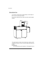
Introduction .................................................................................. 9-2
Configuring a Sorter 9-3
Maximum Capacity 9-3
Choose Binmap Menu 9-3
Modify Binmap Menu 9-6
Separation 9-8
Sort Mode 9-8
Next Bin Not Empty 9-9
Bin Groups 9-9
Logical Bin Names 9-9
Binmap Templates 9-10
Emptying Sorter Bins ................................................................ 9-10
Default Sorter Bin ...................................................................... 9-11
10 Stacker/Stapler
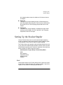
Introduction ................................................................................ 10-2
Setting Up the Stacker/Stapler ................................................. 10-3
Mode 10-3
Bin Capacities 10-4
Output Bin Names 10-6
Offset Stacking 10-6
Stapling 10-6
11 Printer-Host Connection
Introduction ................................................................................ 11-2
viii
QMS 4525 Print System Administrator’'s Guide
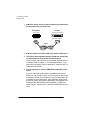
Simultaneous Interface Operation (SIO) .................................. 11-2
Emulation Sensing Processor (ESP) ........................................ 11-4
Communication Modes ..............................................................11-4
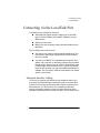
Connecting via the LocalTalk Port ........................................... 11-5
Macintosh Interface Cabling 11-5
Macintosh Printing Software .....................................................11-7
PS Executive Series Utilities 11-7
Macintosh Printer Drivers 11-8
Printer Description Files 11-9
Testing Macintosh Communication 11-10
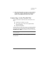
Connecting via the Parallel Port ............................................. 11-11
Testing Parallel Communication 11-13
Connecting via the Serial Port ................................................ 11-14
Printing via the Serial Port 11-16
Testing Serial Communication 11-16
Changing Serial Port Settings 11-18
PC Printing Software ............................................................... 11-20
Installing PS Executive Series Printer Utility Software 11-21
Installing a PostScript Printer Driver 11-21
PC Screen Fonts 11-22
Connecting via an Optional Network Interface ..................... 11-22
Local Console Connection ...................................................... 11-22
External SCSI-2 Port ................................................................ 11-23
A QMS Customer Support
Sources of Support ..................................................................... A-2
Your QMS Vendor A-2
Your Application Vendor A-2
Q-FAX A-2
The QMS Corporate Bulletin Board System A-3
CompuServe A-3
Internet A-3
QMS National Service A-4
Contents
ix
QMS Customer Technical Assurance (CTA) A-5
QMS World-wide Offices .............................................................A-6
B Cable Pinouts
LocalTalk ......................................................................................B-2
Serial .............................................................................................B-2
IBM PC/XT, PC/AT, and Compatible Computers .......................B-3
Centronics Parallel ......................................................................B-4
Notes to Centronics Parallel Cable Pinouts Table B-5
Dataproducts Parallel ..................................................................B-5
Local Console Connection .........................................................B-6
External SCSI-2 Port ....................................................................B-7
C Manual Notices
Manual Notice ..............................................................................C-2
FCC Compliance ..........................................................................C-2
Laser Safety .................................................................................C-3
International Notices ...................................................................C-3
Canadian Users C-3
Vfg 1046/1984 Conformity Statement C-4
Bescheininigung des Herstellers/Importeurs C-4
Declaration of Manufacturer/Importer C-4
Electronics Emissions C-4
Colophon ......................................................................................C-5
D Technical Specifications
Print Engine Specifications ........................................................D-2
Type D-2
x
QMS 4525 Print System Administrator’'s Guide
Resolution D-2
Laser Safety D-2
Printing Speed D-2
Warm-up Time D-2
Input Bins D-2
Output Bins D-3
Photoconductor D-4
Charging System D-4
Exposure System D-4
Developing System D-5
Fusing Mechanism D-5
Toner D-5
Cleaning System D-5
Power Consumption D-5
Physical Specifications .............................................................. D-6
Weight D-6
Outer Dimensions D-6
Space Requirements D-7
Room Ventilation D-7
Room Volume D-7
Acoustic Noise Emission D-7
Hard Disks ................................................................................... D-8
Print Media Specifications ......................................................... D-8
Supported Print Media D-8
Print Media Sizes and Imageable Areas D-9
Consumables ............................................................................. D-10
Toner D-10
Master Belt D-11
E
Manual Updates
Introduction ................................................................................. E-2
Hardware Requirements ............................................................. E-2
QMS Crown Technical Reference Manual Updates ................. E-3
Communications E-3
PostScript Operators E-6
CCITT Group 3 and 4 Commands E-10
Contents
xi
QMS Document Option Commands (DOC) ............................. E-11
Lineprinter Emulation E-11
LN03 Plus Emulation E-13
Document Formatting E-13
Layout Terminology E-14
Sessions ..................................................................................... E-17
What is a Session? E-17
How is a Session Used? E-18
Session Command E-20
Session Command Examples E-22
Sessions Document Finishing Terminology E-25
Document Finishing DOC Commands E-26
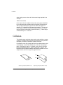
About Collation, Stapling, and Jogging .................................. E-29
Collation ..................................................................................... E-30
Chunk Collation E-31
Controlling Collation E-32
Setting Collation E-33
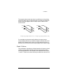
Controlling Stapling .................................................................. E-35
Using QMS DOC E-35
Stapling and Collation E-36
Controlling Jogging .................................................................. E-40
Using QMS DOC E-41
Jogging and Collation E-41
Combining Stapling with Jogging ........................................... E-45
PCL 5 Emulation Terminology ................................................. E-46
Resource E-46
Object E-47
Fonts E-48
Font Index Numbers E-48
PCL 5 Emulation DOC Commands ..........................................E-49
Index
xii
QMS 4525 Print System Administrator’'s Guide
Contents
xiii
xiv
QMS 4525 Print System Administrator’'s Guide
1
Introduction
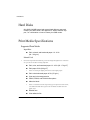
In This Chapter . . .
About this manual
Typographic conventions
Shipment contents
QMS product registration
Printer and power-up diagnostics
Print system software upgrades
About this Manual
About this Manual
This manual is designed to help the system administrator configure,
control, monitor, and maintain the QMS 4525 printer, including the
optional sorters and the stacker/stapler.
Chapter 1 - Introduction
Introduces the manual, describes typographic conventions, lists
the contents of your shipment, tells you how to register the warranty on your printer, and covers power-up diagnostics and printer
diagnostics. Also covered in this chapter are the instructions on
how to reinstall system software in case of system failure and
how to install system upgrades.
Chapter 2 - Printer Configuration
Explains how to use the keys on the printer control panel, and
how to use the menu system to control and configure the printer.
Chapter 3 - Operator Control Menu
Describes how to specify the default number of copies to print,
whether to print in duplex or tumble duplex (or neither), whether
to collate or use an optional sorter bin or the stacker/stapler, what
the default page orientation is, which paper size combination the
paper trays are set up for, and whether to use accounting.
Chapter 4 - Communications Menu
Describes the Communications menu that you use to set communications timeouts and how to configure the serial, parallel,
AppleTalk, and optional communications interfaces.
Chapter 5 - Emulations Menu
Describes the Emulations menu that you use to set the default
configurations of the PostScript, CCITT, PCL 5, HP-GL,
imPRESS, Lineprinter, and LN03 Plus emulations, and the ESP
default language.
1-2
QMS 4525 Print System Administrator's Guide
About this Manual
Chapter 6 - Special Pages and Startup Options Menus
Describes the Special Pages Header, Error, and Trailer Pages
options that you use to turn header and/or trailer page printing on
and off, to describe the input bins to print these pages from, and
to explain whether to print timing messages on the error page.
Special Pages also allows you to select the status page type.
Startup Options describes the Do Start Page, Do Sys Start, and
Do Error Handler options.
Chapter 7 - Memory Menu
Explains memory management and describes the Memory
menus that you use to set the default sizes of the following memory clients: spool buffer, PS heap, PS fonts, emulations, emulations temporary space, disk cache, and printer memory.
Chapter 8 - Engine, Miscellaneous, and Disk Operations
Menus
Explains how to use the Engine menu to set up default laser
intensity, test page, image alignment, input bin names, low toner
action, manual feed timeout, gamma correction, sorter setup, and
finisher setup (if installed). It also explains how to use the Miscellaneous menu to restore the printer to factory default settings, set
the printer name for a console system, set the control panel language, and set clock operations. The Disk Operations menu
allows you to perform file operations using the printer 's hard
disks.
Chapter 9 - Using the Sorter
Describes how to use the 20-bin and 40-bin sorters.
Chapter 10 - Using the Stacker/Stapler
Describes how to setup and use the stacker/stapler, and how to
use offset stacking.
Chapter 11 - Printer-Host Connection
Briefly explains your printer's Simultaneous Interface Operation
(SIO) and Emulation Sensing Processor (ESP) technology. Then
the chapter describes how to connect a host to the printer's
Introduction
1-3
About this Manual
LocalTalk, parallel, or serial port, and how to test communications.
Appendix A— QMS Customer Support
Lists useful telephone numbers and describes how to communicate with QMS through Q-FAX, the QMS Corporate Bulletin
Board, CompuServe, Internet, and QMS Customer Technical
Assurance.
Appendix B — Cable Pinouts
Provides the recommended pinouts for LocalTalk, serial, IBM PC/
XT, IBM PC/AT, and both Centronics and Dataproducts parallel
cables.
Appendix C- Manual Notices
Provides safety and FCC compliance statements.
Appendix D— Technical Specifications
Provides technical specifications for the printer.
Appendix E- Manual Updates
Provides updated information, such as new DOC commands or
PostScript operators, that may be created for this printer, but are
usually documented in other QMS manuals. Information in this
section will be merged into other QMS manuals as they are
revised.
1-4
QMS 4525 Print System Administrator's Guide
About this Manual
Typographic Conventions
The following typographic conventions are used throughout this manual:
Mixed-Case
Courier
Text you type, and messages and
information displayed on the console.
UPPERCASE
or
Mixed-Case
Courier
Information displayed in the printer
message window.
Mixed-Case
Italic
Courier
Variable text you type. Replace the
italicized word(s) with information
specific to your printer or computer.
bold
PostScript operators and DOS, DOC,
CCITT, VMS, and UNIX commands.
lowercase italic
Variable information in text and
command variables.
UPPERCASE
File and utility names.
↵
Press the Enter key (PC) or Return
key (Macintosh).
1RWH1RWHVFRQWDLQWLSVH[WUDLQIRUPDWLRQRULPSRUWDQW
LQIRUPDWLRQWKDWGHVHUYHVHPSKDVLVRUUHLWHUDWLRQ
2 &DXWLRQ&DXWLRQVSUHVHQWLQIRUPDWLRQWKDW\RXQHHGWRNQRZWR
DYRLGHTXLSPHQWGDPDJHRUH[WUHPHDQQR\DQFH
0 :$51,1*:DUQLQJVLQGLFDWHWKHSRVVLELOLW\RISHUVRQDOLQMXU\LID
VSHFLILFSURFHGXUHLVQRWSHUIRUPHGH[DFWO\DVGHVFULEHGLQWKH
PDQXDO
$&+781*%LWWHKDOWHQ6LHVLFKH[DNWDQGLHLP+DQGEXFK
EHVFKULHEHQH9RUJHKHQVZHLVHGDVRQVW9HUOHW]XQJVJHIDKU
EHVWHKHQNÐQQWH
Introduction
1-5
A Good Location
for Your Printer
A Good Location for Your Printer
Your QMS 4525 Print System requires an appropriate operating environment.
Physical Requirements
The location should meet the following requirements:
Be away from cooling sources, heating sources, extreme temperature changes, direct sunlight, excessive dust, and corrosive
chemicals or vapors.
Be away from any strong electromagnetic field (such as that created by an air conditioner) and excessive vibration.
Have a temperature range of 41° F (5° C) to 95° F (35° C).
Have a relative humidity range of 30% to 80%.
Be well ventilated. You should have at least 24" (600 mm) on
each side of the printer for adequate access and ventilation.
Have a room volume of at least 883 feet3 (25 meters3)
Have room ventilation of at least 442 feet3/hour (12.5 meters 3/
hour). This minimum ventilation rate, with the minimum room volume given above, holds ozone buildup within acceptable levels.
To remove heat, additional ventilation may be required.
Be as close to the host as possible: 6 feet (approximately 1.8
meters) or less for parallel communication, 25 feet (approximately
7.5 meters) or less for serial communication.
Be level and capable of supporting the printer weight:
Printer with 20-bin sorter - 1,028 lbs (approx.)
Printer with 40-bin sorter - 1,124 lbs (approx.)
U.S. Electrical Requirements
Following are U.S. electrical requirements.
1-6
Single-phase 230 V (±10%); max. 16 A; 60 Hz (±2%)
QMS 4525 Print System Administrator's Guide
Shipment Contents
The electrical connection should be direct, not via a branched
socket.
Noise-generating equipment should not be connected to the
same electrical outlet as the printer.
Shipment Contents
Your shipment contains the following:
The QMS-PS 4525 Print System
The QMS 4525 Print System User's Guide
The PS Executive Series Utilities software (on disk)
The QMS Crown Document Options Commands documentation
The QMS Crown Technical Reference documentation
The QMS Crown Remote Console User's Guide
The QMS Crown Network Notes (on disk)
The imPRESS Programmer's Guide
The HP PCL 5 Technical Reference manual
Two binders
Two bottles of toner
A warranty card
Make sure all items are included in your shipment before setting up
you printer. If any items are missing or damaged, contact your shipping company or your QMS vendor. See appendix A, “QMS Customer
Support,” for product sales and support information.
Introduction
1-7
QMS Product
Registration
QMS Product Registration
Call QMS toll-free at 1 (800) 637-8049 (US) to register your QMS
product. For contact information outside of the United States, refer to
Appendix A, “QMS Customer Support.”
Please take a few minutes to call. Your input helps us to continue
developing new products to address your changing printing needs.
Power-up Sequence Control Panel
1RWH'XULQJWKHILUVWVHFRQGVDIWHUWKHSULQWHULVWXUQHGRQ\RXFDQ
SUHVVDQ\NH\RQWKHFRQWUROSDQHORUWKHFRQVROHLIDYDLODEOHWRVHOHFWWKDW
GHYLFHDVWKH%RRW520LQSXWGHYLFH2QFHDGHYLFHLVVHOHFWHGWKHRWKHU
GHYLFHLVGLVDEOHGIRULQSXWGXULQJWKH%RRW520SURFHVV7KHGHIDXOW
%RRW520LQSXWGHYLFHLVWKHFRQWUROSDQHO
The following sequence of messages display on the control panel to
indicate the status of the BootROM:
Initializing...
This message indicates that the BootROM is initializing. When the initialization is complete, the BootROM runs a set of internal diagnostics
that take about 30 seconds to complete. As each diagnostic is started
a message is displayed identifying the diagnostic that is being executed. If an error is detected, the error code is displayed and the next
test is started. (See “Power-up Diagnostics,” later in this chapter, for
the list of diagnostics and messages.)
When the diagnostics are complete, the following message displays
in the message window:
QMS Softload x.x
Ready to boot
After this message displays, a 10 second waiting period begins. Any
key pressed during this period aborts the auto boot process and
accesses the BootROM User menu. If no key is pressed during the 10
1-8
QMS 4525 Print System Administrator's Guide
Power-up
Diagnostics
Control Panel
second period, the BootROM starts the auto boot process and the
control panel displays
Boot Systemloading
/
The bar at the end of the display keeps rotating to indicate that the
print system is downloading. When the downloading is completed,
printer initialization begins and the control panel displays
INITIALIZING
See Chapter 8, the “Control Panel—BootROM User Menu” section,
for more information on this menu.
Power-up Diagnostics Control Panel
At power-up, the print system performs the following diagnostics via
the control panel:
ROM
FLOPPY DISK controller
DRAM
Z80 - Appletalk I/F
CACHES
HARD DISK controller
TLB
PARALLEL port
NOVRAM/TOD
OPTIONAL I/O 1 Board
VIA
OPTIONAL I/O 2 Board
ENGINE duart
FLOATING POINT UNIT
As each diagnostic is started a message is displayed identifying the
diagnostic that is being executed.
Introduction
1-9
Printer Diagnostics
Console
Printer Diagnostics Console
The following diagnostic tests are available from the console:
1. DRAM
8. Parallel Port
2. CPU
9. Floppy Disk
3. Engine
10. VIA
4. Hard Disk
11. NOVRAM/TOD
5. Optional I/O
12. Perform all tests
6. AppleTalk
13. View test results
7. Serial Port
14. Return to Main Menu
These diagnostic tests are intended for use by QMS Service Engineers. See Chapter 8, the “Console—BootROM User Menu” section,
for more information on this menu. Menu selection 12, Perform all
tests, is the comprehensive self-test.
Printer Start-up Page
The printer start-up page prints each time the printer is turned on.
The page provides the following printer information:
1-10
Product name
The product name, “QMS 4525,” prints in the upper-left corner of
the page.
Printer name
The name of the printer specified with the Printer Name option of
the Administrtion/Miscellaneous menu.
Pages printed
The number of pages printed by the current controller/hard disk
configuration.
QMS 4525 Print System Administrator's Guide
Installing Print
System Software
Interface
Current configurations of the standard and optional interfaces.
Release
Printer firmware release date.
Enabling/Disabling the Start-up Page
To enable printing of the start-up page each time the printer is turned
on, set the Do Start Page option in the Administration/Startup Options
menu to Yes. To disable the start-up page, set the option to No. The
factory default setting is Yes.
Installing Print System Software
Occasionally, you may need to reinstall the printer system software for
your QMS 4525 Print System or to install a software upgrade. Print
system software for your printer is supplied on eight 3.5" 1.44 MB diskettes.
Installing system software requires copying the contents of the disks
to the printer's internal hard disk. You load the software through the
control panel, or through the parallel or LocalTalk port using PS Executive Series Utilities (see the utilities on-line help for details). The control panel loading procedure is explained in the next section.
Installing from the Control Panel
To install system software from the control panel, you need to access
the BootROM User menu and perform the following steps:
1
Turn the system off and back on again. The following message displays in the message window:
QMS Softload x.x
2
Ready to boot
Once this message displays, you have 10 seconds to press
any key.
Introduction
1-11
Installing Print
System Software
Any key pressed during this period, aborts the auto boot process
and accesses the BootROM User menu. The following message
displays:
QMS Softload x.x
Boot System
1RWH,IVHFRQGVSDVVHVEHIRUH\RXSUHVVDQ\NH\%RRW520VWDUWV
WKHDXWRERRWDQGWKH
Boot Systemloading
/
PHVVDJHGLVSOD\V<RXPXVWUHWXUQWRVWHS$OVRLI%RRW520GHWHFWV
DQHUURUZKLOHWU\LQJWRERRWWKHSULQWV\VWHPWKH%RRW5208VHUPHQX
GLVSOD\V
3
After the BootROM User menu displays, press the Previous
or Next key until the following displays in the message window:
QMS Softload x.x
4
Press the Enter key to access the Install to Disk menu and
the following displays:
Install To Disk
5
Diskette
Press the Enter key to load the software from the system diskettes. The following message displays
Install To Disk
6
Install To Disk
Target Disk 6
Press the Previous or Next keys to display other disks or
press the Enter key to select hard disk 6 as the target.
Disk 6 is the printer's internal hard disk.
1-12
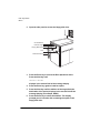
7
Open the printer's left-side door to access the floppy disk
drive.
8
Insert the first diskette into the floppy disk drive, and then
press the Enter key.
QMS 4525 Print System Administrator's Guide
Installing Print
System Software
9
When BootROM is done with the diskette, it prompts for the
next diskette by displaying
Install to Disk
Next Diskette
To continue, place the next diskette in the disk drive and press the
Enter key. This process continues until all the diskettes have been
loaded. Remember, press the Enter key after inserting each diskette.
10 You have now completed installing the system software and
are ready to boot the system.
After the contents of all the diskettes have been loaded, press the
Back key. The message window displays the following message:
QMS Softload x.x
Install To Disk
11 Press the Previous or Next key until the message window
displays:
QMS Softload x.x
Boot System
12 Press the Enter key, and then press the Previous or Next to
display
Boot System
Hard Disk
13 Press the Enter key and the following displays:
Boot System
Hard Disk 6
14 Assume that hard disk 6 is the print system's internal hard
disk. If you have any external hard disks connected, you can
cycle through them by pressing the Next key. For this example we are using the internal hard disk. Press the Enter key.
The system begins loading, and the following message displays:
Boot System
booting
/
15 At this point, DO NOT TOUCH ANY KEYS until the system
has completed loading. The slash bar on the right end keeps
rotating until the download is completed. As soon as downloading is done, the BootROM give the CPU to the downloaded image immediately. When the system rebooting and
Introduction
1-13
Installing Print
System Software
printer initialization is complete, the following message displays:
IDLE
1RWH,I\RXGRWRXFKDNH\GXULQJWKLVVWHS\RXPXVWJREDFNWRVWHS
DQGVWDUWIURPWKHUHDJDLQ
Installing From the Parallel Port
To install system software from the parallel port, follow these instructions:
1
Turn the printer off and back on again. The following message displays in the message window:
QMS Softload x.x
2
Once this message displays, you have 10 seconds to press
any key. Any key pressed during this period, aborts the auto
boot process and accesses the BootROM User menu. The
following message displays:
QMS Softload x.x
Ready to boot
Boot System
1RWH,IVHFRQGVSDVVHVEHIRUH\RXSUHVVDQ\NH\%RRW520VWDUWV
WKHDXWRERRWDQGWKH
Boot System x.x
loading
/
mHVVDJHGLVSOD\V<RXPXVWUHWXUQWRVWHS$OVRLI%RRW520GHWHFWV
DQHUURUZKLFKWU\LQJWRERRWWKHSULQWV\VWHPWKH%RRW5208VHU
PHQXGLVSOD\V
1-14
QMS 4525 Print System Administrator's Guide
Installing Print
System Software
3
After the BootROM User menu displays, press the Previous
or Next key until the following message displays
QMS Softload x.x
4
Press the Enter key to access the Install to Disk menu, and
the following displays
Install to Disk
5
Parallel
Press the Enter key to display
Install To Disk
7
Diskette
Press Next key until the following message displays:
Install To Disk
6
Install To Disk
Target Disk 6
Press the Enter key. The following message displays:
Install To Disk
Connecting....
Disk 6 is the printer's internal hard disk.
8
Go to your host system and run fstpio to send the file. Whenever the file is received, the following message displays:
Install To Disk
AFILE.TXT
/
(AFILE.TXT is the current file name.) When all files have been
sent, the following displays:
Install To Disk
Complete
1RWH7KHRSHUDWLRQLVDERUWHGZKHQHYHUDQHUURURFFXUVDQGWKH
IROORZLQJGLVSOD\V
Install To Disk
E20 disk full
(GLVNIXOOLVDQHUURUQXPEHU6HHFKDSWHUWKHo%RRW520(UURU
0HVVDJHVpVHFWLRQODWHULQWKLVPDQXDOIRUWKHOLVWRIHUURUVDQGWKHLU
UHFRYHU\
Introduction
1-15
Installing Print
System Software
9
You have now completed installing the system software and
are ready to boot the system. Press the Back key. The message window displays the following message:
QMS Softload x.x
Install To Disk
10 Press the Previous or Next key until the message window
displays:
Boot System
Hard Disk
11 Press the Enter key and the following displays:
Boot System
Hard Disk 6
12 Assume that hard disk 6 is the print system's internal hard
disk. If you have any external hard disks connected, you can
cycle through them by pressing the Next key. For this example we are using the internal hard disk. Press the Select key.
The system begins loading, and the following message displays:
Boot System
booting
/
13 At this point, DO NOT TOUCH ANY KEYS until the system
has completed loading. The slash bar on the right end keeps
rotating until the download is completed. As soon as downloading is done, the BootROM gives the CPU to the downloaded image immediately. When the system rebooting and
printer initialization is complete, the following message displays:
IDLE
1RWH,I\RXWRXFKDNH\GXULQJWKLVVWHS\RXPXVWVWDUWRYHUDWVWHS
1-16
QMS 4525 Print System Administrator's Guide
2
Printer Configuration
In This Chapter . . .
Configuring the printer
Printer status page
Using the control panel
Printer configuration
Configuration menus
Changing default settings
Configuring the
Printer
Configuring the Printer
Configuring the QMS 4525 Print System involves setting default
printer options to meet your printing requirements. Examples of common configuration options are default page size, default number of
copies, and default font. You may find that many of the factory default
configuration settings suit your needs, but you may have to change
some of them. There are four ways to change printer configuration
options:
Printer control panel
Local and remote consoles
PS Executive Series Utilities
QMS Document Option Commands
Printer Control Panel
“Using the Control Panel,” later in this chapter, describes the control
panel when the printer is on line and idle. “Printer Configuration” tells
you how to use the control panel to change the printer's default configuration settings to meet your printing requirements. After you
become familiar with using the control panel, refer to chapters 3
through 10 and the advanced status page to determine the configuration changes you want to make.
As with any network printer, one setting for any particular printer
option may not meet the needs of every user connected to the printer.
As you are configuring the printer, try to pick the setting that meets
the needs of most of the users.
Local and Remote Consoles
The QMS 4525 printer supports an optional local RS-232C console
that connects directly to a port on the printer, and 8 remote consoles
session via TCP/IP Telnet. Remote consoles behave similarly to the
local console (and control panel) as far as the information displayed
and available console commands are concerned.
2-2
QMS 4525 Print System Administrator's Guide
Configuring the
Printer
When in normal mode with display message mode enabled, status
conditions that require user intervention display on a local or remote
console . The default to display status conditions on a local console is
normal mode, the default for a remote console is silent mode.
Reverse channel is seen in normal mode, and not in silent mode.
For example, status conditions may indicate that paper is low, output
bins are full, or a paper jam has occurred. Status conditions are redisplayed each time you press the Enter key to ensure that they do not
scroll off the screen. When the problem is cleared, the following message displays:
Printer Ready
The console is a simple, line-oriented display of 24 lines of 80 characters. To list the available console commands, type ?↵ on the console
keyboard. If executing a console command results in more than a single screen of output, the display pauses every 24 lines and waits for
you to press any key to continue.
Console Modes
Regular users and the system administrator use the console for different purposes. Users check the status of their print jobs and cancel
jobs. They may also want to check available fonts or each language's
default configuration to ensure that it matches what their print jobs
expect. The system administrator uses the console more extensively
for printer configuration and file system management.
Thus, the console operates in two different modes, user and admin. In
the default user mode, only a subset of the console commands is
available. Only one console session may be in admin mode at a time.
The console prompt indicates if the console is in admin mode, user
mode, or if the system is off line.
You can use the local or remote console instead of the control panel
to change printer configuration settings. (See the QMS Crown
Remote Console User's Guide, for more information on remote console.
Printer Configuration
2-3
Configuring the
Printer
PS Executive Series Utilities
PS Executive Series Utilities, included with and designed specifically
for your printer, provides another means of communicating with your
printer. Features such as the following are provided only through the
PS Executive Series Utilities:
Printer drivers, including a Windows 3.x driver
Screen fonts for Macintosh users
Screen printing for PC users
Printer naming
Font and directory listings
The PS Executive Series Utilities on-line help gives complete instructions for installing and using the software.
QMS Document Option Commands (DOC)
Printer configuration settings can be changed by appending QMS
Document Option Commands (DOC) to the beginning of a print job.
On some networks, you can set up print queues that automatically
insert DOC commands that select specific printer features for print
jobs sent via each queue.
For instance, you might set up a queue called “collate” which automatically sends DOC commands that cause the attached print job to
be collated. Another queue, called “booklet,” might print the attached
job in booklet format with pages collated. After printing the job, the
printer automatically reverts to its default configuration that was set
via the control panel or a console. (See the QMS Crown Document
Option Commands manual, for detailed information about QMS DOC
commands.
Supported QMS DOC Commands
The following is a list of QMS Document Option Commands supported by the QMS 4525 printer (the optional emulations may not be
on your printer). For a complete list of DOC commands and more
2-4
QMS 4525 Print System Administrator's Guide
Configuring the
Printer
information on these commands, see the QMS Crown Document
Option Commands manual.
1RWH8SGDWHG,QIRUPDWLRQRQ'2&FRPPDQGVWKDWKDVQRW\HWEHHQ
LQFOXGHGLQRWKHUPDQXDOVLVLQFOXGHGLQDSSHQGL[(o0DQXDO8SGDWHVpRI
WKH6\VWHP$GPLQLVWUDWRUnV*XLGH7KHVHFRPPDQGVDUHSUHIL[HGZLWKDQ
o*p
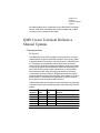
Command Summary
The following is a list of QMS Document Option Commands.
Header/Trailer
Function
Print document creator
Print creation date and time
Print copyright statement
Print current date
Print header page
Print document host
Print document owner
Print document title
Print trailer page
Print routing information
Print version and revision
Command
%%Creator:
%%CreationDate:
%%CopyRight:
%%Date:
%%IncludeFeature: header
%%Host:
%%For:
%%Title:
%%IncludeFeature: trailer
%%Routing:
%%Version:
Printer
Function
Booklet printing
Collate document
Duplex print
Logical margins
Logical page orientation
Logical page size
New layout
Number up printing
Offset logical page
Print background images
Print borders
Printer Configuration
Command
%%IncludeFeature: booklet
%%IncludeFeature: collate
%%IncludeFeature: duplex
%%IncludeFeature: margins
%%IncludeFeature: pageorientation
%%IncludeFeature: pagesize
%%IncludeFeature: newlayout
%%IncludeFeature: pagegrid
%%IncludeFeature: pageoffsets
%%IncludeFeature: background
%%IncludeFeature: border
2-5
Configuring the
Printer
Print page range
Scale logical page
Select emulation
Select number of copies
Select orientation
Select output bins
Select paper
Enable stapling
Enable offset stacking
%%IncludeFeature: pagerange
%%IncludeFeature: pagescaling
%%IncludeFeature: emulation
%%IncludeFeature: numcopies
%%IncludeFeature: orientation
%%IncludeFeature: output
%%IncludeFeature: input
%%IncludeFeature: staple
%%IncludeFeature: offset
HP-GL Emulation
Function
Expand plot
Scale the image
Select enhanced resolution
Select original paper size
Select pen width and color
Select plotter
Shift the origin
Reverse image
Command
%%IncludeFeature: expand
%%IncludeFeature: scaling
%%IncludeFeature: enhanced
%%IncludeFeature: size
%%IncludeFeature: pen
%%IncludeFeature: plotter
%%IncludeFeature: origin
%%IncludeFeature: reverse
HP PCL 5 Emulation
Function
*Disable scalable
*Install object
*Remove object
*Remove resource
*Select font
*Select font ID
*Select symbol set
*Set carriage return
*Set line feed
*Set lines per page
*Set point size
*Resource
Reset to default
2-6
Command
%%IncludeFeature: scalablefonts
%%IncludeFeature: install
%%IncludeFeature: remove
%%IncludeFeature: removeresource
%%IncludeFeature: font
%%IncludeFeature: fontid
%%IncludeFeature: fontindex
%%IncludeFeature: symbolset
%%IncludeFeature: criscrlf
%%IncludeFeature: lfiscrlf
%%IncludeFeature: linesperpage
%%IncludeFeature: pointsize
%%IncludeFeature: resource
%%IncludeFeature: reset
QMS 4525 Print System Administrator's Guide
Configuring the
Printer
Lineprinter Emulation
Function
Font selection
Point size
Character map
Line numbering
Tab spacing
Line feeds
Carriage returns
Form feeds
Orientation
Autowrap
Lines per page
Margins
Command
%%IncludeFeature: font
%%IncludeFeature: pointsize
%%IncludeFeature: map
%%IncludeFeature: number
%%IncludeFeature: tabs
%%IncludeFeature: lfiscrlf
%%IncludeFeature: criscrlf
%%IncludeFeature: ffiscrff
%%IncludeFeature: lporientation
%%IncludeFeature: autowrap
%%IncludeFeature: linesperpage
%%IncludeFeature: lpmargins
LN03 Plus Emulation
Function
Include product identification
Move the X origin
Move the Y origin
Print Orientation
Reset override to default
Set default paper size
Set paper size override
Wrap long lines
Command
%%IncludeFeature: product
%%IncludeFeature: xorigin
%%IncludeFeature: yorigin
%%IncludeFeature: orient
%%IncludeFeature: reset_override
%%IncludeFeature: paper_size
%%IncludeFeature: paper_size_override
%%IncludeFeature: autowrap
PostScript Emulation
Function
Select PostScript level
Default dither
Command
%%IncludeFeature: languagelevel
%%IncludeFeature: defaultdither
Session Commands
Function
*Session
*Start New Layout
Printer Configuration
Command
%%Session:
%%IncludeFeature: newlayout
2-7
Configuring the
Printer
Supported CCITT Group 3 and 4 Commands
Reverse bits
Set end of block
Set data compression
Set dpi
Set encoded byte flag
Start decompression
Set image position
Set image size
Invert image
End print job
Set line end
Eject page
Set rotation
%%BitReverse
%%BlockEnd
%%Compression
%%DPI
%%EBA
%%ImageData
%%ImagePosition
%%ImageSize
%%InvertImage
%%JobEnd
%%LineEnd
%%PageEnd
%%Rotation
Deciding Which Configuration Method to Use
Some configuration options can be changed only from the control
panel menu system, some can be changed only from a local or
remote console, some can be changed only with QMS DOC commands, and, of course, some options can be changed with any of
these methods.
It makes no difference whether you change printer default configuration settings via the control panel or via a local or remote console, so
use whichever method is most convenient for you. Just remember
that the hierarchy of commands is usually:
Application
Selections (such as page size, orientation, duplexing, collating)
you make when printing a file from your application override any
network commands or printer configuration settings that do the
same things. This gives you more control over your print job and
your selections affect only that print job. Use your application to
control your print job whenever possible.
2-8
Network Print Commands
QMS 4525 Print System Administrator's Guide
Configuring the
Printer
Network print commands usually affect only an individual print
job. However, when automatically sent from a print queue, network print commands are added to every job sent from that print
queue. Network print commands may or may not override application commands, depending on the way the queue is set up.
See your system administrator.
QMS DOC Commands
Selections (such as page size, orientation, duplexing, collating)
you make by prepending QMS Document Option Commands
(DOC) to the beginning of your print job, or that are automatically
prepended to jobs sent from a network print queue, affect only
that print job. This gives you control over your print job and your
selections affect only that print job.
Control Panel
Changes made via the control panel affect the power-up default
configuration of the printer, and therefore affect all subsequent
print jobs unless overridden by your application or DOC commands. Printer default configuration settings should be set to support the most common requirements that are placed on the
printer.
PS Executive Series Utilities
Changes made from PS Executive Series Utilities also affect the
power-up default configuration of the printer, and therefore affect
all subsequent print jobs unless overridden by your application or
DOC commands.
Local or Remote Console
Changes made via local or remote consoles also affect the
power-up default configuration of the printer, and therefore affect
all subsequent print jobs unless overridden by your application or
DOC commands.
Printer Configuration
2-9
Printer Status Page
Printer Status Page
Before you start configuring the printer, you should have a status
page so you can see the current default settings of many of the printer
configuration options.
Printing Status Pages
Printing a status page is a two-step procedure: Identify the type of
status page to print and then print it.
Identifying Status Page Type
There are two types of status pages available:
Standard—This one page document lists printer identification
information, current memory configuration, timeouts, communication settings, input buffer sizes, and available fonts.
Advanced—This document, which can be five or more pages,
contains the same information as the standard status page as
well as configuration menu settings, fonts, and downloaded emulations.
Printing a Status Page
After you have identified the type of status page to print, select that
status page type in the Administration / Special Pages / Status Page
Type menu. Then you can send the status page to print. Make sure
the printer is on line and idle, and press the Status Page key.
Using the Control Panel
The QMS 4525 Print System provides a full-featured control panel
that makes it easy to configure and control the printer. The printer
also uses the control panel to communicate with you by providing
messages about its status, including any conditions that require your
attention. These messages can be displayed in English, French, or
2-10
QMS 4525 Print System Administrator's Guide
Using the Control
Panel
German. The control panel layout is uncluttered, and the keys are
large and clearly marked.
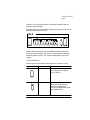
When the printer is on line and idle (ready to accept a print job), this is
what the control panel looks like
IDLE
Many of the control panel keys have different functions when the
printer is off line and when it is on line. For descriptions of the keys
when the printer is off line, see “Printer Configuration” later in this
chapter.
Control Panel Keys
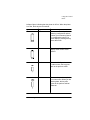
These are the keys that are functional when the printer is on line:
Symbol
Key Name
Function
Continue
Continues the current print job
after a paper jam or engine
error is cleared.
Status Page
Prints a status page which
shows the printer's current
status and configuration,
including available paper sizes
and installed fonts.
Printer Configuration
2-11
Using the Control
Panel
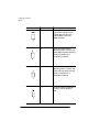
Line
Toggles the printer between on
line and off line. The two lights
above the key indicate the
current status.
Cancel
Cancels all jobs that are
currently being processed or
printed, or sends an end-of-job
indicator to a print job waiting for
incoming data. Print jobs that
are spooled begin printing after
current jobs are cancelled or
ended.
Message Display
The control panel message display is a single-line display with two
fields. When you are using the control panel to change printer configuration settings, a menu name or option name displays in the first field
and a menu or option name or option setting displays in the second
field. Printer status messages and error messages are also displayed.
Printer Configuration
To configure the printer via the control panel, place it off line by pressing the Line key. The On indicator above the key goes out and the Off
2-12
QMS 4525 Print System Administrator's Guide
Using the Control
Panel
indicator lights, indicating that the printer is off line. When the printer
is off line, these keys are functional:
Symbol
Key Name
Function
Enter
Works as an Enter key when
selecting configuration options
or when you are entering data in
the configuration menus. If a
menu displays, pressing this key
enters that menu.
Clear
Clears input data from the
display at the current cursor
position.
Back
Enters the Configuration menu.
In other menus, this key goes
back to the previous menu.
Previous
Moves to the previous option in
the current menu. When you are
entering data, this key also
cycles to the previous ordinal
character.
Printer Configuration
2-13
Using the Control
Panel
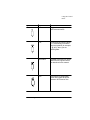
Symbol
2-14
Key Name
Function
Next
Moves to the next option in the
current menu. When you are
entering data, this key also
cycles forward to the next
ordinal character.
Left
Moves the cursor left one
character position. Use this key
and the Right key when entering
a string in response to a
configuration question.
Right
Moves the cursor right one
character position. Use this key
and the Left key when entering
a string in response to a
configuration question.
A..Z
Cycles through the characters A
to Z when you are entering
data.
QMS 4525 Print System Administrator's Guide
Using the Control
Panel
Symbol
Key Name
Function
A/a
Toggles between uppercase
and lowercase letters.
0..9,..
Cycles through numeric values
0 - 9, followed by punctuation
keys and symbols (for example,
!, @, #, $), when you are
entering data.
Multi Value
Intended to be used only by the
QMS Service Engineer and is
not described in this manual.
Line
Exits from the Configuration
menu and toggles the printer
between off line and on line.
Printer Configuration
2-15
Configuration
Menu
Configuration Menu
The printer's configuration menu options are divided into two main
menus: Operator Control and Administration.
Operator Control menu
The Operator Control menu configures the number of copies,
inputbins, outputbins, chain inputbins, duplex, tumble duplex, collation, page orientation, job accounting settings.
Administration menu
The Administration menu controls default configuration options
through the Communications, Emulations, Special Pages, Startup
Options, Memory, Engine Setup, Miscellaneous, and Disk Operations menus.
Accessing the Configuration Menu System
Once the printer is off line, press the Back key to enter the Configuration menu.
The configuration menu displays as two fields of text on the control
panel. The first field (left) shows the current menu (Configuration in
this case) and the second field (right) shows the Operator Control
menu. Here’s how the control panel looks at this point.
CONFIGURATION
2-16
OPERATOR CONTROL
QMS 4525 Print System Administrator's Guide
Configuration
Menu
Accessing the Operator Control Menu
If you want to change option settings in the Operator Control menu,
press the Enter key to access the menu. The menu name and the first
option in the menu are displayed:
OPERATOR CONTROL
COPIES
To access a menu or option in the Operator Control menu, use the
Next and Previous keys to display it in the second field and press the
Enter key. If the selected item is another menu, the menu name and
the first option in that menu display. If the selected item is a configuration option, the option displays in the first field and a list of possible
settings displays in the second field. If the option requires you to enter
text (operator password, for instance) the current text is displayed in
the second field with the first character underlined. Use the A..Z key
to cycle through the alphabet and the Left/Right keys to move
between characters in the text.
Accessing the Administration Menu
If you want to change option settings in the Administration menu
(starting at the point shown in control panel illustration above), press
the Next key to advance to the Administration menu, and press the
Enter key to access it. The menu name and the first option in the
menu are displayed:
ADMINISTRATION
COMMUNICATIONS
To access a menu or option in the Administration menu, use the Next
and Previous keys to display it in the second field and press the Enter
key. If the selected item is another menu, the menu name and the first
option in that menu display. If the selected item is a configuration
option, the option displays in the first field and a list of possible settings displays in the second field. If the option requires you to enter
text (printer name, for instance) the current text is displayed in the
second field with the first character underlined. Use the A..Z key to
cycle through the alphabet and the Left/Right keys to move between
characters in the text.
Printer Configuration
2-17
Changing Default
Settings
Changing Default Settings
There are two types of printer menu options: those that require
choosing from a set of possible pre-defined values and those that
require entering alphanumeric information.
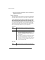
An Enumerated List of Values
If an option has an enumerated list of possible values, they display in
the second field of the message window. Here we use the Administration / Communications / Serial / Baud Rate option as an example of
choosing values from an enumerated list:
1
With the printer idle, press the Line key to place the printer
off line.
2
Press the Back key to enter the Configuration menu:
CONFIGURATION
3
Press the Next to advance to the Administration menu:
CONFIGURATION
4
MODE
Press the Next key until the Baud Rate menu displays in the
second field of the message display:
SERIAL
2-18
SERIAL
Press the Enter key to enter the Serial menu:
SERIAL
8
TIMEOUTS
Press the Next key until the Serial menu displays in the second field:
COMMUNICATIONS
7
COMMUNICATIONS
Press the Enter key to enter the Communications menu:
COMMUNICATIONS
6
ADMINISTRATION
Press the Enter key to enter the Administration menu:
ADMINISTRATION
5
OPERATOR CONTROL
BAUD RATE
QMS 4525 Print System Administrator's Guide
Changing Default
Settings
9
Press the Enter key to enter the Baud Rate menu. The first
choice in the set of baud rate values displays in the second
field. This value is also the current default setting.
BAUD RATE
9600
10 Press the Next key until the value you want (for example,
2400) displays:
BAUD RATE
2400
11 Press the Enter key. A confirmation message displays for a
few seconds:
BAUD RATE CHANGED 2400
12 Then, the option's name displays:
SERIAL
BAUD RATE
You have now changed the baud rate to 2400. The change does not
take effect until you place the printer on line. Before doing so, review
the ”Saving Printer Configuration Changes” section, later in this chapter.
Alphanumeric Strings
If an option is an alphanumeric string, you enter the string one character at a time. You use the 0..9,%..key to cycle through the numbers,
and the A..Z key to cycle through the characters. Use the A/a key to
change the case of characters entered with the A..Z key.
Printer Configuration
2-19
Changing Default
Settings
1RWH7KHIROORZLQJFKDUDFWHUVDSSHDUDVEORFNVRQWKHFRQWUROSDQHODQG
WKHFRQVROHZKHQ\RXHQWHURUFKDQJHQRQDOSKDFKDUDFWHUVXVLQJWKH
NH\7KH4063ULQW6\VWHPVKRZVWKHIROORZLQJQRQVXSSRUWHG
FKDUDFWHUVDVEORFNV
8VHWKHSUHYLRXVDQGQH[WFKDUDFWHUVVKRZQLQWKHQH[WSDUDJUDSKWR
GHWHUPLQHZKDWFKDUDFWHUWKHEORFNUHSUHVHQWV
Block-represented
Character
Previous Character
Next Character
space
z
0
$
#
%
^
]
-
-
^
‘
~
}
A
Alphanumeric String Example
The Copies option in the Operator Control menu is an example of an
alphanumeric string. The following instructions show how to change
an alphanumeric string:
1
With the printer idle, press the Line key to place the printer
off line.
2
Press the Back key. The following message displays in the
message display:
CONFIGURATION
3
Press the Enter key. This opens the Operator Control menu,
which displays in the first field of the message display:
OPERATOR CONTROL
4
COPIES
Press the Enter key again to display the current setting (the
default copy count is 1):
COPIES
2-20
OPERATOR CONTROL
001
QMS 4525 Print System Administrator's Guide
Changing Default
Settings
5
Notice that the first digit is highlighted. You may select any
number of copies up to 1000. For this example, we are setting the copy count to 159.
6
Press the Next key once. The first digit changes from 0 to 1.
Press the Enter key.
7
The second digit is now highlighted. Press the Next key until
the second digit changes to 5. Press the Enter key.
8
The third digit is now highlighted. Press the Previous key
until the last digit changes from 1 to 9:
COPIES
9
159
Press the Enter key. The message display momentarily confirms the change you have made:
COPIES CHANGED TO 159
Then the message display displays the option's name again.
OPERATOR CONTROL
COPIES
You have now changed the copy count to 159 copies per print job.
The change does not take effect until you place the printer on line.
Before doing so, review the next section, “Saving Printer Configuration Changes.”
Saving Configuration Changes
Before the printer can accept print jobs with configuration changes,
the changes must be saved.
Example
To save configuration changes, press the control panel keys in the
order shown in the following example. The printer responds by displaying a message in the message window.
Whenever you make a change to most printer menu options, the
printer prompts you to save the change when you place the printer on
Printer Configuration
2-21
Changing Default
Settings
line. Saving a menu change means that the new value of the option is
recorded and stored in the printer's memory. Follow these steps to
save your change to the Baud Rates and Copies options:
1
Press the Line key or the Back key to exit from the menu and
be prompted to save your change (Line key) or return to the
previous menu (Back key). The following message displays:
SAVE CHANGES?
NO
2
Press the Next key to advance to the Save Changes/Yes
option. (YES displays in the second field), and then press the
Enter key. The printer saves your changes and returns to
idle.
3
Press the Line key turn on the On indicator and enable the
printer to accept and print new jobs.
1RWH6RPH$GPLQLVWUDWLRQPHQXFKDQJHVUHTXLUHWKDWWKHSULQWHUEH
UHVWDUWHGEHIRUHWKH\WDNHHIIHFW6RPHFKDQJHVUHVWDUWWKHSULQWHU
DXWRPDWLFDOO\ZKLOHRWKHUVGLVSOD\WKHPHVVDJH REBOOT NOW? LQWKH
FRQWUROSDQHOPHVVDJHZLQGRZ,IWKLVPHVVDJHDSSHDUVVHOHFWYESWR
UHVWDUWWKHSULQWHUDQGKDYHWKHFKDQJHVWDNHHIIHFWLPPHGLDWHO\RUVHOHFW
NOWRZDLWXQWLO\RXPDQXDOO\UHVWDUWWKHSULQWHUEHIRUHWKHFKDQJHVWDNH
HIIHFW
2-22
QMS 4525 Print System Administrator's Guide
3
Operator Control and
Installation Menus
In This Chapter . . .
Copies
Duplex and tumble duplex
Collation
Orientation
Input bins, output bins, chain input bins
Accounting
Password protection
The Operator
Control Menu
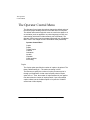
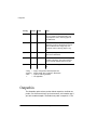
The Operator Control Menu
The Operator Control menu has options that set the default values of
the various paper handling features of the QMS 4525 Print System.
The default values set through this menu are used in the absence of
an emulation (such as application or printer language) or DOC command setting (which also includes network print commands). The
Operator Control menu may be password-protected (see “Installation
Menu” later in this chapter for more information about passwords).
Operator Control Menu
Copies
Duplex
Tumble Duplex
Collation
Orientation
Inputbin
Outputbin
Chain Inputbins
Accounting
Copies
The Copies option specifies the number of copies to be printed. The
factory default setting is 1. The maximum setting is 1000.
The best way to specify the number of copies you want to print is
through your application. In that case, keep the printer's Copies
option set to 1. Then, the number of copies selected in your application determines the number of copies printed. If you want multiple
copies collated, set the Collation option to On (see the “Collation”
section later in this chapter).
3-2
QMS 4525 Print System Administrator's Guide
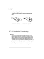
Duplex
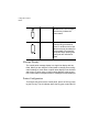
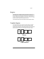
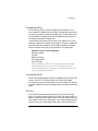
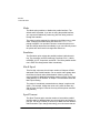
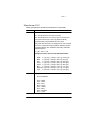
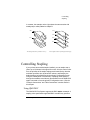
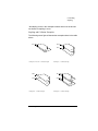
Duplex
The Duplex option enables printing on both sides of a sheet. The
default setting is Off. Unless you want all jobs printed in duplex mode,
do not change the default setting. The best way to specify duplex
printing is through your application. In that case, use it to turn duplex
mode On and Off, and leave this option set to Off.
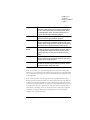
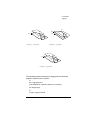
The illustration below shows the duplex and tumble duplex options.
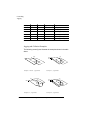
Tumble Duplex
The Tumble Duplex option controls the default settings for duplex
mode. When using tumble duplex, both the Duplex and Tumble
Duplex options must be On. The default setting is Off. The illustration
below shows the difference between duplex and tumble duplex.
Side 1
Side 2
Portrait
Side 1
Side 2
Landscape
DUPLEX
Side 1
Side 2
Portrait
Side 1
Side 2
Landscape
TUMBLE DUPLEX
Operator Control and Installation Menus
3-3
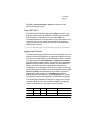
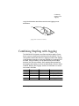
Collation
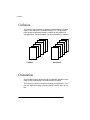
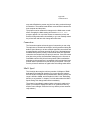
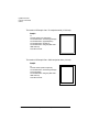
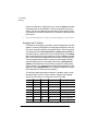
Collation
The Collation option enables or disables collated stacking of multiple
copies in the output bins. The default setting is On. The illustration
below shows the difference between collation on and collation off.
See appendix E, “Manual Updates,” for more information on collation.
Collated
Uncollated
Orientation
The Orientation option selects portrait or landscape orientation of the
image on the physical page. The default setting is Portrait.
The best way to specify orientation is through your application. If you
use your application's page orientation feature, set this option to Portrait.
3-4
QMS 4525 Print System Administrator's Guide
Orientation
1RWH7KHRQO\ZD\WRVHWOLQHSULQWHURULHQWDWLRQLVYLDWKH/LQHSULQWHU
2ULHQWDWLRQRSWLRQRQWKH$GPLQLVWUDWLRQ(PXODWLRQV/LQHSULQWHUPHQXRU
YLDWKH/32ULHQWDWLRQ'2&FRPPDQGDYDLODEOHLQWKH/LQHSULQWHUHPXODWLRQ
Operator Control and Installation Menus
3-5
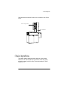
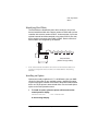
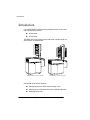
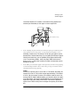
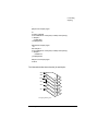
Inputbin
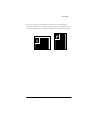
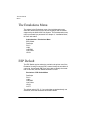
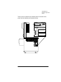
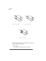
Inputbin
The Inputbin option selects the Upper or Lower input bin as the
default input bin. The illustration below shows the locations of the
input bins. The default setting is lower.
8SSHU,QSXW%LQ
3DSHU
&RPSDUWPHQW
/RZHU,QSXW%LQ
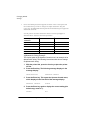
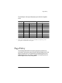
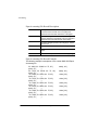
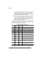
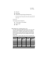
Print Media Sizes and Imageable Areas
Your printer supports paper and transparencies in eight sizes. Each
size has a certain imageable area, the maximum area capable of
being printed on. It is subject to both hardware limits (the physical
page size and the margins required by the printer engine).
3-6
QMS 4525 Print System Administrator's Guide
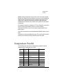
Page Policy
The following are the supported paper types and their imageable
areas:
Paper type Inches
Page Size
Millimeters
Imageable Area Page Size
Imageable Area
Letter
8.5 x 11.0
8.19 x 10.66
216 x 279
208 x 271
Legal large
8.5 x 14.0
8.19 x 13.69
216 x 356
208 x 348
A4
8.3 x 11.7
7.95 x 11.37
210 x 297
202 x 289
Quarto
8.0 x 10.0
7.67 x 9.68
203 x 254
195 x 246
Commercial 8.3 x 10.6
7.95 x 10 .31
210 x 270
202 x 262
Foolscap
8.0 x 13.0
7.67 x 12.67
203 x 330
195 x 322
Folio
8.3 x 13.0
7.95 x 12.67
210 x 330
202 x 322
Legal Small 8.5 x 13.0
8.19 x 12.67
216 x 330
208 x 322
1RWH,IDUHTXHVWHGSDSHUVL]HLVQRWLQVWDOOHGLQWKHSULQWHU\RXDUH
SURPSWHGWRLQVWDOOWKHFRUUHFWSDSHU
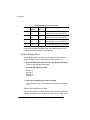
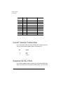
Page Policy
The following QMS 4525 Print System page policy specifies the
action that is to be taken when a print job requests a paper size. Each
page of the print job is to be printed from a selected input bin on a
selected paper size. Your printer is capable of recognizing only two
different paper sizes for any configuration.
Operator Control and Installation Menus
3-7
Outputbin
Config
Present
Chain
Policy
no
x
no
Print on whatever paper is in the desired
bin. If no paper is in the desired bin, stop
and prompt the user to load any paper in
the desired bin.
no
x
yes
Print from the desired bin if it has paper.
Otherwise, print from the other bin if it has
paper. If both bins are empty, stop and
prompt the user to load any paper in any
bin.
yes
no
no
Stop and prompt you to load the desired
paper in the desired bin.
yes
no
yes
Print from the other bin if the desired paper
is loaded. Otherwise, stop and prompt the
user to load the desired paper in any bin.
yes
yes
x
Print on the desired paper from the desired
bin.
*config
*present
*chain
x
=
=
=
=
engine configured for desired paper size
desired paper size is present in desired bin
input bin chaining enabled
not applicable
Outputbin
The Outputbin option selects, as the default output bin, the Side output bin, one of the sorter bins if you have a sorter, or the stacker tray if
you have a stacker/stapler. The default out pubin is output bin 1.The
3-8
QMS 4525 Print System Administrator's Guide
Chain Inputbins
illustration below shows the locations of the output bins on a 20-bin
sorter.
6RUWHU2XWSXW%LQV
6LGH2XWSXW%LQ
Chain Inputbins
The Chain Inputbins option specifies whether or not the printer
switches to the other inputbin (if it contains the same size paper)
when the current inputbin is empty. The default setting for Chain
Inputbin is Off.
Operator Control and Installation Menus
3-9
Accounting
Accounting
The following three types of accounting are available with your QMS
4525 Print System:
Crown Accounting
If your printer is connected to a host, standard QMS Crown
accounting is available to you on the QMS 4525 Print System.
Standard Network Management Systems (SNMP)
If your printer is connected to a network via TCP/IP, you have
standard QMS Crown accounting and SNMP accounting (the
standard system for managing the network provides). See the
TCP/IP Protocol Option User's Guide, for more information on
SNMP.
TCP/IP Accounting/Reverse Channel
If your QMS 4525 is connected to a network with a TCP/IP interface, you have standard QMS Crown accounting, SNMP accounting, and TCP/IP Accounting and Reverse Channel. See the TCP/
IP Protocol Option User's Guide, for more information on TCP/IP
accounting.
Crown Accounting
Crown accounting is a tool to help you keep track of resource utilization for the QMS 4525. Typically, the number of sheets of each paper
type supported is the most common resource for which Crown printer
accounting is kept. The system administrator is interested in knowing
the paper utilization per user, the time consumed servicing the print
jobs per user, connectivity options, frequency of jams, times of peak
usage, number, complexity, and size of jobs per user, and features
and options most commonly used (duplexing, finishing, and other
options).
3-10
QMS 4525 Print System Administrator's Guide
Accounting
Accounting Menu
The Accounting menu is under the Operator Control Menu. This
menu enables or disables job accounting, allocates disk space when
accounting is enabled, resets accounting, lets you store job accounting information in a single job file or in multiple files, and copies the
accounting information to floppy disk.
Job accounting information can be stored in a single file if it can be
retrieved using the file transfer protocol (ftp) on your host. Otherwise,
the selected job accounting file size should be spread into several
files so that each of the files (or segments) fits on a floppy disk.
Operator Control / Accounting Menu
Accounting Mode
File Size
Reset Accounting
File Segmentation
Copy to Floppy
1RWH7RIDFLOLWDWHRSHUDWLRQRIWKH$FFRXQWLQJRSWLRQVLWLVKLJKO\
UHFRPPHQGHGWKDW\RXXVHDORFDOFRQVROH$YWWHUPLQDO
FRQQHFWHGGLUHFWO\WRWKHFRQVROHSRUWRQWKHSULQWHULQWHUIDFHSDQHO
XVLQJDVHULDO56&FRQQHFWRU
Accounting Mode
The Accounting Mode option enables or disables job accounting. The
range is On or Off. The default value is Off. When you disable
accounting and the accounting file(s) is (are) not empty, they remain
untouched. However, if they are empty, they are removed to save disk
space.
File Size
The File Size option allocates disk space for the Job Accounting
file(s). The range of values is 50 KB to 10 MB. The default value is 1
MB. If the selected value is greater than the current value, the file size
is increased to reserve the extra space. If the value is smaller than the
current file size, any unnecessary (still empty) Job Accounting files
Operator Control and Installation Menus
3-11
Accounting
are removed. If only one file is used and it is not empty, it cannot be
shrunk.
If no accounting information exists in the system when shrinking the
usage, the Job Accounting file(s) is (are) recreated using the new
size. The printer does not ask for confirmation for this operation. It
takes effect immediately.
The amount of space required for each job can vary between 200 and
250 bytes so you can store information for 4000 to 5000 jobs for each
1 MB in the Job Accounting file.
Reset Accounting
The Reset Accounting option erases the Accounting files and
re-creates them using the current file size. If this operation is selected
when Accounting is disabled, the files are removed but not recreated,
thus saving disk space. The range of values is Yes or No. The default
value is No.
This operation is also available as the resetaccount command for the
admin user in the local or remote consoles. See the Remote Console
User's Guide, for more information on the resetaccount command.
Whenever the job file(s) are more than 80% full, the following message is displayed on the control panel, local, and remote consoles
xxxxxxxx FILE xxx% FULL
(xxx% represents the percentage full in increments of 5%–85%, 90%,
and 95%.) This is an appropriate time to copy these files to floppies or
to transfer them to your host computer using ftp if it is available to you.
Then use the option to reset the accounting files to empty after they
are copied to a floppy or to a host.
When the file is 100% full, the
xxx FILE IS FULL
message displays.
3-12
QMS 4525 Print System Administrator's Guide
Accounting
1RWH:KHQDFFRXQWLQJLVHQDEOHGDQGWKH-RE$FFRXQWLQJILOHVLVDUH
IXOOQRIXUWKHUSULQWMREVZLOOEHDFFHSWHGE\WKHSULQWHUXQWLO5HVHW
$FFRXQWLQJLVVHOHFWHGRUXQWLO$FFRXQWLQJLVGLVDEOHG,I\RXGLVDEOH
$FFRXQWLQJDWWKLVWLPHQRMRELQIRUPDWLRQZLOOEHVWRUHGIURPWKDWSRLQW
RQ<RXFDQUHWULHYH\RXUDFFRXQWLQJILOHVZKLOHWKH\DUHIXOODQGWKHQGRWKH
5HVHW$FFRXQWLQJRSHUDWLRQ+RZHYHUWRDYRLGGHOD\LQJMREVEHLQJVHQWWR
WKHSULQWHULWLVDGYLVDEOHWRSHUIRUPWKHUHWULHYHUHVHWRSHUDWLRQVEHIRUH
WKH-RE$FFRXQWLQJILOHVILOOXS
File Segmentation
This is used to indicate to the system whether to store the accounting
information in a single file or in multiple files. If a single file is used, its
size will be equal to the File Size value described earlier in this section. The file name will be ACC1.JOB.
If multiple files are selected, their combined size will be equal to the
File Size value described earlier in this section. Each file will be 1 MB,
with the exception of the last file. The Job file names will be
ACC1.JOB, ACC2.JOB, and so on.
Copy to Floppy
This option copies each of the Accounting files to the floppy. Make
sure that the floppy disk you use is formatted for DOS compatibility.
The last selection copies the auxiliary accounting files to the floppy
disk. These files are ACC.STA, ACC.PAP, ACC.DIC. These files are
described later in this chapter. Additionally, there is an entry for each
of the possible Job Accounting files (ACC1.JOB through
ACC10.JOB). Not all will exist, so you need to copy only the ones that
are necessary. For example, if you choose a single file, only
ACC1.JOB will need to be copied. If multiple files are used, the size
chosen will determine which Accounting Job files need to be copied.
For example, if the size is 7.5 MB, then you will need to copy files
ACC1.JOB through ACC8.JOB. If you attempt to copy a non existent
file, a FILE NOT FOUND error displays.
Operator Control and Installation Menus
3-13
Accounting
How Crown Accounting Works
As jobs are printed on the QMS 4525 printer, the system collects
information about different job parameters in relation to the jobs.
When each job completes, the printer stores an entry for the job in the
Job Accounting file(s).
2 &DXWLRQ'RQRWWXUQWKHSULQWHURIIZKLOHWKHGLVNLVEHLQJDFFHVVHG'RLQJVR
PD\FDXVHLQFRQVLVWHQFLHVLQWKHLQIRUPDWLRQVWRUHG
The following accounting files are stored in the path DSK6:/
admin:
Job Accounting File (ACCx.JOB)
This is the main accounting file (it may be a single or multiple
files). When each job completes, the printer stores an entry for
the job in this file. (x is the number of the Job Accounting file
when multiple files are used.) Information in this file is kept intact
after the printer is turned off and back on again.
Paper Accounting File (ACC.PAP)
This file contains descriptions of the paper types supported on
the QMS 4525 Print System.
Status Accounting File (ACC.STA)
This file stores configuration information about accounting.
Dictionary File (ACC.DIC)
This file contains documentation about accounting and a description of the fields used in the other accounting files.
2 &DXWLRQ$OOWKHDFFRXQWLQJILOHVDUHVWRUHGLQ$6&,,IRUPDWWRPDNHLW
VLPSOHUWRXVHWKHLQIRUPDWLRQLQGLIIHUHQWHQYLURQPHQWVDIWHULWLVUHWULHYHG
IURPWKHSULQWHU
VKDUGGLVN
3-14
QMS 4525 Print System Administrator's Guide
Accounting
Accounting File Format Description
The ASCII file format chosen allows the file to be extended by tagging
each field in each record in each of the accounting files. New fields
can be added by creating new tag identifiers for the new fields.
This allows backward compatibility for existing filters when the
accounting files evolve in future versions. A version field is included to
identify the supported fields as the system evolves.
The following format is the same for the three file types:
Tag Identifiers
In order to minimize disk space, the tag identifiers are three digit
numbers instead of names. The Dictionary file provides the field
names associated with each tag identifier.
String Information
String information is stored inside braces (for example, {this is a
string}). This allows spaces within strings and stores only the necessary characters of a string value. String fields for which no
value is specified are stored as {}, instead of using blanks or the
maximum field size.
New Records
New records are separated by a <CR> character. This separator
increases the file readability.
Separators
A typical record in any of the accounting files is a sequence of
pairs of tag identifiers and field values separated by commas. The
tag identifier and field value are separated by a colon.
The following is an example of the format of an accounting file record:
1: 3, 2:{this is a string}, <CR>
In this example, the record has fields identified by tags 1 and 2.
Notice that since these values don't make use of the 3 digits for the
tag identifier, spaces are stored instead. (This is for consistency and
Operator Control and Installation Menus
3-15
Accounting
simplicity at the expense of using a small amount of extra space.) In
this example, the value for the field tagged 1 is the integer 3 and the
value for the field tagged 2 is a string. The <CR> represents the carriage return character.
Accounting Files Description of Fields
This section briefly describes the meaning and provides the ID and
name for each of the fields and each of the accounting files.
3-16
QMS 4525 Print System Administrator's Guide
Accounting
Job Accounting File Record Description
Field ID 0:
The Job ID field is the sequential number of the document
since the last time the printer was turned of and back on
again.
Field ID 1:
This field is the priority of a document which is internally
assigned.
Field IDs 2
and 3:
These fields are the time and date of document arrival in
the printer.
Field ID 4:
This field is the completion code of the document. The
completion code represents the following possible values:
0
User-aborted document
1
Printer (not the emulation) aborted the
document
2
Emulation aborted the document
3
Successfully printed document
Field ID 5:
The User Name field corresponds to the PS %%For DOC.
Field ID 6:
The Host Name field corresponds to the PS %%Host
DOC.
Field ID 7:
The File Name field corresponds to the PS %%Title DOC.
Field ID 8:
The Charge Number field corresponds to the DOC. This
field identifies the account.
Field ID 9:
The Compile Time field represents the processor time
spent translating the page description language, and it
typically also includes minimal other system activity. The
time is given in milliseconds.
Field ID 10
The Print Time field represents the total elapsed time
(milliseconds) used by the document since its first page
started printing until its last page cleared the printer.
Field ID 11:
The Header Count field indicates how many images
comprise the document header page(s) subjob.
Field ID 12:
The Error Count field indicates how many images
comprise the document error page(s) subjob.
Operator Control and Installation Menus
3-17
Accounting
Field ID 13:
The Body Count field represents the number of images in
the actual document excluding multiple copies.
Field ID 14:
The Simplex Count field represents the sheet count of
simplex pages printed, taking into consideration multiple
copies.
Field ID 15:
The Duplex Count field represents the sheet count of
duplex pages printed, taking into consideration multiple
copies.
Field ID 16:
The Finishing Options field is a number formed by adding
the codes for the different options:
1
Stapling
2
Offset Stacking
4
Folding
3-18
1RWH$OORSWLRQVDUHQRWDYDLODEOHLQDOOSULQWHUV
6HH\RXUSULQWHU
VXVHU
VJXLGHIRUWKHRSWLRQV
DYDLODEOHIRU\RXUSULQWHU
Field ID 17:
The Chunk Count field represents the number of times
partial collation was done because of the large size of the
document when printing multiple copies or printing in
descending order. If the complete document does not fit in
memory, chunk collation is activated. A value of 1 for this
field indicates no partial collation was necessary.
Field ID 18:
The Jam field indicates how many times the printer
jammed while printing the document.
Field ID 19:
The Paper Types Count field indicates how many different
types of papers were used in the document and
represents the number of separate index entries that
follow the main record for the document in the Job
Accounting file. A <CR> follows this field before the index
entries.
QMS 4525 Print System Administrator's Guide
Accounting
Field ID 20:
The Index Count field represents the number of sheets of
paper of a specific type used by the document. The actual
description of the paper is in the Paper Accounting file.
Field ID 21:
The Index field represents the record number in the Paper
Accounting file that contains the description for the
preceeding paper count. A <CR> follows each occurrence
of this field.
Job Accounting File Record Example
The following example is a sample record extracted from an actual
Job Accounting file:
0: 2868, 1: 1, 2:{ 4h13m50}, 3:{ 1/ 10/94}, 4:3, 5:{}, 6:{},
45:{Parallel}, 7:{}, 8:{}, 9: 859, 10: 3220, 11: 0, 12: 0, 13:
1, 14: 1, 15: 0, 16:0, 17: 1, 18: 0, 19: 1, 20:
1, 21: 3,
Operator Control and Installation Menus
3-19
Accounting
Paper Accounting File Record Description
Field ID 22:
The Paper Width field contains the paper width which
is measured in thousands of an inch (mils) and
represents the horizontal dimensions of the paper.
Field ID 23:
The Paper Height field contains the paper height
which is measured in thousands of an inch (mils) and
represents the vertical dimensions of the paper.
Field ID 24:
The Paper Weight represents the weight per surface
square units.
Field ID 25:
The Color field indicates the color of the paper type.
Field ID 26:
The Type field indicates additional properties of the
paper.
Field ID 27:
The Label field represents a name for the paper type.
Paper Accounting File Record Example
The following example is a depiction of the current QMS 4525 Paper
Accounting file:
22: 8000, 23: 10000, 24: 75, 25:{
plain}, 27:{
},
22: 8270, 23: 10630, 24: 75, 25:{
plain}, 27:{
},
22: 8500, 23: 11000, 24: 75, 25:{
plain}, 27:{
},
22: 8270, 23: 11690, 24: 75, 25:{
plain}, 27:{
},
22: 8000, 23: 13000, 24: 75, 25:{
plain}, 27:{
},
22: 8270, 23: 13000, 24: 75, 25:{
plain}, 27:{
},
22: 8500, 23: 13000, 24: 75, 25:{
plain}, 27:{
},
22: 8500, 23: 14000, 24: 75, 25:{
plain}, 27:{
},
3-20
white}, 26:{
white}, 26:{
white}, 26:{
white}, 26:{
white}, 26:{
white}, 26:{
white}, 26:{
white}, 26:{
QMS 4525 Print System Administrator's Guide
Accounting
Status Accounting File Record Description
Field ID 28:
The Version field indicates the accounting files' version
number. This initial revision will be version 1.
Field ID 29:
The Number of Paper Types field indicates the
corresponding number of records in the Paper Accounting
file.
Field ID 30:
The Job Accounting File Size field indicates the
configured maximum total sizes of all the job files used
(this is user configurable).
Field ID 31:
The Last Job File Size field indicates the last job file size
(which can be less than 1 MB different).
Field ID 32:
The Job File Usage field indicates the total current level of
use in all the job files.
Field ID 33:
The Current Job File Usage field indicates the level of use
in the current Job Accounting file.
Field ID 34:
The Maximum Number of Job Files field indicates the
maximum number of job files used.
Field ID 35:
The Current Job File field indicates the last Job
Accounting file to use.
Field ID 36:
The Number of Jobs field indicates how many documents
are accounted for in the Job Accounting file(s).
Field ID 37:
The Multifile field has a value of 1 if a single file is used
and a value of 2 if multiple files are used to store job
information.
Field ID 38:
The Enabled field indicates whether accounting is enabled
or disabled.
1
Enabled
2
Disabled
Operator Control and Installation Menus
3-21
Accounting
Field ID 39:
Field ID 40:
The Job File Full flag indicates whether the Job
Accounting file is full.
1
Indicates that the file is full and that
Resetaccounting should be performed.
2
Indicates that the file is note full.
The Paper Accounting File Full flag indicates whether the
Paper Accounting file is full.
1
Indicates that the Paper Accounting file is
full andthe Resetaccounting should be
performed.
2
Indicates that the Paper Accounting file is
not full.
Field ID 41:
The User field indicates the maximum length of the User
Name field in the Job Accounting file.
Field ID 42:
The Host field indicates the maximum length of the Host
Name field in the Job Accounting file.
Field ID 43:
The File field indicates the maximum length of the File
Name field in the Job Accounting file.
Field ID 44:
The Charge field indicates the maximum length of the
Charge Number field in the Job Accounting file.
Field ID 45:
The Connection field indicates the I/O port in which the job
arrived. (This is an extension to the initial Job Accounting
file record.)
Status Accounting File Record Example
The following is an example of the Status Accounting file:
28: 1, 29: 8, 30: 51200, 31: 51200, 32:
0, 33:
0, 34: 1,
35: 1, 36: 0, 37:2, 38:1, 39:0, 40:0, 41:31, 42:23, 43:31, 44:31,
3-22
QMS 4525 Print System Administrator's Guide
Accounting
Copying the Accounting Files
Copy the accounting information in one of the following ways.
1RWH7KHSULQWHUPXVWEHRIIOLQHZKHQDQ\RIWKHRSHUDWLRQVGLVFXVVHGLQ
WKLVVHFWLRQDUHSHUIRUPHG8VHWKHOVFRPPDQGLQWKH'6.DGPLQ
GLUHFWRU\WRVHHZKLFKDFFRXQWLQJILOHV\RXDUHJRLQJWRUHWULHYH7KHOVDQG
FSFRPPDQGVDUHLVVXHGIURPZLWKLQDORFDORUUHPRWHFRQVROH
Using the Copy to Floppy Accounting Menu Option
Copy each of the accounting files from the printer's hard disk to
floppy disk and then copy from the floppy disk to the host computer.
Using the cp Command
Copy from the printer's hard disk to a floppy disk and then copy
from the floppy disk to the host computer.
Using the File Transfer Protocol (ftp)
Use ftp from the host computer (if a TCP/IP connection is available to the printer) to download the information from the printer to
the host.
Using the cp Command
Use the cp command to download accounting information from the
printer's hard disk to a floppy disk as follows:
1
Use a local or remote console, put the printer off line, enter
the Administration menu, and issue the cp command.
2
Insert a DOS-formatted floppy disk into the floppy disk drive.
3
Download the accounting information to the floppy disk
using the following commands:
Operator Control and Installation Menus
3-23
Accounting
1RWH7KHGHYLFHQDPHV'6.RU)/3PXVWEHXSSHUFDVH7KHILOHQDPHV
FDQEHHLWKHUXSSHUFDVHRUORZHUFDVH,IPXOWLSOH-RE$FFRXQWLQJILOHVDUH
XVHGHDFKRIWKH$&&[-2%ILOHVVKRXOGEHUHWULHYHG[LVWKHQXPEHURI
HDFKVXEVHTXHQW-RE$FFRXQWLQJILOH
cp
cp
cp
cp
DSK6:/admin/acc1.job FLP0:/acc1.job↵
DSK6:/admin/acc.pap FLP0:/acc.pap↵
DSK6:/admin/acc.sta FLP0:/acc.sta↵
DSK6:/admin/acc.dic FLP0:/acc.dic↵
Using the File Transfer Protocol
1RWH)LOHWUDQVIHUSURWRFRORQO\ZRUNVZKHQWKHSULQWHULVLQDQIDLEVWDWH
,IPXOWLSOH-RE$FFRXQWLQJILOHVDUHXVHGHDFKRIWKHDFF[MREILOHVVKRXOGEH
FRSLHG[LVWKHQXPEHURIHDFKVXEVHTXHQW-RE$FFRXQWLQJILOH
Use the file transfer protocol on the host to copy the files from the
printer's hard disk to the host as follows:
1
Type ftp printer-name (where printer-name is either the
Ethernet address of the printer or its corresponding Ethernet
name).
2
When prompted for a user id, enter admin as user name and
give the appropriate password, if required.
3
When in the ftp utility, type bin at the ftp prompt to download
the files in binary mode.
4
Type get filename (where filename is the name of the
accounting file)
DSK6:/admin/acc1.job acc.job1
DSK6:/admin/acc.pap acc.pap
DSK6:/admin/acc.sta acc.sta
5
3-24
Repeat this step for each accounting file being copied. Specify the full path name of the files being copied including the
device name.
QMS 4525 Print System Administrator's Guide
The Installation
Menu
Processing Accounting Information on the Host
After the accounting files are stored on your host, you can create your
own filters (programs) based on your specific requirements using the
file and record descriptions shown earlier in this chapter.
The Installation Menu
The Installation menu can be used to password-protect the Operator
Control and Administration menus. It also protects and authorizes you
to open a remote console session (if available on your system) and
access the admin mode. This menu appears when the password disk,
described later in this document, is inserted in the floppy disk drive.
1RWH:KHQXVLQJWKH)LOH7UDQVIHU3URWRFROIWSWKHIWSDGPLQORJRQLV
SDVVZRUGSURWHFWHGE\WKHSDVVZRUGVHWXVLQJWKH$GPLQ3DVVZUGRSWLRQ
ZKHQWKH8VH$GPLQ3ZGRSWLRQLVVHWWR2Q7KHIWSORJRQZLWKRWKHUQDPHV
LVSDVVZRUGSURWHFWHGE\WKHPASSWRD.FTPILOHLIWKLVILOHH[LVWV
Operator Control / Installation Menu
Operator Passwrd
Use Operator Pwd
Admin Password
Use Admin Pwd
Operator Passwrd
This option maintains the Operator Control menu password. The
password may be up to 16 characters (any letter, number, or symbol)
in length. It is case sensitive and is entered like an alphanumeric
string. If you choose a password that is not 16 characters long, press
the Select key until you get to the left-most character of the password
field.
Enter this character string the same as you would enter an alphanumeric string, see chapter 2, “Entering Alphanumeric Strings,” for more
Operator Control and Installation Menus
3-25
The Installation
Menu
information on how to enter the string. If you enter an invalid password, a message indicating that the password is invalid displays.
Use Operator Pwd
This option sets the Use Operator Pwd value. The range is On and
Off. If this value is set to On, access the Operator Control menu
requires a password. If this value is set to Off, a password is not
required to access the menu. The default value is Off.
Admin Passwrd
This option maintains the Administration menu's password. The password may be up to 16 characters (any letter, number, or symbol) in
length. It is case sensitive and is entered like an alphanumeric string.
If you choose a password that is not 16 characters long, press the
Select key until you get to the left-most character of the password
field.
Enter this character string the same as you would enter an alphanumeric string, see chapter 2, “Entering Alphanumeric Strings,” for more
information on how to enter the string. If you enter an invalid password, a message indicating that the password is invalid displays.
Use Admin Pwd
This option sets the Use Admin Pwd value. The range of values is On
or Off. If this value is set to On, access to the Administration menu
requires a password. If this value is set to Off, a password is not
required to access the menu. The default value is Off.
Password Disk
A password disk is available to set passwords for the Operator Control and the Administration menus. This allows you to control access
to the printer's configuration menu. When the password disk is
inserted in the printer's floppy disk drive, the Installation menu
appears in the printer's configuration menu.
3-26
QMS 4525 Print System Administrator's Guide
The Installation
Menu
Procedure
The floppy disk drive is located on the left side of the printer. Support
for the password disk is only available through the control panel. To
install the password disk from the control panel, use the following procedure:
1
Make sure the printer is off line. The Off indicator light
should be On.
2
With the label facing up, insert the password disk in the
floppy drive.
3
Press the Back key and the main menu appears after the
Password disk has been accessed (this may take about 30
seconds). Press the Next key until the message window displays
CONFIGURATION
INSTALLATION
4
Press the Enter key. To view the options press the Next key.
The options are Operator Passwrd, Use Operator Pwd,
Admin Password, and Use Admin Pwd.
5
Operator Control Menu Password
To set a password for the Operator Control menu use the Operator Passwrd option to enter the password. Then set the Use Operator Pwd option to On to enable the password.
Administration Menu Password
To set a password for the Administration menu, use the Admin
Password option to enter the password. Then set the Use Admin
Pwd option to On to enable the password.
6
When the passwords are enabled, return to the Main menu.
From the control panel press the Back key. Save the changes by
selecting Yes. Remove the password disk from the floppy drive,
and put the printer back on line. After you exit from the menu and
take out the disk, the Installation menu is removed from the control panel message window.
Operator Control and Installation Menus
3-27
The Installation
Menu
All users accessing the password-protected menus will be asked to
enter a valid password before access to the password-protected
menu is granted. When the correct password is entered, the menu
displays. The passwords for these two menus may be the same or different.
If you forget the password, it can be recovered as follows:
1
Insert the password disk containing the INSTALL.MNU file in
the printer's floppy disk drive.
2
Access the Installation menu.
3
Select either the Operator Passwrd or the Admin Passwrd
option and view the old password. If you need to change the
password, enter the new password.
3-28
QMS 4525 Print System Administrator's Guide
4
Communications
Menu
In This Chapter . . .
Timeouts
Serial communication
AppleTalk communication
Parallel communication
Optional interface communication
The Communications
Menu
The Communications Menu
The Communications menu options control default settings for the
standard and optional printer-host communication interfaces. The
Communications menu is under the Administration menu, which may
be password protected. See chapter 3, the “Installation Menu” section, for more information about passwords.
Administration /Communications Menu
Timeouts
Serial
Parallel
AppleTalk
Network 1
Network 2
Timeouts
For many print jobs, the time required for transmission from host to
printer is negligible. However, some print jobs may require more
transmission and processing time due to their size. The options in the
Timeouts menu help ensure reliable serial and parallel communications while preventing the printer from being tied up by any one job.
Communications / Timeouts Menu
PS Wait Timeout
Emul Timeout
Job Timeout
ESP Timeout
4-2
QMS 4525 Print System Administrator's Guide
Timeouts
PS Wait Timeout
The PostScript Wait Timeout setting is the maximum number of seconds the printer waits for additional data for a PostScript job. The
range is 0 to 99999 seconds and the default setting is 00030 seconds. If the PostScript emulation
Receives no additional data during this period of time
Receives no interface timeout
Receives no end of job notification
then the system generates an end of file to terminate the job and the
next job in the queue begins. A value of 0 seconds means that the
printer does not time out (it waits indefinitely).
Emul Timeout
The Emul Timeout setting is the maximum number of seconds the
printer waits for additional data for a non-PostScript job in process.
The range is 0 to 99999 seconds, and the default value is 00005 seconds. A value of 0 seconds means that the printer does not time out
(it waits indefinitely).
Job Timeout
The Job Timeout option sets the maximum number of seconds that
the printer will process a PostScript print job. A Job Timeout value
greater than 0 seconds prevents jobs that may contain an unrecoverable loop from remaining in the printer and blocking other jobs. However, if the Job Timeout value is too short, jobs that require extensive
processing may not finish before time expires. This timeout can be
overridden by your application. If the PostScript emulation
Receives no additional data during this period of time
Receives no interface timeout
Receives no end of job notification
Communications Menu
4-3
Serial
Communication
then the system generates an end of file to terminate the job and the
next job in the queue begins.The range is 0 to 99999 seconds, and
the default value is 0 seconds (no timeout).
ESP Timeout
The ESP timeout option sets the maximum number of seconds for the
printer to attempt an emulation selection using the Emulation Sensing
Processor. If ESP cannot select an emulation before this time expires,
the printer uses the default emulation to process the job (see chapter
5, “Emulations Menu”). The range is 0 to 99999 seconds, and the
default value is 00003 seconds. A value of 0 disables the timeout.
This option only applies to jobs received through the parallel and
serial interfaces.
Do not set the ESP Timeout to 0 seconds unless you are using the
PostScript interactive mode (see the Mode option in the following section, “Serial Communication”).
Serial Communication
The Serial menu controls the default settings for the serial communication interface values used for printer-host communications.
Communications / Serial Menu
Mode
Emulation
Min K Spool
Spool Timeout
End Job Mode
Baud Rate
Parity
Ignore Parity
RCV SW Flow Ctl
XMIT SW Flow Ctl
Data Bits
4-4
QMS 4525 Print System Administrator's Guide
Serial Communication
Stop Bits
HDWE Flow Ctl
PS Protocol
Mode
The Mode option allows you to enable or disable the interface. The
options are Interactive, Noninteractive, or Disabled. If it is Disabled,
the printer accepts no jobs through this protocol. Interactive mode
allows two-way communication (reverse channel) between the host
computer and the printer. Noninteractive is unidirectional communication from the host computer to the printer only. The default value is
Interactive. If you are not using the serial interface, you may select
Disabled to prevent any jobs from being received through that interface.
The printer must be restarted for changes to the Mode menu to take
effect. Changing the Mode setting will cause the REBOOT NOW?
prompt to appear. You can either choose to restart the printer now
and this change takes effect immediately or you can manually restart
the printer later and have this change take effect then.
Emulation
The Emulation option selects the serial interface's default emulation.
The selections are ESP, Hexdump, PostScript, PCL 5, LN03+,
ImPRESS, CCITT, Lineprinter, and HPGL. The factory default emulation is ESP. This change takes effect immediately.
1RWH,I\RXZDQWWRHPXODWHDQ$GREHSULQWHUZKHQXVLQJWKH3RVW6FULSW
HPXODWLRQ\RXPXVWDOVRVHW0RGHWR,QWHUDFWLYH
Min K Spool
This five-digit value sets the minimum number of kilobytes of RAM
dedicated to the serial interface. Do not set this value greater than the
K Mem for Spool value (Administration / Memory menu). The range is
00000 to 99999, and the default value is 00015. See “Dedicating
Communications Menu
4-5
Serial
Communication
Memory to an Interface” in chapter 7 for information about the Min K
Spool setting.
The printer is immediately restarted when a change is made to this
option. (For example, change the value to 35, press the Enter key,
and the menu changes. Press the Line key and the printer automatically reboots.)
Spool Timeout
The Spool Timeout option sets the number of seconds the interface
waits for additional data from the host computer before terminating a
print job. The range is 00000 (no timeout) to 99999, and the default is
00030 seconds. If you change this setting, you must ensure that the
new setting does not conflict with the PS Wait Timeout and Emul Timeout values.
If the Spool Timeout value expires before the printer has received all
data for a job it is spooling, the printer terminates the spooled print
job. You must turn the printer off and then on again before this change
takes effect.
End Job Mode
This option enables or disables data stream sensing for end-of-document (EOD) terminator strings. These sequences allow hosts to
enforce print job sequencing without considerations for interacting
timeouts. The options are: None (the printer recognizes only the language specific terminator commands such as the PostScript ^D command), QMS EOD (%%EndOfDocument), and HP EOD (<ESC>%12345X). Only one form of EOD may be used at a time. The default is
QMS EOD. This change takes effect immediately.
See the QMS Crown Network Notes manual that came with your
printer or the End Job Mode on QMS Crown Printers Application Note
available on Q-FAX (document number 7002), the bulletin board, and
CompuServe, for more information on End Job Mode.
4-6
QMS 4525 Print System Administrator's Guide
Serial Communication
Baud Rate
The Baud Rate option sets the data transmission rate used by the
host over the serial channel. The baud rates are 19200, 38400, 300,
600, 1200, 2400, and 4800. The default value is 9600. Set this option
to match the baud rate used by your host. You must turn the printer off
and then on again before this change takes effect.
1RWH%DXGUDWHVDQGUHTXLUH576&76SURWRFRO
Parity
The Parity option allows you to choose the type of parity checking
performed by the host. Parity acts as a check bit to identify data transmission errors. The options are None, Mark, Space, Odd, and Even.
The default value is None. Set this option to match the parity used by
your host. You must turn the printer off and then on again before this
change takes effect.
Ignore Parity
The Ignore Parity options are On and Off; the default is Off. You must
turn the printer off and then on again before this change takes effect.
RCV SW Flow Ctl
If your host uses software flow control, the RCV SW Flow Ctl option
allows you to choose the type of flow control used by the printer for its
communication with the host. The choices are None, XON/XOFF, and
ETX/ACK. The default value is XON/XOFF. Set this option to match
the type of flow control expected by your host. You must turn the
printer off and then on again before this change takes effect.
XMIT SW Flow Ctl
If your host uses software flow control, the XMIT SW Flow Ctl option
allows you to choose the type of flow control used by the host for its
communication with the printer. The choices are None, XON/XOFF,
and ETX/ACK. The default value is None. Set this option to match the
Communications Menu
4-7
Serial
Communication
type of flow control used by your host. You must turn the printer off
and then on again before this change takes effect.
Data Bits
The Data Bits option sets the number of data bits per character in the
data stream. The choices are 7 and 8 bits. The default value is 8 bits.
Set this option to match the number of data bits transmitted by your
host. You must turn the printer off and then on again before this
change takes effect.
Stop Bits
The Stop Bits option sets the number of stop bits per character in the
data stream. The choices are 1 and 2 bits. The default value is 1 bit.
Set this option to match the number of stop bits transmitted by your
host. You must turn the printer off and then on again before this
change takes effect.
Hdwe Flow Ctl
The Hdwe Flow Ctl option selects the type of hardware flow control
used by your host. The choices are DSR POL (default value: Lo),
DSR (default value: Off), DTR POL (default value: Lo), DTR (default
value: On), RTS (default value: Off), and CTS (default value: Off). If
your host uses hardware flow control, set this option to match the type
used by your host. You must turn the printer off and then on again
before this change takes effect.
PS Protocol
The PS Protocol option sets the binary communications protocol
(BCP) for communicating over a serial interface to a PostScript
printer. The choices are normal, normal fixed, binary, binary fixed.
The default value is normal. This change takes effect immediately.
4-8
QMS 4525 Print System Administrator's Guide
Parallel Communication
See appendix E, “Manual Updates,” for more information on PS Protocol.
Choices
Normal—Enable standard, ASCII hex protocol. Data is
sent and received in ASCII format. This mode is
recommended if you do not print binary data. It was
designed for data in the printable ASCII range. Print
jobs can alter the PS protocol value through PostScript
operators.
Normal Fixed—Enable standard, ASCII hex protocol. Print
jobs can not alter this value through PostScript
operators.
Binary—Enable binary communications protocol. Print
jobs can alter this value through PostScript operators.
Data in the printable ASCII range also prints.
Binary Fixed—Enable binary communications protocol.
Print jobs
Default
Normal
Parallel Communication
The Parallel menu controls the default settings for the parallel communication interface.
Parallel / Communications Menu
Mode
Emulation
Min K Spool
Spool Timeouts
Data Bits
End Job Mode
PS Protocol
Communications Menu
4-9
Parallel
Communication
Mode
The Mode option enables or disables the parallel interface. The
default value is Enabled. If you are not using the parallel interface,
you may select Disabled to prevent any jobs from being received
through this interface.
The printer must be restarted for changes to the Mode menu to take
effect. Changing the Mode setting will cause the REBOOT NOW?
prompt to appear. You can either choose to restart the printer now
and this change takes effect immediately or you can manually restart
the printer later and have this change take effect then.
Emulation
The Emulation option selects the parallel interface's default emulation. The selections are ESP, Hexdump, PostScript, PCL 5, LN03+,
ImPRESS, CCITT, Lineprinter, and HPGL. The factory default emulation is ESP. This change takes effect immediately.
Min K Spool
This five-digit value sets the minimum number of kilobytes of RAM
dedicated to the Parallel interface. Do not set this value greater than
the K Mem for Spool value (Administration / Memory menu).The
range is 00000 to 99999 and the default setting is 00015. See “Dedicating Memory to an Interface” in chapter 7 for information about the
Min K Spool setting.
The printer is immediately restarted when a change is made to this
option. (For example, change the value to 35, press the Enter key,
and the menu changes. Press the Line key and the printer automatically reboots.)
Spool Timeout
The Spool Timeout option sets the number of seconds the parallel
interface waits for additional data from the host before terminating a
print job. The range is 00000 (no timeout) to 99999, and the default is
00030 seconds. If you change this setting, you must ensure that the
4-10
QMS 4525 Print System Administrator's Guide
Parallel Communication
new setting does not conflict with the PS Wait Timeout and Emul Timeout values.
If the Spool Timeout value expires before the printer has received all
data for a job it is spooling, the printer terminates the spooled print
job. You must turn the printer off and then on again before this change
takes effect.
Data Bits
The Data Bits option sets the number of data bits per character in the
data stream from the host. The choices are 7 and 8 bits. The default
value is 8 bits. Set this value to match the number of data bits transmitted by your host.You must turn the printer off and then on again
before this change takes effect.
End Job Mode
This option enables or disables data stream sensing for end-of-document (EOD) terminator strings. These sequences allow hosts to
enforce print job sequencing without considerations for interacting
timeouts. The options are: None (the printer recognizes only the language specific terminator commands such as the PostScript ^D command), QMS EOD (%%EndOfDocument), and HP EOD (<ESC>%12345X). Only one form of EOD may be used at a time. The default is
QMS EOD. This change takes effect immediately.
See the QMS Crown Network Notes manual that came with you
printer, for more information on End Job Mode.
PS Protocol
The PS Protocol option sets the binary communications protocol
(BCP) for communicating over a parallel interface to a PostScript
printer. The choices are normal, normal fixed, binary, binary fixed.
The default value is normal. This change takes effect immediately.
Communications Menu
4-11
AppleTalk
Communication
See appendix E, “Manual Updates,” for more information on PS Protocol.
Choices
Normal—Enable standard, ASCII hex protocol. Data is
sent and received in ASCII format. This mode is
recommended if you do not print binary data. It was
designed for data in the printable ASCII range. Print
jobs can alter the PS protocol value through PostScript
operators.
Normal Fixed—Enable standard, ASCII hex protocol. Print
jobs can not alter this value through PostScript
operators.
Binary—Enable binary communications protocol. Print
jobs can alter this value through PostScript operators.
Data in the printable ASCII range also prints.
Binary Fixed—Enable binary communications protocol.
Print jobs
Default
Normal
AppleTalk Communication
The AppleTalk menu controls the default settings of the AppleTalk
interface.
1RWH$SSOH7DONGRHVQRWKDYHDQRSWLRQIRU(PXODWLRQ2QO\3RVW6FULSWMREV
PD\EHUHFHLYHGRYHUWKH$SSOH7DONLQWHUIDFH
Communications / AppleTalk Menu
Mode
Connection
Min K Spool
Mode
The Mode option enables or disables the AppleTalk interface. The
default is Enabled.If you are not using the AppleTalk interface, you
4-12
QMS 4525 Print System Administrator's Guide
AppleTalk
Communication
may select Disabled to prevent any jobs from being received through
this interface. The enabled mode allows communication between the
host computer and the printer.
The printer must be restarted for changes to the Mode menu to take
effect. Changing the Mode setting will cause the REBOOT NOW?
prompt to appear. You can either choose to restart the printer now
and this change takes effect immediately or you can manually restart
the printer later and have this change take effect then
Connection
The Connection option selects the type of connection you are using.
The options are Conventional and Spool, with Conventional being the
default. Spool allows you to have multiple AppleTalk connections and
accepts (spools) more than one print job at a time. Workstations are
available while jobs are printing. Conventional allows one AppleTalk
connection and accepts only one print job at a time. If two users send
print jobs to the printer, the workstation belonging to the first user is
unavailable until the first job has been printed, and the workstation
belonging to the second user is unavailable until both jobs have been
printed. Select Conventional to print directly to the printer. You must
turn the printer off and then on again before this change takes effect.
Min K Spool
This five-digit value sets the minimum number of kilobytes of RAM
dedicated to the AppleTalk interface. Do not set this value greater
than the K Mem for Spool value (Administration / Memory menu).The
range is 00000 to 99999, and the default is 00015. See “Dedicating
Memory to an Interface” in chapter 7 for information about the Min K
Spool setting.This change takes effect immediately.
The printer is immediately restarted when a change is made to this
option. (For example, change the value to 35, press the Enter key,
and the menu changes. Press the Line key and the printer automatically reboots.)
Communications Menu
4-13
Network 1 and
Network 2
Network 1 and Network 2
You may order optional interfaces for your printer so you can connect
to other networks. (See you QMS vendor for information on the available combinations of optional network interfaces for your printer.)
If the optional interfaces are installed, they appear as Network 1 and
Network 2 in the Communications menu. See the documentation that
comes with your interface to connect your printer to the network and
configure it for network printing.
4-14
QMS 4525 Print System Administrator's Guide
5
Emulations Menu
In This Chapter . . .
ESP Default settings
PostScript emulation settings
PCL 5 emulation settings
LN03+ emulation settings
imPRESS settings
LinePrinter emulation settings
HP-GL emulation settings
The Emulations
Menu
The Emulations Menu
The options in the Emulations menu of the Administration menu
select the default values for the various languages and emulations
supported by the QMS 4525 Print System. The Administration menu
may be protected by a password. See chapter 3, “Installation Menu,”
for more information.
Administration / Emulations Menu
ESP Default
PostScript
PCL 5
LN03
imPRESS
Line Printer
HP-GL
ESP Default
The ESP Default option selects the emulation the printer uses if the
Emulation Sensing Processor (ESP) cannot identify the emulation of
a print job. Occasionally, ESP may not be able to identify the emulation. In this case, the ESP Default emulation is used.
Emulations / ESP Default Menu
PostScript
PCL 5
LN03
imPRESS
Line Printer
HP-GL
CCITT
The default value is PCL 5. If your print jobs are predominately one
emulation, select that emulation as the ESP default.
5-2
QMS 4525 Print System Administrator's Guide
PostScript
PostScript
Select PostScript in the Emulations menu to choose which level of
PostScript the printer uses to print your files.
Emulations / PostScript Menu
PostScript Emulation Level
PostScript Emulation Level
The PostScript Emulation Level allows you to select PostScript Level
2, Level 1 B/W for Level 1 files that use no color operators, or Level 1
Color for Level 1 files that use color operators. Level 2 works for Level
2 files and most Level 1 files. The default is Level 2.
PCL 5
The PCL 5 menu maintains PCL 5 emulation attributes such as
default font, symbol set, and point size. There are nine configuration
settings. See appendix E, “Manual Updates,” for updated information
on the PCL 5 emulation DOC commands. The HP PCL 5 Emulation
Technical Reference contains more detailed information on the emulation. In addition, the HP PCL 5C Technical Support Notes, available
free through the QMS Bulletin Board, Q-FAX, and CompuServe, has
information on HP PCL 5C. (See appendix A, “QMS Customer Support,” to find out how to access the bulletin board, Q-FAX, and CompuServe.)
Emulations Menu
5-3
PCL 5
Emulations / PCL 5 Menu
Default Font
Symbol Set
Lines Per Page
Line Termination
Point Size X100
Retain Temporary
Scalable Fonts
Default Font ID
Monochrome G/L 2
Default Font
Sets the printer’s default font.
Menu
Administration/Emulations/PCL 5/Default Font
Range
Courier12, Courier12bold, Courier12italic, Courier10,
Courier10bold, Courier10italic, Lineprinter, Times*,
Times*italic, Times*bold, Times*blditalic, Univ*, Univ*italic,
Univ*bold, Univ*blditalic, Unicond*, Unicond*italic,
Unicond*bold, Unicond*blditlc, Select by id,
Default
Courier12
Notes
Fonts with an asterisk “*” in their names are scalable.
Their default point size is set by the Point Size X100
option. Choosing Select by id as the default font selects
the font by ID or unique font index.
All Courier fonts (courier10 and courier12) and
Lineprinter are bitmap fonts, so they have a fixed point
size. Selecting a bound, bitmap font overrides the default
settings for symbol set and point size. An unbound font
uses the specified default symbol set if possible, and a
scalable font uses the default font size.
Symbol Set
Selects the default symbol set for the emulation. Not all symbol sets
are available with certain resident fonts. In particular, the Desktop, PS
Math, Math 8, Microsoft Pub, Pi Font, PS Text, Ventura Intl, Ventura
5-4
QMS 4525 Print System Administrator's Guide
PCL 5
Math, Ventura US, and Windows symbol sets cannot be used with the
resident bitmap fonts: Courier10, Courier10bold, Courier10italic,
Courier12, Courier12bold, Courier12italic, and Lineprinter.
The five Dingbat symbol sets (PS-Zapf-Dingbats, Ventura-Dingbats,
Zapf-Dingbats-100, Zapf-Dingbats200, Zapf-Dingbats300) can be
used with all fonts.
Menu
Administration/Emulations/HP PCL 5/Symbol Set
Choices
Roman-8, PC-850, PC8-US, PC8-DN, ECMA-94, Legal,
HPGerman, HPSpanish, ISO-2, ISO-4, ISO-6, ISO-10, ISO11, ISO-14, ISO-15, ISO-16, ISO-17, ISO-21, ISO-25, ISO-57,
ISO-60, ISO-61, ISO-69, ISO-84, ISO-85, Desktop, PS Math,
Math 8, Microsoft-Pub, Pi-Font, PS-Text, Ventura-Intl, VenturaMath, Ventura-US, Windows, PS-Zapf-Dingbats, VenturaDingbats, Zapf-Dingbats100, Zapf-Dingbats200, ZapfDingbats300
Default
Roman-8
Notes
If a mismatch between symbol set and fonts occurs, the
standard PCL font selection mechanism is used to locate a font
that matches the selected symbol set. With the standard set of
fonts distributed for your printer, this matches the Times* font,
but other user-installed fonts could change this result. See
chapter 8, the “Font Selection” section, of the HP PCL 5
Technical Reference Manual, for more information on selecting
PCL 5 fonts.
Lines Per Page
Sets the default “page length” value for PCL, which determines the
page size used. Some factors used in determining the number of
lines are the page size, the font, and the point size X100.
Menu
Administration/Emulations/HP PCL 5/Lines Per Page
Range
1 to 128
Default
60
Emulations Menu
5-5
PCL 5
Line Termination
Indicates the default line termination mode. This setting specifies the
treatment of line feeds and carriage returns. (See Appendix E, “Manual Updates,” for more information on line termination).
Menu
Administration/Emulations/PCL 5/Line Termination
Choices
CR=CR LF=LF
CR=CR+LF LF=LF
CR=CR LF=CR+LF
CR or LF=CR+LF
Default
CR=CR LF=LF
Point Size X100
Sets the point size for scalable default fonts in increments of .25
points.
5-6
Menu
Administration/Emulations/PCL 5/Point Size x100
Range
00025 (6.25 ppoints) to 99975 (249.75 points)
Default
01200 (12 points)
Notes
If the font is not scalable or if a bitmap font is specified, the
setting is ignored.
QMS 4525 Print System Administrator's Guide
PCL 5
Retain Temporary
Allows you to control the PCL print environment across print jobs.
Menu
Administration/Emulations/PCL 5/Retain Temporary
Choices
Off, On, On Compatibility
Off—Resets PCL to its default state at the end of each PCL
print job, executes an implicit <ESC>E at the start and end
of the job, and deletes any temporary fonts, macros, and
patterns.
On—Resets PCL to its default state at the end of each PCL
print job. Temporary fonts, macros, and patterns from
previous PCL jobs are retained in memory after the print
job has completed. You can recall these downloaded fonts,
macros, or patterns from within your PCL file without
having to download them again.
On Compatibility—Retains the entire state of PCL as well as
the temporary macros, fonts, and patterns from previous
PCL jobs.
Default
Off
Notes
A retained state is cleared if the user does the following:
Explicitly clears the PCL state by sending an <ESC>E or
Printer Job Language.
Turns off the printer. (Note that if Retain Temporary is set
to On or On Compatibility and power is turned off and
back on again, all temporary objects on the disk’s standard resource will become permanent. RAM-based temporary objects are lost).
Changes any PCL front panel option.
Sends any PCL-specific DOC commands (except the
DOC emulation command).
Sends a PCL job from a different communications port.
For example, the state set up by a PCL job using the parallel port is cleared if a subsequent PCL job arrives at the
serial port).
Emulations Menu
5-7
PCL 5
Scalable Fonts
Specifies whether to enable or disable the printing of PCL 5 scalable
fonts by an application. This feature may be useful when printing PCL
4 documents which may inadvertently select unwanted scalable fonts.
Menu
Administration/Emulations/HP PCL 5/Scalable Fonts
Choices
Enable, Disable
Enable—Allows selection of scalable fonts. When you print
PCL 4 documents, PCL 5 may substitute scalable fonts that
could cause your PCL 4 documents to print incorrectly.
Disable—Prints using bitmap fonts only.
Default
Enable
Default Font ID
Sets the Default Font ID when the Default Font is selectbyid. This
allows for selection of fonts only on the current resource. Using this
command to specify a font ID as the default font and then using the
Default Font command to select the selectbyid value overrides the
symbol set value. If a font with the same ID exists, it is selected as the
Default Font.
5-8
Menu
Administration/Emulations/HP PCL 5/Default Font ID
Default
Selectbyid value
Range
0 to 32767
Note
When a default font ID is selected, the default Symbol Set is
overwritten.
QMS 4525 Print System Administrator's Guide
PCL 5
Monochrome GL/2
Allows your printer to emulate a monochrome or color plotter.
Menu
Administration/Emulations/HP PCL 5/Monochrome GL/2
Choices
On, Off
On—Sets the printer to monochrome (2 pen).
Off—Sets the printer to color (8 pen). Since a monochrome
print system has two pen colors only (black and white),
grayscale patterns are substituted for other colors.
The printer maps each pen to its assigned color, then converts
the color to a grayscale using the National Television System
Committee (NTSC) color standard for luminosity coefficients
(Additive System):
Y = .3R + .59G + .11B
Examples on How to Use the Color Standard Formula
White Y = [(1*0.3) +
Black
Y = [(0*0.3) +
Red
Y = [(1*0.3) +
Green Y = [(0*0.3) +
Yellow Y = [(1*0.3) +
Blue
Y = [(0*0.3) +
Magenta Y = [(1*0.3) +
Cyan
Y = [(0*0.3) +
Default
(1*0.59) + (1*0.11)]—100% gray
(0*0.59) + (0*0.11)]—0% gray
(0*0.59) + (0*0.11)]—30% gray
(1*0.59) + (0*0.11)]—59% gray
(1*0.59) + (0*0.11)]—89% gray
(0*0.59) + (1*0.11)]—11% gray
(0*0.59) + (1*0.11)]—41% gray
(1*0.59) + (1*0.11)]—70% gray
On
Pen Color Defaults:
Pen 0 = White
Pen 1 = Black
Pen 2 = Red
Pen 3 = Green
Pen 4 = Yellow
Pen 5 = Blue
Pen 6 = Magenta
Pen 7 = Cyan
Emulations Menu
5-9
Emulations LN03+
Menu
Emulations LN03+ Menu
The LN03 Plus emulation has the following configuration options:
Emulations / LN03+ Menu
Product ID
Autowrap
Paper Size
Paper Override
X-Origin
Y-Origin
Reset Override
Orientation
Product ID
The Product ID setting is the emulation printer model. If your host
sends a Device Attributes request to the printer, the printer responds
with the Product ID. You can select LN03, LQP02, or LA100. The factory default setting is LN03.
AutoWrap
The Autowrap setting determines whether text that exceeds the right
margin “wraps” to the next line on the page. The range is On and Off.
The default setting is On (wrap text to next line).
Paper Size
The Default Paper option specifies the paper size that is to be used at
power up or when no paper size is specified. Available paper sizes
are letter, A4, and legal. The default value is letter.
Paper Override
The Paper Override option selects the paper selection. The range of
possible values are On and Off. The default is Off. If set to Off, the
emulation uses the transformation point for the size of paper selected
5-10
QMS 4525 Print System Administrator's Guide
Emulations LN03+
Menu
and uses the current paper size (does not change paper trays). If
Paper Override is set to On, the emulation uses the transformation
point for the size of paper selected and uses the specified paper size.
X Origin Inset
The X Origin Inset option moves the lower left corner of the image to
the right from 0 to 300 dots (1 inch at a resolution of 300 dpi). Use this
option to eliminate clipping of the right edge of the image on some
systems. The default offset is 75 dots.
Y Origin Inset
The Y Origin Inset option moves the lower left corner of the image
downward from 0 to 300 dots (1 inch at a resolution of 300 dpi). Use
this option to eliminate clipping of the top edge of the image on some
systems. The default offset is 75 dots.
Reset Override
The Reset Override option determines whether the printer automatically resets to the initial power up configuration before every print job
or whether it retains the configuration from the previous print job. The
range of possible values are Off and On. The default setting is Off.
Orientation
The Orientation option specifies the orientation to be used by the
LN03 Plus emulation. The range of possible values are Portrait or
Landscape. The default value is Portrait. Portrait orientation has the y
axis parallel to the long edge of the page. Landscape orientation has
the y axis parallel to the short edge of the page.
1RWH7KLVRSWLRQDSSOLHVRQO\WRWKH/13OXVHPXODWLRQ7KH/1
3OXVHPXODWLRQUHVSHFWVRULHQWDWLRQRQO\ZKHQLWLVVHWWKURXJKWKH
/13OXVHPXODWLRQPHQXRUWKURXJKWKH/1HPXODWLRQV
V
RULHQWDWLRQFRPPDQG
Emulations Menu
5-11
imPRESS
imPRESS
Emulations / ImPRESS
Form Area Size
The Form Area Size option in the imPRESS menu establishes the
maximum size (in kilobytes) for forms that are to be inserted into
imPRESS print jobs. The range is 0 to 10240 KB, and the default is 0
KB.
Lineprinter
The Lineprinter menu controls default settings for the Lineprinter
emulation, which prints simple byte-oriented line printer files. A byteoriented line printer handles jobs consisting of a series of bytes,
where lines are delimited by carriage returns and line feed characters.
Emulations / Line Printer
Font
Point Sz 100ths
Character Map
Line Numbering
Tab Stops
LPisCRLF
CRisCRLF
FFisCRFF
Orientation
Autowrap
Lines Per Page
Margins
Font
This option is an alphanumeric entry that specifies the font to be used
to print the current job. Any PostScript fonts available on the printer
5-12
QMS 4525 Print System Administrator's Guide
Lineprinter
can be used. To see a list of PostScript fonts available, print an
advanced status page. The default is Courier.
Point Size in 100ths
Use this option to specify the point size (in .01 point increments) of
the font to be used to print the current print job. The range is 400 (4
points) to 25600 (256 points). The default is 850 (8.5 points).
Character Map
This selection specifies the type of character map to be used. The
choices are ASCII and EBCDIC. The default is ASCII.
Line Numbering
Line numbering specifies that a five-digit number is to be prefixed to
the beginning of each line. The choices are On and Off with Off being
the default.
Tab Stops
This option specifies the number of spaces between tab stops. The
minimu number of spaces is 0 and the maximum is 256. The default is
8.
LF is CRLF
Use this option to stipulate whether each line feed in the print job is
translated to a carriage return/line feed combination. The choices are
On and Off with On being the default.
CR is CRLF
CRISCRLF determines whether each carriage return in the print job
is translated to a carriage return/line feed combination. The choices
are On and Off with Off being the default.
Emulations Menu
5-13
Lineprinter
FF is CRFF
This option stipulates whether each form feed in the print job is translated to a carriage return/form feed combination. The options are On
and Off with On being the default.
Orientation
This option specifies whether text is printed in Portrait or Landscape
orientation. The default is Landscape.
1RWH7KHWZRZD\VWRVHWWKHGLVSOD\RULHQWDWLRQIRUWKHOLQHSULQWHU
DUHHLWKHUWKURXJKWKHFRQWUROSDQHOXVLQJWKLV2ULHQWDWLRQRSWLRQRU
WKURXJKWKH/LQHSULQWHUHPXODWLRQ/3RULHQWDWLRQ'2&FRPPDQG
Autowrap
This option indicates whether long lines are to be wrapped onto the
next line instead of being truncated. The options are On and Off with
Off being the default.
Lines Per Page
This option specifies the number of lines printed on a page before an
automatic page eject. Interline spacing is set to the selected point
size. Logical pages consisting of more lines than specified are split
into multiple pages. The minimum Lines Per Page setting is 1, and the
maximum is 128. The default is 66.
Margins
This option specifies the left, right, top, and bottom margins from 0 to
17 inches. The range for each margin is 0000 to 1700, and the default
is 0.
5-14
QMS 4525 Print System Administrator's Guide
HP-GL
HP-GL
The HP-GL options contains settings for the default conditions of the
HP-GL (plotter) emulation.
Emulations / HP-GL
Plotter
Scaling Percent
Origin
Reverse Image
Enhanced Mode
Expand Mode
Paper Type
Pen 1
Pen 2
Pen 3
Pen 4
Pen 5
Pen 6
Pen 7
Pen 8
Plotter
The Plotter option has a selection of choices for the type of HP-GL
compatible plotter that the QMS 4525 Print System emulates for HPGL jobs. The choices are 7470A, 7475A, 7550A, and ColorPro.
(Selecting ColorPro does not result in color printing. Colors are represented by varying gray shades.) The default value is 7550A.
Scaling Percent
The Scaling Percent option is a numeric value for the percentage of
enlargement or reduction of the plot. The minimum value is 1 and the
maximum is 150. The default value is 100 (same size).
Emulations Menu
5-15
HP-GL
1RWH7RVFDOHSORWVVHOHFWWKHSDSHUVL]HRULJLQDOO\XVHGIRUWKHSORWLQ
WKH3DSHU7\SHPHQXWKHQHQWHUWKHUHGXFWLRQRUHQODUJHPHQWQHHGHG
WRILWWKHSORWRQWKHQHZSDJHLQWKH6FDOLQJ3HUFHQWPHQX,I
QHFHVVDU\HQWHUQHZ[\FRRUGLQDWHVLQWKH2ULJLQPHQXWRUHSRVLWLRQ
WKHSORWRQWKHSDJH
Origin
The Origin option is a numeric value for the distance to move the plot
origin along the x and y axes in increments of .001". The minimum
value is 0, and the maximum values are 8500 (x axis) and 11000 (y
axis). The default values are 0000 (x axis) and 00000 (y axis). Values
of 0 (both x axis and y axis) align the plot origin with the lower-left corner of the paper. The default values move the plot origin just inside
the boundaries of the printable region of the page. Setting values less
than the defaults or too high may result in lost portions of the plot
when printed.
Reverse Image
The Reverse Image option has two choices for printing white plots on
a black background. The range of possible choices are On or Off. The
default value is Off (print black on a white background). If you select
On, black lines in the plot print in white, and white lines print in black.
Enhanced Mode
The Enhanced Mode option has two choices that specify the resolution of the downloaded character set. The choices are Off (4x8 character grid) or On (32x32 character grid). The default value is Off.
Expand Mode
The Expand Mode option expands the default scaling points (P1 and
P2), the hard-clip plotting range, and the maximum plotting area to
the clip region of the QMS 4525 printer. The range of possible values
are On or Off. The default value is Off (do not expand).
5-16
QMS 4525 Print System Administrator's Guide
HP-GL
Paper Type
The Paper Type option allows you to scale an image to the defined
paper size when printing a plot image. The choices are A (8.5" x 11"),
A4 (210 mm x 297 mm), B (11" x 17"), A3 (297 mm x 420 mm), or
Scale to Paper. The default value is A.
Pens 1-8
The Pen options are choice values for the width and color of the 8
“pens” the printer uses when printing HP-GL emulation jobs. The pen
width may be set from 0 (0 mm wide) to 60 (60 mm wide). The pen
color may be set from 1 to 8. The default settings are as follows:
Pen
Width
Color
1
7 mm
Black
2
3 mm
Black
3
3 mm
Red
4
3 mm
Green
5
3 mm
Blue
6
3 mm
Violet
7
3 mm
Orange
8
3 mm
Brown
Emulations Menu
5-17
HP-GL
5-18
QMS 4525 Print System Administrator's Guide
6
Special Pages and
Startup Options
Menus
In This Chapter . . .
Header and trailer pages
Input and output bins for header and trailer pages
Status page types
Start-up options
Special Pages
Menu
Special Pages Menu
The Special Pages options allow you to configure your printer to print
header and trailer pages.
Administration / Special Pages Menu
Header Page
Header Inputbin
Trailer Page
Trailer Inputbin
Status Page Type
Header Page
This option controls whether or not a header page prints before each
job. This option is either On or Off with the default of Off. (See the
QMS Crown Document Option Commands manual for information on
header page contents.)
Header Inputbin
This option selects the input bin from which the header page is
printed. The range of possible values or Upper or Lower. Upper
selects the upper bin, and Lower selects the lower bin. The default
value is Upper.
Trailer Page
This option allows you to specify if and when a trailer page is printed
after each job. The choices are On, Off, On Error, and Errors Only.
The default value is Off.
For LN03 Plus print jobs only, setting this option to On Error prints a
trailer page (with error messages generated during processing and
printing of your job) only if any error occurred. Setting it to Errors Only
prints error messages on the trailer page and omits other trailer page
information. (See the QMS Crown Document Option Commands
manual for information on the trailer page contents.)
6-2
QMS 4525 Print System Administrator's Guide
Startup Options
Menu
Trailer Inputbin
This option selects the input bin from which the trailer page prints.
The range of possible values are Upper or Lower. Upper selects the
upper bin, and Lower selects the lower bin. The default value is
Upper.
Status Page Type
This option selects the status page type. The range of possible values
are Standard and Advanced. The default is Standard. Standard
selects the standard one-page status page that lists the printer identification information, current memory configuration, timeouts, communication settings, input buffer sizes, and available fonts. Advanced
selects the longer status page that contains the same information as
the standard status page as well as configuration menu settings,
fonts, and downloaded emulations. Printing a status page is a twostep procedure: identify the type of status page you want to print, and
then print it using the Status Page key.
Startup Options Menu
The options in the Startup Options menu allow you to configure your
printer to run certain options every time the printer is turned on.
Administration / Startup Options Menu
Do Start Page
Do Sys Start
Do Error Handler
Do Start Page
Do Start Page allows you to specify whether or not a start-up page is
printed every time the printer is turned on. For this option to take
effect, the printer's power must be turned off and on again. The
options are Yes and No with the default being Yes.
Special Pages and Startup Options Menus
6-3
Startup Options
Menu
Do Sys Start
Sys/Start is a PostScript file residing on the hard disk. Whenever you
turn on the printer, and the Do Sys Start option is enabled, the controller checks the hard disk for a SYS/START file and, if it finds one,
executes the file. The options are Yes and No. The default is Yes.
Creating a Sys/Start file
Detailed information on creating a SYS/START file is available from
Q-FAX. (See appendix A, “QMS Customer Support,” for information
on accessing Q-FAX.)
Do Error Handler
This option activates a debugging tool that identifies PostScript errors
during a print job. In order for this option to take effect, the printer's
power must be turned off and then on again. The options are Yes and
No. The default is No. See the PostScript Language Reference Manual for more information on PostScript errors.
6-4
QMS 4525 Print System Administrator's Guide
7
Memory Menu
In This Chapter . . .
Introduction to memory management
Memory definitions
Evaluation of your printing environment
Memory clients
Memory Menu
Memory Menu
The memory menu allows you to allocate system memory (RAM)
among the various memory clients. Read the following sections to
learn how to use the Memory menu to best configure your printer's
memory.
Administration / Memory Menu
K Mem
K Mem
K Mem
K Mem
K Mem
K Mem
For Spool
For PSHeap
PS Fonts
Emulation
Display
Disk Cache
Memory: An Overview
Memory allows your printer to store and retrieve information that is
required to perform many of its tasks. The memory requirements of
each printer are dictated by the applications that are to be run. The
QMS 4525 Print System comes standard with 32 MB of memory.
The memory is divided among blocks or memory clients, each of
which is dedicated to a specific printing and application purpose.
QMS Crown printers provide you with the unique ability to distribute
your printer's memory among the various memory clients where it can
best serve your specific printing needs. This chapter provides information on memory management so you can get the most from your
QMS 4525 Print System.
Generally, there are two main reasons for wanting to reconfigure your
printer's memory:
7-2
To achieve maximum performance
To enable additional features
QMS 4525 Print System Administrator's Guide
Memory: An
Overview
The ability to configure your printer's memory does not necessarily
mean that you must change your current configuration. If you are
presently using all the features you need, and the printer is performing efficiently, you should not feel compelled to reconfigure your
printer's memory. Just remember that if your printing needs change,
not only do you have the ability to increase the amount of printer
memory, but you also can redistribute it where you feel it would best
meet your printing requirements.
QMS Memory Management
Managing the memory on your printer is much the same as managing
your personal income. In money management, you have a certain
amount of income and many ways of spending that income. You
decide where that money goes according to what is important to you.
There is no single correct way to manage money, but there is one
best way for you according to your financial obligations. Just as long
as your method works for you.
The same is true for managing the memory on your printer. There is
no single correct way for everyone to allocate available printer memory. There is, however, a best way to configure your printer's memory
for maximum efficiency in your specific printing environment. For
example, if you use a large number of PostScript fonts of various point
sizes, you may want to increase the amount of memory allocated to
the area specified for PostScript fonts. Or you may want to increase
memory to the area that minimizes slowdowns when collating large
print jobs.
Memory configuration affects these things as well as the number of
jobs that can be accepted by the printer, the number of options available simultaneously, the number of downloadable fonts and emulations that can be stored, and overall printer performance.
Memory Menu
7-3
QMS Memory
Definitions
QMS Memory Definitions
Before you can configure your printer's memory efficiently, you must
first understand the different types of memory and how they work
together. QMS Crown documentation uses the following memory
terms:
Memory—Memory allows your printer to store and retrieve information. It is the space within your printer where information is stored
while being actively worked on.
Memory Clients—A memory client is a block of memory dedicated to
a specific function. Each memory client controls certain features.
When insufficient memory is allocated to a specific client, the features
it controls may not be accessible.
Excess Memory Client—The memory remaining after providing all
the other memory clients with their specified amounts of memory is
automatically added to the excess memory client. The display list is
the excess memory client for the QMS 4525 Print System.
Storage—Storage is a device in or on which information can be kept.
There are three main types of storage, ROM, RAM and hard disk
drives. ROM stores read-only data, RAM represents temporary storage, and hard disk drives hold information on a more permanent
basis (see the following definitions).
ROM (Read Only Memory)—This type of memory contains data
and/or machine-executable instructions that can be read but not modified. This information is not lost when the printer is turned off.
RAM (Random Access Memory)—RAM is the memory your printer
uses to perform each task. The QMS 4525 Print System has 32 MB of
RAM. It can be written to and read from. Once a task is complete, the
memory is free again to be used for another file. This memory is volatile, so if your printer loses power while a file is being sent, you must
resend the file. The number and type of features you can run on your
printer simultaneously depend on the amount of RAM your printer has
and how that RAM is distributed.
RAM Disk—Also called a virtual disk, the RAM disk is an area of
RAM that is used to simulate an additional hard disk. Data can be
7-4
QMS 4525 Print System Administrator's Guide
QMS Memory
Definitions
written and read more quickly than on a hard disk, but a RAM disk
loses any information stored on it when the printer's power is turned
off. The frame buffer and spooling buffer are RAM disk clients.
Hard Disk—The QMS 4525 Print System comes standard with a 200
MB internal hard disk. The hard disk serves as secondary storage
places for such items as downloaded fonts and emulations. Hard
disks are also used to increase the amount of collation that can be
accepted and provide a secondary storage area for spooled data.
SCSI-2 (Small Computer System Interface)—The printer's SCSI-2
port allows you to connect up to 6 external SCSI hard disks, providing
storage for fonts, emulations, and other files.
1RWH<RXZLOOQHHGDQDGDSWRUFDEOHWRFRQQHFW6&6,H[WHUQDOKDUGGULYHV
WRWKHSULQWHU
V'%6&6,SRUW
Non-volatile Memory—The options you select in your printer's Configuration menu such as emulations, memory settings, and input bins
are saved to non-volatile memory. This means that when you turn off
your printer, you do not lose this information.
Volatile Memory—This type of memory is lost when the printer loses
power. For example, most RAM is volatile.
Physical Memory—The physical memory on your printer is equal to
the amount of RAM installed.
Virtual Memory—Virtual memory extends the effective size of the
printer's memory by using a disk file or swap file to simulate additional
memory space. It enables the hard disk to accept data swapped from
RAM to free temporarily the RAM for other tasks.
Spool (Simultaneous Print Operations On Line)—Spooling is temporary storage to hold print jobs until the printer is available to process them.
Memory Menu
7-5
Evaluation of Your
Printing
Environment
Evaluation of Your Printing
Environment
The first step in allocating your printer's memory is to define your
printing needs. Each of your printer's features requires a minimum
amount of memory. If you use a feature, you must allocate enough
memory to the client which controls it. On the other hand, if there are
features you do not use, you can move excess memory in the clients
which control the unused features to other clients that need additional
memory.
Evaluation Questions
To get a better idea of what your printing requirements and your
printer's capabilities are, answer the following questions:
1
How much RAM does your printer have?
2
What size internal hard disk does your printer have?
3
Does your printer have any external hard disks connected? If so,
how many and what size?
4
Which resident emulations will you be running?
5
Will you be loading any non-resident emulations to memory? If
so, how many and which ones?
6
How many printer ports will be connected?
7
Do you have an optional network interface connected?
8
How many people will be using this printer simultaneously?
9
How many downloadable fonts will you be using? What sizes?
From which emulations?
10 Will you use many different sizes of fonts/typefaces?
11 How large will the files be that you are printing? How large is the
largest file you will be printing?
12 Are most of your files text, or are any graphics intensive?
7-6
QMS 4525 Print System Administrator's Guide
Memory Clients
13 Will you want to download fonts, forms, or operators to memory?
14 Will you be duplexing documents?
15 Will you be collating documents? If so, how large and complex
will these documents be?
16 What paper sizes will you be using?
After you have answered all of these questions, read the following
section to see which memory clients control the features you plan to
use and which memory clients control features you do not need.
Memory Clients
Memory clients are blocks of printer memory that are dedicated to a
specific purpose. Each of the memory clients is located in the Administration/Memory menu of your printer's Configuration menu. When
you allocate memory to a specific client through the control panel, it is
allocated in kilobytes (KB). Each time you make changes in the Memory menu, print out a status page to confirm the memory reallocation.
(Refer to chapter 2, “Printer Configuration,” for information on how to
print a status page.) The sizes listed on the status page are in bytes,
so you must divide the numbers on the status page by 1024 to determine the equivalent number of kilobytes entered through the control
panel.
1RWH7KHYDOXHIRUHDFKPHPRU\FOLHQWPXVWEHGLYLVLEOHE\.%7KHUHIRUH
LIDYDOXHLVHQWHUHGWKDWLVQRWHYHQO\GLYLVLEOHE\.%LWLVDXWRPDWLFDOO\
FRQYHUWHGWRWKHQH[WORZHUYDOXHWKDWLVGLYLVLEOHE\.%)RUH[DPSOHLI
\RXHQWHU.%WKHDFWXDOYDOXHLVORZHUHGWR.%DVVXPLQJWKHUHLV
HQRXJKPHPRU\DYDLODEOHWRDOORFDWHWRWKLVFOLHQW
Frame Buffer
Also called K Mem Framebuff, the frame buffer memory client holds
rasterized or bitmapped images of page faces (single sides of
duplexed pages) which are ready to be sent to the physical print
engine. Any task that affects the page faces, such as duplexing,
Memory Menu
7-7
Memory Clients
increasing paper size, or printing at a higher resolution, may require
increasing the amount of memory allocated to this client to boost print
speed and overall system throughput. If not enough memory is allocated to this client, memory is taken from the display list to complete
a print job.
The frame buffer memory client is not configurable on the QMS 4525
Print System, but you can manipulate this client by taking memory
from other clients. For example, you can add memory to the frame
buffer by reducing the amount of memory dedicated to other memory
clients, such as the emulation client. After changing the memory configuration, print a status page to ensure the frame buffer has enough
memory.
A frame holds the contents of a single page image. Because the
frame buffer memory is so critical to the actual printing of a page, its
allocation takes precedence over that of other memory clients. Therefore, you cannot set the frame buffer to an amount smaller than that
required to image a page of the selected size.
The number of frames needed to print at engine speed is engine specific and depends on whether you are printing simplex or duplex and
what paper size you are using, and at what resolution.
1RWH7KHUHDUHPLQLPXPVL]HUHTXLUHPHQWVIRUWKHIUDPHEXIIHUPHPRU\
FOLHQWIRUGLIIHUHQWSDSHUVL]HV)RUH[DPSOHZKHQSULQWLQJRQOHJDOODUJH
SDSHU\RXPXVWKDYHDWOHDVW.%7RLQFUHDVHWKHIUDPHEXIIHU\RX
PXVWUHGXFHWKHDPRXQWRIPHPRU\GHGLFDWHGWRRWKHUPHPRU\FOLHQWV
VXFKDVWKHGLVSOD\OLVW$IWHUFKDQJLQJWKHPHPRU\FRQILJXUDWLRQSULQWD
VWDWXVSDJHWRHQVXUHWKDWWKHIUDPHEXIIHUKDVHQRXJKPHPRU\
K Mem for Spool
Also known as Host Input and Spool Buffers, this memory client
stores incoming data from all the interfaces until the physical print
engine can print the job. When enough memory is allocated to this client, the host becomes free more quickly, and the number of jobs that
the printer can accept simultaneously is increased. You should consider the amount of data being sent simultaneously when allocating
memory to the spool buffer. If available, a hard drive can supplement
this client with additional memory needed for spooling. The system
7-8
QMS 4525 Print System Administrator's Guide
Memory Clients
will not allow you to set this memory client below its minimum setting.
The range is 128 to 10240 KB. The default value is 06464.
1RWH:KLOHLQFUHDVLQJWKLVFOLHQWLVEHQHILFLDOLQUHGXFLQJQHWZRUNWUDIILF
WKURXJKSXWVSHHGLVQRWQHFHVVDULO\LQFUHDVHG
If you change the K Mem for Spool value, the printer automatically
restarts after you save your changes and exit from the configuration
menu.
Dedicating Memory to an Interface
Each host interface connection on the printer has its own menu.
Within each of these menus is an option for allocation of Min K Spool.
Use the Min K Spool setting found under each interface in the Communications menu to dedicate a portion of float memory to an interface. The value of an interface's Min K Spool is the number of
kilobytes dedicated to spooling jobs received over that interface. The
default value for each interface's dedicated spooling space is 15 KB.
If you want to increase the amount of memory dedicated to an interface you may change the Min K Spool value through the printer control panel. Min K Spool is a numeric value. The maximum amount of
memory that you may dedicate to a single interface is the amount of
float memory available in the printer. The minimum amount is 0 KB.
1RWH6HWWLQJWKHYDOXHWR.%GRHVQRWGLVDEOHWKHLQWHUIDFH7KH
LQWHUIDFHPD\QRWEHDEOHWRJHWDQ\PHPRU\LILWLVVHWWR.%$Q\MRE
VSRROLQJIRUDQLQWHUIDFHZLWK.%0LQ.6SRROPXVWEHVSOLWZLWKRWKHU
LQWHUIDFHVIURPWKHDYDLODEOHIORDWPHPRU\
Increasing an interface's Min K Spool value subtracts from the available float memory. For example, setting the serial interface Min K
Spool to 20 KB takes an additional 5 KB away from the float memory.
If you increase an interface's dedicated spooling memory, you do not
change the interface's priority. All jobs received by the printer are handled on a first-come, first-served basis, regardless of the interface
receiving the jobs.
If you do not use one or more of the printer interface connections, you
may disable that interface. Any disabled interface's Min K Spool area
Memory Menu
7-9
Memory Clients
(15 KB) is added to the available float memory. Each interface menu
has a mode setting that allows you to disable it.
K Mem for PS Heap
Also known as PS Heap, PostScript VM, and Virtual Memory, this client holds downloaded fonts, PostScript operators, and forms.
Inefficiently coded PostScript jobs can consume an infinite amount of
virtual memory or leave objects in the PostScript heap after the print
jobs are completed, leading to virtual memory errors. If not enough
memory is allocated to the PS heap, the job cannot print.
Increasing the memory allocated to this client allows more complex
jobs to print and increases the number of fonts that can be downloaded to virtual memory. However, this client should be increased
only if you receive a virtual memory error when attempting to print a
job or download a font and only in small increments until the error
message goes away. Excess memory in the PS heap is not being
used. The system will not allow you to set this memory client below its
minimum setting. The range is 2048 to 12288 KB. The default value is
12288.
If you change the K Mem for PSHeap value, the printer automatically
restarts after you save your change and exit from the menu.
K Mem PS Fonts
Also known as Font Cache and PostScript Font Cache, this memory
client stores bitmapped representations of previously scaled PostScript fonts. This process reduces the number of times a font must be
converted from outline form to bitmap form. Printing pages that have
characters already stored in the font cache is immensely faster than
printing characters not yet in the font cache.
As the font cache memory fills, the printer erases bitmapped characters that have been in the cache longer than the others without being
used to make room for new characters. By increasing the memory
allocated to this client, the printer can store more characters and
spend less time erasing and replacing characters in the cache.
7-10
QMS 4525 Print System Administrator's Guide
Memory Clients
Normally, you do not need to change this memory client unless you
use a large number of fonts at various point sizes. If you do, you may
allocate additional memory to this client to improve printer performance. There is no specific formula to use in figuring the amount of
memory required by the font cache, but after a certain point, large font
caches cause the printer to take longer to print than smaller font
caches because of the search time through the cache.
The recommended font cache size is in the following range:
128 KB to 256 KB for 300 dpi printing
You should experiment to see what font cache size works best for
you. The system will not allow you to set this memory client below its
minimum setting. The range is 128 to 1024 KB. The default value is
01024. If you change the K Mem for PS Fonts value, the printer automatically restarts after you save your changes and exit from the configuration menu.
K Mem Emulation
The K Mem Emulation client is used to store any available non-PostScript emulations, such as CCITT, imPRESS, Lineprinter, and HP-GL,
PCL 5, or LN03 Plus. Increasing this client's memory allows more
complicated non-PostScript jobs to print and allows optional emulations to process jobs.
If an emulation is loaded to process a print job and there is not
enough memory in the emulation client, another emulation already
loaded may be unloaded automatically to obtain enough memory. If
you notice a delay in printing between jobs that have different nonresident emulations, it is possible that the emulations are having to
reload each time they are run. Adding to the emulation client may
eliminate the unloading and reloading of these emulations and, consequently, increase throughput.
Also, increase the emulation client if you are printing complex nonPostScript jobs that may require more memory to process correctly.
The system will not allow you to set this memory client below its minimum setting. The range is 0 to 8192. The default value is 08192. If
you change the K Mem for PS Fonts value, the printer automatically
Memory Menu
7-11
Memory Clients
restarts after you save your changes and exit from the configuration
menu
K Mem Emul Temp
Also known as Emulation Temporary, this client sets the amount of
system memory to be used by non-PostScript emulations for storing
downloaded fonts, forms, and macros. By dedicating a portion of
memory to this client, QMS Crown printers can perform context
switching, which is the ability to retain downloaded fonts and forms
even after the printer changes from one emulation to another. Context
switching prevents unnecessary repetitive downloading and traffic
congestion on networks.
Normally, this memory client does not need to be changed unless you
plan to download many different non-PostScript fonts. The system will
not allow you to set this memory client below its minimum setting. The
range is 3584 to 6144 KB. The default value is 06144. If you change
the K Mem for PS Fonts value, the printer automatically restarts after
you save your changes and exit from the configuration menu
K Mem Display
The K Mem Display client is the excess memory client. The display
list stores compressed representations, or blocks, of the pages to be
printed. It takes approximately 1 compressed block for a normal 8½"
x 11" text page, 4 compressed blocks for an 8 ½ “ x 11" page that
includes some graphics, and as many as 500 compressed blocks for
an extremely complex page.
Many pages of compressed blocks belonging to multiple print jobs
can be stored at the same time in the display list. If enough memory is
allocated to this memory client, a page can always be ready to print
as soon as another page has been imaged to the print engine. It
takes approximately 32 KB of memory for each compressed block on
the QMS 4525 Print System.
Increasing the amount of memory in this client may improve printing
throughput and minimize slowdowns due to duplexing, collating, or
printing complex pages. The system will not allow you to set this
7-12
QMS 4525 Print System Administrator's Guide
Memory Clients
memory client below its minimum setting. The range is 3072 to
307200 KB. The default value is 111056. If you change the K Mem for
PS Fonts value, the printer automatically restarts after you save your
changes and exit from the configuration menu
K Mem Disk Cache
Number of kilobytes of RAM dedicated to the disk cache. This memory client is also known as disk cache. It stores frequently used data
in system memory instead of continually storing and retrieving it from
a hard disk. If a hard disk is used and a lot of disk access is required,
adding memory to the disk cache may increase the printer's performance. For example, if many fonts are stored on disk, faster access
to these fonts is achieved by increasing the disk cache size. Conversely, if no hard disk is used, the disk cache should be set to zero
until a hard disk is installed. However, when hard disks are installed
they are not available until the disk cache client is increased. The
range of possible values are 180 to 1016. The default value is 240. If
you change the K Mem for PS Fonts value, the printer automatically
restarts after you save your changes and exit from the configuration
menu
The amount of memory needed for the disk cache client is dependent
on the size of the disk, the number of disks, the number of subdirectories on each disk, the amount of memory dedicated to caching. As
long as there is enough memory in the disk cache, all disks are
accessible. If sufficient memory is allocated to the disk cache, some
disks may be seen while others are not.
The recommended amount of memory for the disk cache client is as
follows:
20 KB internal usage
0.5 KB per MB of disk storage total for all disks
100 KB cache blocks
For example, the recommended disk cache client size for a single 344
MB hard disk would be 180 KB.
Memory Menu
7-13
Memory Clients
1RWH7KHV\VWHPZLOOQRWDOORZ\RXWRVHWWKLVPHPRU\FOLHQWWROHVVWKDQ
WKHPLQLPXPQXPEHURI0%VRISULQWHUPHPRU\$YDOXHVXFKDVWKLVLV
UHDVRQDEOHLIKDUGGLVNVDUHQRWEHLQJXVHGEHFDXVHWKHSULQWHUUHDOORFDWHV
WKLVPHPRU\WRRWKHUFOLHQWVWKDWQHHGDGGLWLRQDOPHPRU\+RZHYHUWKH
KDUGGLVNVUHPDLQXQDYDLODEOHXQWLOWKLVFOLHQW
VVL]HLVLQFUHDVHG
System Memory
Also listed as System Use on the status page, this non-configurable
client is related to the amount of RAM that is used to run the printer's
operating system. It is never increased or decreased. The system
memory subtracted from the total amount of RAM identifies the
amount of RAM available for all the other memory clients.
7-14
QMS 4525 Print System Administrator's Guide
8
Engine,
Miscellaneous, and
Disk Operations
Menus
In This Chapter . . .
Laser setup
Fine tuning image alignment
Selecting default paper
Naming input bins
Other miscellaneous options
Hard disk operations
Engine Setup Menu
Engine Setup Menu
The options in the Engine Setup menu allow you to fine tune image
alignment, select a default paper size, and name the input and output
bins.
Administration / Engine Setup Menu
Laser Setup
Image Alignment
Inputbin 1 Name
Inputbin 2 Name
Toner Low Action
Manual Feed Timeout
Gamma Correction
Finisher Setup
Laser Setup
The Laser Setup menu allows you to adjust the laser beam's intensity
to compensate for normal degradation of the master belt. It also
allows you to print a test page.
Administration / Engine Setup/ Laser Setup Menu
Laser Intensity
Test Page
The laser beam affects the background shading of the printed page.
The higher the laser beam intensity, the lighter the printed image. The
lower the laser beam intensity, the darker the printed image.
The laser beam intensity is initially set by the QMS field engineer. You
can reset the laser beam intensity whenever your prints become too
light or too dark. If your prints are too light, set the laser beam intensity to a lower setting. If your prints are too dark, set the laser beam
intensity to a higher setting.
8-2
1RWH,IWKHPDVWHUEHOWLVZRUQRXWUHVHWWLQJWKHODVHUEHDPLQWHQVLW\GRHV
QRWDIIHFWSULQWTXDOLW\
QMS 4525 Print System Administrator's Guide
Engine Setup Menu
The range of possible values for Laser Intensity is 0 to 56. The default
value is 30. Use the following procedure to reset the laser beam intensity.
1
From the Engine Setup menu, select the Laser Intensity
option.
2
Select Intensity. The current intensity setting displays
LASER INTENSITY (0-56)
ENTER VALUE [XX]:
in which XX is the current setting.
3
Enter the new setting on control panel.
4
Press the Enter key to select the new setting.
5
Print a test page by selecting Test Page from the Laser Intensity menu. The range of possible values are none, simplex,
and duplex. The default value is none.
None
Does not print a test page.
Simplex
Prints a test page on one side of the page.
Duplex
Prints a test page on both sides of the page.
1RWH:KLOH\RXDUHSULQWLQJDWHVWSDJHPHVVDJHGLVSOD\VDUHQRW
DIIHFWHG
On the test page are a horizontal bar of gray-scale boxes numbered 1 through 10, and a vertical bar of gray-scale boxes identified by A through J. The gray-scale boxes next to 1 and A should
be barely visible, and there should be a difference in shading
between boxes 9 and 10, and between boxes I and J.
6
If the test page is too light (one or more boxes are blank), go
back to step 3 and set Laser Intensity to a lower value. If the
test page is too dark (if you can make no distinction between
boxes I and J or 9 and 10), go back to step 3 and increase the
laser beam intensity setting to a higher value.
Engine, Miscellaneous, and Disk Operations Menus
8-3
Engine Setup Menu
7
When the test page is satisfactory, save your changes and
place the printer on line.
Image Alignment
The Image Alignment menu allows you to adjust image alignment on
each side of the page and then run a test page from each input bin.
To check the alignment of the image on the page, print a test page
and measure the distance from the center of the cross hairs (in the
center of the page) to the left and bottom edges of the paper. The
center of the cross hairs should be in the exact center of the page. If it
is not, use the Image Alignment menu's Front Side and Back Side
options to adjust the image position on both sides of the page and
then use the Test Page option to check your adjustments.
Front Side
Menu
Administration/Engine Setup/Image Alignment/Front Side
Range
0 to 350
Default
100 (0.33")
Notes
Vertical Offset—Adjusting the vertical offset moves the
center of the image up or down in pixel (1/300")
increments. Changing the setting to a lower value moves
the image up, and changing it to a higher value moves
the image down.
Horizontal Offset—Adjusting the horizontal offset moves the
center of the image to the left or right in pixel (1 /300")
increments. Changing the setting to a lower value moves
the image to the left, and changing it to a higher value
moves the image to the right.
Back Side
8-4
Menu
Administration/Engine Setup/Image Alignment/Back Side
Range
0 to 350
QMS 4525 Print System Administrator's Guide
Engine Setup Menu
Default
100 (0.00")
Notes
Vertical Offset—Adjusting the vertical offset moves the
center of the image up or down in pixel (1/300")
increments. Changing the setting to a lower value moves
the image up, and changing it to a higher value moves
the image down.
Horizontal Offset—Adjusting the horizontal offset moves the
center of the image to the left or right in pixel (1 /300")
increments. Changing the setting to a lower value moves
the image to the left, and changing it to a higher value
moves the image to the right.
Test Page
There are three test page options which enable you to adjust for
minor variations in the input bins and the duplex system:
Menu
Administration/Engine Setup/Image Alignment/Test Page
Range
None, Upper, Lower, Duplex
None—Does not print a test page.
Upper—Draws paper from the upper inputbin and prints a
test page on one side of the sheet.
Lower—Draws paper from the lower inputbin and prints a
test page on one side of the sheet.
Duplex—Draws paper from the default inputbin and prints a
test page on both sides of the sheet.
Default
None
InputBin 1 Name
Use this option to assign a name to inputbin 1 (lower inputbin). For
example, you may want to load the bin with pre-punched paper and
assign it the name “3hole.” Once you have assigned a name, users
connected to the printer can use QMS DOC commands to select the
inputbin “3hole” if they want their job printed on pre-punched paper.
The names are not case sensitive.
Engine, Miscellaneous, and Disk Operations Menus
8-5
Engine Setup Menu
The names for the bin may be up to 16 characters long. The default
name for inputbin 1 is “Lower.”
InputBin 2 Name
Use this option to assign a name to inputbin 2 (upper input bin). For
example, you may want to load the bin with letterhead paper and
assign it the name “letterhead.” Once you have assigned a name,
users connected to the printer can use QMS DOC commands to
select the inputbin “letterhead” if they want their job printed on letterhead paper. The names are not case sensitive.
The names for the bin may be up to 16 characters long. The default
name for inputbin 2 is “Upper.”
Toner Low Action
The Toner Low Action menu options determine printer action when a
low toner condition is detected. The options are Stop and Continue.
The default is Continue.
Manual Feed Timeout
The Manual Feed Timeout option sets the number of seconds that the
printer waits for a sheet of print media to be inserted into the manual
feed slot. The range is 0 to 300 seconds, and the default is 30 seconds. A setting of 0 causes paper to be drawn from one of the input
bins. The printer looks for paper first in the lower input bin and then
the upper input bin.
Gamma Correction
This option enables or disables gamma correction. Gamma correction
is the compression or expansion of the ranges of dark or light shades
in a printed image to provide the best copy of scanned images. Often
in scanned images, gray scaling may be too light or dark to show
details clearly. Using gamma correction on a gray-scale image is similar to using a graphic equalizer on a home stereo; the range of gray
levels is adjusted for the best possible image. This linearizes overall
8-6
QMS 4525 Print System Administrator's Guide
Miscellaneous
Menu
midrandge contrast while blacks (shadows) and whites (highlight)
keep their original values.
Menu
Administration/Engine Setup/Image Alignment/Gamma
Correction
Range
0, 1
0—(Off) Do not apply gamma correction.
1—(On) Apply gamma correction.
Default
0
Notes
Gamma correction works only for PostScript images.
Sorter Setup
The Sorter Setup menu appears only if your printer has a 20-bin or
40-bin sorter installed. Refer to chapter 9, “Using the Sorter,” for information on configuring and using the Sorter.
Finisher Setup
The Finisher Setup menu appears in the menu system only if your
printer has a stacker/stapler installed. Refer to chapter 10, “Using the
Stacker/Stapler,” for information on using the stacker/stapler and
refilling the staples.
Miscellaneous Menu
The options in the Miscellaneous menu of the Administration menu
allow you to restore the factory default values for all configuration
options, set or adjust the printer system's clock, and set the printer
name and printer type.
Administration /Miscellaneous Menu
Restore Defaults
Clock Operations
Engine, Miscellaneous, and Disk Operations Menus
8-7
Miscellaneous
Menu
Printer Name
Printer Type
Restore Defaults
The Restore Defaults option allows you to reset all configurable values to their factory default. This option takes effect immediately. The
range of possible choices are Yes and No, with No being the default.
Clock Operations
The Clock Operations menu sets or adjusts the printer system's clock.
The range of possible values are Set Clock or Adjust Clock.
Set Clock
The Set Clock option changes the date and time of the printer system
clock. This date and time are recorded for each file printed on the
4525 Print System; It is listed on reports such as the status page,
start-up page, header and trailer pages, and other print system
reports. The Set Clock values have been pre-set at the factory.
Date
Specifies the day of the day, date, month, and year.
DDD dd mmm yyyy hh:mm:ss
DDD
Specifies the day of the week. The choices are SUN
(Sunday), MON (Monday), TUE (Tuesday), WED
(Wednesday), THU (Thursday), FRI (Friday), and SAT
(Saturday).
dd
Specifies the date of the month. The choices are 1 to 31.
mmm
Specifies the month of the year. The choices are 1 to 12.
The clock is programmed to change months correctly.
8-8
QMS 4525 Print System Administrator's Guide
Miscellaneous
Menu
yyyy
Specifies the year. The clock is programmed to change
years correctly.
Time
hh
Specifies the hours. The choices are 0 to 23. The default is
the current hour.
mm
Specifies the minutes. The choices are 0 to 59. The default
is the current minutes.
The time is a numeric value. The hour specifies the hour in 12-hour
clock time. The seconds are display only. If you need to adjust the
seconds use the Adjust Clock option to adjust them on a monthly
basis. If you enter the day, date, month, year, hour, or minutes in the
wrong format, a CLOCK NOT SET error displays. If you enter an
invalid time, an INCORRECT ENTRY error displays
To set the clock from the console, type the new date and time in the
format described in the previous section. To set the clock from the
control panel, use the Previous and Next keys to select the correct
clock values, (i.e, date, day, month, hour, or minutes), then press the
Enter key to enter the clock value and advance to the next field.
Adjust Clock
Adjust Clock adjusts the clock by a set amount of time on a monthly
basis to account for a slow or fast clock speed. To adjust the clock, select
the number of seconds per month to automatically adjust the clock when
you notice it consistently running faster or slower than real time. The
range of possible values is +155 to -155 seconds per month (In 5 second
increments). The default value is 0 seconds per month.
Select the seconds per month value that matches or most closely
matches the clock speed. For example, if the clock is 90 seconds slower
than the real time on a monthly basis, select + 90 sec/month. This makes
the clock tick faster to correct the slow clock speed problem.
Engine, Miscellaneous, and Disk Operations Menus
8-9
Disk Operations
Menu
Printer Name
The Printer Name assigns a name to the printer. This option is an
alphanumeric string of 31 characters maximum. The default value is
QMS 4525 Print System.
Printer Type
Use the Printer Type option to indicate the printer type on an AppleTalk
network. For example, set the printer type to “LaserWriter” if you have
Macintosh computers on your network. Or, you can specify a different
printer type if you want to hide the printer from Macintosh computers.
Disk Operations Menu
The options in the Disk Operations menu allow you to perform file
operations on the printer's internal hard disk and any attached external hard disks. The QMS 4525 Print System is equipped with a SCSI2 bus and a 344 MB internal SCSI hard disk. You can add up to six
optional external hard disks to increase the job spooling capacity of
the printer and provide space for permanent downloading of fonts and
user file storage.
1RWH$OZD\VWXUQRQDQ\H[WHUQDOKDUGGLVNVSULRUWRWXUQLQJRQWKHSULQWHU
:KHQWKHSULQWHULVILUVWWXUQHGRQLWORRNVDWWKH6&6,FKDLQWRGHWHUPLQH
ZKLFKDGGUHVVHVDUHDFWLYH,IDGHYLFHRQWKHFKDLQLVQRWWXUQHGRQWKH
SULQWHUGRHVQRWVHHLW
Administration / Disk Operations Menu
Install Option
Remove Option
Format Disk
Backup Hard Disk
Restore Disk
8-10
QMS 4525 Print System Administrator's Guide
Disk Operations
Menu
Identifying Hard Disks
The hard disks are identified by their device numbers. Your printer
has an internal hard disk with a device number of DSK6 and a printer
controller with a device number of DSK7. As shown below, if you have
optional external hard disks attached to the printer SCSI-2 port, their
device numbers can range from DSK0 to DSK5. Device numbers of
external disks are configured by the installer.
DSK6
External Disks
(DSK0 Through DSK5)
1RWH,IWKHLQWHUQDOKDUGGLVNLVUHPRYHGRUDQH[WHUQDOKDUGGLVNLVQRW
WXUQHGRQWKHSULQWHUGRHVQRWUHVHWQRQYRODWLOH5$0WRWKHIDFWRU\
GHIDXOWV
Installing an Option
Options are usually supplied on 3.5" 1.44 MB disks. (See your QMS
vendor for information on any available options.) Installing an option
requires copying the contents of the disks to the printer's internal hard
disk or one of the printer's external hard disks. Use the Install Option
option on the Disk Operations menu.
1
To install an option, place the printer off line and use the
control panel to display
ADMINISTRATION
DISK OPERATIONS
in the message display.
Engine, Miscellaneous, and Disk Operations Menus
8-11
Disk Operations
Menu
2
Open the side panel to access the floppy disk drive.
On/Off Switch
Indicator Light
Floppy Disk Drive
Fan
Side Panel Door
3
Press the Enter key to access the Disk Operations menu.
Press the Next key until
INSTALL OPTION
displays in the second field of the message display.
8-12
4
Press the Enter key again to install an option.
5
Press the Next key until the address of the target disk (the
destination of the option) displays in the second field of the
message display (for example, DSK5).
6
Press the Enter key to select the address. The display
prompts you to insert the disk containing the option in the
floppy disk drive.
QMS 4525 Print System Administrator's Guide
Disk Operations
Menu
7
The message
READING DATA
displays until the contents of the disk have been copied to
the hard disk. When the copy process finishes, the message
INSTALL COMPLETE
displays. Press the Back key to return to Install Option.
8
Press the Line key to ready the printer for receiving data
from the host.
Removing an Option
Use Remove Option if you need to remove an installed option from
the printer's hard disk. To remove an option, you need the original
3.5" disk containing the option files. (The Remove Option compares
the contents of the disk with the contents of the hard disk. Matching
files are then deleted from the hard disk.)
1
To remove an option, place the printer off line and use the
control panel to display
ADMINISTRATION
DISK OPERATIONS
in the message display.
2
Open the side panel to access the floppy disk drive. (See the
illustration in the “Installing an Option” section above.)
3
Press the Enter key to enter the Disk Operations menu.
Press the Next key until
REMOVE OPTION
displays in the second field of the message display.
4
Press the Enter key again to select Remove Option. Press
the Next key until the address of the hard disk containing the
option displays in the second field of the message display.
5
Press the Select key to select the option's disk address. The
display prompts you to insert a disk (the disk containing the
original option) in the floppy disk drive.
Engine, Miscellaneous, and Disk Operations Menus
8-13
Disk Operations
Menu
6
The message
READING DATA
displays until the matching files on the hard disk have been
deleted. When the removal process finishes, the message
REMOVE COMPLETE
displays. Press the Back key to return to the Remove Option
selection.
7
Press the Line key to place the printer on line.
Formatting a Disk
Use the Format Disk selection to perform a DOS format of a 3.5" 1.44
MB disk. You may also use this selection to format the printer's internal hard disk and any external hard disks.
2 &DXWLRQ5HIRUPDWWLQJLQWHUQDORUH[WHUQDOKDUGGLVNVHUDVHVDOOFRQWHQWVRI
WKHGLVN
1
To format a disk, place the printer off line and use the control
panel to display
ADMINISTRATION
DISK OPERATIONS
in the message display.
2
If you are going to format a 3.5" disk, open the side panel
(see illustration in the “Installing an Option” section above)
to access the floppy disk drive, and insert the disk.
3
Press the Enter key. Press the Next key until
FORMAT DISK
displays in the second field of the message display.
4
8-14
Press the Enter key again. Press the Next key or Previous
key until the address of the disk to be formatted displays in
the second field of the message display. (The floppy is FLP0,
QMS 4525 Print System Administrator's Guide
Disk Operations
Menu
the internal hard disk is DSK6, and external hard disks are
DSK0-DSK5).
5
Press the Enter key. The message ARE YOU SURE? displays.
If you are sure you want to format the disk, press the Enter
key again.
If you decide that you do not want to format the selected disk,
press the Back key. This takes you back to step 2, where you can
select a different disk to format or you can exit by pressing the
Line key.
6
If you press the Enter key the second time in step 5 to format
the disk, the message FORMATTING displays.
7
When the format process finishes, the message FORMAT
COMPLETE displays. Press the Back key to return to the Format Disk selection. Press the Line key to ready the printer for
receiving data from the host. If you formatted a hard disk, the
printer automatically reboots.
Backing Up a Hard Disk
As with any computer, a good habit to acquire with your printer is performing regularly scheduled hard disk backups. Use the Backup Hard
Disk selection in the Disk Operations menu to perform a full backup
(all files stored on a hard disk) or an incremental backup (only files
dated after the last previous backup).
1RWH7KHSULQWHU
VIORSS\GLVNUHTXLUHVD0%GLVN<RXXVXDOO\RQO\
QHHGWREDFNXSZKHQGDWDRWKHUWKDQWKHV\VWHPGDWDKDVEHHQVWRUHGRU
PRGLILHGRQWKHSULQWHU
VKDUGGLVN%DFNLQJXSWKHSULQWHUKDUGGLVNWDNHV
WLPHDQGSDWLHQFHVLQFHLWLVDOHQJWK\SURFHVV)RUH[DPSOHDIXOOEDFNXSRI
D0%LQWHUQDOKDUGGLVNUHTXLUHVDWOHDVW0%IORSS\
GLVNV
1
To format a disk, place the printer off line and use the control
panel to display
ADMINISTRATION
DISK OPERATIONS
in the message display.
Engine, Miscellaneous, and Disk Operations Menus
8-15
Disk Operations
Menu
2
Open the side panel (see illustration in the “Installing an
Option” section above) to access the floppy disk drive.
3
Press the Next key until
BACKUP HARD DISK
displays in the second field of the message display.
4
Press the Enter key again. Press the Next key until the
address of the hard disk you want to back up displays in the
second field of the message display.
5
Press the Enter key. Press the Next or Previous key to
choose between FULL or INCREMENTAL back up.
6
Press the Enter key again. The display prompts you to insert
a floppy disk (a blank disk if you are performing a full back
up or your last back-up disk if you are performing an incremental backup) in the disk drive.
7
Press the Enter key to begin backing up the hard disk. The
message
COPYING DATA
displays. If the backup requires more than one floppy disk,
the message display prompts you to insert another disk.
2 &DXWLRQ%HVXUHWRQXPEHUWKHGLVNVEHFDXVHEDFNLQJXSUHTXLUHV\RXWRXVH
WKHPLQVHTXHQFH
1RWH,IWKHEDFNXSGLVNKDVQRWEHHQIRUPDWWHGZKHQWKHEDFNXSEHJLQV
WKHSULQWHUDXWRPDWLFDOO\IRUPDWVLW,IWKHGLVNLVQRWHPSW\WKHPHVVDJH
FLOPPY NOT EMPTY
GLVSOD\V,IWKHGLVNKDVEHHQZULWHSURWHFWHGWKHPHVVDJH
WRITE PROTECT
GLVSOD\V5HPRYHWKHGLVNVOLGHWKHZULWHSURWHFWWDEGRZQUHSODFHWKHGLVN
LQWKHGULYHDQGVWDUWRYHUDWVWHS
8-16
QMS 4525 Print System Administrator's Guide
Disk Operations
Menu
8
When the contents of the hard disk have been backed up, the
message
BACKUP COMPLETE
displays. Press the Back key to return to the Backup Hard
Disk selection. Press the Line key to ready the printer for
receiving data from the host.
Restoring the Hard Disk
Use your back-up disks to restore the contents of the hard disk in the
event of a hard disk failure.
1
To restore a hard disk, place the printer off line and use the
control panel to access Disk Operations. The
ADMINISTRATION
DISK OPERATIONS
message display.
2
Open the side panel (see the illustration in the section on
“Installing an Option” above) to access the floppy disk drive.
3
Press the Enter key to enter the Disk Operations menu.
Press the Next key until
RESTORE HARD DISK
displays in the second field of the message display.
4
Press the Enter key again. Press the Next key until the
address of the hard disk that you want to restore displays in
the second field of the message display (for example, DSK6).
5
Press the Enter key. The display prompts you to insert a
floppy disk (your back-up disk) in the floppy disk drive.
1RWH<RXPXVWLQVHUWWKHEDFNXSGLVNVLQVHTXHQFH,I\RXLQVHUWD
GLVNRXWRIVHTXHQFHWKHPHVVDJH
SEQUENTIAL ERROR
GLVSOD\V5HPRYHWKHGLVNDQGLQVHUWWKHFRUUHFWRQHWRFRQWLQXH
Engine, Miscellaneous, and Disk Operations Menus
8-17
Control Panel—
BootROM User
Menu
6
Press the Enter key to begin restoring the hard disk. The
message
COPYING DATA
displays.
7
If you have more than one back-up disk, repeat steps 4
through 6 for each disk. When the contents of the floppy disk
have been copied to the hard disk, the message
RESTORE COMPLETE
displays.
8
Press the Back key to return to the Restore Hard Disk selection. Press the Line key to ready the printer for receiving
data from the host.
Control Panel—BootROM User Menu
The BootROM User Menu allows you to perform system functions
such as loading the system and installing files from the floppy disk.
After the printer is turned on, you can access this menu in one of the
following ways:
By being automatically taken there when the BootROM
detects an error while trying to boot the print system.
By pressing any key, during the 10 second waiting period that
begins after the
QMS Softload x.x
Ready to boot
message displays to, to abort the auto boot process.
The following is the BootROM User menu that displays on the control
panel:
BootROM User Menu
8-18
QMS 4525 Print System Administrator's Guide
Control Panel—
BootROM User
Menu
Boot System
Install to Disk
Format Disk
Restore Defaults
Backup Disk
Boot System Menu
This menu allows you to boot the motherboard system image.
Boot System Menu
Hard Disk
Parallel
Diskette
Use the Previous or Next key to advance through the options. Use the
Enter key to select booting from any of these options and set the new
defaults. The default option is stored in NOVRAM.
Boot System from the Hard Disk
Use the Hard Disk option to boot the system image from the hard
disk.
1
To boot the system from the Hard disk, wait until after the
BootROM User menu displays, and press the Previous or
Next key until the following displays in the message window:
QMS Softload x.x
2
Press the Select key to access the Boot System menu and
then press the Previous or Next key to display:
Boot System
3
Boot System
Hard Disk
For this procedure, assume that the print system has hard
disk 3, 5, and 6 configured, and hard disk 6 is the default
Engine, Miscellaneous, and Disk Operations Menus
8-19
Control Panel—
BootROM User
Menu
value which can be in Novram. Press the Enter key and the
following displays:
Boot System
4
Hard Disk 6
Press the Next key, and the following displays:
Boot System
Hard Disk 3
For this example we are using hard disk 3. Press the Enter
key to activate booting. The system begins loading, and the
following message displays:
Boot System
5
booting
/
At this point, DO NOT TOUCH ANY KEYS until the system
has completed loading. The slash bar on the right end keeps
rotating until the download is completed. As soon as downloading is done, the BootROM give the CPU to the downloaded image immediately. When the system rebooting and
printer initialization is complete, the following message displays:
IDLE
1RWH,I\RXGRWRXFKVRPHNH\VGXULQJWKLVVWHS\RXPXVWJREDFNWR
VWHSDQGVWDUWIURPWKHUHDJDLQ
Boot System from the Parallel Port
Use the Parallel option to boot the system image from the Parallel
port.
8-20
QMS 4525 Print System Administrator's Guide
Control Panel—
BootROM User
Menu
1
To boot the system from the parallel port, wait until after the
BootROM User menu displays, and press the Previous or
Next key until the following displays in the message window:
QMS Softload x.x
2
Press the Enter key to access the Boot System menu and
then press the Previous or Next key to display:
Boot System
3
Connecting.....
Run fstpio on the host to send the system image. When the
host is connected and the first data packet (which has image
validation) is received, the following displays:
Boot System
5
Parallel
Press the Enter key to activate booting, and the following
message displays:
Boot System
4
Boot System
booting
/
At this point, DO NOT TOUCH ANY KEYS until the system has
completed loading. The slash bar on the right end keeps rotating until the download is completed. As soon as downloading
is done, the BootROM give the CPU to the downloaded image
immediately. When the system rebooting and printer initialization is complete, the following message displays:
IDLE
1RWH,I\RXWRXFKDNH\GXULQJWKLVVWHS\RXPXVWVWDUWDJDLQDWVWHS
Boot System from Diskette
Use the Diskette option to boot the system image from floppy diskette.
1RWH)RUDPXOWLSOHGLVNHWWHLPDJHDPHVVDJHVXFKDVInsert disk2LV
GLVSOD\HGZKHQHYHUDQRWKHUGLVNHWWHLVQHHGHG<RXPXVWUHSODFHWKH
GLVNHWWHLQWKHGULYHZLWKWKHDSSURSULDWHGLVNHWWHQXPEHUHGRQWKHGLVSOD\
DQGSUHVVWKH(QWHUNH\WRFRQWLQXH
Engine, Miscellaneous, and Disk Operations Menus
8-21
Control Panel—
BootROM User
Menu
1
To boot the system from diskette, wait until after the
BootROM User menu displays, and press the Previous or
Next key until the following displays in the message window:
QMS Softload x.x
2
Press the Enter key to access the Boot System menu and
then press the Previous or Next key to display:
Boot System
3
Diskette
Press the Enter key, and the following displays:
Boot System
4
Boot System
Insert disk1
Press the Select key to activate booting. The system begins
loading and the following displays:
Boot System
booting
/
5
At this point, DO NOT TOUCH ANY KEYS until the system
has completed loading on diskette 1. The slash bar on the
right end keeps rotating until the download is completed.
6
Remove disk1 and insert disk2. Then press the Enter key to
continue booting. The system continues loading and the following displays:
Boot System
booting
/
This process repeats until the last diskette is finished loading. As soon as the complete downloading process is done,
the BootROM gives the CPU to the downloaded image immediately. When the system rebooting and printer initialization
is complete, the following message displays:
IDLE
8-22
1RWH,I\RXWRXFKDNH\GXULQJWKHUHERRWLQJSURFHVV\RXPXVWJREDFN
WRVWHS
QMS 4525 Print System Administrator's Guide
Control Panel—
BootROM User
Menu
Install to Disk
Use the Install to Disk option to copy files from diskette or the parallel
port to hard disk. A new image is installed to disk only when image
validation is done.
Install to Disk menu
Diskette
Parallel
Install to Disk via Diskette
Use the Diskette option to install a floppy diskette to the hard disk
using the following procedure:
1
After the BootROM User menu displays, press the Previous
or Next key until the following displays in the message window:
QMS Softload x.x
2
Press the Enter key to access the Install to Disk menu and
the following displays:
Install To Disk
3
Install To Disk
Diskette
Press the Enter key to install the files from the diskette to the
hard disk. The following message displays
Install To Disk
Target Disk 6
4
Disk 6 is the printer's internal hard disk. Press the Previous
or Next keys to display other disks or press the Enter key to
select hard disk 6 as the target.
5
Open the printer's left-side door to access the floppy disk
drive. (See the illustration in the section on “Installing an
Option” earlier in this chapter.)
Engine, Miscellaneous, and Disk Operations Menus
8-23
Control Panel—
BootROM User
Menu
6
Insert the first diskette into the floppy disk drive, and then
press the Enter key. When BootROM is done with the diskette, it prompts for the next diskette by displaying
Install to Disk
Next Diskette
7
To continue, place the next diskette in the disk drive and
press the Enter key. This process continues until all the diskettes have been loaded. Remember, press the Enter key
after inserting each diskette.
8
When you have completed installing the files from the diskette to the hard disk, press the Back key and the following
message displays:
QMS Softload x.x
9
Install to Disk
You are now ready to boot the print system. Press the Previous or Next key until the message window displays:
QMS Softload x.x .x
Boot System
Then press the Enter key, and press the Previous or Next to
display
Boot System
Hard Disk
10 Press the Enter key and the following displays:
Boot System
Hard Disk 6
Assume that Hard disk 6 is the print system's internal hard
disk. If you have any external hard disks connected you can
cycle through them by pressing the Next key. For this example
we are using the internal hard disk. Press the Enter key. The
system begins loading, and the following message displays:
Boot System
booting
/
11 At this point, DO NOT TOUCH ANY KEYS until the system has
completed loading. The slash bar on the right end keeps rotating until the download is completed. As soon as downloading
is done, the BootROM gives the CPU to the downloaded
8-24
QMS 4525 Print System Administrator's Guide
Control Panel—
BootROM User
Menu
image immediately. When the system rebooting and printer
initialization is complete, the following message displays:
IDLE
1RWH,I\RXWRXFKDNH\GXULQJWKLVVWHS\RXPXVWJREDFNWRVWHS
Installing From the Parallel Port
To copy a file from the parallel port to the hard disk via the parallel
port, follow these instructions:
1
After the BootROM User menu displays, press the Previous
or Next key until the following message displays
QMS Softload x.x
2
Press the Enter key to access the Install to Disk menu. and
the following displays
Install to Disk
3
Install To Disk
Diskette
Press Next key until the following message displays:
Install To Disk
Parallel
Then press the Enter key to display
Install To Disk
4
Disk 6 is the printer's internal hard disk. Press the Enter key.
The following message displays:
Install To Disk
5
Target Disk 6
Connecting....
Go to your host system and run fstpio to send the file. Whenever the file is received, the following message displays:
Install To Disk
AFILE.TXT
/
(AFILE.TXT is the current filename.) When all files have
been sent, the following displays:
Install To Disk
Complete
Engine, Miscellaneous, and Disk Operations Menus
8-25
Control Panel—
BootROM User
Menu
1RWH7KHRSHUDWLRQLVDERUWHGZKHQHYHUDQHUURURFFXUVDQGWKH
IROORZLQJGLVSOD\V
Install To Disk
E20 disk full
1RWH(GLVNIXOOLVDQHUURUQXPEHU6HHo%RRW520(UURU0HVVDJHVp
ODWHULQWKLVFKDSWHUIRUPRUHLQIRUPDWLRQ
6
You have now completed copying the files via the parallel
port and are ready to boot the system. Press the Back key.
The message window displays the following message:
QMS Softload x.x
7
Press the Previous or Next key until the message window
displays:
Boot System
8
Install To Disk
Hard Disk
Press the Enter key and the following displays:
Boot System
Hard Disk 6
Assume that Hard disk 6 is the print system's internal hard
disk. If you have any external hard disks connected you can
cycle through them by pressing the Next key. For this example we are using the internal hard disk. Press the Enter key.
The system begins loading, and the following message displays:
Boot System
9
booting
/
At this point, DO NOT TOUCH ANY KEYS until the system
has completed loading. The slash bar on the right end keeps
rotating until the download is completed. As soon as downloading is done, the BootROM gives the CPU to the downloaded image immediately. When the system rebooting and
printer initialization is complete, the following message displays:
IDLE
8-26
1RWH,I\RXWRXFKDNH\GXULQJWKLVVWHSUHWXUQWRVWHS
QMS 4525 Print System Administrator's Guide
Control Panel—
BootROM User
Menu
Format Disk
Use the Format Disk option to format a DOS 3.5" 1.44 MB floppy disk,
the printer's hard disk, or any external hard disks.
Format Disk Menu
Hard Disk
Hard Disk
Hard Disk
Hard Disk
Hard Disk
Hard Disk
Diskette
1
2
3
4
5
6
2 &DXWLRQ5HIRUPDWWLQJLQWHUQDORUH[WHUQDOKDUGGLVNVHUDVHVDOOFRQWHQWVRI
WKHGLVN
1
To format a disk, wait until after the BootROM User menu displays, and press the Previous or Next key until the following
message displays
QMS Softload x.x
2
Press the Enter key to access the Format Disk menu. and the
following displays
Format Disk
3
Hard Disk 1
Press the Previous or Next key until the following message
displays:
Format Disk
Format Disk
Hard Disk 6
1RWH,I\RXZDQWWRIRUPDWDIORSS\RUWKHLQWHUQDORUH[WHUQDOKDUG
GLVNVSUHVVWKH3UHYLRXVRU1H[WNH\XQWLOWKHDGGUHVVRIWKHGLVNWREH
IRUPDWWHGGLVSOD\VLQWKHPHVVDJHZLQGRZ7KHIORSS\LV'LVNHWWHWKH
LQWHUQDOKDUGGLVNLV+DUG'LVNDQGWKHH[WHUQDOKDUGGLVNVDUH+DUG
'LVNWR+DUG'LVN,I\RXDUHJRLQJWRIRUPDWDIORSS\GLVNGLVSOD\
WKH'LVNHWWHRSWLRQDQGRSHQWKHVLGHSDQHOVHHWKHLOOXVWUDWLRQLQWKH
VHFWLRQRQo,QVWDOOLQJDQ2SWLRQpHDUOLHULQWKLVFKDSWHUWRDFFHVVWKH
IORSS\GLVNGULYHDQGLQVHUWWKHGLVN
Engine, Miscellaneous, and Disk Operations Menus
8-27
Control Panel—
BootROM User
Menu
4
Press the Enter key to format the disk. The following message displays:
Format Disk
Are you sure?
If you are sure you want to format the disk, press the Enter
key again. If you decide that you do not want to format the
selected disk, press the Enter key. This takes you back to
where you can select another disk to format (step 2).
5
If you press the Enter key the second time in step 4 to format the disk, the message
Format Disk
Formatting
displays.
6
When the format process finishes, the message
Format Disk
Format Complete
displays. Press the Back key to return to the Format Disk
option. The printer automatically reboots the print system
when the internal hard disk is formatted.
Restore Defaults
Use the Restore Defaults option to reset NOVRAM settings when
they become corrupted.
Backup Disk
Use the Backup Disk option to back up hard disk 6 in QMS back-up
format.
Backup Disk Menu
All
User-files only
8-28
QMS 4525 Print System Administrator's Guide
BootROM Error
Messages
1RWH,IWKHEDFNXSUHTXLUHVPRUHWKDQRQHIORSS\GLVNWKHPHVVDJHGLVSOD\
SURPSWV\RXWRLQVHUWDQRWKHUGLVN%HVXUHWRQXPEHUWKHGLVNVEHFDXVH
EDFNLQJXSUHTXLUHV\RXXVHWKHGLVNVLQVHTXHQFH,IWKHEDFNXSGLVNKDV
QRWEHHQIRUPDWWHGZKHQWKHEDFNXSEHJLQVWKHSULQWV\VWHPDXWRPDWLFDOO\
IRUPDWVWKHXQIRUPDWWHGGLVN
All
Does a full backup of hard disk 6 in QMS back-up format.
This backup includes user files and system files, from the
hard disk onto floppy disk(s). This command is only
necessary if the original system diskettes have been
destroyed. This backup takes approximately 2 hours and
may require a large number of disks.
User-files
Only
Backs up all user files from the hard disk to floppy disk(s). All
files in the DSK6:/USR directory are backed up. This
selection can be used by the system administrator to
safeguard user files.
BootROM Error Messages
The following are error messages that may display when you are
using the functions of the Softloader. These error messages display
with a leading error number. To confirm the message press the Back
key, and you are returned to the menu selection.
Error Message
Meaning
E01 System Error
Resource locked
E02 System Error
Resource not locked
E03 System Error
Bad file ID
E04 System Error
No current working directory
EO5 File Protect
Write to read only or read from write only file
E06 System Error
No available fds, too many open files
E07 System Error
Unknown device name
E08 System Error
Invalid mode
E09 System Error
Invalid process ID or name
E10 System Error
Process already active
Engine, Miscellaneous, and Disk Operations Menus
8-29
BootROM Error
Messages
8-30
E11 System Error
Serial line connection failure
E12 System Error
Serial line parity or other error
E13 System Error
I/O operation cannot be performed by device
E14 System Error
I/O error
E15 System Error
Invalid seek pointer
E16 System Error
Bad file name syntax
E17 System Error
Too many open file systems
E18 System Error
Too many open files for file system
E19 Dir Full
File system directory full
E20 Disk Full
File system full; no data space
E21 File Unfound
File does not exist
E22 System Error
File name too long
E23 System Error
Device or file system is busy
E24 System Error
File to be created or removed already open
E25 System Error
File subsystem superblock is invalid
E26 System Error
Invalid directory
E27 System Error
Timeout on read
E28 System Error
Cannot create or remove file system directory file
(name)
E29 System Error
Non-cached disk access not a block boundary or not
integral blocks
E30 System Error
Option not present
E31 System Error
Illegal parameter value
E32 System Error
Illegal use of opendv
E33 System Error
File cannot be opened for write
E34 System Error
Required memory cannot be allocated
E35 No Diskette
No diskette in floppy drive
E49 System Error
Undefined error
E50 Load Error
Unknown load command %d
E51 Load Error
Loading error
E52 Load Error
Non-system file
QMS 4525 Print System Administrator's Guide
BootROM Error
Messages
E53 Load Error
Can't load segment or set entry point to odd address
E54 System Error
Open error. Insert diskette %d and press the Select
key to retry or the Menu key to quit.
E55 System Error
Read error. Press the Select key to retry or the Menu
key to quit.
E56 System Error
Write error. Press the Select key to retry or the Menu
key to quit.
E57 Cksum Error
Image Checksum
E58 Version Err
Image Compatibility
E59 Version Err
Image system type
E60 Data Error
Image data format
E61 System Error
Open error: LPT0
E62 System Error
Initialization error: LPT0
E63 System Error
Create SYSTEM.DL error
E64 Internal
Any softload internal error
E65 Retry Error
Read retry error
E66 Seqnum Error
Image file: seqnum error
E67 System Type
Image file: system type error
E68 Image Type
Image file: image type error
E69 File Name
Image file: filename error
E70 File Attr
Image file: file attribute error
E71 Image Format
Image file: image format error
E72 Processor
Image file: processor type error
E73 Endian
Image file: endian error
E74 Compatible
Image file: compatibility error
E75 Compression
Image file: compression error
E76 Bad Header
Invalid header error
E77 Nvram Chksum Checksum error on possible corrupted Nvram
E78 Disk Space
Not enough disk space before write
E79 Memory Space Not enough memory space before downloading
E80 Backup Error
Engine, Miscellaneous, and Disk Operations Menus
8-31
Console—
BootROM User
Menu
Console—BootROM User Menu
The BootROM User Menu via the console provides a richer set of
system functions than the control panel menu and is intended for
QMS Field Engineering and QMS Technical Assurance staff. To get to
this menu, you must press a key on the console during the BootROM
initialization.
When the print system is turned on, the console (like the control
panel) displays BootROM internal diagnostic messages similar to the
following:
QMS Bootrom Version x.x
Copyright (c) 1992 QMS, Inc.
Power-on diagnostics in progress...
testing ROM CHECKSUM...
testing DRAM (press any key to abort)...
installing exception code...
testing CACHES...
testing TLB...
testing NOVRAM/TOD...
testing VIA...
testing ENGINE duart...
testing FLOPPY DISK controller
testing Z80 - Appletalk I/F...
testing HARD DISK controller...
testing PARALLEL port...
testing OPTIONAL I/O 1 board...
testing OPTIONAL I/O 2 board...
testing FLOATING-POINT UNIT...
QMS Bootrom Version x.x
DRAM size = 32768 Kb
CPU Subsystem:
CPU............PASSED
FPU............PASSED
8-32
QMS 4525 Print System Administrator's Guide
Console—
BootROM User
Menu
Cache..........PASSED
TLB............PASSED
I/O Subsystem:
Novram/TOD.....PASSED
VIA............PASSED
I/O duart......PASSED
Engine duart...PASSED
FDC............PASSED
Z80 I/F........PASSED
SCSI...........PASSED
Parallel.......PASSED
Optional I/O 1.PASSED
Optional I/O 2.FAILED; error code = 0x020a0102
ROM checksum...PASSED
diagnostics complete, passing control to bootcode...
Ready to autoload...
[Hit any key to interrupt]
At this point, you can press any key on the control panel to display the
following BootROM User menu either on the control panel or on the
console:
----QMS Bootrom User Menu---1.
Load system
2.
Install/Restore diskette(s)
3.
Backup user files
4.
Back up all files
5.
Reinstall hard disk
6.
Copy hard disk to hard disk
7.
Invoke diagnostics
8.
Restore Defaults
Choose one [1]:
Engine, Miscellaneous, and Disk Operations Menus
8-33
Console—
BootROM User
Menu
BootROM User Menu
The options on the BootROM user menu via the console allow you to
perform system functions such as loading the system, installing files
from the floppy disk, backing up the hard disk, formatting the hard
disk, copying hard disk to hard disk, restoring defaults, and invoking
diagnostics.
Load System
Prompts you for a loadable file on a hard disk. If the load file name is
not specified, the default file will be used.
Install/Restore Diskette(s)
Copies files such as software upgrades, optional fonts, and user files
from floppy disk(s) to a hard disk.
Back-up User Files
Backs up all files in the DSK6:/USR directory to floppy disk(s). This
selection can be used by the system administrator to safeguard user
files. This selection automatically formats unformatted floppy disks.
Back-up All Files
Back-up all files on DSK 6 in QMS back-up format, including user files
and system files, from a hard disk onto floppy disk(s). This command
is only necessary if the original system diskettes have been
destroyed.
Reinstall Hard Disk
Formats hard disk and transfers the data on the floppy disk(s) to a
hard disk. This selection can be used when a hard disk has been corrupted, or when major software upgrades significantly change the
files on a hard disk (the upgrade notice will indicate the use of this
option).
8-34
QMS 4525 Print System Administrator's Guide
Console—
BootROM User
Menu
Copy Hard Disk to Hard Disk
Duplicates the contents of DSK5 to DSK 6. It reformats DSK6 to
delete its contents. It is intended for use by QMS Field Engineering to
allow them a fast method of installing a new system.
Invoke Diagnostics
Displays diagnostic menus that allow the QMS Field Engineer or
QMS Technical Support staff to run hardware diagnostic tests. When
this menu is selected a set of diagnostics are run and the following
main diagnostics menu is displayed:
QMS Hardware Diagnostics Main Menu
1.
2.
3.
4.
Field Service Tests
Engineering Tests
Utilities
Reboot system
Enter selections (1-4):
Engine, Miscellaneous, and Disk Operations Menus
8-35
Console—
BootROM User
Menu
8-36
QMS 4525 Print System Administrator's Guide
9
Using the Sorter
In This Chapter . . .
Using the 20-bin sorter
Using the 40-bin sorter
Introduction
Introduction
If your QMS 4525 Print System was purchased with a sorter it has
one of the following sorters:
20-bin sorter
40-bin sorter
The QMS 4525 Print System comes with either a 20-bin sorter or a
40-bin sorter, as shown below.
406ZLWK%LQ6RUWHU
406ZLWK%LQ6RUWHU
Using either of the sorters involves
9-2
Configuring a sorter with the Sorter Setup menu.
Specifying one of the sorter bins as the default output bin.
Emptying sorter bins
QMS 4525 Print System Administrator's Guide
Introduction
These steps are described on the following pages.
Configuring a Sorter
Use the Sorter Setup menu to
Set the maximum capacity of the sorter bins
Select one of four default binmaps
Modify the four default binmaps
The Sorter Setup menu appears under the Engine Setup menu only if
your printer has a sorter installed.
Engine Setup / Sortup Setup Menu
Maximum Capacity
Choose Binmap
Modify Binmap
Maximum Capacity
The Maximum Capacity option sets the maximum capacity of all
sorter bins. The range is 10 - 200 sheets although the actual capacity
of the sorter bins depends on the weight of the paper you are using.
All sorter bins have the same fixed capacity of 100 sheets of 16-27
pound (60-100 g/m2) paper or 50 sheets of 27-53-pound paper (100200 g/m2). If you use a different weight paper, you must adjust the
maximum capacity of your sorter bins accordingly.
Choose Binmap Menu
The organization and use of bin maps and bin map templates are difficult to describe, so let's break this section into more manageable
pieces:
The Choose Binmap menu gives you four binmaps to choose
from. Just select the one you want to use.
The binmap templates are listed in tables in the following sections. Binmap templates 1 through 4 are the factory default
Using the Sorter
9-3
Introduction
templates for the four default binmaps. For example, Map # 1
is the default template for binmap 1. Map # 2 is the default
template for binmap 2, and so on. If these templates suit all of
your sorting needs, you need go no farther.
If none of the four templates meet your needs, you can assign
any of the remaining templates 5 through 12 for a 20-bin
sorter, or 5 through 21 for a 40-bin sorter, to any of the four
binmaps. To do this, use the Binmap Templates option in the
Modify Binmap menu described next.
In the table below, each binmap template is listed along with the number of logical bins that it contains, the physical bins that make up each
logical bin, and a description of the binmap.
Default Bin Magging for 20-bin Sorter
Map#
9-4
Logical
Bins #s
Physical
Bins
Description
1
1 - 20
1
Each logical bin has 1 physical bin
2
1
20
One logical bin with 20 physical bins
3
1 - 10
2
Each logical bin has 2 physcial bins
4
1-5
4
Each logical bin has 4 physical bins
5
1-4
5
Each logical bin has 5 physical bins
6
1-2
10
Each logical bin has 10 physical bins
7
1
2 - 16
5
1
First logical bin has 5 physical bins
Rest of logical bins have 1 physical bin
8
1
2 - 11
10
1
First logical bin has 10 physical bins
Rest of logical bins have 1 physical bin
9
1
2-6
15
1
First logical bin has 15 physical bins
Rest of logical bins have 1 physical bin
10
1-5
6
1
15
First 5 logical bins have 1 physical bins
Last logical bin has 15 physical bins
11
1 - 10
11
1
10
First 10 logical bins have 1 physical bin
Last logical bin has 10 physical bins
12
1 - 15
1
First 15 logical bins have 1 physical bin
QMS 4525 Print System Administrator's Guide
Introduction
Default Bin Mapping for 40-bin Sorter
Map#
Logical
Bins #s
Physical
Bins
Description
1
1 - 40
1
Each logical bin has 1 physical bin
2
1
40
One logical bin with 40 physical bins
3
1 - 20
2
Each logical bin has 2 physcial bins
4
1 - 10
4
Each logical bin has 4 physical bins
5
1 -8
5
Each logical bin has 5 physical bins
6
1-4
10
Each logical bin has 10 physical bins
7
1
2 - 36
5
1
First logical bin has 5 physical bins
Rest of logical bins have 1 physical bin
8
1
2 - 31
10
1
First logical bin has 10 physical bins
Rest of logical bins have 1 physical bin
9
1
2 - 26
15
1
First logical bin has 15 physical bins
Rest of logical bins have 1 physical bin
10
1-5
6
1
35
First 5 logical bins have 1 physical bins
Last logical bin has 35 physical bins
11
1 - 10
11
1
30
First 10 logical bins have 1 physical bin
Last logical bin has 30 physical bins
12
1 - 15
16
1
25
First 15 logical bins have 1 physical bin
Last logical bin has 25 physical bins
13
12
20
Each logical bin has 20 physical bins
14
1
2 - 21
20
1
First logical bin has 20 physical bins
Rest of logical bins have 1 physical bin
15
1
2 - 16
25
1
First logical bin has 25 physical bins
Rest of logical bins have 1 physical bin
16
1
2 - 11
30
1
First logical bin has 30 physical bins
Rest of logical bins have 1 physical bin
17
1
2-6
35
1
First logical bin has 35 physical bins
Rest of logical bins have 1 physical bin
Using the Sorter
9-5
Introduction
Default Bin Mapping for 40-bin Sorter
Map#
Logical
Bins #s
Physical
Bins
Description
18
1 - 20
21
1
20
First 20 logical bins have 1 physical bin
Last logical bin has 20 physical bins
18
1 - 20
21
1
20
First 20 logical bins have 1 physical bin
Last logical bin has 20 physical bins
19
1 - 25
26
1
15
First 25 logical bins have 1 physical bin
Last logical bin has 15 physical bins
20
1-30
1
First 30 logical bins have 1 physical bin
If none of these default binmaps meet your requirements, you can
modify them as described in the next section.
Modify Binmap Menu
The Modify Binmap menu allows you to configure each of the four
default binmaps to suit your particular printing requirements.
1
Enter the Modify Binmap menu from the Sorter Setup menu.
There are four options on this menu.
Sorter Setup / Modify Binmap
Binmap 1
Binmap 2
Binmap 3
Binmap 4
2
Select the binmap that you want to change.
This selection puts you in the Binmap menu which is described
next.
About Logical and Physical Bins
All sorter bins (these are called “physical” bins) have the same fixed
capacity depending on the weight of the paper you are using. Since
9-6
QMS 4525 Print System Administrator's Guide
Introduction
many print jobs will exceed the maximum capacity of each physical
bin, additional bin capacity is often needed. To obtain larger bin
capacity, you can combine two or more physical bins into a “logical”
bin. This is called “bin mapping.” For instance, if you routinely print
reports that approach 500 pages in length and you use 20 lb paper,
you can map five physical bins into a single logical bin that would hold
the entire report.
Logical bins are defined by a number from 1 to 20 if you have a 20-bin
sorter, or 1 to 40 if you have a 40-bin sorter. These numbers must be
consecutive numbers in ascending order. A physical bin can be
assigned to only one logical bin.
The 20 or 40-bins in your sorter are “physical” bins that have the
same fixed capacity. Therefore, a lengthy print job would overflow
these physical bins, making it impossible to properly sort the entire
job. To solve this potential problem, all you have to do is think in terms
of logical bins. Using the “bin mapping” feature, you simply define one
or more physical bins to be a logical bin. With a 20-bin sorter, you can
have as many as 20 logical bins (1 physical bin per each logical bin),
or as few as 1 logical bin (20 physical bins per each logical bin).
The printer thinks it delivers paper only to logical bins. You have to tell
it which physical bins make up each logical bin. To help you, there are
four binmaps with binmap templates that will probably meet most of
your needs. If you have different requirements, you can use the Binmap menus, described below, to assign different binmap templates to
any of the binmaps.
There are actually four identical binmap menus, one for each of the
four binmaps. These menus allow you to
Enable/disable sorting across logical bin boundaries.
Enable/disable separation of documents on job or copy boundaries.
Specify the action printer is to take if the next sorter bin is not
empty.
Assign physical bins to logical bins.
Assign names to any of the logical bins.
Using the Sorter
9-7
Introduction
Use binmap templates to select some of the most common physical to logical bin assignments.
Sorter Setup / Modify Binmap / Binmaps 1 Thru 4
Separation
Sort Mode
Next Bin Not Empty
Bin Groups
Logical Bin Names
Binmap Templates
Separation
Use the Separation option to enable or disable print job separation
within a logical bin.
Separate Jobs
Each print job will be deposited in the next physical bin of a logical
bin. When all physical bins within a logical bin are empty, the next
print job is deposited starting in the lowest numbered physical bin of
that logical bin.
Separate Copies
Each copy of a print job will be deposited in the next physical bin.
When all physical bins within a logical bin are empty, the next print job
is deposited starting in the lowest numbered physical bin of that logical bin.
Disabled
Disables separation within a logical bin.
Sort Mode
Use the Sort Mode option to enable or disable the sorting of print jobs
across logical bin boundaries.
9-8
QMS 4525 Print System Administrator's Guide
Introduction
Local Sort
Multiple copies of a print job will be deposited within a single logical
bin.
Global Sort
Each copy of a print job will be deposited in the next logical bin.
Next Bin Not Empty
If Job or Copy Separation is enabled, you can use the Next Bin Not
Empty menu to cause the printer to deposit the next print job in the
next bin even if the bin is not empty, or to wait for the next bin to be
emptied before continuing to print.
Continue
The printer starts a new print job in the next bin whether the bin is
empty or not.
Stop
The printer waits for the next bin to be emptied.
Bin Groups
The Bin Groups option assigns the physical sorter bins into groups
called logical bins. If you have a sorter, you can divide all of the bins
into logical bins by assigning each to either a “New Group” or to the
“Last Group.” For example, if you want to divide 20 bins into five logical bins, assign bin 1 to “New Group, “ the next three bins to “Last
Group,” the next bin to “New Group,” the next three bins to “Last
Group,” and so on.
Logical Bin Names
Use the Logical Bin Names opton to assign your own names to any of
the logical bins. These are the bin names that are used in QMS DOC
commands.
Using the Sorter
9-9
Emptying Sorter
Bins
Binmap Templates
The Binmaps Templates option provides a shorthand method of setting bin groups. Binmap templates are used to assign physical sorter
bins to logical bins.
Emptying Sorter Bins
The sorter automatically detects if a bin is empty and it counts the
number of sheets deposited in a bin to determine when a bin is full. A
bin holds a maximum of 100 sheets of 16-27 lb (60-100 g/m2) paper
or 50-sheets of 27-53 lb (100-200 g/m2) paper . The default setting is
100 to allow for 16-27 lb (100-600 g/m2) paper. If you use 27-53 lb
(100-200 g/m2) paper, in the upper input bin, the maximum bin level is
automatically reduced to 50-sheets.
1RWH,IWKHSDSHU\RXDUHXVLQJVHHPVWREHFDXVLQJIUHTXHQWSDSHUMDPVLQ
WKHVRUWHUXVHWKH0D[LPXP&DSDFLW\RSWLRQLQWKH6RUWHU6HWXSPHQXLQ
WKH(QJLQH6HWXSPHQXLWRUHGXFHWKHPD[LPXPQXPEHURIVKHHWVDOORZHG
IRUDIXOOELQ7KHUDQJHLVWR
When the maximum sorter bin level is reached, the printer stops and
OUTPUT BIN FULL
appears in the message display.
The message continues to display until you have removed all sheets
from the bin. Then, printing automatically resumes.
If You Have Job or Copy Separation Enabled
Job Separation causes the printer to switch to the next physical bin
within a logical bin group for the next print job. If the next bin is not
empty (pages left from an earlier job, for instance), the OUTPUT BIN
FULL message displays until you remove the paper.
9-10
QMS 4525 Print System Administrator's Guide
Default Sorter Bin
Default Sorter Bin
Use the Outputbin option in the Operator Control menu to select the
side outputbin or one of the sorter bins as the default outputbin.
Remember that the sorter bins listed in this option are logical bins.
Using the Sorter
9-11
Default Sorter Bin
9-12
QMS 4525 Print System Administrator's Guide
10
Stacker/Stapler
In This Chapter . . .
Stacker/Stapler operating modes
Finisher setup menu
Introduction
Introduction
If your printer is equipped with a stacker/stapler, use this chapter to
Set up and use the stacker/stapler
Here’s how the QMS 4525 Print System looks with a stacker/stapler
installed:
The stacker/stapler provides normal printed output, stapling, and offset stacking of print jobs. There is one internal batch tray and two output bins:
10-2
Batch tray
The internal batch tray (see illustration in “Bin Capacities” later in
QMS 4525 Print System Administrator's Guide
Setting Up the
Stacker/Stapler
this chapter) gathers output into batches of 35 sheets or less to
be stapled.
Upper bin
The upper bin receives stapled print jobs, offset-stacked print
jobs, and stapled offset print jobs. It also receives overflow when
the stacker bin is full. See “Emptying Output Bins” later in this
chapter.
Stacker bin
The stacker bin receives stapled or unstapled print jobs. Offset
stacking is also available. See “Bin Capacities” and “Emptying
Output Bins” later in this chapter.
Setting Up the Stacker/Stapler
Use the Finisher Setup menu to set the stacker/stapler operating
mode, bin capacities, and output bin names. Use the Stapling option
in the Operator Control menu to enable or disable stapling.
The Finisher Setup menu appears under the Engine Setup menu only
if your printer has a stacker/stapler installed. Use this menu to set the
stacker/stapler operating mode, maximum capacities of the batch tray
and the stacker bin, and the output bin names.
Administration / Engine Setup / Finisher Setup Menu
Mode
Bin Capacities
Output Bin Names
Offset Stacking
Stapling
Mode
Use the Mode option in the Finisher Setup menu to select the output
mode. Refer to “Offset Stacking” and “Using the Stapler,” later in this
chapter, for information on selecting these features.
Stacker/Stapler
10-3
Setting Up the
Stacker/Stapler
The stacker/stapler has three operating modes:
Separated
Stapled and unstapled print jobs are separated: all stapled jobs are
deposited in the upper bin, and print jobs that are not stapled are
deposited in the stacker bin.
Continuous
Continuous mode delivers stapled or unstapled print jobs to the
stacker bin until it is full. Output then switches to the upper bin until it,
too, is full. When both bins are full, OUTPUTBIN FULL displays and
the printer stops and waits for the bins to be emptied.
Tray Selection
Tray selection mode uses the default output bin selected from the
Operator Control menu, or the output bin specified for the current
print job by an application, DOC command, or network print command. Any 16-character name is allowed. Factory defaults are “lower”
and “upper.” Tray selection can also be done by tray number. The
valid tray numbers are 1 (lower) and 2 (upper).
Bin Capacities
The Stacker/Stapler has three output bins: An upper output bin, a
stacker bin, and an internal batch bin. While the capacity of the upper
output bin is fixed, the capacity of the internal batch tray and the
stacker bin can be changed via the Bin Capacities option in the Finisher Setup menu. The printer determines when a bin is full by counting the number of sheets delivered to a bin since it was last emptied.
Batch
The batch tray is an intermediate destination in which sheets are col-
10-4
QMS 4525 Print System Administrator's Guide
Setting Up the
Stacker/Stapler
lected into batches of 35 sheets or less before being stapled and
stacked (see illustration) in the upper or lower output bins.
,QWHUQDO%DWFK7UD\
1RWH6WDSOLQJUHTXLUHVDWOHDVWWZRVKHHWVSHUSULQWMRE7KHUHIRUHEDWFK
WUD\FDSDFLW\PXVWEHVHWDWWZRRUPRUHVKHHWVIRUVWDSOLQJWRRFFXU
Normally, a maximum of 35 sheets of 30 lb. (80 g/m2) paper can be
batched in the internal batch tray. If you regularly find sheets of paper
folded in the batch tray, you are probably using paper which easily
curls. To avoid this problem, either use paper which has less tendency to curl, or reduce the maximum number of sheets that can be
batched in the tray.
1RWH:KHQ\RXORDGKHDYLHUSDSHULQWKHLQSXWELQVWKHEDWFKWUD\FDSDFLW\
LVDXWRPDWLFDOO\UHGXFHGWR,QWKDWFDVH\RXPD\QRWQHHGWRUHGXFH
WKHPD[LPXPEDWFKWUD\FDSDFLW\
Lower
Stacker bin capacity can be set to 500 or 1700 sheets. Normally, the
stacker bin is set to 1700, which accepts approximately 1700 sheets
of 30 lb. (80 g/m2) paper. However, if the stacker mode is set to Continuous and you have enabled stapling, you should reduce the capacity to 500 sheets. This is because stapled sets can be stacked only so
high before they start sliding off the stack. Use the Bin Capacities
option in the Finisher Setup menu to adjust the capacity of the lower
bin.
Stacker/Stapler
10-5
Setting Up the
Stacker/Stapler
Output Bin Names
Use the Outputbin Name option in the Finisher Setup menu to name
the stacker/stapler output bins. You can name the lower output bin
and the upper output bin. The bin names can be up to 16 characters
in length.
Offset Stacking
If your printer has a stacker/stapler installed, the Offset Stacking
option enables or disables offset stacking. The default setting for Offset Stacking is On. When offset stacking is enabled, alternating copies or collated sets of copies are offset stacked 1.06" (27 mm). The
following illustration shows offset stacking. See appendix E, the “Manual Updates” section, of this manual for additional information on offset stacking.
2IIVHW
Stapling
The Stapling option enables or disables stapling. Sets of up to 35
sheets can be stapled. The default setting is Off.
See appendix E, the “Manual Updates” section, of this manual for
more information on stapling.
10-6
QMS 4525 Print System Administrator's Guide
11
Printer-Host
Connection
In This Chapter . . .
Simultaneous Interface Operation (SIO)
Emulation Sensing Processor (ESP) technology
Connecting via the LocalTalk port
Connecting via the parallel port
Connecting via the serial port
Local Console Connection
External SCSI-2 Port
Introduction
Introduction
An interface is the point at which two elements connect so they can
work together. The printer-host communications interface is the way a
printer connects to and works with a host (for example, a microcomputer, minicomputer, mainframe computer, or a network), and
involves both hardware and software. The way your printer interfaces
with a host depends on many things, including host type, host ports
available, interface cabling, application software, printer languages
and emulations, and printer drivers.
This chapter briefly explains your printer's Simultaneous Interface
Operation (SIO) and Emulation Sensing Processor (ESP) technology.
Both of these resident features enhance the printer-host interface.
Then the chapter describes how to connect a host to the printer's
LocalTalk, parallel, or serial port, and test communication.
1RWH,I\RXKDYHSXUFKDVHGDQHWZRUNLQWHUIDFHIRUWKHSULQWHUVHHWKH
GRFXPHQWDWLRQWKDWFDPHZLWK\RXUQHWZRUNLQWHUIDFHNLWIRUFRQQHFWLRQ
LQIRUPDWLRQ$OVRVHHWKH406&URZQ1HWZRUN1RWHVPDQXDO
Simultaneous Interface Operation
(SIO)
Simultaneous Interface Operation (SIO), a standard feature of the
Crown architecture, enables your printer to communicate simultaneously with hosts through the LocalTalk, parallel, serial, and optional
network interface ports. SIO allows you to have more than one host
communicating with the printer simultaneously.
11-2
QMS 4525 Print System Administrator's Guide
Simultaneous
Interface Operation
(SIO)
These ports are located on the interface panel on the back of the
printer and are labeled (see illustration below).
Parallel
Printer-Host Connection
SCSI
Opt I/O 2 Opt I/O 1
Console
Serial
Local Talk
11-3
Emulation Sensing
Processor (ESP)
Emulation Sensing Processor (ESP)
ESP technology is another standard feature of Crown architecture.
ESP technology, which works with most popular commercially available applications, uses a form of artificial intelligence to analyze
incoming file data and select the appropriate printer emulation (for
example, PostScript, PCL 5, imPRESS, or Lineprinter) from those
installed on the printer.
The print job is processed without your having to change printer
switch settings or send software commands to accommodate different
printer emulations.
When your printer is in ESP mode, you can easily print files prepared
for a PostScript, HP PCL 5, Lineprinter, or imPRESS printer. The file
prints correctly as long as it begins with the usual commands for such
items as page formats and job parameters (number of copies, page
margins, fonts), whether you have one, two, or more host computer
systems, and whether you are communicating through a serial, parallel, or LocalTalk interface.
Communication Modes
You can allow your printer to operate in its default PostScript mode,
reconfigure its ports to accept jobs in only HP PCL 5 or another emulation, or reconfigure its ports for ESP mode.
If you do want to reconfigure the interface ports, the easiest way is to
use the printer's control panel (the Administration/ Communications
submenu) or the console. Configuring the printer through the control
panel is described earlier in this manual and is outlined on the printer
control panel guide. Configuring the printer from the console is
described in the Crown Remote Console User's Guide.
11-4
QMS 4525 Print System Administrator's Guide
Connecting via the
LocalTalk Port
Connecting via the LocalTalk Port
Connecting to the LocalTalk port involves
Assembling the proper interface cabling (use a LocalTalktype kit such as Farallon's PhoneNET, available from your
QMS vendor)
Making the connection
Making sure the necessary printing files are installed on the
Macintosh
The LocalTalk port is used to print if
Your host is any member of the Apple Macintosh family. The
instructions in this chapter explain how to connect a Macintosh to the printer.
Your host is an IBM PC or compatible microcomputer, workstation, mini computer, or mainframe computer that connects
through a print network (such as TOPS or AppleShare) using
LocalTalk-type connectors and boxes. If you are connecting
to a host such as these, you may need additional hardware or
software. See your host or network documentation for details
specific to your setup.
Macintosh Interface Cabling
To connect your printer to a Macintosh (see illustration below), you
must have two PhoneNET-type transformer boxes: one with a DB-9
connector for the printer port and one with a DIN-8 connector for the
Macintosh port. You also need an RJ11 (telephone) cable and
enough terminating resistors to close any open sockets left in the
transformer boxes after the connection is made. (You need two termi-
Printer-Host Connection
11-5
Connecting via the
LocalTalk Port
nating resistors if you are connecting the printer to a single Macintosh.)
Host
Printer
DIN-8 Female Port
9-Pin Female
DIN-8 Male Connector
9-Pin Male
Transformer Boxes
RJ11 Cable
Terminating Resistors
Your PhoneNET and Macintosh documentation contains further information on AppleTalk networks and the proper termination of the
transformer boxes.
Making the Connection
Use the following procedure to connect your printer to the host.
2 &DXWLRQ7XUQRIIERWKWKHSULQWHUDQGWKHKRVWEHIRUHPDNLQJWKH
FRQQHFWLRQ
11-6
1
Connect the DB-9 connector from one transformer box to the
printer's LocalTalk port.
2
Plug the DIN-8 connector from the other transformer box into
the Macintosh port.
3
Plug one end of the RJ11 cable into the transformer box at
the printer and the other end of the cable into the transformer box at the host.
4
Insert terminating resistors into any open sockets in the connector boxes. This keeps the printer from falling off the
Chooser.
QMS 4525 Print System Administrator's Guide
Macintosh Printing
Software
5
Turn on the printer.
Macintosh Printing Software
Once the Macintosh and printer are physically connected by the
LocalTalk cable, you must make sure the necessary printer software
files (for example, printer drivers and printer description files) are
installed on the Macintosh so it can communicate with the printer.
PS Executive Series Utilities
We strongly recommend that you now install the PS Executive Series
Utilities software that came with your printer because it includes
Printer drivers and printer description files required for printing from many Macintosh applications.
Utilities for installing printer-resident screen fonts, renaming
the printer, downloading fonts, and managing hard disks, and
printing font samples.
To install the utilities software
1
Turn on your Macintosh and insert the Macintosh Format PS
executive Series Utilities disk.
2
Double-click the PSExec3.xx.sea file.
3
Choose Continue in the window that appears.
4
Specify a folder to install the utilities to in the window that
appears and choose Save.
5
After all the files are extracted, choose Quit.
6
Open the Utilities folder in the PSExec 3.xx Folder and double-click PSInstall to personalize the program.
Printer-Host Connection
11-7
Macintosh Printing
Software
Macintosh Printer Drivers
To be able to print from your applications, you must have a QMS 4525
Print System-compatible driver installed on your Macintosh. Most
Macintosh applications use the Apple LaserWriter driver that comes
with the Macintosh system software. However, we recommend installing the LaserWriter 8.x driver and the QMS 4525 Print System PPD
file included on the PS Executive Series Utilities Macintosh Format
disk, because they support performance enhancements such as the
sorter, stacker, stapler, and multiple bins for your printer.
To install the QMS-supplied LaserWriter 8.x
1
Follow the instructions given above for extracting and
installing PS Executive Series Utilities.
2
Open the System Utilities folder inside the Drivers folder
inside the PSExec 3.xx Folder to display LaserWriter 8.x
(among other things).
3
Drag the LaserWriter 8.x icon onto your current System
Folder. (The system knows where to put it.)
4
System 7 users: Create a folder called Printer Descriptions
inside the Extensions folder inside the Systems Folder.
System 6 users: Create a folder called Printer Descriptions
inside the Systems Folder.
5
Open the PPDs folder inside the Drivers folder on the
PSExec 3.xx Folder.
6
Open the Ver 4.0 folder inside the PPD folder.
7
Use the Select All option in the Edit menu to select all the
printer description files in the Ver 4.0 folder.
8
Drag all the printer description files from the Ver 4.0 folder to
the Printer Descriptions folder you created in step 4.
9
Restart the Macintosh.
10 Choose Chooser from the Apple menu.
11 In the Chooser window, select the QMS 4525 Print System.
11-8
QMS 4525 Print System Administrator's Guide
Macintosh Printing
Software
12 Choose the Setup button.
13 Choose the Select PPD button to set up printer-specific features. (Choose the AutoSetup button to set up the printer
automatically.).
14 Choose QMS 4525 Print System.
15 Choose Select. Now you can access printer features (such
as multiple bins) by choosing Options in the Print dialog box.
Choose Help in the Options dialog box for information on
these options.
1RWH$OO0DFLQWRVKXVHUVRQDQHWZRUNPXVWXVHWKHVDPHYHUVLRQRI
/DVHU:ULWHUDQGZLWK6\VWHPWKHVDPHYHUVLRQRI/DVHU3UHSWR
UXQFRUUHFWO\+RZHYHU\RXGRQRWQHHG/DVHU3UHSLI\RXXVHD
/DVHU:ULWHUILOHYHUVLRQRUKLJKHUVXFKDVWKH/DVHU:ULWHULQFOXGHG
ZLWKWKH36([HFXWLYH6HULHV8WLOLWLHV)RUH[DPSOHLIWKHQHWZRUNKDV
DPL[WXUHRI/DVHU:ULWHUDQGLWZLOOH[SHULHQFHIUHTXHQW
UHLQLWLDOL]DWLRQSUREOHPV
&KHFNWKHYHUVLRQQXPEHUE\VHOHFWLQJWKH/DVHU:ULWHULFRQWKHQ
KROGLQJGRZQWKH&RPPDQGNH\ZKLOHSUHVVLQJWKHOHWWHU,7KHGULYHU
YHUVLRQQXPEHUDSSHDUVLQWKH,QIRZLQGRZRQWKHVHFRQGWRODVWOLQH
Printer Description Files
In addition to LaserWriter and Laser Prep, many Macintosh applications, including Aldus PageMaker, Aldus FreeHand, Adobe Separator,
and QuarkXPress, use special printer description files. The PS Executive Series Utilities include these special files, called APD (Aldus
Printer Description), PPD (PostScript Printer Description), PDX
(Printer Description Extension), and PDF (Printer Description File).
See “Using the Macintosh Utilities” in the PS Executive Series Utilities
documentation for details.
Adobe Separator uses the PPD file. You have to tell Separator where
the PPD is. Check your Adobe documentation for details.
QuarkXPress uses the file called PDF. Each printer model requires
its own PDF. You must load the PDF in the same folder as the
Printer-Host Connection
11-9
Macintosh Printing
Software
QuarkXPress application. Check your QuarkXPress documentation
for details.
Aldus PageMaker 4.2 and higher use PPD and PDX files. The PDX
works in conjunction with the standard PPD to expand printer capabilities. The PPD and PDX must be placed in the PPDs folder within the
Aldus folder inside your System Folder.
Aldus PageMaker 4.01 and earlier use the APD file. The APD gives
PageMaker information specific to your printer type. Different versions
of PageMaker require the APD to be installed in different ways. Check
your PageMaker documentation for details.
Aldus FreeHand 3.0 and higher use PPD and PDX files. The PDX
works in conjunction with the standard PPD to expand printer capabilities. The PDX and PPD must be placed in the PPDs folder inside the
Aldus folder inside your System Folder.
Aldus PrePrint uses PPD and PDX files. The PDX works in conjunction with the standard PPD to expand printer capabilities. The PDX
and PPD must be placed in the PPDs folder inside the Aldus folder
inside your System Folder.
If you do not install these files for your printer, you can still print from
the applications using other printer options. However, you may get
some error messages informing you that you may need to change the
printer type, and you may not have all your printer capabilities available to you.
Testing Macintosh Communication
You can check that the printer selected in the Chooser and the Macintosh are communicating by printing a directory:
11-10
1
Display a disk or folder window.
2
Choose Page Setup from the File menu. Select paper size,
printing orientation, and any other necessary options. Then
select OK.
3
Choose Print Directory or Print Window from the File menu.
A dialog box appears.
QMS 4525 Print System Administrator's Guide
Connecting via the
Parallel Port
4
Select the printing options you want to use, then click OK. If
no page prints, check the “Apple Macintosh Checklist” in
chapter 6 of the QMS 4525 Print System User's Guide .
Connecting via the Parallel Port
Parallel communication is faster than serial communication, so it is
best if
A parallel port is available on your host
The host and printer are within 6.5 feet (approximately 2
meters) of each other
You print a lot of graphics
A parallel cable has a 36-pin male connector on the printer end and a
25-pin male connector on the host end. This cable is available from
your QMS vendor. A Dataproducts adaptor kit (short-line only) is also
available from your vendor.
2 &DXWLRQ:KHQ\RXDUHFRQQHFWLQJWKHSULQWHUWRDKRVWILUVWWXUQRIIWKH
KRVWDQGWKHSULQWHU
Use the following procedure to connect your printer to your host via
the parallel port:
Printer-Host Connection
11-11
Connecting via the
Parallel Port
1
Attach the 36-pin printer end of the cable to the parallel port
on the printer, then close the clips.
Computer
Printer
25-Pin Female
36-Pin Female Amphenol
25-Pin Male
36-Pin Male Amphenol
Parallel
2
Attach the other end of the cable to the host's parallel port.
3
The factory default parallel settings (PostScript, 8 data bits)
are appropriate for most parallel communications.
Use the printer control panel to set up parallel communication, if
necessary. Refer to chapter 4, “Communications Menu,” if you
need more information. Refer to appendix B, “Cable Pinouts,” for
cable pinout information.
4
In your applications, select a QMS 4525-compatible printer
driver.
If you use other than a QMS 4525-compatible driver with this
printer, you may be able to print, but you may not be able to take
advantage of all the printer's features. (See your application documentation for more information. Also, application notes, which
are tips for printing from specific applications, are available from
Q-FAX and the QMS Bulletin Board. Appendix A, “QMS Customer Support,” explains how to use these QMS information services.
11-12
QMS 4525 Print System Administrator's Guide
Connecting via the
Parallel Port
Testing Parallel Communication
To test communication between your printer and host, first create a short
file that ejects a page from the printer. Then send the file to the printer.
Creating the Test File
To create the test file, type the following commands at the DOS
prompt (you can use either uppercase or lowercase letters; however,
you must type the PostScript showpage operator in lowercase letters). The symbol means to press the Enter key. To produce the ^D
and ^Z, press and hold down the Ctrl key while you type the appropriate letters (d and z). These characters signify the end of the file and
must always be included.
copy con printest.ps↵
showpage↵
^D^Z↵
Sending the Test File
To test parallel communication, type the following command at the
DOS prompt to send the PRINTEST.PS file you just created to the
printer:
print printest.ps↵
If prompted for the name of the list device, type
lpt1↵
If the printer and host are communicating, a blank page should eject
from the printer. You need make no further changes. Go to the “Printing Software” section, later in this manual
If a blank page does not eject and you typed the file correctly, check
the following:
In your AUTOEXEC.BAT file, is LPT1 (the parallel port) being
directed to COM1 (the serial port). If the AUTOEXEC.BAT file
contains the line
MODE LPT1=COM1
Printer-Host Connection
11-13
Connecting via the
Serial Port
delete it. Then type
mode lpt1:,,p
in the AUTOEXEC.BAT file so that print jobs are sent until the
printer accepts them. Reboot your computer and try the communication test again.
If the communication test still does not work, see chapter 6, “Troubleshooting,” in the User's Guide and refer to your DOS documentation
for more information.
Refer to appendix B, “Cable Pinouts,” for cable pinout information.
Connecting via the Serial Port
Serial communication is best if
11-14
A parallel port is not available on your host
The host is more than 6.5 feet (approximately 2 meters). For
best results, the serial cable should be less than 25 feet
(approximately 7.6 meters) long.
QMS 4525 Print System Administrator's Guide
Connecting via the
Serial Port
The standard serial cable has a 25-pin male (DB25) connector on
the printer end and either a 9-pin female connector or a 25-pin
female connector on the host. The serial cable is a null modem
cable.
Computer
Printer
25-Pin Female
9-Pin Male
25-Pin Male
9-Pin Female
Serial Cable
2 &DXWLRQ7XUQRIIERWKWKHSULQWHUDQGWKHKRVWEHIRUHPDNLQJWKH
FRQQHFWLRQ
Use the following procedure to connect your printer to your host via
the serial port:
1
Insert the 25-pin male printer end of the cable into the
printer's serial port (see illustration above), then tighten the
screws on the cable to attach it to the printer.
2
Attach the other end of the cable to the host's serial port (see
illustration above).
On some hosts, the 25-pin parallel port and the 25-pin serial port
may look similar, but the parallel port is female and the serial port
is male.
3
See the following sections, “Printing via the Serial Port” and
“Changing Serial Communication.”
Printer-Host Connection
11-15
Connecting via the
Serial Port
Use the printer control panel to set up serial communication
(described earlier in this manual).
4
In your applications, select a QMS 4525-compatible printer
driver.
If you use other than a QMS 4525-compatible driver with this
printer, you may be able to print, but you may not be able to take
advantage of all the printer's features. See your application documentation for more information. Also, application notes, which are
tips for printing from specific applications, are available from QFAX and the QMS Bulletin Board. Appendix A, “QMS Customer
Support,” explains how to use these QMS information services.
Printing via the Serial Port
Before you can print to the serial port, the printer, host, and application
must all communicate using the same serial port settings. If your printer
is replacing another printer, and you are using the same cable to connect
it to the host, the host is probably already configured correctly. However,
if the host has not been connected to a printer before, or if you are using
a different cable, use the information in the following sections to test the
communication between printer and host.
Testing Serial Communication
To test communication between your printer and host, first create a
short file that ejects a page from the printer, then send it to the printer.
Creating the Test File
To create the test file, type the following commands at the DOS
prompt (you can use either uppercase or lowercase letters; however,
you must type the PostScript showpage operator in lowercase letters). The symbol means to press the Enter key. To produce the ^D
and ^Z, press and hold down the Ctrl key while you type the appropriate letters (d and z). These characters signify the end of the file and
must always be included.
11-16
QMS 4525 Print System Administrator's Guide
Connecting via the
Serial Port
copy con printest.ps↵
showpage↵
^D^Z↵
Sending the Test File
To test serial communication, type this command at the DOS prompt
to send the PRINTEST.PS file you just created to the printer:
print printest.ps↵
If prompted for the name of the list device, type
com1↵
If the printer and host are communicating, a blank page ejects from
the printer. If a blank page does not eject and you typed the file correctly, check the following:
In your AUTOEXEC.BAT file, do the printer's serial port settings match those of the PC. Look for a command line like this
in your AUTOEXEC.BAT file:
mode com1:9600,n,8,1,p
In this example, the serial port settings are 9600 for baud
rate, n (no) parity, 8 data bits, and 1 stop bit. The p stands for
infinite retry.
Now check the start-up page, which prints when you turn on
the printer (unless you disabled it). This tells you the current
serial port settings for the printer. If the serial settings (baud
rate, parity, data bits, and stop bits) shown on the start-up
page match those in your AUTOEXEC.BAT file, you need
make no further changes. Go to the section “Printing Software” later in this chapter.
If the printer's serial port settings are different from your PC's,
you must make them match. Refer to the following section,
“Changing Serial Port Settings,” to do this.
Printer-Host Connection
11-17
Connecting via the
Serial Port
If the communication test still does not work, see chapter 6 in the
QMS 4525 Print System User's Guide and refer to your DOS documentation for more information.
Changing Serial Port Settings
Since your printer is configured at the factory for the most typical
printing environments, the serial port settings in your
AUTOEXEC.BAT file and on the start-up page are probably the same.
However, if they differ, you must set up the printer to use the serial
settings specified in the AUTOEXEC.BAT file. The following instructions explain how to use the printer's control panel to configure the
serial port (* represents a default setting). Chapter 2, “The Control
Panel,” provides complete information about changing printer configuration options.
1
Press the printer control panel Line key. The On LED goes
out and
IDLE
displays.
2
Press the Back key to enter the Operator Control menu, then
press the Next key once to display
OPERATOR CONTROL
3
ADMINISTRATION
Press the Enter key to enter the Administration menu, then
press the Next key one or more times until
ADMINISTRATION
COMMUNICATIONS
displays.
4
Press the Enter key to enter the Communications menu, then
press the Next key one or more times until
COMMUNICATIONS
SERIAL
displays.
11-18
QMS 4525 Print System Administrator's Guide
Connecting via the
Serial Port
5
Press the Enter key to enter the Serial menu, then press the
Next key one or more times until
SERIAL
BAUD RATE
displays.
6
Press the Enter key to enter the Baud Rate menu. The currently selected baud rate displays:
COMMUNICATIONS
7
Press the Next key to cycle through the list of baud rates.
Available serial baud rates are
300
600
1200
2400
8
*9600 BAUD
BAUD
BAUD
BAUD
BAUD
4800
*9600
19200
38400
BAUD
BAUD
BAUD
BAUD
When the desired baud rate is displayed, press the Enter key.
The message
RATE
IS SELECTED
(where RATE is the baud rate you selected) momentarily displays
and then
SERIAL
BAUD RATE
If you want to change other settings, use the Next key to scroll to
the setting you want to change, then repeat the procedure
described in steps 6 through 8.
Printer-Host Connection
11-19
PC Printing
Software
If you do not want to change other serial settings, press the Line
key.
SAVE CHANGES?
NO
displays. To save your change, press the Next key so that the
message window displays
SAVE CHANGES?
YES
Press the Enter key to save the change. The On indicator lights,
and
IDLE
displays.
9
To verify the changes you just made, turn the printer off,
then back on. Compare the printer's start-up page to your
AUTOEXEC.BAT file.
PC Printing Software
If you're replacing a PostScript printer, you can probably start printing
now with the printing software already in place. Refer to your application documentation for instructions on sending documents to the
printer.
However, if you want to be able to use all your printer's special features (like collation, jogging, and stapling), or if you've never printed
to a PostScript printer before, we recommend you take a few minutes
to make sure you have the following printing software installed:
PS Executive Series Utilities
A Windows printer driver
Installing PS Executive Series Printer Utility Software
PS Exec, included on the DOS format disks we shipped with your
printer, is a utilities program for controlling the printer from the com11-20
QMS 4525 Print System Administrator's Guide
PC Printing
Software
puter. For example, through PS Exec you can turn off the start-up
page, rename the printer, download fonts, print font samples, and
manage hard disks. Many of the procedures described in this manual
involve using PS Exec. The README file on the PS Executive disk
explains how to install the program, and the on-line help explains how
to use it.
Installing a PostScript Printer Driver
If you're using Windows, we recommend that you install the
QMS-developed Windows driver (QSCRIPT.DRV), which is on the
disk called Windows Drivers (shipped with the printer). Instructions for
installing and activating the driver are in the README file on that
disk.
1RWH7KH406GHYHORSHG:LQGRZVGULYHUVXSSRUWVDOOWKHSULQWHU
VPHGLD
VL]HV+RZHYHULI\RXH[SHULHQFHSULQWLQJSUREOHPVZKLOHXVLQJRXUGULYHUWU\
XVLQJWKH0LFURVRIWGULYHUSURYLGHGZLWK:LQGRZVDORQJZLWKRXU:3'ILOH
ZKLFKLVRQWKH:LQGRZV'ULYHUVGLVNLQFOXGHGZLWKWKHSULQWHU6HHWKH
5($'0(ILOHRQWKHGLVNIRULQIRUPDWLRQRQXVLQJWKH:3'
If you're using a non-Windows application, read the printing section of the application documentation for information on choosing a
PostScript driver. If the application does not provide a PostScript
driver, contact the application manufacturer to see if one has become
available since you bought the program. Also, PostScript drivers for
some applications are available through the QMS Corporate Bulletin
Board System and through CompuServe; see appendix A, “QMS
Customer Support,” for information.
Also, check to see if application notes (tips for printing from specific
applications) are available for your application from Q-FAX, the QMS
bulletin board, or CompuServe. Appendix A, “QMS Customer Support,” explains how to use these QMS information services.
PC Screen Fonts
Screen fonts allow you to see on the screen how your document looks
before it is printed. However, you can use the printer fonts without
having the corresponding screen fonts.
Printer-Host Connection
11-21
Connecting via an
Optional Network
Interface
You may be able to obtain PC screen fonts from your application manufacturer.
Connecting via an Optional Network
Interface
In addition to the three standard interfaces LocalTalk, parallel, and
serial, your printer has the option of using one or two network interfaces, such as DECnet, TCP/IP, Novell NetWare, and EtherTalk on
Ethernet networks, and TCP/IP and Novell NetWare on Token-Ring
networks. These additional interface options allow greater flexibility
when working in a complex network environment. See your QMS vendor for a list of available network interfaces.
Local Console Connection
The printer interface panel provides an RS-232C serial port for a local
console. Connect the RS-232C console to the port with a null-modem
cable. Refer to appendix B, “Cable Pinouts,” for cable pinout information.
External SCSI-2 Port
The external SCSI-2 port is a DB-50 female connector. You can connect
up to six external hard disks to the port with a SCSI-2 adaptor cable.
Refer to appendix B, “Cable Pinouts,” for cable pinout information.
11-22
QMS 4525 Print System Administrator's Guide
External SCSI-2
Port
Printer-Host Connection
11-23
External SCSI-2
Port
11-24
QMS 4525 Print System Administrator's Guide
A
QMS Customer
Support
In This Chapter . . .
Sources of customer support
QMS world-wide offices
Sources of Support
Sources of Support
Several sources of help and information are available, depending on
the type of help you need:
Your QMS Vendor
Your local vendor (the one from whom you bought the printer) may be
best equipped to help you. Your vendor has specially trained service
technicians available to answer questions, and the equipment to analyze your printer problems.
Your Application Vendor
Often, “printing” problems have more to do with the application being
used than with the printer. In this case, the application manufacturer
is the best source of help.
Q-FAX
Q-FAX, a QMS information retrieval service, provides application
notes, technical support notes on common printing problems, and
information about printer specifications, options, accessories, consumables, and prices.
In the United States and Canada, call (800) 633-7213 to reach QFAX. In all other countries, call (205) 633-3850. Have your fax number
handy when you call (or place the call from your fax machine's handset).
1RWH7KHDUHDFRGHZLOOFKDQJHWRRQ-DQXDU\
You can choose to have either a directory (a list of currently available
documents on a particular topic) or a specific document sent to you.
The first time you call, request the directory (press 2 on your phone or
fax keypad when prompted). Then call back to request specific documents. You can order up to three documents per call.
QMS Customer Support
A-2
Sources of Support
The QMS Corporate Bulletin Board System
The QMS Corporate Bulletin Board System (BBS) contains technical
support notes, application notes, drivers, patches, and utilities, and
you may leave technical questions not requiring an immediate
response on electronic mail for the Sysop (System Operator).
The bulletin board [(205) 633-3632] operates at 1200, 2400, 9600,
and 14400 baud, 8 data bits, no parity, 1 stop bit, with XMODEM and
YMODEM capabilities. Contact QMS Customer Technical Assurance
for more information about the bulletin board.
1RWH7KHDUHDFRGHZLOOFKDQJHWRRQ-DQXDU\
CompuServe
Through CompuServe, you ask general (non-technical) questions,
share information with other users, and access printing information
and programs. When you use CompuServe, type one of the following
commands:
go qmsprint takes you to the DTP Vendor forum; QMS is section 3 of that forum
The QMS library section contains application notes, printer drivers,
utilities, technical information, and announcement files.
Internet
The QMS server provides access to technical reports, new product
announcements, a trade show schedule, and other general information about QMS.
You can access the QMS server via any one of the many web viewers
available to Internet users. If you don’t have access to a web viewer,
we recommend the NCSA Mosaic web viewer (Mosaic is at
ftp.ncsa.uiuc.edu). The QMS home page is at http://www.qms.com/.
The QMS ftp resource is ftp.qms.com.
QMS Customer Support
A-3
Sources of Support
QMS National Service
If you have a problem you cannot resolve, contact QMS National Service. The following service call message requires that you contact
QMS National Service:
SERVICE CALL xxx
Phone Numbers
(800) 762-8894
Service information and maintenance pricing for QMS
and other manufacturers printer’s
1-800-858-1597
On-site service and depot repair information
7 a.m. to 7 p.m. Central Time
1-205-633-4300
Extension 2530
Spare parts ordering and information
8 a.m. to 5 p.m. Central Time
A-4
1RWH7KHDUHDFRGHZLOOFKDQJHWRRQ-DQXDU\
7KHDERYHQXPEHUVDUHYDOLGLQWKH8QLWHG6WDWHV7RFRQWDFW406
LQRWKHUFRXQWULHVVHHWKHo:RUOGZLGH2IILFHVpVHFWLRQODWHULQWKLV
DSSHQGL[
QMS 4525 Print System Administrator's Guide
Sources of Support
QMS Customer Technical Assurance (CTA)
QMS Customer Technical Assurance is available from 7 a.m. to 6
p.m., Central Standard Time, at (205) 633-4500 (US). You can also
fax questions to CTA at (205) 633-3716 (US). Please indicate whether
you would like a faxed or a phoned reply.
1RWH7KHDUHDFRGHZLOOFKDQJHWRRQ-DQXDU\
If you call for assistance, have the following information ready so our
technicians can help you more quickly:
Your phone number, fax number, and shipping address
A description of the problem
The printer model
The type of host computer you are using
The type and version of operating system you are using
The interface you are using, and, if serial, the protocol
The application and version you are using
The emulation you are using
Your printer firmware version (listed on the status and start-up
pages)
QMS Customer Support
A-5
QMS World-wide
Offices
QMS World-wide Offices
United States/
Latin America
QMS, Inc.
One Magnum Pass
Mobile, AL 36618
(205) 633-4300
Product Information: (800) 631-2692 or (800) 631-2696
National Service: (800) 858-1597
OEM Information: (800) 631-2692
Consumables: (800) 777-7782
Fax: (205) 633-4866
E-mail: [email protected]
Latin America Fax: (205) 639-3347
1RWH7KHDUHDFRGHZLOOFKDQJHWRRQ
-DQXDU\
Asia-Pacific
QMS Asia-Pacific
Auckland 64 (9) 630 7912
Melbourne 61 (3) 899 5777
Sydney 61 (2) 901 3235
Tokyo (81) (3) 3437 4030
Canada
QMS Canada, Inc.
9630 Rte. Trans-Canadienne
Saint-Laurent, Québec H4S 1V9
Telephones: (514) 333-5940, (800) 361-3392
Fax: (514) 333-5949
National Service: (800) 268-4969
National Service Fax: (905) 673-7676
Offices in Ottawa, Québec City, Toronto, and Vancouver
Europe, Middle
East, Africa
Düsseldorf (49) 211/596 1333
London (44) 784 430900
Maarssen (31) 3465 51 333
Paris (33) (1) 4107 9393
Stockholm (46) (8) 725 5680
QMS Customer Support
A-6
B
Cable Pinouts
LocalTalk
LocalTalk
The table below gives the correct pinouts for the printer end of the 9pin LocalTalk cable used to connect a computer and printer.
Pin No.
Name
1
2
3
4
5
6
7
8
9
Ground
No Connection
Ground
Transmit +
Transmit No Connection
Sync
Receive +
Receive -
Serial
The table below gives the correct pinouts for the printer end of the 25pin serial cable used to connect a computer and printer:
Pin No.
2
3
4
5
6
7
8
20
22
24
25
B-2
Name
Transmit Data
Receive Data
Request to Send (optional)
Clear to Send
Data Set Ready (optional)
Signal Ground
Data Carrier Detect
Data Terminal Ready (optional)
Ring Detector
Reserved
Reserved
QMS 4525 Print System Administrator's Guide
IBM PC/XT, PC/
AT, and
Compatible
Computers
IBM PC/XT, PC/AT, and Compatible
Computers
The following tables show the suggested pinouts for IBM PC/XT, PC/
AT, and compatible computers.
Printer
DB-25S
1
2
3
4
5
20
6+8
7
IBM PC/XT
DB-25P
1
3
2
5
4
6+8
20
7
Printer
DB-25S
1
2
3
7
20
IBM PC/AT
DB-9P
1
2
3
5
6+8
Cable Pinouts
B-3
Centronics Parallel
Centronics Parallel
The following table describes the Centronics parallel interface cable
that can be used with your printer. (See “Notes to the Centronics Parallel Cable Pinouts Table” on the next page for more information.)
Signal
Pin No.
Return
Pin No.
Signal
Direction
1
19
STROBE-
In
2
20
DATA 1
In
3
21
DATA 2
In
4
22
DATA 3
In
5
23
DATA 4
In
6
24
DATA 5
In
7
25
DATA 6
In
8
26
DATA 7
In
9
27
DATA 8
In
10
28
ACKNLG-
Out
11
29
BUSY+
Out
12
30
PE+
Out
13
-
GND
-
18
-
VCC TEST
-
19-30
-
GND
-
31
-
IPRIME
In
32
-
FAULT-
Out
33
-
GND
-
34
-
RESERVED
-
35
-
RESERVED
-
Notes to Centronics Parallel Cable Pinouts Table
Direction refers to the direction of signal flow as viewed from the
printer.
B-4
QMS 4525 Print System Administrator's Guide
Dataproducts
Parallel
Return denotes twisted-pair return and is to be connected at signalground level. When wiring the interface, be sure to use a twisted-pair
cable for each signal and never fail to complete connection on the
return side. To prevent noise effectively, these cables should be
shielded and connected to the chassis of the system unit and printer,
respectively.
All interface conditions are based on TTL level. Both the rise and fall
times of each signal must be less than 0.2 microseconds.
Data transfer must be carried out by observing the ACKNLG and
BUSY signal.
The cable must have an overall braided shield, Belden 8345 or equivalent.
Connectors must have shielded housings. The overall shield must be
bonded to the shielded housings at both ends of the cable.
Dataproducts Parallel
The following table describes the Dataproducts parallel interface
cable that can be used with your printer.
Signal
Pin o.
Return
Pin No.
Signal Description
Direction
1
2
Data Bit 3
11
-
Parity Error (grounded)
12
-
+5V (limited by 1K ohm Out
resistor)
19
3
Data Bit 1
In
20
4
Data Bit 2
In
21
5
Online
Out
22
6
Ready
Out
23
7
Demand
Out
Cable Pinouts
In
B-5
Local Console
Connection
Signal
Pin o.
Return
Pin No.
Signal Description
Direction
28
44
Data Bit 8
In
30
14
Paper Instruction
In
34
18
Data Bit 5
In
36
35
Data Bit 7
In
38
37
Strobe
In
39
-
Logic Ground
41
40
Data Bit 4
In
43
42
Data Bit 6
In
45, 46
-
Interface Verify
Local Console Connection
Use a null-modem cable to connect an RS-232C console to the console port on the printer interface panel. The pinouts are
Pin
2
3
7
Signal
TxD
RxD
Ground
External SCSI-2 Port
Use a SCSI-2 adaptor cable to connect up to six external SCSI hard
disks to the SCSI port on the printer interface panel. The pinouts are
B-6
QMS 4525 Print System Administrator's Guide
External SCSI-2
Port
Pin
Signal
1, 3, 5, 7, 9, 11, 13
15, 17, 19-24, 27-31
33-35, 37, 39, 41
43, 45, 47, 49
Ground
2
4
6
8
10
12
14
16
18
26
32
36
38
40
42
44
46
48
50
Data 0
Data 1
Data 2
Data 3
Data 4
Data 5
Data 6
Data 7
DBP
Terminator power (+5V)
ATEN*
BSY*
ACKN*
RST*
MSG*
SEL*
CD*
REQ*
IO*
Cable Pinouts
B-7
External SCSI-2
Port
B-8
QMS 4525 Print System Administrator's Guide
C
Manual Notices
Manual Notice
Manual Notice
QMS, Inc. reserves the right to make changes to this manual and to
the equipment described herein without notice. Considerable effort
has been made to ensure that this manual is free of inaccuracies and
omissions. However, QMS, Inc. makes no warranty of any kind
including, but not limited to, any implied warranties of merchantability and fitness for a particular purpose with regard to this
manual. QMS, Inc. assumes no responsibility for, or liability for, errors
contained in this manual or for incidental, special, or consequential
damages arising out of the furnishing of this manual, or the use of this
manual in operating the equipment, or in connection with the performance of the equipment when so operated.
FCC Compliance
This equipment has been tested and found to comply with the limits
for a Class A digital device, pursuant to Part 15 of the FCC Rules.
These limits are designed to provide reasonable protection against
harmful interference when the equipment is operated in a commercial
environment. This equipment generates, uses, and can radiate radio
frequency energy and, if installed and used in accordance with the
instruction manual, may cause harmful interference to radio communications. Operation of this equipment in a residential area is likely to
cause harmful interference in which case the user will be required to
correct the interference at his own expense.
1RWH7RFRPSO\ZLWK3DUWRI)&&5XOHVVKLHOGHGLQWHUIDFHFDEOHVPXVWEH
XVHG
2 &DXWLRQ$Q\PRGLILFDWLRQVRUFKDQJHVWRWKLVSURGXFWQRWH[SUHVVO\
DSSURYHGE\WKHPDQXIDFWXUHUUHVSRQVLEOHIRUFRPSOLDQFHWR)HGHUDO
5HJXODWLRQVFRXOGYRLGWKHXVHU
VDXWKRULW\WRRSHUDWHWKLVSURGXFWZLWKLQ
WKH/DZVDQG5HJXODWLRQVRIWKH)HGHUDO&RPPXQLFDWLRQV&RPPLVVLRQ
C-2
QMS 4525 Print System Administrator's Guide
Laser Safety
0 :$51,1* To prevent electrical shock, do not remove any covers from your
printer unless you are experienced in working with circuit boards and are
following instructions for procedures described in QMS documentation.
$&+781*Um elektrische Kurtzschlüsse zu vermeiden, entfernen Sie keine
Gehaüsteile von Ihrem Drucker, wenn Sie keine Erfahrungen im Umgang
mit elektrischen Bauteilen haben. Befolgen Sie die in der QMS
Dokumentation beschriebenen Hinweise.
Laser Safety
This printer is certified as a Class 3B laser product under the US
Department of Health and Human Services (DHHS) Radiation Performance Standard according to the Radiation Control for Health and
Safety Act of 1968. This means that the printer does not produce hazardous laser radiation.
Since radiation emitted inside the printer is completely confined within
protective housings and external covers, the laser beam cannot
escape from the machine during any phase of user operation.
International Notices
Canadian Users
This digital apparatus does not exceed the Class A limits for radio
noise emissions from digital apparatus set out in the Radio Interference Regulations of the Canadian Department of Communications.
Le présent appareil numérique n'émet pas de bruits radioélectriques
dépassant les limites applicables aux appareils numériques (de la
classe A) prescrites dans le Règlement sur le brouillage radioélectrique édicté par le ministère des Communications du Canada.
Manual Notices
C-3
International
Notices
Vfg 1046/1984 Conformity Statement
Hierdurch bescheinigen wir, daß dieses Produkt in Übereinstimmung
mit Postordnung 1046/1984 ist und RFI unterdrückt ist. Die
Geschäftslage und der Verkauf diese Geräte auszuprobieren, mit der
Übereinstimmung und der Regierung zu bestätigen, wurde der Deutschen Bundespost gegeben.
Bescheininigung des Herstellers/Importeurs
Hiermit wird bescheinigt, daß QMS 4525 Print System in Übereinstimmung mit den Bestimmungen der Vfg 1046/1984 funkentstört ist.
Der Deutschen Bundespost wurde das Inverkehrbri ngen dieses
Gerätes angezeigt und die Berechtigung zur Überprüfung der Serie
auf Einhaltung der Bestimmungen eingeräumt.
QMS, Inc., Mobile, AL, USA
Declaration of Manufacturer/Importer
We hereby certify that the QMS 4525 Print System is in compliance
with Vfg 1046/1984 and is RFI suppressed.
The marketing and sale of this equipment was reported to the German Postal Service.
The right to retest this equipment to verify compliance with the regulation was given to the German Postal Service.
QMS, Inc., Mobile, AL, USA
Electronics Emissions
Your printer complies with the Electronics Emissions Requirements of
the German Federal Minister for Postal and Telecommunication Technology regulation
Vfg 1046/1984
C-4
QMS 4525 Print System Administrator's Guide
Colophon
Your printer complies with the Electronics Emissions Requirements of
the European Economic Council directive.
82/499/EEC
Colophon
This manual was written and formatted in FrameMaker. Some illustrations were created in Adobe Illustrator and translated to WMF format
using Transverter Pro, other illustrations were created directly in
FrameMaker. Typefaces chosen are Benguiat, Courier, Helvetica,
MarkerFelt, and Tekton. The manual was printed in camera-ready
form on a QMS printer.
Manual Notices
C-5
Colophon
C-6
QMS 4525 Print System Administrator's Guide
D
Technical
Specifications
Print Engine
Specifications
Print Engine Specifications
Type
Electronic laser printer, floor model.
Resolution
300 dpi (dots per inch) or 12 dots per millimeter.
Laser Safety
The overall printer operating condition is Laser Class 1 apparatus
according to IEC 825. There is no radiation outside the printer.
Printing Speed
Maximum of 45 prints per minute.
Warm-up Time
Less than 6 minutes.
Input Bins
Upper Input Bin
Capacity
600 sheets of 20 lb (75g/m2) paper
400 sheets of 32 lb (120 g/m2) paper
Supported Paper Weights
16 to 32 lbs (60 to 120 g/m2)
D-2
QMS 4525 Print System Administrator's Guide
Print Engine
Specifications
Lower Input Bin
Capacity
1600 sheets of 20 lb (75 g/m2) paper
Supported Paper Weights
20 to 27 lbs (75 to 100 g/m2)
Input Bin Configuration
Each input bin can be configured to accommodate one size paper.
The possible combinations for the two input bins are
letter and legal small
letter and legal large
quarto and A4
commercial and A4
letter and A4
A4 and foolscap
A4 and folio
1RWH3DSHULQSXWELQFRQILJXUDWLRQPXVWEHGRQHE\D4066HUYLFH
(QJLQHHU
Output Bins
Standard Output Bin
Capacity
Maximum of 20 sheet
Output Bin Options
20-bin face-down sorter
Total capacity–2000 sheets
Technical Specifications
D-3
Print Engine
Specifications
Each sorter bin can hold a maximum of 100 sheets of 16 to
27 lb (60 to 100 g/m2) paper or a maximum of 50 sheets of 27
to 32 lb (100 to 120 g/m2) paper.
40-bin face-down sorter
Total capacity–4000 sheets
Each sorter bin can hold a maximum of 100 sheets of 16 to
27 lb (60 to 100 g/m2) paper or a maximum of 50 sheets of 27
to 32 lb (100 to 120 g/m2) paper.
Stacker/stapler
Total capacity–2200 sheets: 500 in the upper bin and 1700 in
the stacker bin, with offset stacking of 1" (25 mm).
Staples and stacks a maximum of 35 sheets.
Side output bin
The side output bin can hold a maximum of 100 sheets of 21
lb (80 g/m2) paper. The total capacity of other media varies.
Photoconductor
Endless belt with light sensitive ZnO layer.
Charging System
Twin corona wire, about 7.5 kV.
Exposure System
20 mW infra-red (800 nm) semiconductor laser. Spinner with 10 facet
polygon mirror.
2 &DXWLRQ/DVHUFODVV%FDQGDPDJH\RXUH\HV
D-4
QMS 4525 Print System Administrator's Guide
Print Engine
Specifications
Developing System
Magnetic brush development with mono-component toner. Toner can
be refilled by the system administrator or by a QMS Service Engineer.
Fusing Mechanism
Heat and pressure.
Toner
Print capacity per 3.2 lb (1.45 kg) bottle of toner: 55,000 prints.
Total toner bin print capacity–192,500 prints.
Cleaning System
Magnetic brush cleaning.
Power Consumption
The following figures reflect the average power dissipation per hour:
Switched off (only dew prevention functioning): 50 W
During warm-up: 3500 W
On stand-by: 800 W
Operating: 1750 W
During printing (with 20-bin sorter installed): 2100 W
Electrical Requirements - US Version
One phase 208 V (+10%); max. 16 A; 60 Hz (+2%)
One phase 230 V (+10%); max. 15 A; 60 Hz (+2%)
Technical Specifications
D-5
Physical
Specifications
Physical Specifications
Weight
Print engine 860.0 lbs (418 kg)
20-bin sorter 167.6 lbs (76 kg)
40-bin sorter 253.6 lbs (115 kg)
Stacker/stapler 180.8 (82 kg)
Weight of Packaging
Print engine 143.3 lbs (65 kg)
20-bin sorter 22.1 lbs (10 kg)
40-bin sorter 26.5 lbs (12 kg)
Stacker/stapler 28.7 lbs (13 kg)
Weight of Consumables
Bottle of toner 3.2 lbs (1.45 kg)
Pack of 21 lb (80 g/m2) A4 paper 5.5 lbs (2.5 kg)
Master belt 2.2 lbs (1 kg)
Outer Dimensions
Height
Without sorter 41.6" (1055 mm)
With 20-bin sorter 77.0" (1955 mm)
With 40-bin sorter 86.3" (2190 mm)
With stacker/stapler 63.1" (1600 mm)
Width
D-6
Without buffers 56.3" (1430 mm)
QMS 4525 Print System Administrator's Guide
Physical
Specifications
With buffers 57.7" (1465 mm)
Depth
Without buffers 29.0" (735 mm)
With buffers 30.3" (770 mm)
Space Requirements
For operator: 24" (600 mm) at the front, on the right-hand and
the left-hand side
For service: 24" (600 mm) on all sides
Angle of inclination: Maximum of 4°
Room Ventilation
Recommended: Minimum of 438 cubic feet/hour (12.5 m3/h)
Room Volume
Recommended: Minimum of 855 cubic feet (25 m3)
With this room volume and the recommended room ventilation the
ozone emission is within the Threshold Limited Value for ozone (0.2
mg/m3).
2 &DXWLRQ)RUUHPRYDORIKHDWH[WUDYHQWLODWLRQPD\EHQHFHVVDU\
Acoustic Noise Emission
Stand-by: maximum 47 db (A)
Printing: maximum 64 db (A)
Impulse: maximum 73 db (A)
2 &DXWLRQ8VHRIFRQWUROVRUDGMXVWPHQWVRUSHUIRUPDQFHRISURFHGXUHVRWKHU
WKDQWKRVHVSHFLILHGKHUHLQPD\UHVXOWLQKD]DUGRXVUDGLDWLRQH[SRVXUH
Technical Specifications
D-7
Hard Disks
Hard Disks
Only QMS 344 MB internal and external hard disks are approved.
Contact your QMS vendor. See appendix A, “QMS Customer Support,” for a information on how to contact your QMS vendor.
Print Media Specifications
Supported Print Media
Input Bins
Plain, colored, and letterhead paper–16 - 32 lb
(60 - 120 g/m2)
Manual Feed
D-8
1RWH6RPHVSHFLDOPDWHULDOVPD\FDXVHDQLPDJHHQODUJHPHQWRUUHGXFWLRQ
RIXSWRRIWKHVL]HQRUPDOO\H[SHFWHG
Plain, color, and letterhead paper–13 - 45 lb (50 - 170 g/m2)
Plain paper–53 lb (200 g/m2)
1RWH7KHIXVLQJLVVOLJKWO\UHGXFHGRQWKLVZHLJKWSDSHU
Plain color/embossed paper–45 lb (170 g/m2)
Clear and color transparencies
PD300, PD500, and PD1000 offset plates
Adhesive labels
1RWH7RPLQLPL]HWKHULVNRIJXPPLQJXSWKHSKRWRFRQGXFWRUEHOW
XVHDGKHVLYHODEHOVZLWKDJOXHDUHDVRPHZKDWVPDOOHUWKDQWKH
SDSHUDUHD
Durable form
Clear adhesive film
QMS 4525 Print System Administrator's Guide
Print Media
Specifications
Drafting film
Drafting paper
Preprinted paper (quick-drying and heat-proof ink)
1RWH7KHLQNPXVWEHKHDWUHVLVWDQWXSWR)&IRU
VHFRQGVDQGSUHVVXUHUHVLVWDQWXSWROELQ NJFP IRU
PLOOLVHFRQGV
Do Not Use
The following media is unsupported:
Thin offset plates, such as PD200
Recycled paper
Vellum
Print Media Sizes and Imageable Areas
Your printer supports paper and transparencies in three sizes. Each
size has a certain imageable area, the maximum area capable of
being printed on. It is subject to both hardware limits (the physical
page size and the margins required by the printer engine) and software constraints (the amount of memory available for the full-page
frame buffer).
Following are the supported paper types and their imageable areas:
Inches
Paper Type
Page Size
Millimeters
Imageable
Area
Page Size
Imageable
Area
Letter
8.5 x 11.0
8.19 x 10.66
216 x 279
208 x 271
Legal Large
8.5 x 14.0
8.19 x 13.69
216 x 356
208 x 348
A4
8.3 x 11.7
7.95 x 11.37
210 x 297
202 x 289
Quarto
8.0 x 10.0
7.67 x 9.68
203 x 254
195 x 246
Commercial
8.3 x 10.6
7.95 x 10.31
210 x 270
202 x 262
Foolscap
8.0 x 13.0
7.67 x 12.67
203 x 330
195 x 322
Technical Specifications
D-9
Consumables
Inches
Paper Type
Page Size
Millimeters
Imageable
Area
Page Size
Imageable
Area
Folio
8.3 x 13.0
7.95 x 12.67
210 x 330
202 x 322
Legal Small
8.5 x 13.0
8.19 x 12.67
216 x 330
208 x 322
1RWH,IDUHTXHVWHGSDSHUVL]HLVQRWLQVWDOOHGLQWKHSULQWHU\RXDUH
SURPSWHGWRLQVWDOOWKHFRUUHFWSDSHU
Consumables
Toner
Mono-component toner.
The toner is not classified as hazardous waste under the present EPA
regulations. Place in a plastic bag or other sealed container to prevent
dust and dispose of by burial in a sanitary landfill or incineration in
accordance with any applicable federal, state, and local regulations.
D-10
In case of spills, remove with vacuum cleaner or cold water and
soap. Do not use warm water.
In case of ingestion, rinse mouth with water. If large quantity is
ingested, seek medical advice.
In case of inhalation, clean mouth, nose, and throat; cough up.
If you get toner on your skin, wash with cold water and soap.
If you get toner in your eyes, rinse with large quantity of cold
water.
QMS 4525 Print System Administrator's Guide
Consumables
Master Belt
Zinc oxide photoconductive belt for laser printers.
To our knowledge, this master belt presents no health hazards in normal use. Material is not classified as hazardous waste under the
present EPA regulations. Dispose of it in accordance with any applicable federal, state, and local regulations.
Technical Specifications
D-11
Consumables
D-12
QMS 4525 Print System Administrator's Guide
E
Manual Updates
Introduction
Introduction
This appendix provides updated information on the DOC commands
or PostScript operators that are supported on your QMS 4525 Print
System (with the optional stacker/stapler), but are usually documented in other QMS manuals. This information will be merged into
the QMS manuals listed in this section, as they are revised. But until
then, the information in this appendix supersedes the following information in the QMS Crown Document Option Command manual (part
number 1800216-001E).
The following sections of this manual are affected:
Chapter 5 “Sessions”
Border command
Staple command
Offset stacking command
Line Printer Emulation lporientation command
PCL 4 Emulation reset and resource commands
All PCL 5 Emulation commands
The information in this appendix should be used in conjunction with
the following QMS documents:
QMS Crown Technical Reference Manual digital (part number
1810001-001A)
QMS Crown Document Option Commands manual (part number
1800216-001E)
Hardware Requirements
This appendix provides information on the stapling and offset stacking/jogging commands for the QMS 4525 Print System. However, the
optional stacker/stapler unit is required to support these commands. If
E-2
QMS 4525 Print System Administrator's Guide
QMS Crown
Technical
Reference Manual
Updates
the stacker/stapler unit is not present on your QMS 4525 Print System
and you send these commands, they will be accepted with no effect
on printing or the operation of the printer.
QMS Crown Technical Reference
Manual Updates
Communications
PS Protocol
Your QMS 4525 Print System supports a new protocol for communication between the printer and a host computer over a serial, parallel,
or optional interface connection. This new protocol is called PS protocol. This binary communications protocol allows any 8-bit binary
value (0-255) to be treated as data, while allowing a few of the values
to function as special control characters. When communicating 8-bit
binary data in binary, binary fixed, quoted binary, or quoted binary
fixed mode the printer uses the quoting mechanism of the binary
communications protocol (BCP) to distinguish between the special
control characters and print job binary data. (See chapter 4, “Communications Menu,” of this manual for information on the PS Protocol
menu options for the serial and parallel menus.)
To differentiate data from the special control characters, any data that
is the same as one of the following special control characters must be
quoted.
ASCII
Keyboard
ASCII
Name
ASCII
Hex
Control
Function
^A
SOH
0x01
Quote data character
^C
ETX
0x03
Abort job and flush to end of file
^D
EOT
0x04
End-of-file marker
^E
ENQ
0x05
(Reserved for future use)
^Q
DC1
0x11
XON in XON/XOFF flow control
Manual Updates
E-3
QMS Crown
Technical
Reference Manual
Updates
^S
DC3
0x13
XOFF in XON/XOFF flow control
^T
DC4
0x14
Job status request
^\
FS
0x1C
(Reserved for future use)
A data byte is quoted by replacing it with a two-character sequence.
The first character is a ^A (ASCII hex 0x01), and the second character is the character itself XORed with the ASCII value 0x40. For example, to send the value 0x14(^T) as data, send the two-character
sequence 0x01 0x54 (^a T) instead. (ASCII “T” is the result of XORing
^T with 0x40).
This method of quoting guarantees that whenever the printer receives
any of the eight control characters, the control function is intended
regardless of whether the preceding character is a ^A. Any data byte
not equal to one of the eight special control characters is transmitted
by sending the data byte. For more information on BCP and quoting,
see the PostScript Language Reference Manual (Adobe Systems,
Inc., Reading, MA: Addison-Wesley, 1990, ISBN 0-201-18127-4), the
“Adobe Serial and Parallel Communications Protocols Specification”
(in Adobe Developer Support. Adobe Systems, Inc., February 14,
1992), and the “PostScript Language Reference Manual” (in Supplement for Version 2011, Adobe Systems, Inc., January 24, 1992).
The PS Protocol Menu for Network 1 and Network 2
These options for the Network 1 and Network 2 PS Protocol menus
set the binary communications protocol (BCP) for communicating
over that interface to a PostScript printer. The default option is normal. Any change to this menu takes effect immediately.
PS Protocol Menu
Normal
Normal Fixed
Quoted Binary
Quoted Binary Fixed
Binary
Binary Fixed
E-4
QMS 4525 Print System Administrator's Guide
QMS Crown
Technical
Reference Manual
Updates
Normal
Enables standard, ASCII hex protocol. Data is sent and
received in ASCII format. This mode is recommended if
you do not print binary data. It was designed for data in
the printable ASCII range. Print jobs can alter the PS
protocol value through PostScript operators.
Normal Fixed
Enables standard, ASCII hex protocol. Print jobs can not
alter this value through PostScript operators.
Quoted Binary
Enables binary communications protocol. Print jobs can
alter this value through PostScript operators. Data in the
printable ASCII range also prints. Use the special quoting
mechanism for the special characters and ^D (EOF).
Quoted Binary
Fixed
Enables binary communications protocol. Print jobs can
not alter this value through PostScript operators. Data in
the printable ASCII range also prints. Use the special
quoting mechanism for the special characters and ^D
(EOF).
Binary
Enables binary communications protocol. Print jobs can
alter this value through PostScript operators. Data in the
printable ASCII range also prints.
Binary Fixed
Enables binary communications protocol. Print jobs can
not alter this value through PostScript operators. Data in
the printable ASCII range also prints.
1RWH4XRWHG%LQDU\RU4XRWHG%LQDU\)L[HGRYHU1HWZRUNRU1HWZRUN
DOORZV\RXWRFRQFDWHQDWHLQWHUPL[HG3RVW6FULSWDQGQRQ3RVW6FULSWILOHV
LQWRDVLQJOHGRFXPHQWXVLQJWKHVHVVLRQFRPPDQGZKLFKLVGHVFULEHGODWHU
LQWKLVDSSHQGL[
1RWH$GDWDVWUHDPVHQWWKURXJKWKHVHULDORUSDUDOOHOLQWHUIDFHXVLQJ
%LQDU\ZRXOGEHWUHDWHGWKHVDPHDVDGDWDVWUHDPVHQWWKURXJK1HWZRUN
RU1HWZRUNXVLQJ4XRWHG%LQDU\RQ\RXU406&URZQSULQWHU%XWDGDWD
VWUHDPVHQWWKURXJK1HWZRUNRU1HWZRUNXVLQJ4XRWHG%LQDU\ZRXOGQRW
EHWUHDWHGWKHVDPHDVDGDWDVWUHDPVHQWWKURXJKWKHVDPHLQWHUIDFH
XVLQJ%LQDU\7KH%LQDU\RSWLRQRQHLWKHU1HWZRUNRU1HWZRUNVXSSRUWV
WKHVHVVLRQFRPPDQGZKLFKDOORZVPXOWLSOHILOHVWREHFRQFDWHQDWHG
WRJHWKHULQWRDVLQJOHGRFXPHQW
Manual Updates
E-5
QMS Crown
Technical
Reference Manual
Updates
Advantages
The main advantage of using the Binary, Fixed Binary, Quoted Binary,
and Quoted Fixed Binary PS protocol modes when sending binary
data is that these modes compress the data stream allowing your
documents to be smaller so you can send smaller jobs to the printer.
For example, some device drivers can format bit map images as
binary data instead of as ASCII hex data.
Implementation
To implement PS protocol for sending binary data on your system you
need a device driver available with some applications or operating
systems, or you can alternatively use a program to read the data and
write out the quoted characters. See your QMS vendor for any available information on device drivers or binary filter programs.
PostScript Operators
To take advantage of the stapling, collation, and offset stacking features of the QMS 4525 Print System the following new page device
parameters are supported for the setpagedevice operator. The PostScript Language Reference Manual by Addison Wesley (ISBN
0-201-18127-4) and the PostScript Language Reference Manual
Supplement (November 25, 1992) contains detailed information on
the setpagedevice operator, and the QMS Crown Technical Reference Manual contains information on how QMS interprets this operator in their PostScript emulation.
Statusdict Operators
The following new stapling and jogging statusdict operators are supported on the QMS 4525 Print System. The values for these operators are initialized at the start of a job in the following manner:
E-6
1
If DOC is specified, the staplemode or jogmode value is used.
2
If DOC is not specified, then the default nvram values are used.
3
Any values specified within the job override the initial values.
QMS 4525 Print System Administrator's Guide
QMS Crown
Technical
Reference Manual
Updates
The NVRAM values are boolean, so they are translated to integers in
the following manner:
1
A false value is translated to zero.
2
A true value is translated to three (use at end of set).
Command
Syntax
Purpose
Errors
staplemode
staplemode integer
Reports the current value of staplemode
limitcheck, stackoverflow
Command
Syntax
Purpose
setstaplemode
integer setstaplemode -Sets the value of staplemode.This value is the
default stapling mode for the current print job.
Parameter
integer
Range
0 to 4
0—Do not staple
2—Staple at end of job
3—Staple after each set
Errors
rangecheck, stackunderflow, typecheck
Notes
These codes can be used
In a setpagedevice call (level 2 only)
<< /Staple 2 >> setpagedevice % staple at end of job
With a stapling statusdict operator (level 1
or level 2)
statusdict begin 2 setstaplemode end % staple at end of job
The PostScript Language Reference Manual by
Addison Wesley (ISBN 0-201-18127-4) and the
PostScript Language Reference Manual Supplement (November 25, 1992) by Adobe Systems
Incorporated contain detailed information on the
setpagedevice operator's stapling parameter.
Manual Updates
E-7
QMS Crown
Technical
Reference Manual
Updates
Command
Syntax
Purpose
Notes
If you change the default value for stapling it does not
affect the current job. However, if the default value is
changed, the engine's nvram values for staples are also
changed.
Errors
limitcheck, stackoverflow
Command
Syntax
Purpose
E-8
defaultstaplemode
defaultstaplemode integer
Reports the default staplemode.
setdefaultstaplemode
integer defaultstaplemode -Sets the default staplemode. This does not take
effect until the start of the next job.
Parameter
integer
Range
0 to 4
0—Do not staple
3—Staple at each set
Notes
If you change the default value for stapling it does not
affect the current job. However, if the default value is
changed, the engine's nvram values for staples are also
changed.
Errors
rangecheck, stackunderflow, typecheck
Command
Syntax
Purpose
Errors
jogmode
jogmode integer
Reports the current value of jogmode.
limit check, stackoverflow
QMS 4525 Print System Administrator's Guide
QMS Crown
Technical
Reference Manual
Updates
Command
Syntax
Purpose
Parameter
Range
setjogmode
integer setjogmode -Sets the value of jogmode.This value is the default
jogging mode for the current print job.
integer
0 to 4
0—Do not jog
2—Jog at end of job
3—Jog after each set
Errors
rangecheck, stackunderflow, typecheck
Notes
These codes can be used
In a setpagedevice call (level 2 only)
<< /Jog 2 >> setpagedevice % jog at end of job
With a jogging statusdict operator (level 1 or
level 2)
statusdict begin 2 setjogmode end % jog at end of job
The PostScript Language Reference Manual by
Addison Wesley (ISBN 0-201-18127-4) and the
PostScript Language Reference Manual Supplement (November 25, 1992) by Adobe Systems
Incorporated contain detailed information on the
setpagedevice operator's jogging parameter.
Command
Syntax
Purpose
defaultjogmode
defaultjogmode integer
Reports the default jogmode.
Notes
If you change the default value for jogging it does not
affect the current job. However, if the default value is
changed, the engine's nvram values for jogging are also
changed.
Errors
limitcheck, stackoverflow
Manual Updates
E-9
QMS Crown
Technical
Reference Manual
Updates
Command
Syntax
Purpose
setdefaultjogmode
integer setdefaultjogmode -Sets the default jogmode. This does not take effect
until the start of the next job.
Parameter
integer
Range
0 to 4
0—Do not jog
3—Jog at each set
Notes
If you change the default value for jogging it does not
affect the current job. However, if the default value is
changed, the engine's nvram values for jogging are also
changed.
Errors
rangecheck, stackunderflow, typecheck
CCITT Group 3 and 4 Commands
The following new CCITT group 3 and 4 commands are supported on
the 4525 Print System. See the QMS Crown Technical Reference
Manual, for information on all other supported CCITT commands.
Command
Syntax
Purpose
E-10
%%DPI
%%DPI(horizontal vertical)
Sets the horizontal and vertical dots per inch to be
used for image expansion.
Parameter:
horizontal
Purpose
Sets the horizontal dots per inch
Default
Current engine resolution (300)
Range
1 to 9999
Parameter
vertical
QMS 4525 Print System Administrator's Guide
QMS Document
Option Commands
(DOC)
Purpose
dots per inch
Default
Current engine resolution (300)
Range
1 to 9999
QMS Document Option Commands
(DOC)
The following new or updated DOC commands are supported on the
4525 Print System (with the optional stacker/stapler unit). See the
QMSCrown Document Option Commands manual, for information on
all other supported DOC commands.
1RWH,IDJLYHQ'2&FRPPDQGZLWKWKHH[FHSWLRQRIWKHUHPRYHFRPPDQG
LVVSHFLILHGPRUHWKDQRQFHWKHILUVWFRPPDQGUHFHLYHGLVWKHRQHWKDWZLOO
EHH[HFXWHG,QWKHIROORZLQJH[DPSOH
,QFOXGH)HDWXUHUHPRYHPDFURUHPRYHIRQW
7KHUHPRYHIRQWFRPPDQGLVH[HFXWHGDQGWKHUHPRYHPDFUR
FRPPDQGLVLJQRUHG
7KHFRPPDFKDUDFWHULVQRWDYDOLGSDUDPHWHUVHSDUDWRUWKHVSDFH
FKDUDFWHULVZKHQXVLQJ406'2&FRPPDQGV
Lineprinter Emulation
Command:
Syntax:
Purpose:
Manual Updates
Lineprinter Orientation
%%IncludeFeature: lporientation (value)
Specifies the default orientation of the lineprinter
document images before they are placed on the
sheet.
E-11
QMS Document
Option Commands
(DOC)
Parameter:
value
Purpose:
Specifies the rotation of the lineprinter document
sheets.
Default:
portrait
Range:
portrait, landscape
Notes:
Portrait orientation has the y axis parallel to the long
edge of the page. Landscape orientation has the y axis
parallel to the short edge of the page.
This command applies only to the Lineprinter
emulation. The only way to set the page orientation for
the lineprinter is by setting LPorientation either through
the Configuration menu or through this DOC command.
The default orientation for the lineprinter is specified
through the printer's Configuration menu and this
default setting overrides the standard pageorientation
DOC command.
E-12
QMS 4525 Print System Administrator's Guide
QMS Document
Option Commands
(DOC)
LN03 Plus Emulation
Command:
Syntax:
Purpose:
Print Orientation
%%IncludeFeature: orient(value)
Specifies the orientation that the LN03 plus
emulation will use.
Parameter:
value
Purpose:
Specifies the rotation of the LN03 plus emulation
document sheets
Default:
portrait
Range:
portrait,landscape
Notes:
Portrait orientation has the y axis parallel to the long
edge of the page. Landscape orientation has the y axis
parallel to the short edge of the page.
This command applies only to the LN03 plus emulation.
The LN03 plus emulation ignores the orientation set
through the Configuration / Operator Control menu.
Document Formatting
This section contains information on the document formatting layout
feature. Layout is the QMS DOC mechanism for specifying the format
of a document. The QMS DOC layout options are prepended to page
description language files being printed on your QMS printer. Typical
layout options are page grids, booklets, borders, backgrounds, scaling, borders, offsets, and page range. These features are useful with
files in page description languages such as PostScript, Lineprinter,
and HP-GL.
Manual Updates
E-13
QMS Document
Option Commands
(DOC)
Layout Terminology
Border
The rectangles formed after applying the physical sheet size, orientation, margins, number of rows and columns, and the row and column
spacing (in that order) are called logical page spots. When borders
are selected, they are drawn at the logical page spot.
Logical page
A logical sheet or logical page is the image that is produced by the
emulation. When no layout is selected, it corresponds to the physical
page (the paper size or paper type), but when a complex layout is
selected, it is one of the images that gets mapped to a physical page
within the borders.
Margins
The portion of the physical page around the edges of the paper where
no imaging will take place.
Page grid
The placement of logical pages as tiles on the physical page.
Page spot
The page spot is each of the resulting rectangles after applying the
following steps when a layout is specified:
E-14
1
Choose a paper size.
2
Orient the paper size.
3
Obtain a smaller rectangle by carving out the margins.
4
Divide up the resulting rectangle according to the geometry
specified by the pagegrid or booklet commands.
QMS 4525 Print System Administrator's Guide
QMS Document
Option Commands
(DOC)
Command:
Syntax:
Purpose:
Printing Borders
%%IncludeFeature: border(value )
Draws a border at the page spot. The width of the
border (thickness of the stroke) is given by the value
whose units are centipoints (1/7200 inch). The
outside of the border corresponds to the rectangle
defined by the page spot so the thickness of the
border is entirely within the page spot.
Parameter:
value
Purpose:
Specifies the number of centipoints for the border.
Default:
0
Range:
0 to 7200 centipoints (0 to 1 inch)
1/7200—1 centipoint (.0001388 inch)
0 or no value— indicates that borders are not drawn.
When scaling is specified, the logical page is
guaranteed to fit inside the page spot and border,
preserving its proportions (or aspect ratio). When
scaling is not specified the logical image will most likely
be larger than the page spot, so the logical page will be
clipped to the size of the page spot. In this case, the
upper left corner of the logical page will be visible
(unless the DOC %%IncludeFeature: pageoffsets
command is specified to displace the logical page with
respect to the page spot).
This command is useful for separating logical pages
when the pagegrid or booklet command is enabled.
These examples show that by altering the margin values and inner
spacing values, the width, the height, and positioning of the borderschange accordingly. The resulting rectangles (borders) in these
examples are
Not the logical pages.
Also called page spots.
Manual Updates
E-15
QMS Document
Option Commands
(DOC)
The borders in Example A are 72 centipoints wide (1/100 inch).
([DPSOH$
%!
%%Title: Border (72 centipoints)
%%IncludeFeature: emulation(postscript)
%%IncludeFeature: pagesize(letter)
%%IncludeFeature: border(72)
%%IncludeFeature: margins(1800 1800
1800 1800 off)
%%EndComments
The borders in Example B are 1800 centipoints wide (1/4 inch).
([DPSOH%
%!
%%Title: Border (1800 centipoints)
%%IncludeFeature: emulation(postscript)
%%border(1800)
%%IncludeFeature: margins(1800 1800
1800 1800 off)
%%EndComments
E-16
QMS 4525 Print System Administrator's Guide
Sessions
The borders in Example C are 7200 centipoints wide (1 inch).
([DPSOH&
%!
%%Title: Border (7200 centipoints)
%%IncludeFeature: emulation(postscript)
%%border(7200)
%%IncludeFeature: margins(1800 1800
1800 1800 off)
%%EndComments
Sessions
What is a Session?
A session is a means of grouping multiple documents, including documents created in different emulations, to form one larger document
which can be treated as a single entity by QMS Crown printers.
Terminology
We’ll use these definitions when discussing Sessions:
Subjob
What we would normally call a document; that is, a single
print job in any supported page description language.
Document
A group of smaller jobs, combined through QMS sessions
Document Option Commands, to apply global printing
attributes.
Session
The QMS mechanism for applying global printing attributes
to multiple documents.
Manual Updates
E-17
Sessions
Despite their different printer description languages, subjobs can be
combined in a single session that maintains global features, such as
duplex mode, copy count, document layout, and collation. A session
also gives you the flexibility to override the major document’s global
printing attributes for one or more subjobs.
Some printer description languages support language-specific
markers which work well when the complete document is composed
of a single printer description language generated by a single
application. However, language-specific markers do not work very
well when you need to create a document from files using multiple
printer description languages. In such cases, high-level document
manipulation applications find it difficult to deal with markers without
taking into account the language and semantics of the
language-specific delimiters.
Sessions solve that difficulty by offering a language-independent
means of combining multiple subjobs.
Advantages
The Sessions mechanism increases productivity by allowing you to
more efficiently print jobs which share one or more printing attributes.
Applications
You might want to use sessions to
Print “wild card” file selections on UNIX or VMS computer
systems.
Print the chapters of a technical manual, such as this one, as
a single document.
Print a series of different monthly, weekly, or yearly reports as
a batch process.
How is a Session Used?
A session is invoked by the DOC %%Session command. Languageindependent delimiters included in the command allow any data
E-18
QMS 4525 Print System Administrator's Guide
Sessions
acceptable to an emulation, including 8-bit data, to be transferred to
the printer without terminating documents or subjobs early and out of
context.
1RWH7KHVHVVLRQPHFKDQLVPLVVXSSRUWHGRQO\IRURSWLRQDOQHWZRUN
LQWHUIDFHVRQ406&URZQSULQWHUVDWWKLVWLPH,WLVQRWVXSSRUWHGIRUMREV
VXEPLWWHGWKURXJKDQ\RWKHULQWHUIDFHs/RFDO7DONSDUDOOHORUVHULDO8VH
RIWKH6HVVLRQFRPPDQGLQSULQWMREVVXEPLWWHGRYHUQRQQHWZRUN
FRPPXQLFDWLRQFKDQQHOVPD\OHDGWRLQFRUUHFWRUHUURQHRXVRXWSXW
Session Command Location
The session command must
Be placed at the beginning of the data stream of a document
to delimit the session boundaries.
Precede all of the data that belongs to an individual subjob.
This will ensure that the command is not saved in the actual
data stream that is passed to a language or emulation.
Some host applications add DOC commands at the beginning of a
document’s data stream before transmitting a job to the QMS Crown
printer. If you do not ensure that such features are completely disabled, the processing of the %%Session command will be terminated, and unexpected results may be printed.
Alternatively, if FTP is used to transmit a document to a QMS Crown
printer supporting the %%Session command, the following ftp command must be entered prior to sending a file to the printer:
cd no_doc_cmds
The default mode of the FTP protocol for the QMS Crown printer adds
network addressing information, in the form of DOC commands, to
the start of a job and this data would also terminate the session.
Manual Updates
E-19
Sessions
Session Command
Syntax
Purpose
%%Session: mode argument terminator
Signal the start of a subjob within a session.
Parameter
mode argument
Purpose
Specify the argument of the %%Session command.
Default
none (job does not consist of subjobs)
Range
0 length—Specifies the byte count for the end of subjob. The
maximum possible value is 2147483647. A length of 0
means ignore the byte count terminator. The length excludes
the %%Session command
2 delimiter string— Specifies the host-supplied delimiter string for
the subjob boundary.
4 delimiter string— Specifies the host-supplied delimiter string for
the subjob boundary. After detection of the string, all
characters up to the next occurrence of a terminator, or up to
256 characters for the line, are absorbed.
E-20
1RWH7KHGHOLPLWHUVWULQJPXVWFRQVLVWRISULQWDEOH
$6&,,FKDUDFWHUV,WPD\QRWFRQWDLQ$6&,,VSDFHV
FDUULDJHUHWXUQRUOLQHIHHG$GHOLPLWHURIoQXOOpPHDQV
LJQRUHWKHGHOLPLWHUVWULQJWHUPLQDWRU7KHPD[LPXP
YDOXHRIWKHGHOLPLWHUVWULQJLVE\WHVRUFKDUDFWHUV
QMS 4525 Print System Administrator's Guide
Sessions
Notes
Since each subjob may use a different end-of-subjob argument,
the %%Session: ... command sequence must be inserted at the
beginning of each subjob to specify the end-of-subjob argument
for that particular subjob. There are two methods to signal the
end of a subjob, end by count and end by delimiter. Both
methods may be used within one document, but each subjob
may only use one method.
End by Count—You can specify how many bytes are contained
in the current subjob. After the printer reads the required
number of bytes within the current document, the printer
knows that it has reached the end of the subjob. Any data
which comes after this point, within the same connection, is
treated as the beginning of the next subjob.
End by Delimiter String—You can specify a delimiter string to
detect the end of a subjob. Make sure that the specified
delimiter string does not exist in the actual content of the
subjob, however, because it will end the subjob and treat all
remaining data as a new subjob.
Parameter
terminator
Default
none
Range
<CR>— carriage return
<LF>— line feed
<CR><LF>— carriage return plus line feed
Notes
One or more ASCII space characters must be used to separate
each item. Any extra characters between the argument and the
terminator are discarded.
Session Command Detection and Arguments
At the start of a document data stream, the printer examines the initial
bytes of data to see if it can match the %%Session: ... string. If the
string is found, the mode and argument parameters are extracted to
determine what kind of session matching is desired. If the initial bytes
for the document do not match %%Session: ... or if there are errors
in the mode and argument parameters to the command, the printer
will act as if the command is not present in the job and default to the
Manual Updates
E-21
Sessions
use of language-specific terminators to end subjobs for the remainder
of the document.
If a valid %%Session command is encountered, the printer processes all of the data up to the end of that subjob. Once the subjob
terminates and more data arrives from the host computer, the printer
checks again to see if the subsequent data consists of a new
%%Session command to start the next subjob. Again, if the text at
the start of the subsequent subjob does not match %% Session: ...
or if there are errors in the mode and argument parameters to the
command, the printer will act as if the command is not present in the
job and default to the use of language-specific terminators to end the
subjobs for the remainder of the document.
Session Command Examples
End by Count
For the end-by-count method of signaling the end of a subjob using a
length, the byte count begins after the terminator following the
%%Session: ... sequence. For example, counting starts with %! as
the first 2 bytes in the following example:
%%Session: 0 65535
%!
%%IncludeFeature: emulation(postscript)
...
...
1RWH:KHQXVLQJWKLVPHWKRGLQFOXGHDOOZKLWHVSDFHDQGIRUPVFRQWURO
FKDUDFWHUVLQVHUWHGE\WKHKRVWV\VWHPLQWKHE\WHFRXQW
End by Delimiter String
To group the three subjobs in the following example into a document
using the end-by-delimiter string method, the new combined data
stream may look like this:
E-22
1RWH7H[WZULWWHQLQWKH7HNWRQW\SHIDFHLVFRPPHQWQRWSDUWRIWKHMRE
QMS 4525 Print System Administrator's Guide
Sessions
2SHQFRQQHFWLRQGDWDFRPHVLQWRWKHSULQWHU
%%Session: 5 null
%!
%%IncludeFeature: emulation (postscript)
%%EndComments
...
PostScript data
...
%%EndSubJob
%%Session: 4 %%End2ndSubJob
%!
%%IncludeFeature: emulation (pcl5)
%%EndComments
...
PCL 5 data
...
%%End2ndSubJob
%%Session: 4%% End3rdSubJob
%!
%%IncludeFeature: emulation (impress)
%%EndComments
...
imPRESS data
...
&ORVHFRQQHFWLRQ
Subjob Terminator
If you want to group the three subjobs into a document using the
%%Session command with subjob terminators, the new combined
data stream may look like the following example.
Manual Updates
E-23
Sessions
1RWH$QoHPSW\pVXEMREWHUPLQDWRUVXFKDV6HVVLRQRU6HVVLRQ
QXOOZLOOEHGLVFDUGHGDVVKRZQLQWKHIROORZLQJH[DPSOH7KLVLVZKDW
oLJQRUHpPHDQVLQWKHGHILQLWLRQRIOHQJWKGHVFULEHGHDUOLHULQWKLVD SSHQGL[
$OVRLQWKHIROORZLQJH[DPSOHDWoGHILQHQGVXEMREERXQGDU\pWKH
6HVVLRQLVWKHUHDO6HVVLRQFRPPDQGEHLQJH[HFXWHG7KH
RWKHU 6HVVLRQFRPPDQGV6HVVLRQQXOODQG6HVVLRQLQFOXGHG
LQWKHWH[WDUHSDUWRIWKHMRE$OVRQRWHWKDWWKH7HNWRQW\SHIDFHXVHGLQ
WKLVQRWHLVXVHGWRVLJQLI\FRPPHQWVWKDWDUHQRWSDUWRIWKHMRE
2SHQFRQQHFWLRQGDWDFRPHVLQWRWKHSULQWHU
%%Session: 0 0
,JQRUHOLQH
%%Session: 1 null
,JQRUHOLQH
%%Session: 4 %%EndSubJob
'HILQHVWVXEMREERXQGDU\
%!
%%IncludeFeature: emulation (postscript)
%%EndComments
...
PostScript data
...
%%EndSubJob
%%Session: 0 7213
'HILQHQGVXEMREERXQGDU\
%%Session: 2 null
,QFOXGHLQQGVXEMRE
%%Session: 4 %%End2ndSubJob
,QFOXGHLQQGVXEMRE
%!
%%IncludeFeature: emulation (pcl5)
EndComments
...
PCL 5 data
...
%%End2ndSubJob
%%Session: 0 0
,JQRUHOLQH
%%Session: 2%%End3rdSubJob
'HILQHUGVXEMREERXQGDU\
%!
%%IncludeFeature: emulation (impress)
%%EndComments
...
imPRESS data
...
&ORVHFRQQHFWLRQ
E-24
QMS 4525 Print System Administrator's Guide
Sessions
Sessions Document Finishing Terminology
Newlayout
The newlayout command is the mechanism that allows groups of
subjobs to use the same layout features. A layout may be specified
once for an entire document or altered for individual subjobs using the
newlayout command.
Collation range
Collation range is a group of consecutively delivered pages to which
the same settings of collation and offset parameters apply. When collation is On, the set of pages can match the collation range. But when
collation is Off, collation range and set are not the same.
Set
If collate is on, the set is one copy of all pages in the document. If collate is off, the set consists of all the copies of a single page in a document.
Manual Updates
E-25
Sessions
Document Finishing DOC Commands
Command
Collate Document
Syntax
%%IncludeFeature: collate( value)
Purpose
Enables or disables collation of multiple copies.
Parameter
value
Default
Control panel specific. See the Configuration menu if the
command is not present.
Range
on, off
on—Enables collation.
off—Disables collation.
Notes
If the command is used but the value is omitted or is outside of
the range for the command, the printer's Configuration menu
value is used.
Command
Enable Stapling
Syntax
%%IncludeFeature: staple (value)
Purpose
Enables or disables stapling.
Parameter
value
Range
on, off
on—Enables stapling after each set.
off—Disables stapling.
Notes
A stapling value specified through QMS DOC overrides any
specification from the printer's Configuration menu.
Command
Enable Offset Stacking
Syntax
%%IncludeFeature: offset (value)
Purpose
Parameter
E-26
Enables or disables offset stacking/jogging.
value
QMS 4525 Print System Administrator's Guide
Sessions
Range
on, off
on—Enables jogging after each set.
off—Disables jogging.
Notes
A jogging value specified through QMS DOC overrides any
specification from the printer's Configuration menu.
Offset stacking or jogging is applied after a job or set prints on
the QMS 4525 Print System.
Command
Start New Layout
Syntax
%%IncludeFeature: newlayout(value)
Purpose
Used when a document has more than one subjob and
you want to control whether different subjobs have the
same format.
The %%IncludeFeature: newlayout command is used in
sessions between subjobs to do one or both of the
following:
Indicate to the printer that new document formatting options
such as grids, booklets, borders, margins, page sizes, page
offsets, and orientation, should apply from this point on.
Indicate that a new collation range is to take effect from this
point on. This command is intended for use when multiple
small documents are combined into a single print job in order
to control which QMS formatting or finishing command settings may be changed and when they take effect.
Parameter
value
Default
n/a
Manual Updates
E-27
Sessions
Range
off, on, collate, on collate
off—Ignores any changes to layout or collation properties
specified at this subjob boundary via DOC. The layout and
collation properties in effect with the previous subjob remain
in effect. This command is equivalent to the absence of the
%%IncludeFeature: newlayout command altogether.
on—Any QMS DOC settings for standard commands (such as
layout, document finishing, or document formatting) which
are specified in the current subjob will replace the previous
values of these settings inherited from the previous subjobs.
All other settings inherited from the previous subjobs in the
document remain unchanged. This subjob will be considered
part of the collation range established by the previous
subjob. See the “Collation Range” definition earlier in this
document.
collate—Create a new collation range, but retain the same layout
and document formatting options that were in effect with the
prior subjob. For example, in the following two subjob
sessions:
Subjob A
%!
%%IncludeFeature: numcopies(10) staple(on)
...
PCL 5 Data
...
Subjob B
%!
%%IncludeFeature:newlayout(collate)
%%IncludeFeature: numcopies(25) staple(off)
...
PostScript Data
In this example, all of subjob A would print with its attributes
(e.g., numcopies, stapling, and other layout, document format, or
document finishing commands. When that job is completed,
subjob B would print s 25 copies with all other attributes
unchanged).
E-28
QMS 4525 Print System Administrator's Guide
About Collation,
Stapling, and
Jogging
on collate—Allows a change in both the layout properties and in
the collation properties at this subjob boundary. Any QMS
DOC settings for standard commands (such as layout,
document finishing, or document formatting) which are
specified in the current subjob will replace the previous
values of these settings inherited from the previous subjobs.
All other settings inherited from the previous subjobs in the
document remain unchanged. This setting is a combination
of the on and collate parameter values.
Notes
Newlayout on collate is always issued at the beginning of the
document for the first subjob regardless of the actual command
specified by the user. Newlayout off is assumed for subsequent
subjobs when the command is not present.
About Collation, Stapling, and
Jogging
The following sections contain many examples and tables to explain
the collation, stapling, and jogging features of the QMS 4525 Print
System. The following conventions are used in the example and
tables:
Example Conventions
Throughout this section, you will see collation, stapling, and jogging
examples. In the depictions of these examples, keep in mind that the
pages on the bottom print first because your printer has a face down
paper tray (except for the standard output bin which is rarely used).
Also when sets are shown, the lower numbered sets print first followed by the next higher numbered set until all sets are printed. Offset
stacking or jogging is applied after a job or set has printed on the
QMS 4525 Print System. So jogging is represented using dotted lines
Manual Updates
E-29
Collation
when jogging occurs at the end of the last set being depicted in the
example.
Table Conventions
In the output column of tables in this section, each page is identified
by an uppercase letter indicating which subjob the page belongs to,
and by a digit indicating the page number within the subjob. For
example, “A1” indicates the first page within subjob A. The set or collation range boundaries are delimited by parentheses “( )”. Stapled
ranges of pages are delimited by square brackets “[ ]”. Offset ranges
are delimited by the “/” character.
Collation
The collation range can be the entire session, each subjob, or a group
of subjobs. Collation range boundaries are defined by using the DOC
newlayout (on collate) or newlayout (collate) command.
For example, a two copy, 2 page job which is a collation range in and
of itself (pages 1 and 2) with collation set to Off has 2 sets: (page 1,
page 1) and (page 2, page 2). If collation is set to On for this same
job, the sets would be (page 1, page 2) and (page 1, page 2). The
illustration below shows an example of the effect of collation on a one
subjob session, and a one copy, two page document.
Set 2
A1
A2
Set 1
A2
A1
6LQJOH&RS\6XEMRE&ROODWLRQLV2Q
E-30
6LQJOH&RS\6XEMRE&ROODWLRQLV2II
QMS 4525 Print System Administrator's Guide
Collation
The examples above show that there is no difference in the printing
order for a single copy of a document. But in contrast, the examples
below show what happens when multiple copies is added to this
same scenario.
Set 2
Set 2
Set 1
A1
Set 1
A2
A2
A2
A1
A1
A2
A1
0XOWLSOH&RS\6XEMRE&ROODWLRQLV2Q 0XOWLSOH&RS\6XEMRE&ROODWLRQLV2II
For a multiple copy document with collation On, there must be
enough display list memory to hold the display list blocks (R1) for all
pages in the collation range. If there is not enough memory, then a
boundary is forced after the last compiled page of the collation range.
Chunk Collation
This mechanism of introducing a forced boundary is known as chunk
collation. Chunk collation breaks a document into several smaller,
more manageable sets. For example in the illustration below, copies
“a” and “b” of each set must be manually combined to create one col-
Manual Updates
E-31
Collation
lated document. The order of printing is copy 1(a), copy 2(a), copy
3(a), copy 4(a), copy 1(b), copy 2(b), copy 2(c), and copy 2(d).
8
7
6
5
8
4
3
2
1
7
6
5
8
4
3
2
1
7
6
5
8
7
6
5
Copy 4(a)
Copy 3(a)
Copy 2(a)
Copy 1(a)
Copy 4(b)
Copy 3(b)
Copy 2(b)
Copy 1(b)
4
3
2
1
4
3
2
1
Collation Advantage
The main advantage of collation is user convenience and the time
savings derived from not having to separate and sort individual copies
of a document. Each copy of the document exists as a whole set
unless chunk collation has occurred.
Controlling Collation
The settings for collation and number of copies can be controlled by
the following means (with a priority corresponding to the order in
which they are given):
1
Emulation (application or printer language)
2
QMS DOC (this includes the network print commands)
3
Configuration menu (Control panel or console default)
Using the Emulation
Some emulations are capable of specifying collation through language-specific mechanisms such as the QMS-developed PostScript
emulation (level 2):
E-32
QMS 4525 Print System Administrator's Guide
Collation
< /Collate true > setpagedevice % collate on
< /Collate false > setpagedevice % collate off
There is also a systemdict operator (level 1 or 2):
systemdict begin true _setcollation end % collate on
systemdict begin false _setcollation end % collate off
A collation value specified through the emulation overrides any specification from the QMS DOC collate command or from the printer's
Configuration menu.
Using QMS DOC
A collation value specified through QMS DOC overrides any specification from the printer's Configuration menu. (See the collate command, described earlier on this appendix, for more information on this
command.) You can use network print commands to set collation.
These commands are converted to QMS DOC commands onthe
QMS 4525 print system.
1RWH7KH406SULQWHUVXSSRUWVVHWWLQJFROODWLRQIURPWKHHPXODWLRQ
Using the Configuration Menu
The printer's Configuration menu allows you to set the default collation value through the control panel or the console. This default collation setting is used in the absence of an emulation or DOC collation
setting (at the start of a session only).
Setting Collation
The value for the collate command is set at the beginning of the first
subjob in a session and applies to all subsequent subjobs in the session up any subjob that has %%IncludeFeature, with the exception of
a subjob that has %%IncludeFeature: newlayout(on collate) in the
DOC header to explicitly start a new collation range. The newlayout
command is described earlier in this appendix.
The value for the stapling command is set at the beginning of the first
subjob in a session and applies to all subsequent subjobs in the sesManual Updates
E-33
Collation
sion up to any subjob that has %%IncludeFeature, with the exception
of a subjob that has %%IncludeFeature: newlayout (on collate) in
the DOC header to explicitly start a new collation range. The newlayout command allows the system defaults, the DOC staple command,
or the value indicated in setpagedevice to be taken into consideration.
The new stapling values will be in effect from this subjob boundary
until the beginning of the next subjob that issues a newlayout (on
collate) command which is the method to change the staple option
within a session.
Collation Examples and Depictions
This example shows a two subjob session using the collate command.
Example A: (Two Subjob Session Using Collation)
%!
%%Title: Subjob A
%%IncludeFeature: emulation(postscript)
%%IncludeFeature: numcopies(2) collate(on)
...
Collate subjob A text
...
%!
%%Title: Subjob B
%%IncludeFeature: emulation(postscript)
%%IncludeFeature: numcopies(2) collate(off)
...
Collate subjob B text
...
%%End
The illustrations below show the output for this session. In the example on the left, in subjob A collation is on, in subjob B collation is off,
but there is no newlayout(on collate), so subjob B is collated as well.
E-34
QMS 4525 Print System Administrator's Guide
Controlling
Stapling
In contrast, the example on the right shows the same session with
newlayout(on collate) added to subjob B.
Set 4
Set 2
Set 3
B2
B1
B2
B2
B2
Set 1
B1
A2
A1
B1
Set 2
B1
A1
Set 1
A2
A2
A1
A1
A2
7ZR6XEMRE6HVVLRQ&ROODWLRQLV2Q
7ZR6XEMRE6HVVLRQ1HZOD\RXW([DPSOH
Controlling Stapling
If your printer has a stacker/stapler installed, you can staple sets or
jobs of up to 35 sheets in the upper-left corner. As in the case of collation, the priorities of the staple settings are dictated first by what the
emulation specifies, then by what DOC selects, and finally by the
default settings (specified through the printer's Configuration menu
using the control panel or theconsole). A stapling value specified
through the emulation overrides any specification from the QMS DOC
staple command or from the printer's Configuration menu. (See the
“Example Conventions” and “Table Conventions” sections earlier in
this chapter.
Using QMS DOC
The QMS 4525 Print System supports the DOC staple command. A
stapling value specified through QMS DOC overrides any specificaManual Updates
E-35
Controlling
Stapling
tion from the printer's Configuration menu. (See the staple command,
described earlier in this appendix, for more information on this command.) You can use network print commands to set stapling. These
commands are converted to QMS DOC commands on the QMS 4525
print system.
1RWH7KH406SULQWHUVXSSRUWVVHWWLQJVWDSOLQJIURPWKHHPXODWLRQ
Stapling and Collation
The value for the stapling command is set at the beginning of the first
subjob in a session and applies to all subsequent subjobs in the session up to any subjob that has %%IncludeFeature, with the exception
of a subjob that has %%IncludeFeature: newlayout (on collate) in
the DOC header to explicitly start a new collation range. The newlayout command allows the system defaults, the DOC staple command,
or the value indicated in setpagedevice to be taken into consideration.
The new stapling values will be in effect from this subjob boundary
until the beginning of the next subjob that issues a newlayout (on
collate) command which is the method to change the staple option
within a session. The newlayout command is described earlier in this
appendix. (See setstaplemode in the “Statusdict Operators” section
of this appendix for information the stapling.)
The following table illustrates the behavior of stapling using a single
two-page subjob. See the “About Collation, Stapling, and Jogging”
section, for information on conventions used in this table.
Example Copies
E-36
Collate
Staple Boundary Output
A
1
On
Job
[ (A1 A2) ]
B
1
On
Set
[ (A1 A2)]
C
1
Off
Job
[ (A1) (A2) ]
D*
1
Off
Set
(A1) ( A2)
E
2
On
Job
[ (A1 A2) (A1 A2) ]
F
2
On
Set
[ (A1 A2) ] [ (A1 A2) ]
G
2
Off
Job
[ (A1 A1) (A2 A2) ]
H
2
Off
Set
[ (A1 A1) ] [ (A2 A2) ]
QMS 4525 Print System Administrator's Guide
Controlling
Stapling
*No stapling occurs in this example because there must be at least
two sheets for stapling to occur.
Stapling and Collation Examples
The following seven figures illustrate the examples shown in the table
above.
Set 1
Set 2
A1
A2
Set 1
A2
A1
([DPSOHV$DQG%&ROODWH6WDSOH
([DPSOH&&ROODWH6WDSOH
Set 1
Set 2
Set 2
Set 1
A2
A1
A2
A1
([DPSOH'&ROODWH6WDSOH
Manual Updates
A2
A1
([DPSOH(&ROODWH6WDSOH
E-37
Controlling
Stapling
Set 2
Set 2
Set 1
A2
A1
A2
A1
([DPSOH)&ROODWH6WDSOH
Set 1
A2
A2
A1
A1
([DPSOH*&ROODWH6WDSOH
Set 2
Set 1
A2
A2
A1
A1
([DPSOH+&ROODWH6WDSOH
The following example illustrates how stapling may be selectively
applied to subjobs within a session:
%!
Title: Subjob A
%%IncludeFeature: staple(off) collate(on) numcopies(2)
E-38
QMS 4525 Print System Administrator's Guide
Controlling
Stapling
...
Subjob A two sample pages
...
%!
%%Title: Subjob B
%%IncludeFeature: newlayout(on collate) numcopies(2)
<< /Staple 2
/Collate false
>>setpagedevice
...
Subjob B two sample pages
...%!
Title: Subjob C
%%IncludeFeature: newlayout(on collate) numcopies(2)
<< /Staple 0
/Collate true
>>setpagedevice
...
Subjob C two sample pages
%%End
The illustration below shows how the job would print.
Set 6
Set 5
C1
Set 4
C2
Set 3
C2
Set 2
B2
C1
B2
Set 1
B1
B1
A1
A2
A1
A2
6WDSOLQJZLWKLQMREV
Manual Updates
E-39
Controlling
Jogging
For the purposes of stapling, an internally generated header page is
considered a separate collation range. Internally generated trailer
pages are treated similarly. The illustration below shows the effects of
stapling on a simple two copy, two page job with headers and trailers
turned on and stapling on set boundaries.
1RWH,IWKHUHLVPRUHWKDQRQHKHDGHURUWUDLOHUSDJHWKHQWKRVHSDJHVZLOO
EHVWDSOHGVHSDUDWHO\LHDOOKHDGHUVVWDSOHGWRJHWKHUDQGDOOWUDLOHUV
VWDSOHGWRJHWKHU
Stapling with Headers and Trailers
Controlling Jogging
Jogging, also called offset stacking separates multiple copies of print
jobs by offsetting alternating sets by 1.06" (27 mm). As in the case of
collation and stapling, the priorities of the jogging settings are dictated
first by what the emulation specifies, then by what the DOC selects
and finally by the default settings (specified through the printer's Configuration menu via the control panel or the console). A jogging value
specified through the emulation overrides any specification from the
E-40
QMS 4525 Print System Administrator's Guide
Controlling
Jogging
QMS DOC %%IncludeFeature: offset command or from the
printer's Configuration menu.
Using QMS DOC
The QMS 4525 Print System supports the offset command. A jogging value specified through QMS DOC overrides any specification
from the printer's Configuration menu. (See the offset command,described earlier in this appendix, for more information on this
command.) You can use network print commands to set jogging.
These commands are converted to QMS DOC commands on the
QMS 4525 print system.
1RWH7KH406SULQWHUVXSSRUWVVHWWLQJMRJJLQJIURPWKHHPXODWLRQ
Jogging and Collation
The value for the jogging command is set at the beginning of the first
subjob in a session and applies to all subsequent subjobs in the session up to any subjob that has %%IncludeFeature, with the exception
of a subjob that has %%IncludeFeature: newlayout (on collate) in
the DOC header to explicitly start a new collation range. These newlayout command allows the system defaults, the DOC offset command or the value indicated by setpagedevice to be taken into
consideration. The new jogging values will be in effect from this subjob boundary until the beginning of the next subjob that issues a newlayout (on collate) command which is the method to change the
jogging option within a session. The newlayout command is
described earlier in this appendix. (See setjogmode in the “Statusdict Operators” section of this appendix, for information on jogging.)
The following table illustrates the behavior of jogging using a single
two-page subjob. See the “About Collation, Stapling, and Jogging”
section, for information on conventions used in this table.
Example Copies
Collate
Jog Boundary
Output
A
1
On
Job
(A1 A2) /
B
1
On
Set
(A1 A2) /
Manual Updates
E-41
Controlling
Jogging
Example Copies
Collate
Jog Boundary
Output
C
1
Off
Job
(A1) (A2) /
D
1
Off
Set
(A1) / (A2) /
E
2
On
Job
(A1 A2) (A1 A2) /
F
2
On
Set
(A1 A2) / (A1 A2) /
G
2
Off
Job
(A1 A1) (A2 A2) /
H
2
Off
Set
(A1 A1) / (A2 A2) /
Jogging and Collation Examples
The following seven figures illustrate the examples shown in the table
above.
Jog
A1
A2
A2
([DPSOH$DQG%-RJ&ROODWH
Set 2
Jog
A1
([DPSOH&-RJ&ROODWH
Jog
Set 2
Jog
Set 1
A2
Set 1
([DPSOH'-RJ&ROODWH
E-42
Jog
Set 2
Set 1
A2
A1
A1
A1
A2
([DPSOH(-RJ&ROODWH
QMS 4525 Print System Administrator's Guide
Controlling
Jogging
Jog
Jog
Set 2
Jog
Set 2
Set 1
A2 A2
A1
A2
A1
A1
A2
A1
Set 1
([DPSOH)-RJ&ROODWH
([DPSOH*-RJ&ROODWH
Jog
Jog
Set 2
A2
A2
A1
A1
Set 1
([DPSOH+-RJ&ROODWH
The following example illustrates how jogging may be selectively
applied to subjobs within a session:
%!
Title: Jogging Subjob A
%%IncludeFeature: offset(off) collate(on) numcopies(2)
...
Two sample pages
...
%!
%%Title: Jogging Subjob B
Manual Updates
E-43
Controlling
Jogging
%%IncludeFeature: newlayout(on collate) numcopies(2)
<< /Jog 3
/Collate false
>> setpagedevice
...
Two sample pages
...%!
Title: Jogging Subjob C
%%IncludeFeature: newlayout(on collate) numcopies(2)
<< /Jog 0
/Collate true
>> setpagedevice
...
Two sample pages
...
%%End
The following illustration shows how the session would print.
Jog
Set 2
Set 1
A2
A1
-RJJLQJZLWK6XEMREV
For the purposes of jogging, an internally generated header page is
considered to be the first page of the first collation range. Internally
generated trailer pages are considered to belong to the last collation
range. The illustration below shows the effects of jogging on a two
E-44
QMS 4525 Print System Administrator's Guide
Combining
Stapling with
Jogging
copy job with headers and trailers turned on and jogging on set
boundaries:
Jog
Set 2
iler
Tra
A2
A1
A1
A2
er
d
ea
Set 1
H
-RJJLQJZLWK+HDGHUVDQG7UDLOHUV
Combining Stapling with Jogging
The QMS 4525 Print System can offset stack after stapling. Precedence is given to stapling when deciding offset boundaries. The following table illustrates the behavior of jogging combined with stapling
in the following requests for a two-copy collated job. In example B of
this table, the jog boundary is at the job boundary and the staple
boundary is at the set boundary. Since stapling takes precedence,
both jogging and stapling occurs at the job boundary. See the “About
Collation, Stapling, and Jogging” section, for information on conventions used in this table.
Example Jog Boundary
Staple Boundary
Output
A
Job
Job
[ (A1 A2) (A1 A2) ] /
B
Job
Set
[ (A1 A2) ] / [ (A1 A2 ] /
C
Set
Job
[ (A1 A2) (A1 A2) ] /
D
Set
Set
[ ( A1 A2) ] / [ ( A1 A2 ) ] /
Manual Updates
E-45
PCL 5 Emulation
Terminology
Stapling and Jogging Examples
The two figures below illustrate the examples shown in the table
above.
Set 2
Jog
Jog
Jog
Set 2
Set 1
(Stapled)
A2
A1
A2 A1
A1
A2
A2
A1
Set 1
(Stapled)
([DPSOHV$DQG&6WDSOH-RJ
([DPSOHV%DQG'-RJ6WDSOH
PCL 5 Emulation Terminology
Resource
A resource is a location where downloaded objects such as fonts,
macros, or patterns are stored. The printer has one default resource,
and one additional resource for each attached disk. All downloaded
objects are stored in file systems which reside on these resources.
The RAM1: resource may be used as the default, but systems with at
least one disk use the system disk instead. So, for any disk-equipped
printer, all downloaded objects (except palettes which require special
handling) are stored on disk. The default resource and one of the
additional resources can reside on the same disk, but they will be
located in different directories of that resource’s file system.
E-46
QMS 4525 Print System Administrator's Guide
PCL 5 Emulation
Terminology
Object
The following are the three types of PCL downloaded objects:
Temporary
These objects reside on the current resource, and they are
deleted either at the beginning and end of a job (unless
Retain Temporary is set to On or On Compatibility) or when
the system is reset (<ESC>E or receipt of Printer Job Language).
Permanent
These objects reside on the current resource, and are
retained when the system is reset (<ESC>E or receipt of
Printer Job Language).
External
These objects reside on the additional resources.
All objects are temporary when first created. They can be made permanent objects through PCL commands. Both temporary or permanent objects can become external objects when the current resource
is changed (for temporary objects Retain Temporary must be set to
On, True, or On Compatibility). External objects become permanent
when the resource in which they reside becomes the current
resource.
User-downloaded PCL objects (with the exception of palettes) are
identified by an ID when they are downloaded. The ID is usually set
by the file performing the download. If not, the system will provide a
default value (normally 0, but this can be set using the “install” DOC
command). If two objects of the same type are provided with the
same ID, the last one received replaces the former. From that point on
downloaded objects are accessible by their IDs.
Manual Updates
E-47
PCL 5 Emulation
Terminology
Fonts
Fonts are a unique set of objects that have an ID and attributes (symbol set, spacing, pitch, height, style, weight, and typeface number). A
font is accessed by specifying a desired set of attributes. The system
selects the font that most closely matches these attributes from the
available set of fonts. See the PCL 5 Emulation Technical Reference
Manual for information on what characterizes a PCL font.
There are two types of fonts: bound and unbound. A bound font supports a single symbol set. An unbound font supports multiple, but not
all, symbol sets. With unbound fonts, the symbol sets are organized
into two groups: normal and Dingbats. All downloaded fonts are
bound, and all resident fonts (except Zapf-Dingbats which supports
the Dingbats symbol set) support the group of normal symbol sets.
In the QMS PCL 5 emulation, only fonts located in the current
resource may be accessed by a PCL font ID using the normal
<ESC>(#X sequence. All other fonts (resident, cartridge, or other)
including those stored on the additional resources can be accessed
only by attributes.
Also, only objects stored in the current resource may be deleted
directly by the PCL language. Thus, unless explicitly removed, external fonts are always available to all PCL jobs.
Font Index Numbers
In addition to its ID, a downloaded font also has an unique index number which is automatically assigned by the printer when the font is
downloaded. This index number may change if new resources are
added, but in practice it usually remains fixed. All currently available
PCL fonts (resident, cartridge, temporary, permanent, and external)
are listed with their font index numbers on the Advanced Status Page.
The font index number defines the default PCL font to be used if
selectbyid is specified as the default PCL font. Do not confuse the font
index with the PCL font ID, a mechanism used to identify downloaded
fonts in the PCL language using the <ESC>(#X sequence. There is
no way to specify fonts by their font index numbers from within the
PCL language. Only the default PCL font is affected.
E-48
QMS 4525 Print System Administrator's Guide
PCL 5 Emulation
DOC Commands
PCL 5 Emulation DOC Commands
Command
Disable Scalable
Syntax
%%IncludeFeature: scalablefonts(value)
Purpose
Disables PCL 5 scalable fonts
Parameter
value
Purpose
Specifies whether to disable scalable fonts.
Range
0—Enable scalable fonts
1—Disable scalable fonts
Default
0 Disables scalable fonts
Notes
Scalable fonts may be disabled to print PCL 4 documents
which inadvertently select PCL 5 scalable fonts.
Command
Install Object
Syntax
%%IncludeFeature: install (resource id object id)
Purpose:
Establishes the current resource and the default object ID
value for the current job to which it is attached. If it is attached
to a job that downloads a font without setting the current object
ID using the PCL escape sequence <ESC>(#X, it has the
appearance of “storing” the font on the disk.
Notes:
All downloaded objects are by default temporary, and will be
deleted at the end of a job unless Retain Temporary is set to
On or On Compatibility. If the file that the install command is
attached to does not make its downloaded fonts permanent or
Retain Temporary is not set, then those objects are removed
from the disk when the job ends.
A downloaded font can be accessed by its ID only if the font is
stored in the current resource. Regardless of its resource, a
font can be selected by its attributes. Example A below shows
a pair of jobs that will not produce the desired results (subjob 2
only has the appearance of storing the font on disk). By
contrast, examples B and C show a pair of jobs that will
produce the desired results.
Manual Updates
E-49
PCL 5 Emulation
DOC Commands
([DPSOH$-RE
%!
%%IncludeFeature: emulation(pcl5) install(6 20)
%%EndComments
<ESC>)s#W<<download font header>><ESC>*c33E
<ESC>(s#W<<char 33 data>><ESC>*c34E
<ESC>(s#W<<char 34 data>>... <ESC>*c5F
([DPSOH$-RE
<ESC>(20X this text is NOT in the downloadedfont...
([DPSOH%-RE
%!
%%IncludeFeature: emulation(pcl5) install(6 20)
%%EndComments
<ESC>)s#W<<download font header>><ESC>*c33E
<ESC>(s#W<<char 33 data>><ESC>*c34E
<ESC>(s#W<<char 34 data>>.. <ESC>*c5F
([DPSOH%-RE
<ESC>(8U<ESC>(s1p12v0s0b4153 This text will be
in the downloaded font, if it supports the ROMAN-8
symbol set, is proportionally spaced, 12 points in height
(or scalable), upright, medium weight, and has type #
4153.
E-50
QMS 4525 Print System Administrator's Guide
PCL 5 Emulation
DOC Commands
([DPSOH&-RE
%!
%%IncludeFeature: emulation(pcl5) install(6 20 )
%%EndComments
<ESC>)s#W<<download font header>><ESC>*c33E
<ESC>(s#W<<char 33 data>><ESC>*c34E
<ESC>(s#W<<char 34 data>>... <ESC>*c5F
([DPSOH&-RE
%!
%%IncludeFeature: emulation(pcl5) install(6)
%%EndComments
<ESC>(20Xthis text is also in the downloaded font...
Parameter
resource id
Purpose
Identifies one of the possible locations for downloaded
objects.
Default
internal system disk
Range
0 to 6
Format
Integer
Notes
If no install command is sent, the internal default location is
used; otherwise, this parameter, which must be provided,
specifies one of the alternate locations. For most QMS
printers, resource 6 is the system disk.
Parameter
object id
Purpose
Assigns an ID to an object such as a font, macro,or pattern.
Default
0
Range
0 to 32767
Format
Integer
Manual Updates
E-51
PCL 5 Emulation
DOC Commands
Notes
The object ID can be used instead of the usual PCL command
to assign an ID. This ID is overwritten by any ID assigned from
the PCL print job, if present. If neither a DOC command nor
the PCL print job specify an ID, the default ID of 0 is used.
Identifiers must be unique. If the ID matches an ID for an
existing object, that object is deleted and replaced by the new
object. If a remove command precedes an install command,
the install command is ignored (these two commands are
mutually exclusive.)
Command
Remove object
Syntax
%%IncludeFeature: remove(resource id object id object
type)
Purpose
Removes an external object from the print system.
Notes
Unlike the install command, the remove command does not
set any defaults, and it is not directly related to the job to which
it is attached. This command allows you to remove external
objects from the system without having to generate a job
containing both the DOC command to set the appropriate
current resource, and the PCL code to delete the desired
object.
If this command is specified more than once, the last
command received is the one that will be executed. In the
following example:
%%IncludeFeature: remove(6 1 macro) remove(6 5 font)
The remove(6 5 font) command is executed and the remove(6
1 macro) command is overwritten.
E-52
Parameter
resource id
Purpose
Indicates the resource from which the object is to be removed.
Default
n/a
Range
0 to 6
Format
Integer
QMS 4525 Print System Administrator's Guide
PCL 5 Emulation
DOC Commands
Notes
This ID must be specified. It indicates the resource from which
the desired object is to be removed. There is no way to specify
“all resources”. If an install command precedes the remove
command, the remove command is ignored (these
commands are mutually exclusive). If the disk does not exist,
PCL issues the NO SPACE FOR FONT, MACRO, OR
PATTERN error message.
Parameter
object id
Purpose
Specifies the ID of the object that is to be removed from the
printer system.
Default
-1 (wild card)
Range
*, -1 to 32767
Format
Integer
Notes
If the object id is not specified, or it is specified as “*” or “-1”, all
objects on the specified resource with the specified object
type are removed.
Parameter
object type
Purpose
Specifies the kind of objects that are to be deleted from the
specified print system.
Default
n/a
Range
*, font, macro, pattern, or other object type
Format
Character
Notes
If object type is “*” or is not specified, then all objects on the
specified resource with the specified object id are removed.
Command:
Remove Resource
Syntax
%%IncludeFeature: removeresource(resource id object
id)
Purpose
Identifies an external object that is to be removed from the
print system.
Manual Updates
E-53
PCL 5 Emulation
DOC Commands
E-54
Notes
This is an obsolete DOC command that is identical to the
remove command, except that it does not allow specification
of an object type. The DOC string “removeresource(aaa bbb)”
is equivalent to “remove(aaa bbb *)”.
Parameter
resource id
Purpose
Indicates the resource from which the object is to be removed.
Default
n/a
Range
0 to 6
Format
Integer
Notes
This ID must be specified. It indicates the resource from which
the desired object is to be removed. There is no way to specify
“all resources”. If an install command precedes the
removeresource command, the removeresource command
is ignored (these commands are mutually exclusive). If the
disk does not exist, PCL issues the NO SPACE FOR FONT,
MACRO, OR PATTERN error message.
Parameter
object id
Purpose
Specifies the ID of the object that is to be removed from the
printer system.
Default
-1 (wild card)
Range
*, -1 to 32767
Format
Integer
Notes
If the object id is not specified, or it is specified as “*” or “-1”,
all objects on the specified resource are removed.
Command
Select Font
Syntax
%%IncludeFeature: font (font name )
Purpose
Specifies the default font to use.
Parameter
font name
Purpose
Specifies the default font name.
QMS 4525 Print System Administrator's Guide
PCL 5 Emulation
DOC Commands
Default
Printer configuration dependent
Range
courier12
courier12bold
courier12italic
courier10
courier10bold
courier10italic
lineprinter
times*
times*italic
times*bold
Format
character
Notes
Fonts are identified by the names shown above. Only the
resident fonts may be selected (the available set varies from
printer to printer). An asterisk “*” in the name indicates that a
font is scalable, and that a point size is to be applied. The
value selectbyid indicates that the default font ID or unique
font index will be used for default font selection. Selecting a
bound, bitmap font overrides the default settings for symbol
set and point size. An unbound font uses the specified default
symbol set if possible, while a scalable font uses the default
font size.
Command
Select Font ID or Index
Syntax
%%IncludeFeature: fontid (id #)
%%IncludeFeature: fontid (index #)
Purpose
Specifies the default font ID or index number.
Parameter
id #
Purpose
Specifies the font ID of the default font.
Default
Selectbyid dependent
Range
0 to 32767
Format
Integer
Manual Updates
times*blditalic
univ*
univ*italic
univ*bold
univ*blditalic
univcond*
univcond*italic
univcond*bold
univcond*blditlc
selectbyindex
E-55
PCL 5 Emulation
DOC Commands
E-56
Notes
This ID is used when the Default Font selected is selectbyid.
This allows for selection of fonts only on the current resource.
Using this command to specify a font ID as the default font and
then using the Default Font command to select the selectbyid
value overrides the symbol set value. You can override the
symbol set only if a bound font is selected as the default value,
or if an unbound font is selected that does not support the
default symbol set. If a font with the same ID exists, it is
selected as the Default Font. If the specified value does not
exist, courier 12 point is substituted.
Command
Select Symbol Set
Syntax
%%IncludeFeature: symbolset (name)
Purpose
Specifies the default symbol set for the emulation.
Parameter
name
Purpose
Specifies the symbol set name.
Default
n/a
Range
roman-8
pc-850
pc8-us
pc8-dn
ecma-94
legal
hpgerman
hpspanish
iso-2
iso-4
iso-6
iso-10
iso-11
iso-14
iso-15
iso-16
iso-17
iso-21
iso-25
iso-57
Format
Character
iso-60
iso-61
iso-69
iso-84
iso-85
desktop
ps-math
math8
microsoft-pub
pi-font
ps-text
ventura-intl
ventura-math
ventura-us
windows
ps-zapf-dingbats
ventura-dingbats
zapf-dingbats100
zapf-dingbats200
zapf-dingbats300
QMS 4525 Print System Administrator's Guide
PCL 5 Emulation
DOC Commands
Notes
This command specifies the default symbol set. Not all symbol
sets are available with certain resident fonts. In particular, the
Desktop, PS Math, Math 8, Microsoft Pub, Pi Font, PS Text,
Ventura Intl, Ventura Math, Ventura US, and Windows symbol
sets can not be used with the resident bitmap fonts: courier10,
courier10bold, courier10italic, courier12, courier12bold,
courier12italic, lineprinter.
The five dingbat symbol sets (PS-Zapf-Dingbats,
Ventura-Dingbats, Zapf-Dingbats100, Zapf-Dingbats200, and
Zapf-Dingbats300) can be used with all fonts. If a mismatch
between symbol set and font occurs, the standard PCL font
selection mechanism is used to locate a font that matches the
selected symbol set. With the standard set of fonts distributed
by QMS, this matches the Times* font, but other user installed
fonts could change this result.
Command
Set Carriage Return (Line Termination)
Syntax
%%IncludeFeature: criscrlf (value)
Purpose
Controls the default line termination mode (the <ESC>&k#G
command). Specifies the line termination treatment of a
carriage return.
Parameter
value
Purpose
Specifies whether a carriage return is treated simply as a
carriage return, or as a carriage return-line feed combination.
Default
Printer configuration dependent
Range
on, off, true, false
Off/false—Treats line feed as a line feed.
On/true—Treats line feed as a carriage return-line feed
combination.
Manual Updates
E-57
PCL 5 Emulation
DOC Commands
E-58
Format
boolean
Notes
The result of various settings for these parameters is shown in
table below, in terms of the equivalent code passed to the PCL
line termination command (<ESC>&k#G). The second setting
(lfiscrlf on, criscrlf off) is correct for most ASCII listings printed
from UNIX machines. PC listings should usually be done with
both items set to off, and Macintosh listings usually require the
third setting (lfiscrlf off, criscrlf on). The following table shows
the criscrlf/lfiscrlf commands and the corresponding PCL Line
Termination command parameters.
QMS 4525 Print System Administrator's Guide
PCL 5 Emulation
DOC Commands
LFISCRLF
CRISCRLF PCL
CODE
COMMENTS
Off
Off
0
CR->CR, LF->LF, FF->FF
On
Off
2
CR->CR, LF->CR-LF, FF->CR-FF
Off
On
1
CR->CR-LF, LF->LF, FF->FF
On
On
3
CR->CR-LF, LF->CR-LF, FF->CR-FF
Command:
Set Linefeed (Line Termination)
Syntax:
%%IncludeFeature: lfiscrlf (value)
Purpose:
Controls the default line termination mode (the <ESC>&k#G
command). Specifies the line termination treatment of a
linefeed.
Parameter:
value
Purpose:
Specifies whether a linefeed is treated simply as a linefeed, or
as a carriage return-linefeed combination
Default:
Printer configuration dependent
Range:
on, off, true, false
Off/false —Treats linefeed as a linefeed.
On/true—Treats linefeed as carriage return-linefeed
combination
Format:
boolean
Notes:
The result of various settings for these parameters is shown in
table above, in terms of the equivalent code passed to the
PCL line termination command. The second setting (lfiscrlf on,
criscrlf off) is correct for most ASCII listings printed from UNIX
machines. PC listings should usually be done with both items
set to Off, and Macintosh listings usually require the third
setting (lfiscrlf Off, criscrlf On). Note that the FF becomes a
CR-FF when the LF is a CR-LF.
Command:
Set Lines Per Page
Manual Updates
E-59
PCL 5 Emulation
DOC Commands
E-60
Syntax:
%%IncludeFeature: linesperpage (#)
Purpose:
Sets the default PCL line spacing.
Parameter:
#
Purpose:
Specifies the number of lines on the default page at the default
orientation.
Default:
Printer configuration dependent
Range:
5 to 4096
Format:
Integer
Notes:
The Lines Per Page DOC command always overrides the front
panel’s setting of Lines Per Inch.
Command:
Set Point Size
Syntax:
%%IncludeFeature: pointsize (default font size)
Purpose:
Specifies the point size for scalable default fonts.
Parameter:
default font size
Purpose:
Specifies the floating point number for point size.
Default:
Printer configuration dependent
Range:
0.25 to 999.75
Format:
Floating point number
Notes:
If the font is not scalable or if a bitmap font size is specified,
this setting is ignored.
Command
Resource
Syntax
%%IncludeFeature: resource(resource id object code)
QMS 4525 Print System Administrator's Guide
PCL 5 Emulation
DOC Commands
Purpose
Establishes the current resource and the default object code
value for the current job to which it is attached.
Notes
This command is identical to the install DOC command. It is
included for backward compatibility.
All downloaded objects are by default temporary, and will be
deleted at the end of a job unless Retain Temporary is set to
on, true, or on compatibility. If the file that the resource
command is attached to does not make the downloaded font
permanent and Retain Temporary is not set, then those
objects are removed from the disk when the job completes.
A downloaded font can only be accessed by its ID if the font is
stored in the current resource. Regardless of its resource, a
font can be selected by its attributes.
Parameter
resource id
Purpose
Identifies one of the possible locations for downloaded
objects.
Default
internal system disk
(usually DSK6:/BIN/EMULATE/PCL/FONTS
Range
0 to 6
Format
Integer
Notes
If no resource item is provided, the internal default location is
used; otherwise, this parameter, which must be provided,
specifies one of the alternate locations. For most QMS
printers, resource 6 is the system disk.
Parameter
object code
Purpose
Assigns a code to an object such as a font, macro, or pattern.
Default
0
Range
0 to 32767
Manual Updates
E-61
PCL 5 Emulation
DOC Commands
Format
Integer
E-62
QMS 4525 Print System Administrator's Guide
Index
A
A..Z key 2-14
A/a key 2-15
Accounting 3-10
Accounting information on
host 3-25
Accounting menu 3-11
Copying accounting files 3-23
Crown accounting 3-10
Descriptions of fields 3-16
Dictionary file 3-14
File format description 3-15
File transfer protocol 3-24
How crown accounting works 3-14
Job accounting file 3-14
Job accounting file record example 319
Paper accounting file 3-14
Paper accounting file record example
3-20
Status accounting file 3-14
Status accounting file record example
3-22
Using the cp command 3-23
Accounting file format description 315
Accounting information host
processing 3-25
Accounting menu 3-11
Accounting mode 3-11
Copy to floppy 3-13
File segmentation 3-13
File size 3-11
Reset accounting 3-12
Accounting mode 3-11
Adjust clock 8-9
Administration menu
Communications 4-2
Disk Operations 8-10
Emulations menu 5-2
Engine Setup 8-2
Memory 7-2, 7-7
Miscellaneous 8-7
Special Pages 6-2
Startup Options 6-3
Adobe Illustrator 11-9
Adobe Separator 11-10
Aldus Freehand 11-10
Aldus PageMaker 11-9, 11-10
Aldus PrePrint 11-10
APD File 11-9
APD file 11-10
Apple Macintosh
Macintosh 11-10
AppleTalk
Connection 4-13
LocalTalk 4-12
Min K Spool 4-13
Application
Notes, QMS 11-21
Applications
Macintosh 11-10
PC 11-21
AUTOEXEC.BAT file 11-13, 11-17
Autowrap 5-10, 5-14
B
Back-up all files 8-34
Backup disk 8-28
Backup hard disk 8-15
Back-up user files 8-34
Batch tray 10-3, 10-4
Setting capacity 10-4
Baud rate 4-7
Bin capacities, setting 10-4
Bin maps 9-3
Boot system
Diskette 8-21
Hard disk 8-19
Parallel 8-20
I-2
Boot System menu 8-19
BootROM User Menu
Load System 8-34
BootROM User menu 8-34
Back-up all files 8-34
Back-up user files 8-34
Boot system menu 8-19
Console 8-32
Control panel 8-18
Copy hard disk to hard disk 8-35
Install to Disk 8-23
Install/restore diskettes 8-34
Invoke diagnostics 8-35
Reinstall hard disk 8-34
Buffers
Spooling 7-8
Bulletin board
QMS 11-21
Bulletin board, QMS A-3
C
Cable pinouts
IBM PC/AT B-3
IBM PC/XT B-3
LocalTalk B-2
Parallel B-4
Parallel, Centronics B-4
Parallel, Dataproducts B-5
Serial B-2
Cabling
Macintosh 11-5
Serial 11-15
Cancel key 2-12
Centronics parallel B-4
Chaining inputbins 3-9
Charging system D-4
Cleaning system D-5
Clock operations 8-8
Collation 3-4
Command summary 2-5
Communication
AppleTalk 4-12
QMS 4525 Print System Administrator's Guide
Modes 11-4
Parallel 4-9
Serial 4-4
Testing, Macintosh 11-10
Testing, PC parallel 11-13
Testing, PC Serial 11-16
Communication protocol
Changing 2-4
Communication setups
PC parallel 11-13
PC serial 11-15
Communications menu 4-2
AppleTalk 4-12
Emulation timeout 4-3
ESP timeout 4-4
Job timeout 4-3
Optional interface 4-14
Parallel communications 4-9
PS wait timeout 4-3
Serial communications 4-4
Timeouts 4-2
CompuServe A-3
Configuration 2-2
Menus 2-16
Options 2-12
Configuration menu
Accessing 2-16
Connecting
Optional network interface 11-22
Parallel port 11-11
Serial port 11-14
Connection 4-13
Console
BootROM User menu 8-32
Consoles
Local 2-2
Modes 2-3
Remote 2-2
Consumables D-10
Master belt D-11
Toner D-10
Toner capacity D-5
Index
Context switching 7-12
Control panel
BootROM User menu 8-18
Emulation, printer 11-4
Language 2-11
Message display 2-12
Using 2-10
Control panel keys
A..Z key 2-14
A/a key 2-15
Cancel key 2-12
Enter key 2-13
Left key 2-14
Next key 2-14
Previous key 2-13
Right key 2-14
Copies
Number 3-2
Copy hard disk to hard disk 8-35
Copy to floppy 3-13
Copying accounting files 3-23
cp command 3-23
Creating
Test file 11-13, 11-16
Crown accounting 3-10, 3-14
Customer Support
QMS National Service A-4
Customer support, QMS A-2
D
Data bits 4-8, 4-11
Dataproducts 11-11, B-5
DECnet 11-22
Default font 5-4
Default font ID 5-8
Default interface 11-13
Default settings
Changing 2-18
Communications 4-2
Description of fields 3-16
Developing system D-5
Dictionary file 3-14
I-3
Direction B-5
Disk file 7-5
Disk Operations menu 8-10
Backup Hard Disk 8-15
Format Disk 8-14
Identifying hard disks 8-11
Installing software 1-11
Remove Option 8-13
Restore hard disk 8-17
Disk operations menu
Install Option 8-11
Diskette 8-21, 8-23
Display list 7-12
Do Error Handler 6-4
Do Sys Start 6-4
DOC Commands
Sessions E-17
DOC commands
Header/trailer 2-5
HP-GL emulation 2-6
Lineprinter emulation 2-7
LN03 Plus emulation 2-7
PCL 5 emulation features 2-6
PostScript emulation 2-7
Printer 2-5
Document Option Commands
Command summary 2-5
DOS commands
mode 11-17
Downloaded emulations 2-10
Driver
See also printer driver
Drivers
Macintosh 11-7
PC 11-20
Windows 11-21
Drivers folder
PDX 11-10
Duplex 3-3
Tumble 3-3
I-4
E
Electrical requirements 1-7
Emulation mode 2-4
Emulation temporary 7-12
Emulation timeout 4-3
Emulations 4-10, 7-11
ESP 11-4
HP-GL 5-15
imPRESS 5-12
Lineprinter 5-12
Removing 8-13
Specifying 11-4
Emulations menu 5-2
PCL 5 5-3
PostScript 5-3
End job mode 4-6, 4-11
End of document 4-6, 4-11
Engine Setup menu 8-2
Finisher setup 8-7
Image alignment 8-4
Inputbin 1 name 8-5
Inputbin 2 name 8-6
Laser Setup menu 8-2
Manual Feed Timeout 8-6
Outputbin 8-5
Sorter Setup menu 8-7
Toner Low Action menu 8-6
English, control panel language 2-11
Enhanced mode 5-16
Enter key 2-13
Environmental requirements 1-6
Equation
Bytes to kilobytes 7-7
Erasing contents of disk 8-14, 8-27
Error message 8-29
ESP 11-4
Printing in 11-4
ESP default 5-2
ESP timeout 4-4
Ethernet 11-22
EtherTalk 11-22
Excess memory client 7-4
QMS 4525 Print System Administrator's Guide
Expand mode 5-16
Exposure system D-4
External SCSI-2 port 11-23, B-7
F
File segmentation 3-13
File size 3-11
Finisher setup 8-7
Offset stacking 8-7
Stacker/Stapler 8-7
Finisher setup menu 10-3
Flow control
Hardware 4-8
Software 4-7
Transmit software 4-7
Font cache
Configuration 2-4
PostScript 7-10
Fonts 2-10
Downloaded 2-4
Installing 8-11
Removing 8-13
Screen, Macintosh 11-7
Format disk 8-14
Frame buffer 7-7
Freehand
Aldus 11-10
French, control panel language 2-11
Front side image alignment 8-4
Fusing mechanism D-5
G
Gamma correction 8-6
German, control panel language 2-11
H
Hard disk 8-19, 8-20
Hard disks 7-5, 8-10
Backup 8-15, 8-28
Device numbers 8-11
Index
Formatting 8-14
Identifying 8-11
Restoring 8-17
Hardware flow control 4-8
Header inputbin 6-2
Header page 6-2
Header/trailer DOC commands 2-5
Host input 7-8
HP PCL
Mode 11-4
HP-GL
Enhanced mode 5-16
Expand mode 5-16
Origin 5-16
Paper type 5-17
Pen width and colors 5-17
Plotter 5-15
Reverse image 5-16
Scaling percent 5-15
HP-GL emulation DOC commands 2-6
Humidity range 1-6
I
Identification
Printer 2-10
Identifying hard disks 8-11
Identifying status page type 2-10
Ignore parity 4-7
Image Alignment
Test Page 8-5
Image alignment 8-4
Back side 8-4
Front side 8-4
Image enlargement/reduction D-8
Image fusing D-5
Imageable area 3-6, D-9
ImPRESS 5-12
Input bins, paper D-2
Inputbin 3-6
Chaining 3-9
Inputbin 1, naming 8-5
Inputbin 2, naming 8-6
I-5
Install Option 8-11
Install to disk 8-23
Diskette 8-23
Install/restore diskette 8-34
Installation menu 3-25
Printer type 8-10
Installing files
Installing from the parallel port 8-25
Installing fonts 8-11
Installing from the control panel 1-11
Installing from the parallel port 1-14, 825
Installing printer software 1-11
Installing system software 1-11
Installing from the control panel 1-11
Installing from the parallel port 1-14
Interface
Optional 4-14
Interfaces 11-22
Optional network 11-2
Internal batch tray 10-4
Batch tray capacity 10-4
Internet A-3
Invoke diagnostics 8-35
J
Job accounting file 3-14
Record description 3-17
Job accounting file record example 319
Job timeout 4-3
K
K Mem disk cache 7-13
K Mem Display 7-12
K Mem Emul Temp 7-12
K Mem Emulation 7-11
K Mem for PS Heap 7-10
K Mem for Spool 7-8
K Mem Framebuff 7-7
K Mem PS Fonts 7-10
I-6
L
Language
Control panel 2-11
Emulations 5-2
Laser Prep
File 11-10
Laser safety D-2
Laser Setup menu 8-2
LaserWriter 11-8
Left key 2-14
Line termination command 5-6
Lineprinter
Autowrap 5-14
Character map 5-13
CRISCRLF 5-13
FFISCRFF 5-14
Font 5-12
LFISCRLF 5-13
Line numbering 5-13
Lines per page 5-14
Margins 5-14
Orientation 5-14
Point size in 100ths 5-13
Tab stops 5-13
Lineprinter emulation 5-12
Lineprinter emulation DOC
commands 2-7
Lines per page 5-5, 5-14
LN03 Plus
Orientation 5-11
Paper override 5-10
Paper size 5-10
Reset override 5-11
X origin inset 5-11
Y origin inset 5-11
LN03 Plus emulation DOC commands
2-7
LN03+
Autowrap 5-10
Product ID 5-10
Load System 8-34
Local console 2-2
QMS 4525 Print System Administrator's Guide
Local console connection 11-22, B-6
LocalTalk
AppleTalk B-2
Cable pinouts B-2
Testing communication 11-10
Location for printer 1-6
Logical bins 9-3
M
Macintosh
Cabling 11-5
Printer description files 11-7
Printer drivers 11-10
PS Executive Series Utilities 11-7
Screen fonts 11-7
System 6 11-8
System 7 11-8
Testing communication 11-10
Macintosh printer drivers 11-8
Macintosh printing software 11-7
Manual feed print media
Adhesive labels D-8
Clear adhesive film D-8
Dontusethis' D-9
Drafting film D-9
Drafting paper D-9
Durable form D-8
Image enlargement/reduction D-8
Offset plates D-8
Plain color/embossed D-8
Preprinted paper D-9
Transparencies D-8
Manual feed timeout 8-6
Margins 5-14
Imageable area 3-6, D-9
Printable region 3-6, D-9
Master belt D-4, D-11
Disposal D-11
Hazards D-11
Media
Sizes D-9
Memory
Index
Allocation 7-2
Dedicated to an interface 7-9
Definitions 7-4
Management 7-3
Non-volatile 7-5
Overview 7-2
Physical 7-5
Storage 7-4
System memory 7-14
Virtual 7-5, 7-10
Volatile 7-5
Memory Clients
K Mem Display list 7-12
K Mem Framebuff 7-7
Memory clients 7-2, 7-4, 7-7
Excess 7-4
K mem disk cache 7-13
K Mem Emul Temp 7-12
K Mem Emulation 7-11
K Mem for PS Heap 7-10
K Mem for Spool 7-8
K Mem PS Fonts 7-10
System memory 7-14
Memory menu 7-2
K Mem Display 7-12
K Mem Emul Temp 7-12
K Mem Emulation 7-11
K Mem for PS Heap 7-10
K Mem for Spool 7-8
K Mem PS Fonts 7-10
Menus
Configuration 2-16
Main 2-16
Miscellaneous menu 8-7
Operator control 3-2, 3-25
Using 11-18
Message display 2-12
Min K Spool 4-5, 4-10, 4-13
Miscellaneous menu 8-7
Printer name 8-10
Mode 4-5, 4-10
Printing modes or mode name 11-4
I-7
mode command (DOS) 11-17
Monochrome GL/2 5-9
N
Next key 2-14
Non-volatile memory 7-5
Novell NetWare 11-22
O
Offset stacking 8-7, 10-3, 10-6
Operator Control
Installation menu 3-25
Operator Control menu 3-2
Chaining inputbins 3-9
Collation 3-4
Copies 3-2
Duplex 3-3
Inputbin 3-6
Orientation 3-4
Outputbin 3-8
Tumble duplex 3-3
Operator control menu 3-2
Options
Network interface 4-14, 11-2
Paper Handling 9-2
Removing 8-13
Orientation 3-4, 5-11, 5-14
Origin option 5-16
Output bins
Emptying 10-3
Outputbin option 3-8
P
Page orientation 3-4, 5-14
Page policy 3-7
PageMaker 11-10
Aldus 11-10
PAP spooling 4-12
Paper
Imageable area 3-6, D-9
I-8
Printable region 3-6, D-9
Sizes 3-6, D-9
Paper accounting file 3-14
Record description 3-20
Paper accounting file record example
3-20
Paper Handling Options 9-2
Paper input bins D-2
Capacity D-3
Paper output options D-3
20-bin sorter D-3
40-bin sorter D-3
Stacker/stapler D-3
Paper override 5-10
Paper size 5-10
Paper sizes 3-7, D-10
Paper tray
Inputbin 3-6
Paper type 5-17
Parallel communications
Data bits 4-11
Emulation 4-10
End job mode 4-11
Min K Spool 4-10
Mode 4-10
Spool timeout 4-10
Parallel interface
Cable pinouts, Centronics B-4
Cable pinouts, Dataproducts B-5
Cable pinouts, parallel B-4
Default interface 11-13
Test file 11-13
Testing communication 11-13
Parity 4-7
Password
Administration menu 3-26
Operator control menu 3-25
Use admin pwd 3-26
Use operator pwd 3-26
Password disk 3-26
PC
Applications 11-21
QMS 4525 Print System Administrator's Guide
Cable pinouts B-3
Driver 11-20
PS Executive Series Utilities 11-20
Screen fonts 11-22
Software 11-21
Testing communication 11-13
Testing parallel port 11-13
Testing serial port 11-16
PCL 5 emulation features 2-6
PCL 5 menu
Default font 5-4
Default font ID 5-8
Line termination 5-6
Lines per page 5-5
Monochrome GL/2 5-9
Point sizeX10 5-6
Symbol set 5-4
PDF 11-9
PDX 11-9
Pen width/colors 5-17
Photoconductor D-4
Physical bins 9-3
Physical memory 7-5
Pinouts
Cable pinouts B-3
Plotter 5-15
Point sizeX10 5-6
PostScript
Mode 11-4
PostScript emulation 5-3
PostScript emulation DOC commands
2-7
PostScript font cache 7-10
PostScript heap 7-10
PostScript level 5-3
PostScript operators
showpage 11-13, 11-16
PostScript VM 7-10
PostScript wait timeout 4-3
Power consumption D-5
Power-up diagnostics
Control panel 1-9
Index
Power-up sequence 1-8
PPD File 11-9
PPD file 11-9, 11-10
Previous key 2-13
Print engine type D-2
Print utilities 2-4
Printable region 3-6, D-9
Printer configuration 2-12
Configuration 2-2
Using the control panel 2-12
Printer description files 11-7, 11-10
Printer diagnostics console 1-10
Printer DOC commands 2-5
Printer driver
PostScript emulation 11-21
Printer drivers
Drivers 11-7
Macintosh 11-10
Windows 11-21
Printer identification 2-10
Printer name 8-10
Printer option, removing 8-13
Printer setup
Using menus 11-18
Printer software
Installing 1-11
Printer status page 2-10
Printer type 8-10
Printing
Imageable area 3-6, D-9
Modes 11-4
Printable region 3-6, D-9
Printer description files 11-10
Screens 2-4
Serial port 11-16
Speed D-2
Status page 2-10
Status pages 2-10
Printing environment 7-6
Evaluation 7-6
Product ID 5-10
Protocol
I-9
Changing 2-4
PS Executive Series Utilities 2-4, 11-7,
11-20
PS Font Cache
Range 7-11
PS Protocol 4-8, 4-11
Normal 4-9, 4-12
Normal fixed 4-9, 4-12
Serial interface 4-8, 4-11
PS wait timeout 4-3
Q
Q-FAX 11-21, A-2
QMS
Bulletin board 11-21
Q-FAX 11-21
QMS National Service A-4
QuarkXPress 11-9, 11-10
R
RAM 7-4
Reallocation 2-4
RAM disk 7-4
Record description 3-17, 3-20, 3-21
Refilling toner D-5
Reinstall hard disk 8-34
Remote console 2-2
Removing emulations 8-13
Removing fonts 8-13
Reset accounting 3-12
Reset override 5-11
Restore defaults 8-8, 8-28
Restore hard disk 8-17
Return B-5
Reverse image 5-16
Right key 2-14
ROM 7-4
S
Safety, laser D-2
I-10
Scaling percent 5-15
Screen dumps 2-4
Screen fonts
Macintosh 11-7
PC 11-22
SCSI-2 7-5
Sending
Test file 11-13, 11-17
Separator
Adobe 11-10
Serial
PS Protocol 4-8, 4-11
Serial communications 4-4
Baud rate 4-7
Data bits 4-8
Emulation 4-5
End job 4-6
Hardware flow control 4-8
Ignore parity 4-7
Min K Spool 4-5
Mode 4-5
Parity 4-7
Software flow control 4-7
Spool timeout 4-6
Stop bits 4-8
Serial Interface
Settings 11-17
Serial interface
Cable pinouts, serial B-2
Cabling 11-15
Settings, changing 11-18
Test file 11-16
Testing 11-16
Service
QMS, World-wide A-6
United States A-5
Service, QMS A-4
Sessions
DOC Commands E-17
Set clock 8-8
Setting passwords
Admin passwrd 3-26
QMS 4525 Print System Administrator's Guide
Operator control 3-25
Use admin pwd 3-26
Use operator pwd 3-26
Setup, printer
Using menus 11-18
showpage operator (PostScript) 1113, 11-16
Simultaneous Interface Operation 112
Software
Flow control 4-7
Macintosh applications 11-10
PC 11-21
Sorter
Choose Binmap 9-3
Configuring 9-3
Logical bins 9-3
Maximum capacity 9-3
Physical bins 9-3
Sorter setup menu 9-3
Using 9-2
Sorter capacity D-3
Sorter Setup menu 8-7
Space requirements 1-6
Special Pages
Header inputbin 6-2
Header page 6-2
Trailer inputbin 6-3
Trailer page 6-2
Special Pages menu 6-2
Specifications D-2
Spool 7-5
Spool buffers 7-8
Spool timeout 4-6, 4-10
Stacker/Stapler 8-7
Batch tray 10-3
Batch tray capacity 10-4
Bin capacities option 10-5
Emptying stacker bin 10-3
Naming output bins 10-6
Offset stacking 8-7
Operating modes 10-3
Index
Output bin capacity, changing 10-5
Output bins 10-6
Stacker bin 10-3
Upper bin 10-3
Stacker/stapler D-4
Stapling 10-6
Startup Options 6-3
Do Error Handler 6-4
Do Start Page 6-3
Do Sys Start 6-4
Status accounting file 3-14
Record description 3-21
Status accounting file record example
3-22
Status page type 6-3
Status pages
Configuration menu settings 2-10
Downloaded emulations 2-10
Fonts 2-10
Printer identification 2-10
Printing 2-10
Stop bits 4-8
Support
CompuServe A-3
Customer A-2
Internet A-3
QMS bulletin board A-3
QMS, World-wide A-6
Technical A-5
United States A-5
Supported print media
Automatic feed D-8
Manual feed D-8
Swap file 7-5
Symbol set 5-4
System failure
Reload system software 1-11
System initialization
BootROM User menu 8-18, 8-32
System memory 7-14
System software
Installing 1-11
I-11
System Use 7-14
T
TCP/IP 11-22
Technical Specifications
20-bin sorter D-3
40-bin sorter D-3
Acoustic noise emission D-7
Charging system D-4
Cleaning system D-5
Configuring input bins D-3
Consumables D-10
Developing system D-5
Dimensions D-6
Electrical requirements D-5
Exposure system D-4
Fusing system D-5
Imageable areas D-9
Laser safety D-2
Master belt D-4, D-11
Paper input bins D-2
Paper output options D-3
Paper sizes D-9
Photoconductor D-4
Power consumption D-5
Print engine type D-2
Printing speed D-2
Resolution D-2
Room ventilation D-7
Room volume D-7
Space requirements D-7
Stacker/stapler D-3
Supported print media D-8
Toner D-10
Warm-up time D-2
Weight - 20-bin sorter D-6
Weight - 40-bin sorter D-6
Weight - consumables D-6
Weight - packaging D-6
Weight - print engine D-6
Weight - stacker/stapler D-6
Technical specifications D-2
I-12
Temperature range 1-6
Temporary emulation 7-12
Test Page 8-5
Testing
LocalTalk 11-10
PC, Parallel port 11-13
PC, Serial port 11-16
Timeouts
Communications 4-2
Emulation 4-3
ESP 4-4
Job 4-3
Manual feed 8-6
PS wait 4-3
Token-Ring 11-22
Toner D-5, D-10
Capacity D-5
Disposal D-10
In case of spills/ingestion D-10
Toner Low Action menu 8-6
Trailer inputbin 6-3
Trailer page 6-2
Tray chaining 3-9
U
Using file transfer protocol 3-24
Using the control panel 2-10
V
Virtual disk 7-4
Virtual memory 7-5, 7-10
Volatile memory 7-5
W
Warm-up time D-2
Weight
Printer 1-6
What is a session E-17
Windows driver 11-21
QMS 4525 Print System Administrator's Guide
X
X origin inset 5-11
Y
Y origin inset 5-11
Index
I-13
I-14
QMS 4525 Print System Administrator's Guide