1
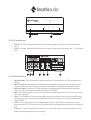
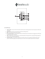
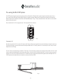
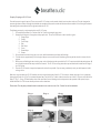
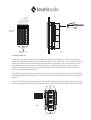
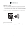
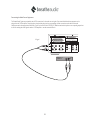
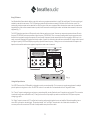
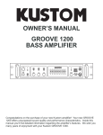
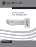
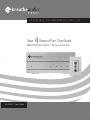
EXPERIENCE
Savor
THE
RHYTHM
OF
YOUR
4 Rooms of Pure, Clean Sound
Whole Home Music System | Two Source Four Zone
BA-2430DA | Owners Manual
LIFE
ENGLISH
IMPORTANT SAFETY INSTRUCTIONS
Danger
Exposure to extremely high noise levels may cause a permanent
hearing loss. Individuals vary considerably to noise induced hearing
loss but nearly everyone will lose some hearing if exposed to sufficiently
intense noise for a sufficient time. The U.S. Government's
Occupational Safety and Health Administration (OSHA) has specified
the following permissible noise level exposures:
1.
2.
3.
4.
5.
DURATION PER DAY (HOURS) 8 6 4 3 2 1
SOUND LEVEL (dB)
6.
7.
90 93 95 97 100 103
8.
According to OSHA, any exposure in the above permissible limits could
result in some hearing loss. Ear plugs or protectors in the ear canal or over
the ears must be worn when operating this amplification system in order to
prevent a permanent hearing loss. If exposure in excess of the limits as
put forth above, to insure against potentially harmful exposure to high
sound pressure levels, it is recommended that all persons exposed to
equipment capable of inducing high sound pressure levels, such as this
amplification system, be protected by hearing protectors while this unit is in
operation.
9.
10.
CAUTION
RISK OF ELECTRIC SHOCK
DO NOT OPEN
11 .
12.
CAUTION: TO REDUCE THE RISK OF ELECTRIC SHOCK, DO
NOT REMOVE CHASSIS. NO USER-SERVICEABLE
PARTS INSIDE. REFER SERVICING TO QUALIFIED
SERVICE PERSONNEL.
AVIS: RISQUE DE CHOC ELECTRIQUE-NE PAS OUVRIR.
13.
THIS SYMBOL IS INTENDED TO ALERT THE USER TO THE PRESENCE
OF NON-INSULATED "DANGEROUS VOLTAGE" WITHIN THE
PRODUCT'S ENCLOSURE THAT MAY BE OF SUFFICIENT MAGNITUDE
TO CONSTITUTE A RISK OF ELECTRIC SHOCK TO PERSONS.
14.
15.
THIS SYMBOL IS INTENDED TO ALERT THE USER TO THE PRESENCE
OF IMPORTANT OPERATING AND MAINTENANCE (SERVICING)
INSTRUCTIONS IN THE LITERATURE ACCOMPANYING THE UNIT.
APPARATUS SHALL NOT BE EXPOSED TO DRIPPING OR SPLASHING
AND THAT NO OBJECTS FILLED WITH LIQUIDS, SUCH AS VASES,
SHALL BE PLACED ON THE APPARATUS.
16.
1
Read all safety and operating instructions before using this
product.
All safety and operating instructions should be kept for future
reference.
Read and understand all warnings listed on the operating
instructions.
Follow all operating instructions to operate this product.
This product should not be used near water, i.e. Bathtub,
sink,swimming pool, wet basement, etc.
Only use dry cloth to clean this product.
Do not block any ventilation openings, It should not be placed flat
against a wall or placed in a built-in enclosure that will impede the
flow of cooling air.
Do not install this product near any heat sources ;such
as,radiators, heat registers, stove or other apparatus (including
heat producing amplifiers) that produce heat.
Do not defeat the safety purpose of the polarized or groundingtype plug. A polarized plug has two blades with one wider than the
0ther.A grounding-type plug has two blades and a third grounding
prong. The wide blade or the third prong are provided for your
safety If the provided plug does not fit into your outlet, consult an
electrician for replacement of the obsolete outlet.
Protect the power cord being walked on or pinched, particularly at
Plugs, convenience receptacles and the point where they exit
from the apparatus. Do not break the ground pin of the power
supply cord.
Only use attachments specified by the manufacturer.
Use only with the cart, stand, tripod, bracket, or table specified by
the manufacturer or sold with the apparatus. When a cart is used,
use caution when moving cart/apparatus combination to avoid
injury from tip-over.
Unplug this apparatus during lightning storms or when unused for
long periods of time.
Care should be taken so that objects do not fall and liquids are
not spilled into the unit through the ventilation ports or any other
openings.
Refer all servicing to qualified service personnel. Servicing is
required when the apparatus has been damaged in any way;
such as, power-supply cord or plug is damaged, liquid has been
spilled or objects have fallen into the apparatus, the apparatus
has been exposed to rain or moisture, does not operate normally
or has been dropped.
WARNING: To reduce the risk of fire or electric shock, do not
expose this apparatus to rain or moisture.
FRENCH
IMPORTANTES INSTRUCTIONS DE SECURITE
1. Lire avec attention toutes les recommandations et précautions
d'emploi avant d'utiliser ce produit.
2. Toutes les recommandations et précautions d'emploi doivent être
conservées afin de pouvoir s'y reporter si nécessaire.
3. Lire et comprendre tous les avertissements énumérés dans les
précautions d'emploi.
4. Suivre toutes les précautions d'emploi pour utiliser ce produit.
5. Ce produit ne doit pas être utilisé près d'eau, comme par exemple
baignoires, éviers, piscine, sous-sol humides ... Etc.
6. Utiliser exclusivement un chiffon sec pour nettoyer ce produit.
7. Ne bloquér aucune ouverture de ventilation. Ne pas placer le
produit tout contre un mur ou dans une enceinte fernée, cela
gênerait le flux d'air nécessaire au refroidissement.
8. Ne pas placer le produit près de toute source de chaeur telle que
radiateurs, arrivées d'air chaud, fourneaux ou autres appareils
générant de la chaleur (incluant les amplificateurs producteurs
de chaleur) .
9. Ne pas négliger la sécurité que procure un branchement polarisé
ou avec raccordement à la terre, Un branchement polarisé
comprend deux fiches dont l'une est plus large que l'autre. Un
branchement à la terre comprend deux fiches plus une troisième
reliée à la terre. Si la fiche secteur fournie ne s'insert pas dans
votre prise de courant. consulter un 'électricien afin de remplacer
votre prise obsolète.
10. Protéger le cordon d'alimentation de tout écrasement ou
pincement, particulièrement au niveau des fiches, des
réceptacles utilisés et à l'endroit de sortie de l'appareil. Ne pas
casser la fiche de terre du cordon d'alimentation.
11. Utiliser uniquement les accessoires spécifiés par le constructeur.
12. Utiliser uniquement avec le chariot de transport, le support, le
trépied, la console ou la table spécifiés par le constructeur ou
vendus avec l'appareil. Lors de l'utilisation d'un chariot, bouger
avec précaution l'ensemble chariotlappareil afin d'éviter les
dommages d'un renversement.
13 Débrancher cet appareil lors d'orages ou s'il n'est pas utilisé
pendant une longue période.
14. Des précautions doivent être prises afin qu'aucun objet ne tombe
et qu'aucun liquide ne se répande à l'intérieur de l'appareil par
les orifics de ventilation ou n'importe quelle autre ouverture.
15. Pour toutes interventions techniques s'adresser à un technicien
qualifié.L'intervention technique est nécessaire lorsque l'appareil
a été endommagé de n'importe quelle façon, comme par
exemple si le cordon secteur ou sa fiche sont détériorés,si du
liquide a coulé ou si des objets sont tombés à l'intérieur de
l'apparei1,si l'appareil a été exposé à la pluie ou à l'humidité, s'il
ne fonctionne pas normalement ou s'il est tombé.
16. ATTENTI0N:Pour réduire le risque d'incendie ou de choc
electrique ne pas exposer l'appareil à la pluie ou à l'humidité.
Danger
L‘exposition a des niveaux eleves de bruit peut provoquer une perte
permanente de l’audition, Chaque organisme humain reagit
differemment quant a la perte de l’audition, mais quasiment tout le
monde subit une diminution de I’acuite auditive lors d’une exposition
suffisamment longue au bruit intense. Les autorites competentes en
reglementation de bruit ont defini les expositions tolerees aux niveaux
de bruits:
DURE EN HEURES PAR JOUR
8 6 4 3 2 1
INIVEAU SONORE CONTINU EN dB
90 93 95 97 100 103
Selon les autorites, toute exposition dans les limites citees ci-dessus,
peuvent provoquer certaines pertes d’audition. Des bouchons ou
protections dans l’appareil auditif ou sur l’oreille doivent etre portes lors
de l’utilisation de ce systeme d’amplification afin de prevenir le risque
de perte permanente de l’audition, Dans le cas d’expositions
superieures aux limites precitees il est recommande, afin de se
premunir contre les expositions aux pressions acoustiquese I evees
potentielIement dangeure u ses, aux personnes exposees aux
equipements capables de delivrer de telles puissances, tels ce
systeme d’amplification en fonctionnement, de proteger l’appareil
auditif.
ATTENTION
RISQUE DE CHOC ELECTRIQUE
NE PAS OUVRIR.
ATTENTION: AFIN DE LlMlTER LE RISQUE DE CHO ELECTR/QUE, NE
PAS ENLEVER LE CHASSIS. NE CONTIENT PAS DE
PIECES POUVANT ETRE REPAREE PAR L’UTILISATEUR.
CONFER LE SERVICE APRES-VENTE AUX
REPARATEURS
CE SYMBOLE A POUR BUT D'AVERTIR L'UTILISATEUR DE LA PRESENCE
DE VOLTAGE DANGEREUX NON-ISOLE A L'INTERIEUR DE CE PRODUIT
QUI PEUT ETRE DE PUISSANCE SUFFISAMMENT IMPORTANTE POUR
PROVOQUER UN CHOC ELECTRIQUE AUX PERSONNES.
CE SYMBOLE A POUR BUT D'AVERTIR L'UTILISATEUR DE LA PRESENCE
D'INSTRUCTIONS D'UTILISATION ET DE MAINTENANCE DANS LES
DOCUMENTS FOURNIS AVEC CE PRODUIT.
AFIN DE REDUIRE LES RISQUÉ D'INCENDIE ET DE DECHARGE
ELECTRIQUE, NE PAS EXPOSER CET APPAREIL A LA PLUIE OU A
L'HUMIDITE.
2
BreatheAudio™ - Elevate™
Two-Source, Four Zone Whole Home Music System
BA-2430
Congratulations on your decision to purchase BreatheAudio's new Elevate whole home music system. We hope that you will have hours and hours of
enjoyment, while your home comes alive with the celebration of sound. This Elevate system is the first in our line of good, better and best systems and
offers advanced technology and superior sound, but with the simplicity of user-friendly design and at a very attainable price.
Elevate provides clean, rich sound in a multi-source, multi-room application, that includes features more typically found in much more expensive units.
With Elevate you can access two sound sources from elsewhere in your house, and play audio through speakers in up to four zones (or rooms). Elevate
also has a built-in infrared repeater, which means that a remote control provided with either of the system's music devices can be remotely operated
from any of the rooms that you have wired for sound by aiming the remote at the keypad. The IR receiver picks up the signal and sends it back to the
selected source unit, responding to your every command.
For it's easy-to-use design, Elevate provides some rather advanced features. Each listening zone can be turned on or off independently, with a quick
press of the Power button. By holding the button for a second or more, all zones can be powered down from any keypad. A Mute function is available
which allows a momentary silencing of the zone. The system also comes with a convenient handheld IR remote control which, when pointed at the
zone keypad, duplicates ALL keypad zone-control functionality.
We hope that you will enjoy this new adventure in music in your home, and wish to hear any and all comments that you have about the features and
overall performance of our product. As you set up and use your new Elevate™ system, please contact us and let us know what you think at:
Customer Service
Toll Free #: 866-889-1019
Email: [email protected]
3
WHOLE HOME MUSIC SYSTEM TWO SOURCE FOUR ZONE
STAND BY
ZONE 1
ZONE 2
1
ZONE 3
ZONE 4
2
BA-2430 Front Panel Features
1
2
Stand-by: This LED (light-emitting diode) indicates that the 2430 System is plugged into an AC power source and the Power button is
pushed.
Zone LEDs: These light-emitting diodes indicate that a zone control keypad is turned on. When lit, that particular zone, 1-4, is turned on and
active.
AllPort
SPEAKER AND DATA SIGNALS
MODEL BA-2430
Two Source Four Zone
Whole Home Music System
FUSE:T2AL 250V
120V
60Hz 150W
www.breatheaudio.com Cincinnati Ohio USA
IR OUT
OUTPUT
SOURCE INPUT
IN T
ERTEK
CM
IN
OUT
L
L
R
R
SOURCE 1
SOURCE 2
56KHz
38KHz
OUT
IN
1
CONTROL
US
C
3033118
WARNING: TO REDUCE THE RISK OF
FIRE OR ELECTRIC SHOCK. DO NOT
1
2
3
2
AUDIO
NORMAL
USE
4
5
USE FOR SAT
OR CABLE
6
THIS DEVICE COMPLIES WITH PART 15 OF THE FCC RULES.
OPERATION IS SUBJECTED TO FOLLOWING TWO CONDITIONS:
(1) THIS DEVICE MAY NOT CAUSE HARMFUL INTERFERENCE,AND
(2) THIS DEVICE MUST ACCEPT ANY INTERFERENCE RECEIVED,
INCLUDING INTERFERENCE THAT MAY CAUSE UNDESIRED OPERATION.
7
BA-2430 Back Panel Features
1
2
3
4
5
6
7
Audio Source Inputs: The 2430 is designed to accept up to two audio sources. These are attached to the 2430 using a standard stereo
RCA cable.
Allport™ Connection: An important feature of the BreatheAudio System is the single connection point for all of the speakers and Cat-5
control cables for each zone. This multi-pin connection is where the included Allport™ cable plugs into the main amplifier component.
Audio Source Outputs: A feature of the 2430 is the ability to take an audio signal plugged into the audio inputs and send that signal to
another device. That is done through the audio outputs using standard stereo RCA cables.
Audio: The audio signal selected for zone 4 can be easily sent to an external amplifier using this output. The volume level is then controlled
from the zone control keypad.
Control: The 2430 allows the use of an external power amplifier for areas of the home that are larger and require more amplifier output.
This voltage trigger is used for turning on the external amplifier when the zone control keypad is turned on. This insures that the amplifier is
not left on indefinitely.
IR OUT: Each control keypad in every zone of the installation contains an IR receiver. This enables control of the audio sources using a
wireless remote control. The 2430 has two choices for the operating frequency of the IR signal being sent to the audio source equipment, see
pg. 11.
AC Power: The 2430 must be plugged into an active AC power source. A detachable power cord is provided for this purpose. The main
amplifier component is designed to be left on once it is turned on.
4
VOLUME
MUTE
1
A
2
3
4
B
PWR
5
6
BA-2430KP Keypad
1
2
3
4
5
6
Volume Indicator: This series of seven LEDs provide a visual reference for the listening volume level. Each LED represents a 4 dB increase
in the volume.
Volume Buttons: These buttons raise and lower the audio volume in that keypad's zone.
MUTE: The mute button temporarily silences the audio.
Source Selection Buttons: The buttons labeled A and B are for individual selection of the two audio sources plugged into the 2430 System.
The selected source button will remain lit.
PWR: This ON/OFF button turns that keypad's zone on and off independently. If the keypad is turned on, pushing and holding this button will
turn all the zones of the system off simultaneously.
IR Receiver Window: The 2430 System is designed to receive wireless remote control commands from both keypad controls of the
system, or from the audio equipment connected to the system. The receiver for these commands is located under the red IR window.
5
Pre-wiring the BA-2430 System
The 2430 System is designed to operate using two types of wire. Standard Cat-5 Network cable is used for keypad control of the system. Two- or
four-conductor audio cable sends the audio signal to each pair of speakers in the four listening zones. Both types of wire should be concealed in the
walls of the home and are installed on the back side of the BreatheAudio Allport™ (fig. 1). Proper termination of each of the cables is crucial to reliable
operation of the entire system.
Be sure to label each Cat-5 for its appropriate zone. This is important for future reference.
Left
Zone 4
- +
+
-
Lef t
Ri ght
Right
Zone 1
- +
-
+
Left
Right
-
+
+
Righ t
Zon e 2
- +
Zon e 3 Left
+ -
Fig. 1
Terminating Cat-5
Be careful not to place the Cat-5 runs next to AC power cables. Doing so will cause noise and interference in the data being sent to and from each zone.
To avoid this interference it is best to leave at least one stud space between the Cat-5 and AC power lines. If it is necessary to cross AC wires, it should
always be done at a 90 angle.
The Cat-5 cables are terminated using a modular RJ-45 jack (fig. 2). This is the same type of jack used on computer Ethernet cables. Each Cat-5 cable
has four colored wires twisted together in pairs inside an outer jacket. Each pair consists of a solid and striped wire. The colors are green, orange, blue,
and brown. The order of the colored wires inside the RJ-45 determines proper communication between the keypads and the main amplifier unit. The
2430 System uses the standard Ethernet or network color scheme referred to as 568A.
Fig. 2
6
Properly Crimping an RJ-45 Jack
First and foremost is a good crimp tool. There are several RJ-45 crimpers on the market, but the best is a ratchet-style tool. The tool is designed to
squeeze eight brass conductors through the individual wire insulation so they make contact with the internal brass strands. Each of the eight conductors
must make good contact with each of the eight wires inside the RJ-45.
The following are step-by-step instructions for each RJ-45 crimp:
1 Slice and peel back about 2 to 3 inches of the Cat-5 jacket, exposing the inner wires.
2 Untwist each of the pairs. Arrange them in the proper order. The correct 568A color order from left to right is:
1. Orange Stripe
2. Orange
3. Green Stripe
4. Blue
5. Blue Stripe
6. Green
7. Brown Stripe
8. Brown
3 Once you have the wires in the proper color order, hold them between your thumb and forefinger.
4 Trim the wires to approximately ½ inch in length so they are even across the end. Note that a good crimp tool has a built-in trimmer for this
purpose.
5 While you are still holding the wires in their proper order, slide them into the open end of the RJ-45 connector with the tab pointing down. Be
sure to push the wires all the way to end of the connector. The RJ-45 has a crimp point at the open end that should extend over the edge of
the Cat-5 jacket.
6 Place the RJ-45 into the crimp tool and squeeze the tool as far as possible. If you are using a ratchet style tool, you should squeeze it until it
no longer clicks.
When the crimp is complete, the RJ-45 should be securely crimped to the jacket of the Cat-5. This insures a reliable connection. It is very important
that each end of each run of Cat-5 is terminated the same way. Each of the Cat-5 cables is then inserted into one of the RJ-45 ports on the back of the
Allport™ (fig. 3 - See pg. 8). Note that the order of the connections for each listening zone is not important to the operation of the system, but you
should label each Cat-5 for its zone should you have to refer to them later.
Please note: The only way to know that the termination is accurate is to use a Cat-5 tester for each termination.
Step 1
Step 2
Step 3
Step 4
Step 5
Step 6
7
Gro
und
IR
Sig
Gro nal Sou
u
rce
Con nd
1
tr
Con ol Da
tro ta B
lD
u
IR
Sig ata sGro nal - Bus+
Sou
u
rce
+12 nd
VP
2
ow
er
Top view with
tab down.
1 2 3 4 5 6 7 8
Pair 2
Pair 1
Pair 3
Pair 4
Fig. 3
Wires insert from
this end.
Terminating Speaker Wire
There are two types of speaker wire that can be used for distributing the audio signal to each listening zone. Each stereo output consists of a
separate left and right positive and negative lead. To accommodate these, use two- or four-conductor wire. The two-conductor wire has a red
and black strand inside the outer jacket. Red is used for the positive signal and black for the negative. The four-conductor wire has red, black,
green, and white. In this case, the white is positive and the green is negative. Each BreatheAudio speaker output is aligned so the first two
terminals are left negative and positive and the second two are right negative and positive. These terminations are located on the back of the
Allport™ connection hub included with the system.
The insulation on each lead from the speaker wire needs to be stripped back about ½ inch exposing the brass wire. Each wire is then inserted into
the appropriately labeled connection on the Allport™ and is secured by turning the screw above each wire clockwise until it is snug against the
wire (fig. 4).
+
Right
Right
Z one 3
+ Lef t
Zon e 1
+ -
-
Le ft
Ri ght
Zone 4
+ -
Right
-
Zo ne 2
+ +
Left
L eft
-
8
+
-
Fig. 4
+
Each zone in the 2430 System is designed to handle a pair of 8-ohm speakers. Multiple pairs of speakers or speakers that present less than an 8ohm load to the amplifier will cause the amplifier to overheat and shut down. This could cause permanent damage to the amplifier's output stage.
Installing the Allport™ Multi-connection Hub
The Allport™ is a unique connection that enables the speaker and keypad connections to be made with one cable. Once the Cat-5 cables and
speaker wires are connected to the back of the Allport™, it can then be installed into a single-gang, low-voltage ring. These are available either
as a ring designed to attach to a wall stud prior to the drywall installation, or installed after the drywall is finished using the type that has wings or
“dog-ears” that screw down to the drywall. The Allport™ connection cable is 10 feet long, so the location of the Allport™ needs to be within 10
feet of the equipment.
Once the Allport™ is installed in the wall, the Allport™ cable can be installed and tightened down and the other end installed at the back of the
2430 amplifier and tightened down (fig. 5).
Fig. 5
AllPort
SPEAKER AND DATA SIGNALS
SOURCE INPUT
IN
OUT
L
OUT
IN
L
R
R
SOURCE 1
SOURCE 2
Proper Placement of the BA-2430 Main Amplifier
The main amplifier unit is designed to be located centrally with the audio source equipment and the Allport™ connection hub. Care should be taken
to provide ample ventilation to adequately dissipate heat. It is best to leave 1 ½ to 2 inches of ventilation space around the amplifier.
9
Connecting the Audio Source Equipment
The BreatheAudio Systems use standard stereo RCA connections for the audio source signals. Up to two individual audio components can be
plugged into the 2430 amplifier. Simply plug the red and white plugs into the corresponding colored connections on the back of the audio
components and to the appropriate connections 1 and 2 on the back of the 2430 (fig. 6). Note that each audio input has a corresponding output that
is used for sending the audio signal to another 2430 amplifier or an alternate audio source.
AllPort
SPEAKER AND DATA SIGNALS
Fig. 6
MODEL BA-2430
Two Source Four Zone
Whole Home Music System
FUSE:T2AL 250V
120V
60Hz 150W
www.breatheaudio.com Cincinnati Ohio USA
OUT
L
L
R
R
SOURCE 1
SOURCE 2
56KHz
38KHz
OUT
IN
Source 1
Tuner 1
10
IR OUT
OUTPUT
SOURCE INPUT
IN
1
CONTROL
2
AUDIO
NORMAL
USE
Audio
Out
USE FOR SAT
OR CABLE
Using IR Emitters
Each BreatheAudio System has the ability to control the audio source equipment attached to it, using IR (infrared) signals. This is the control signal
emitted by a wireless remote control. The 2430 package contains IR mouse emitters necessary for this kind of source function control. The
emitters plug into these outputs and are attached over the IR receiver of the source equipment. When the wireless remote control is aimed at the
keypad and one of the remote command buttons is pushed, that IR command is sent through the emitter and initiates that command for the source
equipment (fig. 7).
The 2430 System has two choices of IR outputs for each of the two audio source inputs. Some source components operate at a lower IR carrier
frequency (38,000 kHz), and some operate at a higher frequency (56,000 kHz). There is no way of knowing which output is appropriate, other
than the source equipment may be nonresponsive, or have sporadic responses to issued commands for the source equipment. If this occurs, it is
easily corrected by plugging the IR emitter into the other output. A general rule of thumb is that cable boxes and satellite TV receivers often respond
to a higher frequency, and CD and DVD players typically respond to a lower frequency. Making the correct choice about which IR output to use
depends on how well the audio source equipment responds to remote control commands.
AllPort
SPEAKER AND DATA SIGNALS
MODEL BA-2430
Two Source Four Zone
Whole Home Music System
FUSE:T2AL 250V
120V
60Hz 150W
www.breatheaudio.com Cincinnati Ohio USA
OUTPUT
SOURCE INPUT
IN
OUT
L
OUT
IN
R
SOURCE 1
SOURCE 2
56KHz
1
CONTROL
L
R
IR OUT
38KHz
2
AUDIO
NORMAL
USE
USE FOR SAT
OR CABLE
Fig. 7
Using the Output Section
The OUTPUT section of the 2430 amplifier is designed to control an external amplifier. This is necessary to provide enough power for multiple
pairs of speakers in a single area or zone. The OUTPUT section is for use with zone 1 and works with the zone 1 keypad for volume.
The “Control” output is a voltage trigger used to turn an external amplifier on and off when the zone 1 keypad is turned on and off. This connection
is made with a single mono cable with a mini (3.5 mm) jack on each end. Any amplifier you wish to control with the 2430 System requires a
voltage trigger input.
The “Audio” output is a stereo mini (3.5 mm) jack and is used to provide an audio signal to the external amplifier. Most audio amplifiers have a
stereo RCA-type input for the audio signal. This input has labeled “Left” and “Right” channels and is color coded with red and white. The
necessary stereo mini connection to RCA cable is readily available at any electronics retailer.
11
Using the BA-200 Audio Amplifier
The BreatheAudio BA-200 stereo amplifier is designed to easily integrate with the 2430 System. The BA-200 is the same size chassis and will sit
side-by-side with the 2430 on a standard double-space rack shelf.
The BA-200 includes the necessary voltage trigger cable and stereo mini to transfer the audio signal. Once the two connections are made, the BA200 amplifier increases and decreases in volume, and turns on and off with the zone 1 keypad.
Changing the Zone Address for the BreatheAudio Keypads
The 2430 System keypads are pre-addressed for each of the four zones. The label on the back of the keypad denotes the correct zone number for
each keypad location (fig. 8).
Changing the zone setting for the keypads is easily done. To do this, remove the insert cover plate from the keypad. On the upper right hand side of
the PC board are four pairs of wire jumpers. These are labeled ZN1, ZN2, ZN3, and ZN4. Simply move the plastic shunt from its current location
to the appropriate zone number (fig. 9).
It is important to note that no two or more keypads in an installation can have the same zone setting. This will prevent the keypads from
communicating.
VOLUME
ROOM KEYPAD CONTROLLER
BA-2430KPZ1
WARNING: Use only with the Breatheaudio
Elevate Audio System
AVIS: Utiliser uniquement avec Breathaudio
Elevate System
Breatheaudio LLC, Cincinnati, Ohio, USA
Using a pair of needlenose pliers, lift the zones
shunt off of the two
prongs and transfer it to
the appropriate zone.
MUTE
A
ZONE 1
B
PWR
Fig. 8
Fig. 9
12
Teaching a Universal Remote Control Using the BA-2430RC Remote Control
The 2430 System includes a wireless remote control that will perform the same functions as the keypads. This is a useful tool for teaching the Breathe
Audio keypad functions to a universal learning remote, which is a remote control that has the ability to learn the IR function codes for multiple pieces of
audio source equipment. This allows control from one remote control, as opposed to several remotes from different manufacturers.
The process for teaching IR codes to a learning remote varies with each different manufacturer. Read the instructions for putting your learning remote in
learn mode. Teaching is done by aiming the BreatheAudio remote at the learning remote and pressing the desired function button. The learning remote
will indicate that it has received the code, and it will then store that code for future use.
Troubleshooting
Symptom
Probable Cause
Remedy
The system goes completely dead and
eventually turns back on.
The load on the amplifier is too great and it is
going into thermal protection.
Make sure that you are not using more than one pair
of speakers on each zone. Check the speaker rating
and make sure it is not less than 8-ohms per
speaker. Use an external amplifier to accommodate
a heavier load, see page 11, Using the Output
Section. Make sure that the main amplifier has
sufficient ventilation.
The keypad's power button flashes and
there is no functionality.
Two keypads in use have the same zone
setting, or the Cat-5 cable is not properly
terminated.
Check the zone label on the back of the keypads,
and check the keypad zone setting under the insert
cover plate, see page 12, Changing the Zone
Address for the BreatheAudio Keypads. Using a
Cat-5 tester, verify the RJ-45 termination on each
end of the Cat-5.
IR control of audio source equipment is
sporadic or does not function at all.
The IR emitter is not plugged into the correct IR
output on the back of the 2430 amplifier. The
IR emitter flasher is not located directly over
the IR receiver on the audio source equipment.
The IR emitter is not completely plugged into
the amplifier output.
Change the emitter from the 38K output to the 56K
output or vise versa. Have someone aim the source
remote control at the keypad and push a function
button. If the emitter is functioning properly, it will
flash. Move the emitter around the face of the audio
source equipment until it functions reliably. That is
the proper location for the emitter. Press on the
emitter jack at the back of the 2430 to make sure
the emitter is fully plugged in.
13
Troubleshooting
Symptom
Probable Cause
Remedy
The BreatheAudio remote control does
not change the functionality of the
keypad.
The batteries are bad or improperly installed.
Replace or reorient the batteries in the remote
control.
The output from the speakers is not as
good as it should be.
The positive and negative leads for the
speakers are not properly installed. The
speaker wires may not be making good contact
at the Allport™ hub.
Check each speaker wire connection at the
Allport™ hub. The proper orientation should be Left
-, + and Right -,+. Make sure that each termination
is tight and making good contact with bare wire.
Specifications
Power Amplifier Section
Continuous Average Output Power
Two channels driven, 30-20kHz
Rated Distortion (1/2 power)
Rated Impedance
Damping Factor
Frequency Response (30-20kHz)
15W
@ 1% THD
0.40%
8 Ohms
50+
+/-3dB
Preamplifier Section
Input Impedance
Input Sensitivity for rated power
Input Overload
50k
330mV RMS
3V RMS
IR System
Source Outputs
Output Drive Current
Output Drive Voltage
Compatible with single and dual emitters
NuVo reserves the right to change specifications without notice.
Power Requirements
Power Supply
Power Consumption all
channels driven to full-rated power
Power Consumption average
operating conditions
Power Consumption no signal
USA Safety Listing
Physical Specifications
Unit Size Millimeters
Unit Size Inches
Shipping Size Millimeters
Shipping Size Inches
Unit Weight Kilograms
Unit Weight Pounds
Shipping Weight Kilograms
Shipping Weight Pounds
2
100mA
12V
14
120VAC/240VAC 50/60Hz
190VA (166W)
88VA (70W) 1/8 power
14VA (10W)
ANSI/UL-6500
89 x 216 x 325
3.5 x 8.5 x 12.75
190 x 305 x 394
7.5 x 12 x 15.5
3.5
7.8
5
11.8
4940 Delhi Pike
Cincinnati, OH 45238 USA
513.347.2180
www.breatheaudio.com