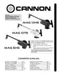
1
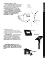
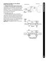
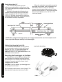
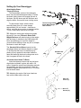
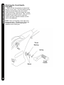
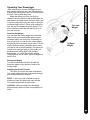
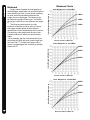
CAUTION:
READ THIS MANUAL CAREFULLY
BEFORE OPERATING YOUR NEW
CANNON® DOWNRIGGER.
RETAIN FOR FUTURE REFERENCE.
Uni-troll 10ts
Uni-troll 10
NOTE: Do not return your CANNON® Downrigger to your
retailer. Your retailer is not authorized to repair or replace this
unit. You may obtain service by:
• calling CANNON® at 1-800-227-6433;
•
•
returning your downrigger to the Factory Service Center;
sending or taking your downrigger to any CANNON®
Authorized Service Center on enclosed list.
Please include proof of purchase, serial number and purchase
date for warranty service with any of the above options.
Uni-troll 5
OWNER’S MANUAL
Introduction to Downriggers
Mounting Your Downrigger
Attaching the Crank Handle
Terminator & Line Release
Cannon Uni-Release
Attaching the Rod Holder
Operating Your Downrigger
pg. 2
pg. 2-7
pg. 8
pg. 9
pg. 9
pg. 10
pg. 11
The Effects of Blowback
Maintaining Your Downrigger
Troubleshooting
Trolling Tips
Warranty Information
Cannon Service Policy
Authorized Service Centers
pg. 12
pg. 13
pg. 13
pg. 14
pg. 15
pg. 15
See List
Introduction to downriggers
Introduction to Controlled Depth Fishing
Undoubtedly there are many fishermen
familiar with the methods and use of controlled
depth fishing. During the mid 1960's the state of
Michigan introduced Pacific salmon into the Great
lakes in an attempt to revitalize its sport fishing
industry. From this successful transplant, new
fishing techniques and equipment were
developed. One such method was controlled
depth fishing which enabled fishermen to place a
lure at a desired depth by utilizing downriggers.
Because of the varying factors (water
temperature, thermocline, weather, tides, time of
day, or time of year) it is necessary for successful
fishing to maintain specific water depths that
coincide with fish movements and feeding
patterns.
One essential feature of the downrigger is
the depth meter or gauge that indicates lure
depth. This allows the angler to control as well
as return to specific depths where fish have
been caught.
Due to the success of controlled depth
fishing, downriggers are now being used
throughout the world to catch a wide variety of
species in both fresh and salt water. Whether
fishing for blues off Rhode Island, walleyes in
Lake Erie, sailfish off the coast of Florida, or
stripers in Tennessee, the use of downriggers
will make your fishing more successful and more
enjoyable.
Attach Line Release
to Rear Hook on
Weight
Parts Description
1. Reel
This is used to spool the cable, available in lengths ranging from 150 to 400 feet.
2. Boom
This is used to extend the weight out from the body of the downrigger and has a pulley fixed
to its end. Boom lengths range from 24 to 53 inches.
3. Swivel Head
This relays the cable at the end of the boom to lower the weight.
4. Weight
This is used to maintain the depth at which you want to fish. Sizes of weights range from 4 to
20 lbs.
5. Cable
This connects to the weight. Cable material is 150 lb. test stainless steel cable.
6. Depth Meter
This determines how much cable you have run out, enabling you to choose your trolling
depth.
7. Mounting Base This attaches to the boat, enabling you to place the downrigger where you choose.
8. Rod Holder
2
This holds your fishing rods while trolling and may also be used for storing rods.
Mounting Accessories
Deck Plates are necessary when extra
strength must be added to the base material of
the boat and for attaching the downrigger to other
mounting accessories.
Gimbal Mounts are designed to fit mediumsized flush mounted rod holders built into the
gunwale of many larger fishing boats and
cruisers. Only sturdy, high quality rod holders
should be used for this temporary mounting
system. Gimbal mounts are available in 9” or 12”
post lengths.
MOUNTING & SETUP
Downrigger Mounting on Boats
A downrigger should be mounted where ever it
is easy to operate and observe. You want to be
able to see your fishing rod and to react quickly.
So, choosing a good spot to mount your
downrigger on your boat is 99% of the job.
Due to the great variety of boats available,
mounting your downrigger can be a dilemma.
Having proper mounting accessories is essential.
Cannon has a complete line of mounting
accessories to conveniently mount your
downriggers on any boat.
Arrows
Indicate
Mounting
Locations
Deck Plate
Gimbal Mount
Clamp Mounts can be mounted at the
junction of two rail sections with the aid of two ¼"
pieces of plywood. They will protect your rail from
any marks from the clamp and provide a non-slip
surface.
Clamp Mount
3
MOUNTING & SETUP
Side Rail Mounting
Side/Rail mounts can be mounted to a
welded T-section. It can also be used at the two
rail section butt joint. In both installations it is
recommended to use a non-slip material, such
as rubber or a thin wood sheet, between metal
surfaces.
You can also use these for mounting to a very
narrow side gunwale. There is a plate provided
for back-up with bolts and washers. If the
gunwale compartment is foamed in, then
wellnuts should be used. It is also recommended
to install two additional flat head screws through
the top plate for stabilization (you will need to
drill and countersink).
Side/Rail on T-Section
Side/Rail on Gunwale
NOTE: In no case should this mount be used
on fiberglass ¼" thick or less unless it is
foamed in.
Pedestal Mounting
Pedestals are used wherever additional height is
needed for ease of operation or to clear
obstructions, such as handrails.
Caution: When using a pedestal mount or side/
rail mount, do not extend the
telescopic boom on your Uni-Troll.
The increased leverage will cause
excessive strain and possible failure
of the mount.
4
Pedestal for Additional Height
Decks up to 7/16" thick
Where access to the underside of the deck is
not available, the mounting base can be mounted
using wellnuts. Use the base as a template to mark
locations and drill four 1/2" holes. Mount the base
using four 1/4"-20 x 1 1/2" truss head screws and
four wellnuts. Tighten the screws so the wellnuts are
firmly compressed as pictured.
Decks thicker than 7/16"
For decks thicker than 7/16", or where the
underside of the deck is accessible, mount the base
with screws, nuts, and washers. Use the base as a
template to mark the locations and drill four 9/32"
holes. Use four 1/4" -20 x 2 1/2" truss head screws
and four each flat washers, lock washers, and nuts.
Fasten the base to the deck as pictured.
NOTE: Wellnuts cannot be used on decks thicker
than 7/16".
Stern Facing
Outboard Facing
Rear
or
Stern
Side
or
Gunwale
Decks
up to
7/16"
Thick
Note Locking
Slots in Base
MOUNTING & SETUP
Installing the Base on Your Boat
Base
Wellnuts
Base
Decks Thicker Than 7/16"
Washer, Lock Washer,
and 1/4-20 Hex Nut
5
MOUNTING & SETUP
Decks thinner than 1/4"
Use a Cannon Deck Plate to prevent
deflection and add stability to decks thinner than
1/4". Use the deck plate as a template to mark the
hole locations.
If access to the underside of the deck is not
available, the deck plate can be mounted using
screws and wellnuts. Drill 1/2" holes. Use four
1/4”-20 x 2" flat head screws and four wellnuts to
mount deck plate as pictured. Tighten the screws
so the wellnuts are firmly compressed.
Where the underside is accessible, mount the
deck plate using screws, nuts, and washers. Drill
9/32" holes. Use four 1/4”-20 x 2" flat head
screws, nuts and washers (flat and lock). Fasten
plate to deck as pictured. To secure the low-profile
base to the deckplate use four 1/4”-20 x 1 1/2"
truss head screws.
Cannon Deck Plate
Deck Up to 7/16" Thick
Base
Deck Thicker Than 7/16"
Wellnut
Washers, Screws,
& Nuts
NOTE: When using the telescopic boom, we strongly recommend the use of a deck plate on all
boats to provide adequate stability for the downrigger.
FOR Uni-Troll 10 and Uni-Troll 10 TS:
The Low-Profile Swivel Base mounting follows
the same procedure as for the deck plate except
that four 1/4"-20 x 1 1/2" truss head screws are
used to fasten the mounting base and four
additional 1/4"-20 x 2 1/2" truss head screws fix the
swivel base to the boat deck.
Low-Profile Swivel Base
Mounting the Downrigger on the Base
Slide the bottom of the frame over the lip of the
base, with the boom outboard or facing the stern.
Move the frame over the base until the latch clicks
into place. If properly seated, the frame should
completely cover the base.
CAUTION: If not fully seated, your downrigger can
be dislodged from the base.
Tip: Periodically check base to ensure integrity. The
base should be replaced at least every 5 years.
6
Latch
MOUNTING & SETUP
Setting Up Your Downrigger
Attaching the Boom
Telescopic Boom
The intermediate section of the telescopic
boom must be extended approximately 5" before
the boom locking screw can engage the hole in
the boom. Slip the boom end into the frame and
align the holes. Secure with boom locking screw.
To adjust boom length, with the boom
extending away from you, rotate clamps
approximately 1/4 turn counter - clockwise to
unlock, and slide boom section to desired position.
To lock, rotate clamp clock-wise until tight.
The 3/4"-Long Phillips
Screw Must Engage
Hole in Boom
TIP: Whenever downriggers with boom lengths
beyond 24" are used, Cannon's Retro-Ease
Weight Retriever will make bringing in the weight
safe and easy. It attaches to the cable below the
boom end allowing you to pull the weight to
yourself without having to lean way out or collapse
the boom to reach the weight.
Clamps
The Standard 24 Inch Boom inserts into the
downrigger frame (see bottom diagram on page
7). Be sure that the boom is held securely by
seating it firmly against the shoulder inside the
fame and fastening the boom locking screw such
that it engages the hole in the boom.
Standard 24"
Boom
Assemble Swivel Head To Boom
Insert the telescopic boom-end into the boomalign holes and fasten in place with a #8 x 5/8
screw. Spread the swivel head side plates and slip
the assembly over the boom end axle. Snap the
assembly together and install two #4 x 1/2" screws
into the swivel head.
TIP: Adjusting the angle of the boom head can
help control cable wrap on the reel.
#8 x 5/8"
Screw (1)
#4 x 1/2"
Screws (2)
7
Attaching the crank handle
Attaching the Crank Handle
Assembly
Make sure the thrust bearing is sandwiched
between its two races. The thrust bearing spring
should be oriented where the narrow end is
toward the bearing. Slide the bearing with races
and spring over the ratchet shaft. Then, carefully
thread the crank handle onto the shaft and
continue turning the handle clockwise until the
clutch is fully tightened
NOTE: Place your fingertip on the edge of the
bearing and races. This allows the crank to be
threaded more easily until the spring puts
resistance on the clutch pad.
Thrust
Bearing
Spring
Races
8
Crank
Handle
Rubber Cushion
Cable
Examine the top of the terminator and note the
order shown in the detail to run cable.
Unwind about 2 feet of cable
and thread the cable through
the rubber cushion.
CABLE IN
CABLE IN
CABLE
OUT
Attach to terminator.
Snap &
Swivel
TERMINATOR & LINE RELEASE
Terminating the Downrigger Cable
Tip: A set of pliers with wire cutters is
recommended for this part of setup.
TIP: Use only straight cable, not kinked.
Lead cable into
HOLE A.
Pull six inches of
cable through.
Thread cable
through swivel,
then up into
bottom of the
terminator.
HOLE A
Lead cable out of
HOLE B and into
HOLE C. Push
the cable until its
end touches the
inside of the
terminator hook.
Slide the cushion over the top of the
terminator and give it a test pull.
Tighten cable
by squeezing
terminator until
it snaps shut.
Then pull at top
and bottom
until drawn
tight. Make
sure that the
cable threads
in groove of
the hook.
The cable is set to attach a Cannon
Trolling Weight.
Swivel
Cannon Uni-Release
Close
The Cannon Uni-Release attaches directly to
the downrigger weight. Attach fishing line to the
clip at the end of the release, and then click
through a series of increasing tension settings.
The release can be used with any test line on salt
or fresh water and may be adjusted from 2 to 22
pounds of grip tension on the line.
To change line release tension, turn tension knob
to (+) to increase or (-) to decrease. Tension also
may vary according to where the line is placed in
the grips. Higher tension is on the line if it is set
back toward the hinge, and lower if set closer to
the opening. To open the release, spread the
release arms with thumb and forefinger applying
pressure to the sides.
Open
Tension
Adjust
Fishing Line
Open
Gripper
Pads
9
ATTACHING THE ROD HOLDER
Attaching the Rod Holder
The positive lock rod holder incorporates a
locking disk that allows the rod holder to be
aligned in 15 degree increments. Slide the rod
holder tube into the clamp to the desired position
within the recommended area (see below).
Be sure the angled shoulders are facing up.
Place the locking disk into the mating recess of
the frame.
Slip the clamp arms in place where the
obround tab on the disk fits into the slot on the
clamp. Slide the star washer between the arm of
the clamp and the frame. Place the flat washer
onto the bolt. Then insert the bolt with washer
through the clamp by entering the disk, going
through the frame, the star washer, and out the
other side of the clamp. Tighten the nut to secure
the rod holder. Reposition the rod holder by
loosening the nut and adjusting the tilt.
Single Rod Holder Assembly
Recommended
Area to Clamp
Rod Holder
Angled
Shoulder
10
Star Washer
Placement
CAUTION: This rod holder is intended for use
of up to 30 lb. test line only, and is not
recommended for use with any tackle IGFA
rated higher than 30 lb. A safety strap (not
included) is recommended for all
applications.
The rod holder assembly is not warranted
when used with tackle above 30 lbs.
Equipment placed in the rod holders and the
loss thereof is the responsibility of the user
and is in no way warranted by JOHNSON
OUTDOORS, INC. Mounting must be in
accordance with the above instructions and
diagram to be warranted.
Dual Rod Holder Assembly
After mounting the Cannon downrigger to your
boat, release some line from your rod and reel so
that the lure is anywhere from 5 to 100 feet behind
the boat. This is called drop back.
Attach the fishing line firmly into the line
release. Lower the weight to the desired depth as
indicated on the depth meter. Place the fishing rod
in the rod holder and reel up the slack so that your
rod has a slight bend in it. When a fish strikes the
lure, the line will separate from the release. Then
you will be free to fight the fish and bring it in on
your rod and reel.
Lowering the Weight
You can lower the trolling weight at a controlled
rate by turning the crank handle gently counterclockwise (away from the boom). Depending on
how far you turn, you can let your trolling weight
descend as fast or as slowly as you wish. Turn the
crank handle clockwise (toward the boom) until it
you hear a click to stop the weight. This gives you
control to let it plunge rapidly or sink slowly to a
predetermined trolling depth. With multiple
downriggers, you could start all your weights
creeping down, one at a time, and then stop them
each in turn.
To Lower
Weight
OPERATING YOUR DOWNRIGGER
Operating Your Downrigger
To Raise
Weight
Raising the Weight
Turn the crank handle clockwise (toward the
boom) as rapidly as you desire to retrieve the
trolling weight.
Adjusting the Clutch Tension
The clutch is built into the crank mechanism.
Turn crank handle clockwise to increase the drag
and counterclockwise to reduce it.
NOTE: In case your reel continues to slip no
matter how hard you tighten the crank see the
Troubleshooting section of this booklet.
CAUTION: Remove weight from downrigger
before traveling either by water or transporting on
trailer.
11
Simply stated, blowback is what happens to
the downrigger weight when you pull it through the
water behind your boat. As your speed increases,
so does the horizontal distance between the
weight and your downrigger. The faster you go,
the farther the weight is behind you. The farther
the weight is behind you, the shallower the weight
is.
The following charts provide you with
blowback information for three sizes of Cannon
downrigger weights pulled at three different
speeds with no lures attached and with no current.
Current drag, water salinity and the use of nonCannon products will affect your actual trolling
depth.
As an example, the first chart shows that if you
are trolling at 4 MPH with an 8 pound weight and
you have 100 FT. of cable in the water with no
current; the downrigger ball is actually at a depth
of about 80 FT.
8-Lb. Weight at 2, 4, and 6 MPH
2 MPH
Actual Depth of Weight (ft.)
Blowback
Blowback Charts
Blowback
4 MPH
6 MPH
Amount of Cable in Water (ft.)
10-Lb. Weight at 2, 4, and 6 MPH
2 MPH
ActualDepth of Weight (ft.)
4 MPH
6 MPH
Amount of Cable in Water (ft.)
12-Lb. Weight at 2, 4, and 6 MPH
2 MPH
Actual Depth of Weight (ft.)
12
4 MPH
6 MPH
Amount of Cable in Water (ft.)
Maintaining Your Downrigger
At the beginning of each fishing season and
more often during periods of heavy usage, lightly
grease the thrust bearing, reel shaft bearings,
swivel head pulley, ratchet brake face, and
ratchet dog. When using for saltwater fishing,
thoroughly rinse the entire downrigger with fresh
water after each trip and lubricate on a frequent
basis. Replace the cable at least every two years.
maintaining & TROUBLE SHOOTING
Adjusting the Depth Meter
The Cannon Depth Meter provides non-slip
accuracy, plus easy resetting. To reset, just slide
the meter away from the reel until the gears are
disengaged. Spin meter gear to change setting.
NOTE: Actual fishing depth may vary from
depth shown on meter due to trolling speed
and weight of cannon ball. (See "Blowback")
For repairs or servicing your downrigger refer
to the Warranty Information section of this
booklet.
Trouble Shooting
PROBLEM:
Clutch slips
SOLUTION:
The set screw in the reel may have come
loose off the shaft. Follow the instructions
below:
1) Unwind the cable from the reel.
2) Remove the set screw.
3) Align the set screw hole in the reel with the
hole in the reel shaft by inserting a 3/16" or
smaller rod and rotating the reel until you feel
it drop into the shaft hole.
4) Replace the set screw and tighten until you
feel resistance.
5) By gently rocking the reel back and forth while
tightening the set screw, you can feel it
engage in the shaft hole. The half dog point
on the set screw must enter the hole in the
shaft; not just be tightened against the reel
shaft.
13
TROLLING TIPS
Ten Good Trolling Tips
1) Test your lures over the boat side before
sending them down and back. Do this to make
sure the lure wiggles and wobbles properly without
going belly up or wandering off. Some lures can be
adjusted, fine tuned actually, to impart maximum
action. For example, a slight bend in the tail of a
spoon or twist of the hook eye in the nose of a plug
can make a noticeable difference in how the lure
performs.
Also, when running two or more lures, make sure
the offerings are compatible. Lures that run out of
harmony with each other are bound to tangle and
that means wasted time to straighten out the mess.
Testing them first will avoid the problem.
2) Consider different sizes, shapes, and colors
of lures. No one has ever figured out with precision
what makes a fish strike or snub a lure. There is no
doubt, that matching the forage (minnows, crayfish,
etc.) in color, shape, action, and size can help
trigger those strikes from hungry fish. On the other
hand, if fish such as bluegills, small mouth bass or
Coho salmon are protecting spawning beds, they
may attack whatever is threatening. So, bright
colors in lures may out produce bland colors.
3) Vary trolling speeds. Goosing the engine now
and then or slowing to a crawl every so often will
change the action of the lures and may get fish to
strike them.
4) Vary trolling patterns and lead lengths. The
amount of line you let out often determines how
deep the lure will run and, to some extent, what
degree of action it will impart. For starters, consider
running lures about ten feet behind downrigger
weights. If flat line trolling, put them back about fifty
feet, then experiment depending on what the fish
do.
Trolling patterns affect lure action too, that is
why some anglers like to wheel a lazy S course.
On turns, outside lures will speed up momentarily
while inside lures hang for a moment or two. Fish
may nail lures that change speeds. Also, zigzag
patterns allow for more water coverage, plus it
keeps lures out of propeller boil, an important
consideration for browns and other wary species.
14
5) Locate fish on a vertical plane. Place lures in
areas where fish might be. Skilled fishermen call
these areas the “strike zones”. They include the
edges of the week beds, structure along bottom,
drop-offs, preferred temperature of the target
species, and the thermocline. Remember that fish
occupy certain areas for certain reasons (sources
of food, protective cover, preferred temperatures,
etc.).
6) Consider special knots and swivels. A good
ball bearing swivel will all but eliminate line twist
and will aid in getting maximum performance from
a lure. Many anglers add the tiny swivels to split
rings already on the lure itself. On the other hand,
a swivel may dampen the action of a sensitive lure,
such as a Rapala. Some fisherman tie tiny
improved cinch or loop knots. Loop knots in
particular may enhance up and down and side to
side action of lures. Any good fishing manual will
explain how to tie these and other knots.
7) Consider releases for flatline trolling. A
good tip is to secure a piece of downrigger cable or
heavy monofilament to the water ski hook or
handle below the transom of most boats. To the
other end of the mono or cable, add a pinch-rrelease. After letting out your lure to the desire
distance, put the rod in its holder, then bend the tip
and secure the fishing line in the release.
8) Add a weed guard. Having trouble with weeds
hanging up lures? Consider tying a three-inch
piece of monofilament a foot above the lure.
Leaves, smaller weeds and other debris may catch
here momentarily then fall off to the side of the lure
without tangling. Weedless lures are another smart
consideration. Downrigger cables are effective
weed catchers when trolling for pike, muskies, or
bass in weed-infested lakes.
9) Add a stinger hook. When fish short strike,
slap at lures without becoming hooked, adding a
stinger hook can solve the problem. Simply tie a
treble hook to one end of a four inch piece of
monofilament and then tie the extra hook to the
last gang of hooks on your lure. The stinger hook,
which trails the lure, provides extra insurance.
10) Keep hooks sharp. Some of the best
fishermen sharpen all hooks after every fish
caught. Hooks get dull through both use and
misuse, and probably more fish are lost to dull
points than anything else.
Johnson Outdoors Inc. warrants to the original purchaser that if
the accompanying product (see exclusions below) proves to be
defective in material or workmanship within the following warranty
periods, Johnson Outdoors Inc. will, at its option, either repair or
replace same without charge (but no cash refunds will be made):
1) The boom, motor, and reels, plus all Lexan®* parts, including
but not limited to frames and bases, will be free from defects
in materials and workmanship, subject to normal wear and
tear, for the original purchaser's lifetime.
2) All other items will have 1-year limited warranties from the
date of original retail purchase, except THE FOLLOWING
ITEMS THAT HAVE NO WARRANTY WHATSOEVER: boot
covers, clothing, Dacron line, rubber bands, swivel lock pin,
weights, and wire cable.
This limited warranty may be enforced only by the original
purchaser; all subsequent purchasers acquire the product "as
is" without any benefit of this limited warranty. Repair or
replacement of the product as set forth in this limited warranty
shall be the original purchaser’s sole and exclusive remedy
and Johnson Outdoors Inc.’s sole and exclusive liability for
breach of this warranty.
EXCLUSIONS
This warranty does not apply in the following circumstances:
•
When the product has been connected, installed, combined,
altered, adjusted, serviced, repaired, or handled in a manner
other than according to the instructions furnished with the
product
•
When any defect, problem, loss, or damage has resulted from
any accident, misuse, negligence, carelessness, or abnormal
use, or from any failure to provide reasonable and necessary
maintenance in accordance with the instructions of the
owner's manual
LIMITATION AND EXCLUSION OF IMPLIED WARRANTIES AND
CERTAIN DAMAGES
THERE ARE NO EXPRESS WARRANTIES OTHER THAN
THESE LIMITED WARRANTIES. JOHNSON OUTDOORS INC.
DISCLAIMS LIABILITY FOR INCIDENTAL AND CONSEQUENTIAL
DAMAGES, AND IN NO EVENT SHALL ANY IMPLIED
WARRANTIES (EXCEPT ON THE BOOM, MOTOR, REELS, AND
ALL LEXAN®* PARTS), INCLUDING ANY IMPLIED WARRANTY OF
MERCHANTABILITY OR FITNESS FOR PARTICULAR PURPOSE,
EXTEND BEYOND ONE YEAR FROM THE DATE OF PURCHASE
(AND IN THE CASE OF THE BOOT COVERS, CLOTHING,
DACRON LINE, RUBBER BANDS, SWIVEL LOCK PIN, WEIGHTS,
AND WIRE CABLE, JOHNSON OUTDOORS INC. DISCLAIMS ALL
IMPLIED WARRANTIES). THIS WRITING CONSTITUTES THE
ENTIRE AGREEMENT OF THE PARTIES WITH RESPECT TO THE
SUBJECT MATTER HEREOF; NO WAIVER OR AMENDMENT
SHALL BE VALID UNLESS IN WRITING SIGNED BY JOHNSON
OUTDOORS INC.
Some states do not allow limitations on how long an implied warranty
lasts or the exclusion or limitation of consequential damages, so the
above limitation or exclusion may not apply to you. This warranty
gives you specific legal rights, and you may also have other rights
that vary from state to state.
CANNON® SERVICE POLICY
AFTER THE APPLICABLE WARRANTY PERIOD
After the applicable warranty period, or, if one of the above
exclusions applies, Cannon® products will be repaired for a charge of
parts plus labor. All factory repairs, after the applicable warranty
period, carry a 90-Day Limited Warranty, subject to the exclusions
and limitations stated above.
TO ENFORCE WARRANTY OR TO
OBTAIN REPAIRS AFTER WARRANTY
To obtain warranty service in the U.S., the downrigger or part
believed to be defective and the proof of original purchase (including
the date of purchase) must be presented to a Cannon® Authorized
Service Center or to Cannon®’s factory service center in Mankato,
MN. Except as noted below, any charges incurred for service calls,
transportation or shipping/freight to/from the Cannon® Authorized
Service Center or Cannon®’s factory, labor to haul out, remove, reinstall or re-rig products for warranty service, or any similar items are
the sole and exclusive responsibility of the purchaser. Downriggers
purchased outside of the U.S. (or parts of such downriggers) must be
returned prepaid with proof of purchase (including the date of
purchase and serial number) to any Authorized Cannon® Service
Center in the country of purchase. Warranty service can be arranged
by contacting a Cannon® Authorized Service Center listed on the
enclosed sheet, or by contacting the factory at 1-800-227-6433 or
Fax 1-800-527-4464. If the necessary repairs are covered by the
warranty, we will pay the return shipping charges to any destination
within the United States.
LIMITED WARRANTY & SERVICE POLICY
CANNON® LIMITED WARRANTY
DO NOT return your Cannon® downrigger or parts to your retailer.
Your retailer is not authorized to repair or replace them.
Major parts, such as the motor and main frame, must be returned
to Johnson Outdoors Inc. in Mankato, Minnesota, or a Cannon®
Authorized Service Center, for repair or replacement. To reduce
shipping costs, we suggest removal of loose parts such as the boom
and rod holders. Small parts that can be easily removed such as the
handle and/or the counter, may be removed from the downrigger and
returned for repair or replacement.
Retain your sales receipt! Proof of purchase must accompany
product when returned.
Return Address:
Johnson Outdoors Inc.
Cannon Division
121 Power Drive
Mankato, MN 56001
FOR YOUR INFORMATION:
Serial No.
Date Purchased
Store Where Purchased
RETAIN THIS SECTION FOR YOUR RECORDS
* Lexan is a registered trademark of General Electric.
15
To download product manuals or purchase Cannon products from an authorized dealer, please visit our web page at
www.cannondownriggers.com
Johnson Outdoors, Inc. / Cannon Division
121 Power Drive, Mankato, MN 56001
1-800-227-6433
© 2008 Johnson Outdoors, Inc. All rights reserved.
All CANNON Downriggers are covered by US Pat.D-269, 992. Copyright 2006 Johnson Outdoors, Inc. All rights reserved. Conforms to 89/336/
EEC (EMC) under standards EN 55022A, EN 50082-2 since 1996 LN V9677264
WARNING: This product contains chemical(s) known to the state of California to cause cancer and/or reproductive toxicity.
16
Form No. 3397103 Rev C