1
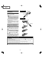
XV-Z2000
DT-400
SERVICE MANUAL
SERVICE-ANLEITUNG
SY4C6XV-Z2000
PROJECTOR
PROJEKTOR
MODELS
MODELLE
XV-Z2000
DT-400
In the interests of user-safety (Required by safety regulations in some countries) the set should be restored to its original condition and only parts identical to those specified should be used.
Im lnteresse der Benutzersicherheit (erforderliche Sicherheitsregeln in einigen Ländern) muß das Gerät in seinen
Originalzustand gebracht werden. Außerdem dürfen für die spezifizierten Bauteile nur identische Teile verwendet
werden.
SHARP CORPORATION
This document has been published to be used for
after sales service only.
The contents are subject to change without notice.
XV-Z2000
DT-400
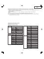
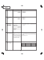
CONTENTS
Page
Page
•
•
•
•
•
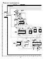
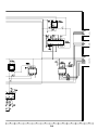
BLOCK DIAGRAM .......................................... 88
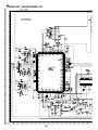
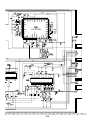
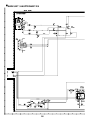
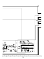
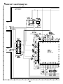
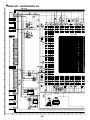
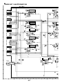
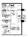
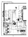
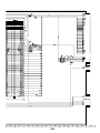
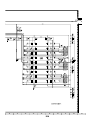
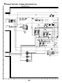
OVERALL WIRING DIAGRAM ....................... 90
WAVEFORMS ................................................. 92
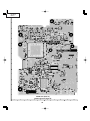
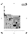
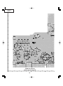
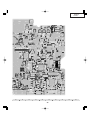
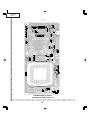
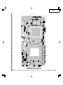
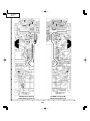
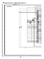
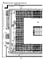
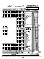
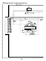
PRINTED WIRING BOARD ASSEMBLIES .... 93
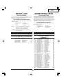
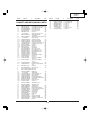
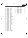
PARTS LIST
Ë ELECTRICAL PARTS ............................... 101
Ë CABINET AND MECHANICAL PARTS .... 114
Ë ACCESSORIES PARTS ........................... 118
Ë PACKING PARTS ..................................... 118
• PACKING OF THE SET ................................ 119
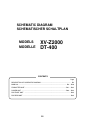
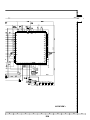
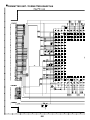
• SCHEMATIC DIAGRAM ....................... D1~D35
• SPECIFICATIONS ............................................ 3
• IMPORTANT SERVICE SAFETY
NOTES (for USA) .............................................. 4
• NOTE TO SERVICE PERSONNEL .................. 6
• OPERATION MANUAL ................................... 10
• DIMENSIONS ................................................. 16
• REMOVING OF MAJOR PARTS .................... 17
• RESETTING THE TOTAL LAMP TIMER ........ 22
• THE OPTICAL UNIT OUTLINE ....................... 24
• ELECTRICAL ADJUSTMENT ......................... 26
• TROUBLE SHOOTING TABLE ....................... 33
INHALT
Seite
Seite
• TECHNISCHE DATEN .................................... 47
• HINWEISE FÜR DAS
WARTUNGSPERSONAL ................................ 48
• BEDIENUNGSANLEITUNG ............................ 50
• ABMESSUNGEN ............................................ 56
• ENTFERNEN DER HAUPTTEILE .................. 57
• RÜCKSTELLUN DES
LAMPEN-TIMERS .......................................... 62
• BESCHREIBUNG DER OPTIK-EINHEIT ....... 64
• ELEKTRISCHE EINSTELLUNG ..................... 66
• FEHLERSUCHTABELLE ................................ 74
• BLOCKSCHALTBILD ...................................... 88
•
•
•
•
GESAMTSCHALTPLAN .................................. 90
WELLENFORMEN .......................................... 92
LEITERPLATTENEINHEITEN ........................ 93
ERSATZTEILLISTE
Ë ELEKTRISCHE BAUTEILE ....................... 101
Ë GEHÄUSE UND MECHANISCHE
BAUTEILE ................................................. 114
Ë ZUBEHÖRTEILE ....................................... 118
Ë VERPACKUNGSTEILE ............................. 118
• VERPACKEN DES GERÄTS ........................ 119
• SCHEMATISCHER SCHALTPLAN ....... D1~D35
2
XV-Z2000
DT-400
SPECIFICATIONS
Product type Projector
Model XV-Z2000, DT-400
Video system PAL/PAL 60/PAL-M/PAL-N/SECAM/NTSC 3.58/NTSC 4.43
DTV 480I/480P/540P/576I/576P/720P/1080I
Display method Single Panel Digital Micromirror Device (DMD™) by Texas Instruments
DLP panel Panel size: 0.8"
Drive method: Digital Light Processing (DLP™)
No. of dots: 921,600 dots (1,280 [H] ⋅ 720 [V])
Lens 1–1.5 ⋅ zoom lens, F2.0–2.5 f=21.3–31.6 mm
Projection lamp 275 W DC lamp
Video input signal RCA Connector: VIDEO (INPUT 4), composite video, 1.0 Vp-p, sync negative, 75 Ω
terminated
S-video input signal 4-pin Mini DIN connector (INPUT 3)
Y (luminance signal): 1.0 Vp-p, sync negative, 75 Ω terminated
C (chrominance signal): Burst 0.286 Vp-p, 75 Ω terminated
Component input signal RCA Connector
(INPUT 1, 2) Y: 1.0 Vp-p, sync negative, 75 Ω terminated
PB (CB): 0.7 Vp-p, 75 Ω terminated
PR (CR): 0.7 Vp-p, 75 Ω terminated
Analog RGB/Digital 29-pin DVI-I terminal
(INPUT 5/DIGITAL) <Digital>
Input impedance 50 Ω
Input level 250-1000 mV
<Analog>
Input impedance 75 Ω
Input level 0.7 Vp-p
Y: 1.0 Vp-p, sync negative, 75 Ω terminated
PB (CB): 0.7 Vp-p, 75 Ω terminated
PR (CR): 0.7 Vp-p, 75 Ω terminated
<Synchronization signal>
• Separate sync/Composite sync
Input level TTL level
Input impedance 1 KΩ
• Green on sync
Input level (Synchronizing input) 0.286 Vp-p
Input impedance 75 Ω
Horizontal resolution 720 TV lines (DTV 720P input)
Pixel clock 12–80 MHz
Vertical frequency 43–75 Hz
Horizontal frequency 15–70 kHz
Computer control signal 9-pin D-sub connector (RS-232C Port)
Rated voltage AC 100–240 V
Input current 3.65 A (When using AC 100 V)
Rated frequency 50/60 Hz
Power consumption 360 W (When using AC 100 V)
Power consumption (standby) 6 W (When using AC 100 V)
Heat dissipation 1,350 BTU/hour
Operating temperature 41°F to 95°F (+5°C to +35°C)
Storage temperature –4°F to 140°F (–20°C to +60°C)
Cabinet Plastic
I/R carrier frequency 38 kHz
Dimensions (approx.) 12 7/32" ⋅ 3 33/64" ⋅ 11 7/64" (310 (W) ⋅ 89 (H) ⋅ 282 (D) mm)
Weight (approx.) 9.5 lbs. (4.3 kg)
Supplied accessories Remote control, Two AA size batteries, Power cord, Lens cap (attached on the body),
Operation manual
Replacement parts Lamp unit (Lamp/cage module) (AN-K2LP), Remote control (RRMCGA334WJSA), AA
size batteries, Power cord (QACCBA036WJPZ:XV-Z2000, for U.K., Hong Kong and
Singapore), (QACCDA007WJPZ:XV-Z2000, for U.S.A., Canada and DT-400),
(QACCLA018WJPZ:XV-Z2000, for Australia and New Zealand),
(QACCVA011WJPZ:XV-Z2000, for Europe, except U.K.) Lens cap (PCAPHA021WJSA),
Operation manual (TINS-B529WJZZ:XV-Z2000, for U.S.A., and Canada),
(TINS-B530WJZZ:XV-Z2000, for European 7 Laguges),
(TINS-B531WJZZ:XV-Z2000, for Hong Kong and Korean), (TINS-B532WJZZ:DT-400)
Operation manual, for 21pin RCA Conversion Adaptor (TCADH1018CEN1:XV-Z2000,
for Europe) Video cable (QCNWGA001WJZZ:XV-Z2000, except U.S.A., Canada and
DT-400), 21pin RCA conversion adaptor (QSOCZ0361CEZZ:XV-Z2000, for Europe)
As a part of policy of continuous improvement, SHARP reserves the right to make design and
specification changes for product improvement without prior notice. The performance specification figures indicated are nominal values of production units. There may be some deviations from
these values in individual units.
3
XV-Z2000
DT-400
IMPORTANT SERVICE SAFETY NOTES (for USA)
Ë Service work should be performed only by qualified service technicians who are
thoroughly familiar with all safety checks and servicing guidelines as follows:
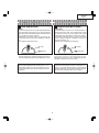
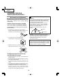
» Use an AC voltmeter with sensitivity of 5000 ohm per
volt., or higher, sensitivity to measure the AC voltage
drop across the resistor (See Diagram).
» All checks must be repeated with the AC plug
connection reversed. (If necessary, a non-polarized
adapter plug must be used only for the purpose of
completing these checks.)
Any reading of 0.3 volts RMS (this corresponds to 0.2
milliamp. AC.) or more is excessive and indicates a
potential shock hazard which must be corrected before
returning the unit to the owner.
WARNING
1. For continued safety, no modification of any circuit
should be attempted.
2. Disconnect AC power before servicing.
BEFORE RETURNING THE PROJECTOR:
(Fire & Shock Hazard)
Before returning the projector to the user, perform
the following safety checks:
1. Inspect lead wires are not pinched between the chassis
and other metal parts of the projector.
2. Inspect all protective devices such as non-metallic
control knobs, insulating materials, cabinet backs,
adjustment and compartment covers or shields,
isolation resistor-capacity networks, mechanical
insulators, etc.
3. To be sure that no shock hazard exists, check for
current leakage in the following manner:
» Plug the AC cord directly into a 100-240 volt AC outlet,
(Do not use an isolation transformer for this test).
» Using two clip leads, connect a 1.5k ohm, 10 watt
resistor paralleled by a 0.15µF capacitor in parallel
between all exposed metal cabinet parts and earth
ground.
DVM
AC SCALE
1.5k ohm
10W
0.15 µF
TEST PROBE
TO EXPOSED
METAL PARTS
CONNECT TO
KNOWN EARTH
GROUND
12345678901234567890123456789012123456789012345678901234567890121234567890123456789012345678901212
12345678901234567890123456789012123456789012345678901234567890121234567890123456789012345678901212
12345678901234567890123456789012123456789012345678901234567890121234567890123456789012345678901212
SAFETY NOTICE
AVIS POUR LA SECURITE
Many electrical and mechanical parts in DMD™
Projector have special safety-related characteristics.
These characteristics are often not evident from visual
inspection, nor can protection afforded by them be
necessarily increased by using replacement components
rated for higher voltage, wattage, etc.
Replacement parts which have these special safety
characteristics are identified in this manual; electrical
components having such features are identified by “å”
and shaded areas in the Replacement Parts Lists and
Schematic Diagrams. For continued protection,
replacement parts must be identical to those used in
the original circuit. The use of a substitute replacement
parts which do not have the same safety characteristics
as the factory recommended replacement parts shown
in this service manual, may create shock, fire or other
hazards.
De nombreuses pièces, électriques et mécaniques, dans
les projecteur à DMD™ présentent des caractéristiques
spéciales relatives à la sécurité, qui ne sont souvent pas
évidentes à vue.
Le degré de protection ne peut pas être nécessairement
augmentée en utilisant des pièces de remplacement
étalonnées pour haute tension, puissance, etc.
Les pièces de remplacement qui présentent ces
caractéristiques sont identifiées dans ce manuel;
les pièces électriques qui présentent ces particularités
sont identifiées par la marque “å” et hachurées dans la
liste des pièces de remplacement et les diagrammes
schématiques. Pour assurer la protection, ces pièces
doivent être identiques à celles utilisées dans le circuit
d’origine. L’utilisation de pièces qui n’ont pas les mêmes
caractéristiques que les pièces recommandées par l’usine,
indiquées dans ce manuel, peut provoquer des
électrocutions, incendies ou autres accidents.
WARNING: The bimetallic component has the primary
conductive side exposed. Be very careful in
handling this component when the power is on.
AVERTISSEMENT: La composante bimétallique dispose du
conducteur primaire dénudé. Faire attention
lors de la manipulation de cette
composante sous tension.
12345678901234567890123456789012123456789012345678901234567890121234567890123456789012345678901212
12345678901234567890123456789012123456789012345678901234567890121234567890123456789012345678901212
12345678901234567890123456789012123456789012345678901234567890121234567890123456789012345678901212
4
XV-Z2000
DT-400
PRECAUTIONS A PRENDRE LORS DE LA REPARATION
Ë
Ne peut effectuer la réparation qu' un technicien spécialisé qui s'est parfaitement
accoutumé à toute vérification de sécurité et aux conseils suivants.
AVERTISSEMENT
• Utiliser un voltmètre CA d'une sensibilité d'au moins
5000Ω/V pour mesurer la chute de tension en travers
de la résistance.
• Toucher avec la sonde d'essai les pièces métalliques
exposées qui présentent une voie de retour au châssis
(antenne, coffret métallique, tête des vis, arbres de
commande et des boutons, écusson, etc.) et mesurer la
chute de tension CA en-travers de la résistance. Toutes
les vérifications doivent être refaites après avoir inversé
la fiche du cordon d'alimentation. (Si nécessaire, une
prise d'adpatation non polarisée peut être utilisée dans
le but de terminer ces vérifications.)
Tous les courants mesurés ne doivent pas dépasser 0.5
mA.
Dans le cas contraire, il y a une possibilité de choc
électrique qui doit être supprimée avant de rendre le
récepteur au client.
1. N'entreprendre aucune modification de tout circuit.
C'est dangereux.
2. Débrancher le récepteur avant toute réparation.
PRECAUTION: POUR LA
PROTECTION CONTINUE CONTRE
LES RISQUES D'INCENDIE,
REMPLACER LE FUSIBLE
F701 (T6.3AH, AC250V)
VERIFICATIONS CONTRE L'INCEN-DIE ET
LE CHOC ELECTRIQUE
Avant de rendre le récepteur à l'utilisateur, effectuer
les vérifications suivantes.
1. Inspecter tous les faisceaux de câbles pour s'assurer
que les fils ne soient pas pincés ou qu'un outil ne soit
pas placé entre le châssis et les autres pièces
métalliques du récepteur.
2. Inspecter tous les dispositifs de protection comme les
boutons de commande non-métalliques, les isolants, le
dos du coffret, les couvercles ou blindages de réglage
et de compartiment, les réseaux de résistance-capacité,
les isolateurs mécaniques, etc.
3. S'assurer qu'il n'y ait pas de danger d'électrocution en
vérifiant la fuite de courant, de la facon suivante:
• Brancher le cordon d'alimentation directem-ent à une
prise de courant de 100-240V. (Ne pas utiliser de
transformateur d'isolation pour cet essai).
• A l'aide de deux fils à pinces, brancher une résistance
de 1.5 kΩ 10 watts en parallèle avec un condensateur
de 0.15µF en série avec toutes les pièces métalliques
exposées du coffret et une terre connue comme une
conduite électrique ou une prise de terre branchée à la
terre.
DVM
ECHELLE CA
1.5k ohm
10W
0.15 µF
SONDE D'ESSAI
AUX PIECES
METALLIQUES
EXPOSEES
BRANCHER A UNE
TERRE CONNUE
12345678901234567890123456789012123456789012345678901234567890121234567890123456789012345678901212
12345678901234567890123456789012123456789012345678901234567890121234567890123456789012345678901212
12345678901234567890123456789012123456789012345678901234567890121234567890123456789012345678901212
12345678901234567890123456789012123456789012345678901234567890121234567890123456789012345678901212
AVIS POUR LA SECURITE
De nombreuses pièces, électriques et mécaniques, dans les téléviseur ACL présentent des caractéristiques spéciales
relatives à la sécurité, qui ne sont souvent pas évidentes à vue. Le degré de protection ne peut pas être nécessairement
augmentée en utilisant des pièces de remplacement étalonnées pour haute tension, puissance, etc.
Les pièces de remplacement qui présentent ces caractéristiques sont identifiées dans ce manuel; les pièces électriques
qui présentent ces particularités sont identifiées par la marque " å " et hachurées dans la liste des pièces de
remplacement et les diagrammes schématiques.
Pour assurer la protection, ces pièces doivent être identiques à celles utilisées dans le circuit d'origine. L'utilisation
de pièces qui n'ont pas les mêmes caractéristiques que les pièces recommandées par l'usine, indiquées dans ce
manuel, peut provoquer des électrocutions, incendies, radiations X ou autres accidents.
12345678901234567890123456789012123456789012345678901234567890121234567890123456789012345678901212
12345678901234567890123456789012123456789012345678901234567890121234567890123456789012345678901212
12345678901234567890123456789012123456789012345678901234567890121234567890123456789012345678901212
12345678901234567890123456789012123456789012345678901234567890121234567890123456789012345678901212
5
XV-Z2000
DT-400
NOTE TO SERVICE
NOTE POUR LE PERSONNEL
PERSONNEL
D’ENTRETIEN
123456789012345678901234567890121234567890123456 123456789012345678901234567890121234567890123456
123456789012345678901234567890121234567890123456
123456789012345678901234567890121234567890123456
123456789012345678901234567890121234567890123456
123456789012345678901234567890121234567890123456
UV-RADIATION PRECAUTION
123456789012345678901234567890121234567890123456
123456789012345678901234567890121234567890123456
PRECAUTION POUR LES RADIATIONS UV
123456789012345678901234567890121234567890123456
123456789012345678901234567890121234567890123456
The light source, metal halide lamp, in the projector
emits small amounts of UV-Radiation.
La source de lumière, la lampe métal halide, dans
le projecteur émet de petites quantités de
radiation UV.
AVOID DIRECT EYE AND SKIN EXPOSURE.
EVITEZ TOUTE EXPOSITION DIRECTE DES
YEUX ET DE LA PEAU.
To ensure safety please adhere to the following:
Pour votre sécurité, nous vous prions de respecter
les points suivants:
1. Be sure to wear sun-glasses when servicing the
projector with the lamp
turned “on” and the top
enclosure removed.
1. Toujours porter des lunettes de soleil lors d’un entretien
du projecteur
avec la lampe allumée
et le haut du coffret retiré.
2. Do not operate the lamp outside of the lamp housing.
2. Ne pas faire fonctionner la lampe à l’extérieur du boîtier
de lampe.
3. Do not operate for more than 2 hours with the enclosure
removed.
3. Ne pas faire fonctionner plus de 2 heures avec le coffret
retiré.
UV-Radiation and Medium Pressure
Lamp Precautions
Précautions pour les radiations UV
et la lampe moyenne pression
1. Be sure to disconnect the AC plug when replacing the
lamp.
2. Allow one hour for the unit to cool down before
servicing.
3. Replace only with same type lamp. Type AN-K2LP
rated 275W.
4. The lamp emits small amounts of UV-Radiation, avoid
direct-eye contact.
5. The medium pressure lamp involves a risk of explosion.
Be sure to follow installation instructions described
below and handle the lamp with care.
1. Toujours débrancher la fiche AC lors du remplacement
de la lampe.
2. Laisser l’unité refroidir pendant une heure avant de
procéder à l’entretien.
3. Ne remplacer qu’avec une lampe du même type. Type
AN-K2LP, caractéristique 275W.
4. La lampe émet de petites quantités de radiation UVéviter tout contact direct avec les yeux.
5. La lampe moyenne pression implique un risque
d’explosion. Toujours suivre les instructions
d’installation décrites ci-dessous et manipuler la lampe
avec soin.
6
XV-Z2000
DT-400
123456789012345678901234567890121234567890123456
123456789012345678901234567890121234567890123456
123456789012345678901234567890121234567890123456
123456789012345678901234567890121234567890123456
UV-RADIATION PRECAUTION (Continued)
123456789012345678901234567890121234567890123456
123456789012345678901234567890121234567890123456
PRECAUTION POUR LES RADIATIONS UV (Suite)
123456789012345678901234567890121234567890123456
123456789012345678901234567890121234567890123456
Remplacement de la lampe
Lamp Replacement
Note:
Remarque:
Since the lamp reaches a very high temperature during
units operation replacement of the lamp should be
done at least one hour after the power has been turned
off. (to allow the lamp to cool off.)
Installing the new lamp, make sure not to touch the
lamp (bulb) replace the lamp by holding its reflector
2.
[Use original replacement only.]
Comme la lampe devient très chaude pendant le
fonctionnement de l’unité, son remplacement ne doit
être effectué au moins une heure après avoir coupé
l’alimentation (pour permettre à la lampe de refroidir).
En installant la nouvelle lampe, s’assurer de ne pas
toucher la lampe (ampoule). Remplacer la lampe en
tenant son réflecteur 2.
[N’utiliser qu’un remplacement d’origine.]
1 Lampe
1 Lamp
2 Reflecteur
2 Reflector
DANGER ! –– Never turn the power on without the
lamp to avoid electric-shock or damage of the devices
since the stabilizer generates high voltages at its start.
DANGER ! –– Ne jamais mettre sous tension sans la
lampe pour éviter un choc électrique ou des
dommages des appareils car le stabilisateur génère
de hautes tensions à sa mise en route.
Since small amounts of UV-radiation are emitted
from an opening between the exhaust fans, it is recommended to place the cap of the optional lens on
the opening during servicing to avoid eye and skin
exposure.
Comme de petites quantités de radiation UV sont
émises par une ouverture entre les ventilateurs aspirants, il est recommandé de placer le capuchon de
l’optique optionnelle sur l’ouverture pendant l’entretien
pour éviter une exposition des yeux et la peau.
7
XV-Z2000
DT-400
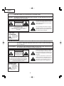
WARNING:
High brightness light source, do not stare into the beam of light, or view directly. Be especially
careful that children do not stare directly in to the beam of light.
WARNING:
TO REDUCE THE RISK OF FIRE OR ELECTRIC SHOCK, DO NOT EXPOSE THIS UNIT TO
MOISTURE OR WET LOCATIONS.
CAUTION
The lighting flash with arrowhead within a
triangle is intended to tell the user that
parts inside the product are risk of electric
shock to persons.
RISK OF ELECTRIC SHOCK.
DO NOT REMOVE SCREWS
EXCEPT SPECIFIED USER
SERVICE SCREW.
CAUTION: TO REDUCE THE RISK OF ELECTRIC SHOCK,
DO NOT REMOVE CABINET.
NO USER-SERVICEABLE PARTS EXCEPT LAMP UNIT.
REFER SERVICING TO QUALIFIED SERVICE
PERSONNEL.
The exclamation point within a triangle is
intended to tell the user that important
operating and servicing instructions are in
the manual with the projector.
CAUTION
(POWER Unit)
6.3A 250V
For continued
protection against a
risk of fire, replace
only with same type
T6.3AH, AC250V
fuse.(F701)
12345678901234567890123456789012123456789012345678901234567890121234567890123456789012345678901212
12345678901234567890123456789012123456789012345678901234567890121234567890123456789012345678901212
12345678901234567890123456789012123456789012345678901234567890121234567890123456789012345678901212
AVERTISSEMENT: Source lumineuse de grande intensité. Ne pas fixer le faisceau lumineux ou le regarder
directement. Veiller particulièrement à éviter que les enfants ne fixent directement le
faisceau lumineux.
AVERTISSEMENT: AFIN D’EVITER TOUT RISQUE D’INCENDIE OU D’ELECTROCUTION, NE PAS PLACER
CET APPAREIL DANS UN ENDROIT HUMIDE OU MOUILLE.
ATTENTION
L’éclair terminé d’une flèche à l’intérieur
d’un triangle indique à l’utilisateur que les
pi‘eces se trouvant dans l’appareil sont
susceptibles de provoquer une décharge
électrique.
RISQUE
D’ÉLECTROCUTION. NE
PASR ETIRER LES VIS Á
L’EXCEPTION DE LA VIS DE
REPARATION UTILISATEUR
SPECIFIEES
Le point d’exclamation à l’intérieur d’un
triangle indique à l’utilisateur que les
instructions de fonctionnement et
d’entretien sont détaillées dans les
documents fournis avec le projecteur.
ATTENTION: POUR EVITER TOUT RISQUE
D’ELECTROCUTION, NE PAS RETIRER LE CAPOT.
AUCUNE DES PIECES INTERIEURES N’EST REPARABLE
PAR L’UTILISATEUR, A L’EXCEPTION DE L’UNITE DE
LAMPE. POUR TOUTE REPARATION, S’ADRESSER A UN
TECHNICIEN D’ENTRETIEN QUALIFIE.
PRECAUTION
(Unité de PUTSSANCE)
6.3A 250V
Pour une protection
continue contre un
risques d’incendie, ne
remplacer qu’avec un
fusible T6.3AH,
AC250V du même
type. (F701)
8
XV-Z2000
DT-400
Precautions for using lead-free solder
1 Employing lead-free solder
"PWBs" of this model employs lead-free solder. The LF symbol indicates lead-free solder, and is attached on the
PWBs and service manuals. The alphabetical character following LF shows the type of lead-free solder.
Example:
LFa
Indicates lead-free solder of tin, silver and copper.
2 Using lead-free wire solder
When fixing the PWB soldered with the lead-free solder, apply lead-free wire solder. Repairing with conventional
lead wire solder may cause damage or accident due to cracks.
As the melting point of lead-free solder (Sn-Ag-Cu) is higher than the lead wire solder by 40°C, we recommend you
to use a dedicated soldering bit, if you are not familiar with how to obtain lead-free wire solder or soldering bit,
contact our service station or service branch in your area.
3 Soldering
As the melting point of lead-free solder (Sn-Ag-Cu) is about 220°C which is higher than the conventional lead solder
by 40°C, and as it has poor solder wettability, you may be apt to keep the soldering bit in contact with the PWB for
extended period of time. However, since the land may be peeled off or the maximum heat-resistance temperature
of parts may be exceeded, remove the bit from the PWB as soon as you confirm the steady soldering condition.
Lead-free solder contains more tin, and the end of the soldering bit may be easily corroded. Make sure to turn on
and off the power of the bit as required.
If a different type of solder stays on the tip of the soldering bit, it is alloyed with lead-free solder. Clean the bit after
every use of it.
When the tip of the soldering bit is blackened during use, file it with steel wool or fine sandpaper.
Be careful when replacing parts with polarity indication on the PWB silk.
Lead-free wire solder for servicing
Part No.
ZHNDAi123250E
ZHNDAi126500E
ZHNDAi12801KE
★
J
J
J
Description
φ0.3mm
250g(1roll)
φ0.6mm
500g(1roll)
φ1.0mm
1kg(1roll)
9
Code
BL
BK
BM
XV-Z2000
DT-400
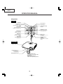
OPERATION MANUAL
Projector
Top View
ON button
Turn the power on.
Power indicator
STANDBY button
Lamp indicator
Put the projector into standby
mode.
Temperature warning
indicator
RESIZE button
Switch the picture display
(STRETCH, SIDE BAR, etc.).
ZOOM/FOCUS button
Adjust the projected image
size or adjust the focus.
ENTER button
Set items selected or
adjusted on the menu.
UNDO button
Undo an operation or
returning to the previous
display.
INPUT button
Switch input mode 1, 2, 3, 4,
5 or DIGITAL.
MENU button
Adjustment buttons
('/"/\/|)
Display adjustment and
setting screens.
Select menu items and other
settings.
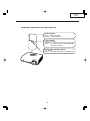
Front View
Remote control sensor
Front adjustment foot
(on the bottom of
the projector)
HEIGHT ADJUST button
• Attaching the lens cap
Push the lens cap on until it clicks
into position.
• Removing the lens cap
Pull the lens cap directly outward.
10
XV-Z2000
DT-400
About the Indicators on the Projector
Power indicator
Red on ... Normal (Standby)
Green on ... Normal (Power on)
Lamp indicator
Green on ... Normal
Green blinks ... The lamp is warming up or shutting down.
Red on ... The lamp has been shut down abnormally or
needs to be changed.
Temperature warning indicator
Off ... Normal
Red on ... The internal temperature is abnormally high.
11
XV-Z2000
DT-400
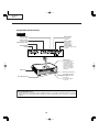
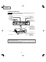
Projector (Rear View)
Terminals
INPUT 2 terminal
INPUT 4 terminal
Component signals.
INPUT 1 terminal
Connect video
equipment.
Component signals.
INPUT 3 terminal
Connect video
equipment with an
S-video terminal.
Digital input type switch
INPUT 5/DIGITAL
terminal
RS-232C terminal
Control the projector using a
computer.
Exhaust vent
The speed and pitch of
the cooling fan may
change during operation
in response to internal
temperature changes.
This is normal operation
and does not indicate a
malfunction.
Intake vent
Remote control sensor
Kensington Security
Standard connector
Rear adjustment feet
AC socket
Connect the supplied
Power cord.
Using the Kensington Lock
• This projector has a Kensington Security Standard connector for use with a Kensington MicroSaver Security
System. Refer to the information that came with the system for instructions on how to use it to secure the
projector.
12
XV-Z2000
DT-400
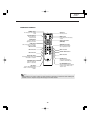
Remote Control
STANDBY button
Put the projector into standby
mode.
ON button
Turn the power on.
KEYSTONE button
Enter the Keystone
Correction mode.
MENU button
Display adjustment and setting
screens.
ENTER button
Adjustment buttons
('/"/\/|)
Set items selected or
adjusted on the menu.
UNDO button
Undo an operation or returning to
the previous display.
ZOOM/FOCUS button
Adjust the projected image
size or adjusting the focus.
INPUT 1 button
INPUT 2 button
INPUT 3 button
DIGITAL INPUT button
INPUT 4 button
INPUT 5 button
AUTO SYNC button
Automatically adjust images when
connected to a computer.
RESIZE button
Switch the picture display
(STRETCH, SIDE BAR, etc.).
RGB/COMP. button
Switch the signal type
(RGB or Component).
PICTURE MODE button
Select the picture setting (Memory)
stored in “Picture Mode” on the
“Picture” menu.
IRIS button
Switch “HIGH BRIGHTNESS
MODE” or “HIGH CONTRAST
MODE”.
Note
• All the buttons on the remote control are made of luminous material that is visible in the dark. Visibility will
diminish over time. Exposure to light will recharge the luminous buttons.
13
XV-Z2000
DT-400
Remote control sensor
Front View
30°
Usable Range
30°
Remote
control
signal
transmitters
The remote control can be used to control the
projector within the ranges shown in the
illustration.
30°
23' (7 m)
Note
• The signal from the remote control can be reflected off a screen for easy operation. However, the effective distance of the signal may
differ depending on the screen material.
Remote control
Rear View
Remote control sensor
30°
When using the remote control:
• Ensure not to drop, expose to moisture or high
temperature.
• The remote control may malfunction under a
fluorescent lamp. In this case, move the projector away from the fluorescent lamp.
30°
23' (7 m)
30°
Remote
control
signal
transmitters
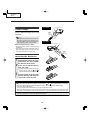
Inserting the Batteries
Remote control
1
Pull down the tab on the cover
and remove the cover towards
the direction of the arrow.
2
Insert the included batteries
(two “AA” size).
• Insert the batteries making sure the poand
larities correctly match the
marks inside the battery compartment.
3
Insert the lower tab of the cover
into the opening, and lower the
cover until it clicks in place.
Incorrect use of the batteries may cause them to leak or explode. Please follow the precautions below.
Caution
• Insert the batteries making sure the polarities correctly match the
and
marks inside the battery compartment.
• Batteries of different types have different properties, therefore do not mix batteries of different types.
• Do not mix new and old batteries.
This may shorten the life of new batteries or may cause old batteries to leak.
• Remove the batteries from the remote control once they have run out, as leaving them in can cause them to leak.
Battery fluid from leaked batteries is harmful to skin, therefore ensure to first wipe them and then remove them using a cloth.
• The batteries included with this projector may run down in a short period, depending on how they are kept.
Ensure to replace them as soon as possible with new batteries.
14
XV-Z2000
DT-400
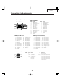
Connection Pin Assignments
DVI-I (INPUT 5) port : 29 pin connector
• DVI Digital INPUT
~
9
Pin No.
1
2
3
4
5
6
7
8
9
10
11
12
13
14
15
16
∞ ∞ ∞ ∞ ∞ ∞ ∞ ∞ ∞∞ ∞ ∞ ∞ ∞ ∞ ∞ ∞ ∞
1 2
~ ∞∞∞∞ 7 8
∞∞∞∞
C1
C2
C4
C5
C3
17
24
18
~ ∞ ∞ ∞ ∞ 23
∞∞∞∞
• DVI Analog RGB Input
Pin No.
1
2
3
4
5
6
7
8
9
10
11
12
13
14
15
Signal
Not connected
Not connected
Not connected
Not connected
Not connected
DDC clock
DDC data
Vertical sync
Not connected
Not connected
Not connected
Not connected
Not connected
+5V power
Ground
Pin No.
16
17
18
19
20
21
22
23
24
C1
C2
C3
C4
C5
Signal
Pin No.
T.M.D.S data 2–
16
T.M.D.S data 2+
17
T.M.D.S data 2 shield
18
Not connected
19
Not connected
20
DDC clock
21
DDC data
22
Not connected
23
T.M.D.S data 1–
24
T.M.D.S data 1+
C1
T.M.D.S data 1 shield
C2
Not connected
C3
Not connected
C4
+5V power
C5
Ground
Signal
Hot plug detection
T.M.D.S data 0–
T.M.D.S data 0+
T.M.D.S data 0 shield
Not connected
Not connected
T.M.D.S clock shield
T.M.D.S clock+
T.M.D.S clock–
Not connected
Not connected
Not connected
Not connected
Ground
• DVI Analog Component Input
Signal
Hot plug detection
Not connected
Not connected
Not connected
Not connected
Not connected
Not connected
Not connected
Not connected
Analog input Red
Analog input Green
Analog input Blue
Horizontal sync
Ground
Pin No.
1
2
3
4
5
6
7
8
9
10
11
12
13
14
15
Signal
Not connected
Not connected
Not connected
Not connected
Not connected
Not connected
Not connected
Not connected
Not connected
Not connected
Not connected
Not connected
Not connected
Not connected
Ground
Pin No.
16
17
18
19
20
21
22
23
24
C1
C2
C3
C4
C5
Signal
Not connected
Not connected
Not connected
Not connected
Not connected
Not connected
Not connected
Not connected
Not connected
Analog input PR/CR
Analog input Y
Analog input PB/CB
Not connected
Ground
RS-232C Port: 9-pin D-sub male connector
9 8 76
54 321
Pin No.
1
2
3
4
5
6
7
8
9
Signal
RD
SD
SG
Name
Receive Data
Send Data
Reserved
Signal Ground
Reserved
Reserved
Reserved
15
I/O
Input
Output
Reference
Not connected
Connected to internal circuit
Connected to internal circuit
Connected to internal circuit
Connected to internal circuit
Connected to internal circuit
Connected to internal circuit
Connected to internal circuit
Not connected
XV-Z2000
DT-400
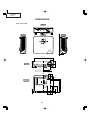
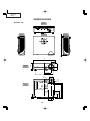
DIMENSIONS
Units: inches (mm)
Side View
/16 (1.5)
Rear View
Side View
9/64
(3.25)
11 7/64 (282)
1
Top View
12 7/32 (310)
2 3/16
(55.5)
3 33/64 (89)
/64 (5)
Front View
1 59/64
(48.5)
2 11/64 (55.05)
13
3 15/16 (99.95)
5 7/64
5 7/64 (129.5)
(129.5)
7
1 5/32 1 /32
(29.1) (30.9)
M4
M4
5
9
/16 (14)
/8 (15.5)
1 7/32
1 3/4
(44.1) (30.9)
16
8 7/8 (225.3)
M4
8 9/32 (210.3)
M4
4 3/16 (106.3)
Bottom View
XV-Z2000
DT-400
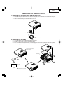
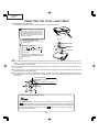
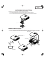
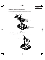
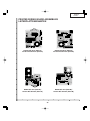
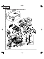
REMOVING OF MAJOR PARTS
1. Removing the lamp unit cover and the lamp unit
1-1. Loosen the lamp unit cover fixing screw, slide the lamp unit cover in allow direction and lift off the lamp unit
cover.
1-2. Loosen 2 lamp unit fixing screws and lift off the lamp unit.
Lamp Unit
1-3
Lamp Unit Cover
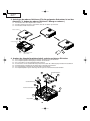
2. Removing the top body
2-1.
2-2.
2-3.
2-4.
1-2
Insert thick paper such as a postcard under the lens barrel.
Remove 7 fixing screws for the top and bottom bodies.
Press and hold the areas (marked with *) and disengage the claws on the top body to remove the top body.
Top Body
Draw out a postcard.
To protect the lens barrel
against scratches.
2-3
2-2
Bottom Body
2-1
2-2
2-4
Short side
(10cm)
Long side
(15cm)
Thick paper such as a postcard.
17
XV-Z2000
DT-400
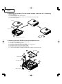
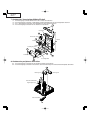
3. Attaching the top body (For the screws to apply, refer back to "2. Removing
the top body".)
3-1. Place the postcard over the lens barrel.
3-2. Place the top body in position. Make sure the four hooks are tightly caught.
3-3. Draw out the postcard.
Top Body
3-2
Bottom Body
3-1
3-3
Thick paper such as postcard
4. Removing the main PWB unit and the peripheral units
4-1.
4-2.
4-3.
4-4.
4-5.
4-6.
4-7.
Remove 4 main PWB fixing screws (terminal side).
Remove 9 main PWB fixing screws.
Remove 12 connectors from the main PWB.
Pull out the switch bracket connector and remove 3 fixing screws.
Remove the fixing screw for the front R/C PWB.
Remove 2 fixing screws for the button holder unit.
Lift off the main PWB in an oblique direction from the optical mechanism unit side.
Main PWB
4-3
4-2
4-4
Switch Bracket
4-5
4-7
Front-R/C Unit
4-1
4-6
Button Holder
18
XV-Z2000
DT-400
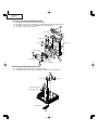
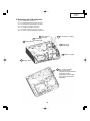
5. Removing the optical mechanism unit
5-1.
5-2.
5-3.
5-4.
5-5.
Remove the fixing screw from the PWB bracket.
Remove 2 fixing screws for the ballast output socket, and remove the ballast output socket.
Remove 5 fixing screws for the optical mechanism unit, and remove the optical mechanism unit.
Remove the duct, pulling up the optical mechanism unit.
Remove the speaker cover.
5-2
5-3
5-4
Duct
Optical Mechanism Unit
5-1
PWB Bracket
Ballast Output Socket
5-5
Speaker Cover
5-3
6. Removing the power/ballast unit
6-1. Remove 3 fixing screws for the power/ballast unit.
6-1
Power/Ballast Unit
6-1
19
XV-Z2000
DT-400
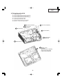
7. Removing the power/ballast unit
7-1.
7-2.
7-3.
7-4.
Remove the fixing screw for the rear-R/C PWB.
Remove 4 fixing screws, 4 WH bosses and the edge saddle for the ballast unit.
Remove 11 fixing screws and 5 WH bosses for the power unit.
7-3
Remove 4 fixing screws for the fan.
Power PWB
7-3
7-1
7-3
Rear-R/C PWB
7-3
7-4
Power Unit
Air Flow
7-3
7-2
Fan
Ballast PWB
7-2
7-3
Edge saddle
7-3
Ballast Unit
7-2
8. Removing the peripheral units
8-1. Remove 4 fixing screws for the front adjuster foot.
8-2. Remove 8 bracket fixing screws and remove the bracket-A and bracket-B.
8-2
Bracket-A
Bracket-B
8-1
Front Adjuster Holder
Height Adjust Button
Front Adjuster Foot
20
XV-Z2000
DT-400
9. Fixing the earth shield
9-1.
9-2.
9-3.
9-4.
9-5.
9-6.
9-7.
9-8.
Install the four nuts.
Fit the reinforcement (bracket-A) in position.
Place the earth shield (L) as specified.
Fit the reinforcement (bracket-B) in position.
Tighten up the four M3 screws.
Tighten up the four M4 screws.
Place the earth shield (S) as specified.
Melt the 17 pins of the earth shield.
9-6 M4 screw (4 locations)
9-5 M3 screw (4 locations)
9-4 Reinforcement
9-3 Earth Shield (L)
(Bracket-B)
9-1 Nut (4 locations)
9-2 Reinforcement
(Bracket-A)
9-7 Earth Shield (S)
9-8 Melt the 17 pins.
Precaution
*Melt the pins with a soldering
iron to fix the earth shield.
Finally check for loosenes.
21
XV-Z2000
DT-400
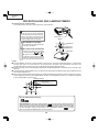
RESETTING THE TOTAL LAMP TIMER
● Resetting the total lamp timer
When replacing the lamp, reset the total lamp timer in the procedure below.
Info
• Make sure to reset the lamp timer only
when replacing the lamp. If you reset the
lamp timer and continue to use the same
lamp, this may cause the lamp to become
damaged or explode.
1
2
AC socket
ON button
Connect the power cord.
• Plug the power cord into the AC socket
of the projector.
ENTER button
Reset the lamp timer.
• Press
,
,
, \,
\/| buttons
UNDO button
and | on the
projector in order, and then press
on
INPUT button
the projector.
• “LAMP 0000H” is displayed on the lower
left of the screen, indicating that the lamp
timer is reset.
Lamp
■ It is recommended that the lamp (sold separately) be replaced when the remaining lamp life becomes 5% or less,
or when you notice a significant deterioration in the picture and color quality. The lamp life (percentage) can be
checked with the on-screen display.
■ Purchase a replacement lamp of type AN-K2LP from your place of purchase, nearest Sharp Projector Dealer or
Service Center.
■ The warning lights (ON/STANDBY button, lamp indicator and temperature warning indicator) on the projector
indicate problems inside the projector.
■ If a problem occurs, either the temperature warning indicator or the lamp indicator will illuminate red, and the
projector will enter the standby mode. After the projector has entered the standby mode, follow the procedures
given below.
Maintenance Indicators
Power indicator
Lamp indicator
Temperature warning indicator
About the temperature warning indicator
If the temperature inside the projector increases, due to blockage of the air vents, or the setting location,
“
” will illuminate in the lower left corner of the picture. If the temperature keeps on rising, the lamp will
turn off and the temperature warning indicator will blink, the cooling fan will run for a further 90 seconds, and
” appears, ensure to perform the measures
then the projector will enter the standby mode. After “
described on operation manual.
22
XV-Z2000
DT-400
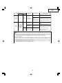
Maintenance indicator
Abnormal
Normal
Problem
Cause
Possible solution
• Relocate the projector to an area
• Blocked air intake
Temperature
warning
indicator
Lamp
indicator
Off
with proper ventilation
The internal
• Take the projector to your nearest
Red on
temperature is
• Cooling fan breakSharp Authorized Projector Dealer
(Standby)
abnormally high.
down
or Service Center for repair.
• Internal circuit failure
• Clogged air intake
• Clean the exhaust and intake
vents.
Green on
Red on
Green blinks
when the lamp
is warming up
or shutting
down.
Red on
(Standby)
The lamp does
not illuminate.
• The lamp is shut
Time to change
the lamp.
• Remaining lamp life
The lamp does
not illuminate.
down abnormally.
• Disconnect the power cord from
the AC outlet, and then connect it
again.
• Carefully replace the lamp.
becomes 5% or less. • Take the projector to your nearest
Sharp Authorized Projector Dealer
or Service Centerfor repair.
• Burnt-out lamp
• Lamp circuit failure • Please exercise care when
replacing the lamp.
Info
• If the temperature warning indicator illuminates and the projector enters the standby mode, check whether
any of the ventilation holes are blocked and then try turning the power back on. Wait until the projector has
cooled down completely before plugging in the power cord and turning the power back on.
(At least 10 minutes.)
• If the power is turned off for a brief moment due to power outage or some other cause while using the
projector, and the power supply recovers immediately after that, the lamp indicator will illuminate in red
and the lamp may not be lit. In this case, unplug the power cord from the AC outlet, replace the power
cord in the AC outlet and then turn the power on again.
• Do not unplug the power cord after the projector has entered the standby mode and while the cooling fan
is running. The cooling fan runs for about 90 seconds.
23
XV-Z2000
DT-400
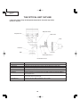
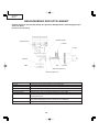
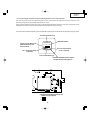
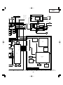
THE OPTICAL UNIT OUTLINE
Layout for proper setup of the optical components and parts (top view)
(Schematic diagram)
Reflection mirror
Projection lens
Color wheel
Lamp
Field lens
DMD
Rod
UV Filter
Illumination lenses 1
Illumination lenses 2
Item
Lamp
Color wheel
Rod
Illumination lenses
Reflection mirror
Field lens
DMD
Projection lens
Function
Light source. DC high-pressure mercury lamp.
Splits light from the light source into R, G, B and W through a color filter.
Assures uniform light ray.
Focus light from the rod on DMD.
Reflects light from the illumination lenses toward DMD.
Focuses light from the reflection mirror on DMD and then the light from DMD to
the projection lens.
Turns the internal micromirror ON/OFF at the rate of color component of each dot
of the input source to reflect light.
Enlarges light from DMD and projects it on a screen.
24
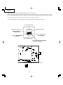
XV-Z2000
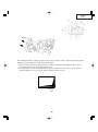
DT-400
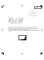
Air Flow
After replacing the DMD, if shading is present on the screen as shown in Figure 1, adjust the lighting area of the
DMD by turning the adjustment screws for the optical engine.
1. Loosen the fixing screw for the adjustment lever 1. Adjust the lighting area by adjustment lever 2 and
then tighten the fixing screw for the adjustment lever 1.
2. If the lightening area cannot be adjusted after the above procedure, loosen the fixing screw 3, adjust the
area with adjustment screws 4 and 5, and then tighten the fixing screw 3.
Shading
Fig. 1
25
XV-Z2000
DT-400
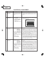
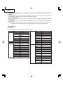
ELECTRICAL ADJUSTMENT
No.
Adjusting point
Adjusting conditions
Adjusting procedure
1
Initialization of
EEPROM
1. Turn on the power (the
lamp lights up) and warm
up the system for 15 minutes.
1. Carry out the following setting.
Using the remote controller or press S2002 to
enter the process mode, and execute SS2 on SS
menu.
2
Adjustment of
CW index
1. Input the gradation pattern of RGB.
(SVGA60Hz or XGA)
2. S e l e c t t h e f o l l o w i n g
group and subject.
Group: DLP
Subject: INDEX DELAY
1. Select subject and make adjustment so that the
lamp gradation patterns of R, G and B should be
smooth without noise.
R
G
B
3-1
R-Bright / RContrast
1. Group: AD
Subject: R-BRIGHT
(Black level)
R-CONTRAST
(White level)
2. Feed the window pattern
signal containing 91%
(0.64Vp-p) R signal and
0% level.
(Process/Gamma interaction)
(SVGA or XGA)
Input 5 RGB input
1. Observe the 0% window pattern chromaticity on
CA100.
2. Starting with a bit dropout screen, vary the RBright setting until the bright red "x" setting turns
toward the black tone and stays there. Now raise
the setting by one point and adjust to the point
where the first bit dropout is encountered (the
setting changes over 5/1000).
3. Observe the 91% R signal chromaticity on CA100.
4. Starting with a bit dropout screen, vary the RContrast setting until the bright red "x" setting
turns toward the black tone and stays there. Now
raise the setting by one point and adjust to the
point where the first bit dropout is encountered
(the setting changes over 5/1000).
3-2
G-Bright / GContrast
1. Group: AD
Subject: G-BRIGHT
(Black level)
G-CONTRAST
(White level)
2. Feed the window pattern
signal containing 91%
(0.64Vp-p) G signal and
0% level.
(Process/Gamma interaction)
(SVGA or XGA)
Input 5 RGB input
1. Observe the 0% window pattern chromaticity on
CA100.
2. Starting with a bit dropout screen, vary the GBright setting until the bright green "y" setting
turns toward the black tone and stays there. Now
raise the setting by one point and adjust to the
point where the first bit dropout is encountered
(the setting changes over 5/1000).
3. Observe the 91% G signal chromaticity on CA100.
4. Starting with a bit dropout screen, vary the RContrast setting until the bright green "y" setting turns toward the black tone and stays there.
Now raise the setting by one point and adjust to
the point where the first bit dropout is encountered (the setting changes over 5/1000).
26
XV-Z2000
DT-400
No.
Adjusting point
Adjusting conditions
Adjusting procedure
3-3
B-Bright / BContrast
1. Group: AD
Subject: B-BRIGHT
(Black level)
B-CONTRAST
(White level)
2. Feed the window pattern
signal containing 91%
(0.64Vp-p) B signal and
0% level.
(Process/Gamma interaction)
(SVGA or XGA)
Input 5 RGB input
1. Observe the 0% window pattern chromaticity on
CA100.
2. Starting with a bit dropout screen, vary the BBright setting until the bright blue "y" setting turns
toward the black tone and stays there. Now raise
the setting by one point and adjust to the point
where the first bit dropout is encountered (the
setting changes over 5/1000).
3. Observe the 91% G signal chromaticity on CA100.
4. Starting with a bit dropout screen, vary the BContrast setting until the bright blue "y" setting
turns toward the black tone and stays there. Now
raise the setting by one point and adjust to the
point where the first bit dropout is encountered
(the setting changes over 5/1000).
4-1
DTV Bright/
Contrast
Adjustment
1. Group: DTV
Subject: BRIGHT
(Black level)
CONTRAST
(White level)
1. Check the fixed value.
Contrast: 5
Bright: 55
4-2
DTV R-Bright/
Contrast
Adjustment
1. Group: DTV
Subject: R-BRIGHT
(Black level)
R-CONTRAST
(White level)
(Process/GAMMA interaction Input5 Color difference input)
1. Observe the 0%black window pattern chromaticity on CA100.
2. Starting with a bit dropout screen, vary the Bright
setting until the bright red "x" setting turns toward the black tone and stays there. Now raise
the setting by one point and adjust to the point
where the first bit dropout is encountered (the
setting changes over 5/1000).
3. Observe the 100% W window pattern chromaticity on CA100.
4. Starting with a bit dropout screen, vary the Contrast setting until the bright red "x" setting turns
toward the black tone and stays there. Now raise
the setting by one point and adjust to the point
where the first bit dropout is encountered (the
setting changes over 5/1000).
4-3
DTV G-Bright/
Contrast
Adjustment
1. Group: DTV
Subject:G-BRIGHT
(Black level)
G-CONTRAST
(White level)
(Process/GAMMA interaction Input5 Color difference input)
1. Observe the 0%black window pattern chromaticity on CA100.
2. Starting with a bit dropout screen, vary the Bright
setting until the bright green "y" setting turns
toward the black tone and stays there. Now raise
the setting by one point and adjust to the point
where the first bit dropout is encountered (the
setting changes over 5/1000).
3. Observe the 100% W window pattern chromaticity on CA100.
4. Starting with a bit dropout screen, vary the Contrast setting until the bright green "y" setting turns
toward the black tone and stays there. Now raise
the setting by one point and adjust to the point
where the first bit dropout is encountered (the
setting changes over 5/1000).
27
XV-Z2000
DT-400
No.
Adjusting point
Adjusting conditions
Adjusting procedure
4-4
DTV B-Bright/
Contrast
Adjustment
1. Group: DTV
Subject: B-BRIGHT
(Black level)
B-CONTRAST
(White level)
(Process/GAMMA interaction Input5 Color difference input)
1. Observe the 0%black window pattern chromaticity on CA100.
2. Starting with a bit dropout screen, vary the Bright
setting until the bright blue "y" setting turns toward the black tone and stays there. Now raise
the setting by one point and adjust to the point
where the first bit dropout is encountered (the
setting changes over 5/1000).
3. Observe the 100% W window pattern chromaticity on CA100.
4. Starting with a bit dropout screen, vary the Contrast setting until the bright blue "y" setting turns
toward the black tone and stays there. Now raise
the setting by one point and adjust to the point
where the first bit dropout is encountered (the
setting changes over 5/1000).
5
DTV Tint
1. Group: DTV
Subject: Tint
1. Check the fixed value.
Tint: 8
6
DTV Color
Saturation
Level
1. Group: DTV
Subject: Color
1. Check the fixed value.
Color: 4
7
DVD Bright/
Contrast
Adjustment
1. Group: DVD
Subject: BRIGHT
(Black level)
CONTRAST
(White level)
1. Check the fixed value.
Contrast: 5
Bright: 55
8
DVD Tint
1. Group: DVD
Subject: Tint
1. Check the fixed value.
Tint: 4
9
DTV Color
Saturation Level
1. Group: DVD
Subject: Color
1. Check the fixed value.
Color: 5
10
Video Bright/
Contrast
Adjustment
1. Group: VIDEO
Subject: BRIGHT
(Black level)
CONTRAST
(White level)
1. Check the fixed value.
Contrast: 5
Bright: 55
11
VIDEO Tint
1. Group: VIDEO
Subject: N-Tint
P-Tint
S-Tint
1. Check the fixed values.
N-Tint: 8
P-Tint: 4
S-Tint: 4
12
VIDEO Color
Saturation Level
1. Group: VIDEO
Subject: N-Color
P-Color
S-Color
1. Check the fixed values.
N-Color: 7
P-Color: 4
S-Color: 7
28
XV-Z2000
DT-400
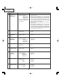
No.
Adjusting point
Adjusting conditions
Adjusting procedure
13
DVD White
balance
(Auto
adjustment)
1. Feed the component 75%
gray scale signal.
2. Group: PIXEL
Subject:R-GAIN (R)
B-GAIN (B)
Input 5 Color
difference input
1. Adjust the white balance by controlling R-GAIN and
B-GAIN.
(Adjust x=298 and y=319.)
14
DLP voltage
adjustment
1. Read the DLP-listed voltage rank.
2. Make the switch setting
corresponding to the readout rank.
(on the Formatter PWB)
1. Make this adjustment when the DLP chip has
been replaced or the combination of DLP chip
and Formatter PWB has been changed.
Ranking: D E
15
Factory setting
1. Make the following settings.
Destination
29
Process adjustment Remote controller setting
Europe
SS3
Factory setting 3
North America
SS4
Factory setting 4
XV-Z2000
DT-400
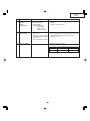
* Precautions in setting up the DMD (Digital Micromirror Device) unit
Before connecting the formatter PWB to the optical engine, take the following steps. Look at the voltage rank marking
that is on the DMD itself. Referring to this marking, set the DIP switches on the formatter PWB. And connect this PWB
to the optical engine. Wrong settings will adversely affect the system performance.
Set the formatter PWB switches according to the Bin voltage shown on the back face of the DMD.
TI Intenal Numbering
DMD Part Number
YYYYYYY
2-Dimensional Matrix Code
(DMD Part Number and
Serial Number)
*1272-6bbc
CHXXXX L LLL LM
LLLLL
Part 2 of Serial Number
(6 or 7 characters)
Part 1 of Serial Number
(7 characters)
TI Intenal Numbering
1 The last alphabet letter indicates the
Bin voltage setting (D. E).
2Based on Bin voltage, switch is set up as follows.
D:
E:
30
XV-Z2000
DT-400
Calling and quitting the process mode with the control keys on this model.
∗ Although it is possible for the process OUT to exit using the process menu, the IN/OUT toggle command is also
available considering the existing specification.
1. Calling and quitting
With the menu not displayed, press the "'", "'", """, """, "|", "\" and "ENTER" keys on main unit.
2. Others
Press the S2002 process key (toggle) on the main PWB to call and quit the process menu.
Note: When adjusting in the process mode, set a signal with a vertical frequency of 60 Hz or no signal. (May not be
properly adjusted with other signals.)
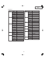
» Adjustment mode process menu
Adjustment mode process menu 1
* Adjust only the shaded items below.
First layer
DVD
Adjustment Process Menu
DTV
VERSION
DVD
SS
VIDEO
TEMP
AD
OPTION
DLP
PATTERN
VIDEO1
LAMP
PIXEL
LINE
Pedestal
EXIT
second layer
DTV
Contrast
Tint
Color
Sharpness
Bright
R-Bright
G-Bright
B-Bright
R-Contrast
G-Contrast
B-Contrast
EXIT
Initial Value
5
8
4
1
55
20
20
20
120
120
120
VIDEO
31
Contrast
Tint
Color
Sharpness
CTi-Level
LTi-Level
CB-Offset
CR-Offset
Bright
B-DRIVE
R-DRIVE
EXIT
Contrast
N-Tint
P-Tint
S-Tint
N-Color
P-Color
S-Color
Sharpness
CTi-Level
LTi-Level
CB-Offset
CR-Offset
Bright
B-DRIVE
R-DRIVE
EXIT
5
4
5
1
1
0
7
7
55
41
41
5
7
4
4
7
4
7
2
1
0
7
7
55
41
41
XV-Z2000
DT-400
Adjustment mode process menu 2
second layer
AD
R-Bright
G-Bright
B-Bright
R-Contrast
G-Contrast
B-Contrast
EXIT
DLP
Index Delay
R-Bright
G-Bright
B-Bright
R-Contrast
G-Contrast
B-Contrast
EXIT
VIDEO1
N-Contrast
P-Contrast
S-Contrast
Color
NT3.58Delay
NT4.43Delay
PAL Delay
SECAM Delay
Shapness2
EXIT
PIXEL
R-GAIN
G-GAIN
B-GAIN
EXIT
Pedestal R-Bright
G-Bright
B-Bright
R-Contrast
G-Contrast
B-Contrast
EXIT
Initial Value
40
40
40
120
120
120
325
128
128
128
100
100
100
14
14
15
17
0
1
5
0
1
128
128
128
-10
-10
-10
+10
+10
+10
second layer
VERSION Build
Boot Code
Config
RomCode
GUI
DLP
EXIT
SS
SS2
SS3 EU
SS4 US
SS5 JPN
SS6 CHIN
EXIT
TEMP
Temp1
Temp2
Temp3
Temp4
EXIT
OPTION PW365 Gamma
DLP Gamma
EXIT
PATTERN Cross Hatch
Color bar
EXIT
LAMP
Current Time
History1
History2
History3
History4
TOTAL TIME
EXIT
LINE
OFF
LED CHECK
EXIT
32
Initial Value
Parameter of sensor1
Parameter of sensor2
Standard VIDEO
8
Current time of use
One Earlier
Two Earlier
Three Earlier
Four Earlier
Total operating hours
XV-Z2000
DT-400
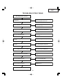
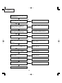
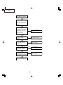
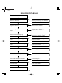
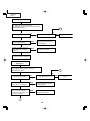
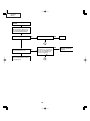
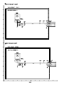
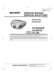
TROUBLESHOOTING TABLE
Checking the basic operation
Does the power LED light up or flash in
red or green?
NO
Go to "Checking the power supply system"
and "Checking the power unit".
NO
Go to "Checking the peripheral circuits of
the microprocessor".
YES
Does the set function with its keys or the
remote controller?
YES
Does the cooling fan rotate, and the lamp
turn on?
NO
Go to "Checking the lamp light-up".
YES
Is the user menu displayed?
NO
Go to "Checking the peripheral circuits of
the formatter".
NO
Go to "Checking the RGB input".
YES
Does the analog RGB input function
normally?
YES
Does the component input function
normally?
NO
Go to "Checking the component".
YES
Does the VIDEO input function normally?
NO
Go to "Checking of VIDEO input ".
YES
Does the DVI input function normally?
NO
Check the DVI circuit and its peripheral
circuits.
YES
Does the RS-232C function?
NO
Go to "Checking RS-232C".
YES
Does the autofocus function?
NO
Go to "Checking the IRIS, FOCUS and
ZOOM motors".
YES
End.
33
XV-Z2000
DT-400
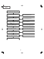
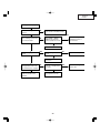
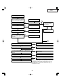
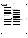
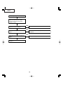
Checking the power supply system
Is 13V outputted to pins (9) and (11) of
P1707?
NO
Go to "Checking the power unit".
YES
Is 6V outputted to pins (1) and (3) of
P1707?
NO
Go to "Checking the power unit".
YES
Is the connector of P1707 fully inserted? NO
Is the voltage of 6V applied to both ends?
Replace the thermal fuse.
YES
NO
Check IC1707 and its peripheral circuits.
Is B+5VA outputted from IC1707?
YES
NO
Check IC1701 and its peripheral circuits.
Is Bu+5V outputted from IC1701?
YES
NO
Check IC1702 and its peripheral circuits.
Is Bu+3.3V outputted from IC1702?
YES
NO
Check IC1703 and its peripheral circuits.
Is Bu+2.5V outputted from IC1703?
YES
Go to "Checking the peripheral circuits of
the microprocessor".
34
XV-Z2000
DT-400
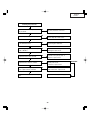
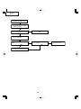
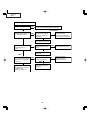
Checking the power unit
Is each connector of the power unit
fully inserted?
NO
Securely insert the connectors.
YES
Is the lamp door closed completely?
NO
Fix the lamp door with screws.
YES
Is the bimetal broken?
NO
Replace the bimetal switch or restore
by pressing the red button.
NO
Replace F701. If other parts are
damaged, replace them.
NO
Check D707 and the peripheral circuits
of IC702 on the primary side. If
defective, replace them.
NO
Replace the subunit or check the
primary side circuit.
if defective, replace them.
NO
Check the secondary-side circuits of
T701. If defective, replace them.
YES
Is AC voltage applied to both AC input
ends of DB701?
YES
Is DC voltage of approx. 6.25V
outputted to both ends of C726?
YES
Is DC voltage of approx. 370V
outputted to the cathode of D701?
YES
Is the specified voltage outputted to
each output terminal of EA701?
YES
Check the PWB circuits on each output
side.
Replace the ballast power supply.
35
ABNORMAL
XV-Z2000
DT-400
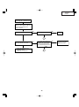
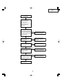
Checking the peripheral circuits of the
microprocessor
Are the voltages of approx. 3.3V and 2.5V
applied to both ends of C8001 and C8056
respectively?
NO
Go to "Checking the power supply
system".
YES
Are the oscillations of 133MHz and
74.25MHz outputted from pin (3) of
X8003 and pin (3) of X8007 respectively?
NO
Check X8001, X8003 and their peripheral
circuits.
YES
Does each terminal of R8038, R8039,
R8041, R8042 and R8050 change?
NO
Check IC8202 or IC8001 is defective.
YES
Do pins (15) and (16) of IC2002 change?
NO
Check IC8203 or IC2002 is defective. The
I2C bus does not function normally.
YES
Do pins (46) to (49) and (4) to (7) of
IC2002 change when any key is
operated?
NO
IC2002 is defective. The keys do not
function normally.
YES
When the power button is pressed, does
the voltage of pin (7) of IC8006 become
3.3V?
NO
IC8001 is defective.
YES
Do pulse-shaped waveforms appear at
pins (1), (2), (5) and (6) of IC8006?
NO
IC8006 is defective.
YES
Does the voltage of pins (3) and (6) of
IC8003 change?
NO
IC8003 is defective.
YES
Is the voltage of pin (2) of Q8002 5V?
NO
Q8002 is defective.
YES
Does the fan rotate?
Check the power supply circuit or fan
circuit on the main circuit.
NO
YES
Go to "Checking the lamp light-up".
36
XV-Z2000
DT-400
Checking the lamp light-up
Does each cooling fan
function?
NO
Check the power supply circuit
or fan circuit on the main circuit.
YES
Is the rotating sound of the
color wheel heard?
ABNORMAL
NO
YES
Go to "Checking the
peripheral circuits of
the formatter".
Check Q9401 to Q9403,
IC9401(motor driver IC)
and their peripheral circuits.
NORMAL
Replace the color wheel.
Is the discharging sound
heard?
YES
NO
Is the lamp tight in the
socket?
NO
Replace the lamp.
YES
Securely insert the
connectors.
Is DC voltage of approx.
NO
370V applied to both ends
of the ballast power supply?
YES
Go to "Checking the
peripheral circuits of the
formatter".
Is pin (2) of P1707 at the
"H" level?
NO
Check Q8002, Q8006 and
their peripheral circuits.
37
YES
Go to "Checking the
power unit".
XV-Z2000
DT-400
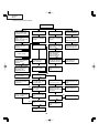
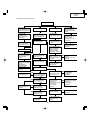
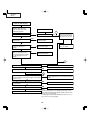
» Formatter Unit Troubleshooting
Display in trouble
Screen with spectral
colors
Color production of R,
G and B is not correct.
Black screen
Miscellaneous
Equally spaced white or
black vertical stripes
Black horizontal band
Adjustment by "Process
Menu" →"DLP" →
"INDEX". The failure state
remains unchanged.
Are the sockets SC2001
and SC9001 connected
correctly?
Are the socket SC2001
and SC9001 connected
correctly?
Are the contact terminals
of the DMD, formatter
PWB and cLGA dirty?
YES
YES
YES
Are the SC2001 and
SC9001 connected
correctly?
Does the color wheel
turn?
YES Does the pin (3) of
IC9201 have the correct
voltage +1.8V?
YES
NO
YES
Re-assemble the DMD,
the optical mechanism
and the formatter unit.
Are the signals fed to the
terminating resistance
(39W) of RDRAM
(IC9203)?(DQA8 and
DQB8 are unused.)
IC2002 is faulty.
YES
Do the colors return to
correct colors when the
process menu is
entered?
YES
NO
Does P9402 have the
correct motor drive
voltage waveform?
Is the waveform at pins NO
(18) and (20) of IC9202
the 400MHz sine wave?
YES
YES
Poor adjustment should
be a likely cause.
Perform readjustment
according to the
adjustment method.
IC9202, IC9101, X9101
or their peripheral
circuits are faulty.
IC9203, IC9101 or their
peripheral circuits are
faulty.
Color wheel is faulty.
NO
IC9401 or its peripheral
circuits are faulty.
Is the lamp lit on?
YES
NO
Check the color wheel
sensor unit.
Does pin (2) of P2004
have 150Hz pulse signal
in no-signal state?
Is pulse wave in voltage
at pin (14) of P1701?
YES
NO
NO
IC2001, IC2007 or their
peripheral circuits are
faulty.
YES
Is the correct voltage is
supplied to the each
connector of power and
ballast unit?
Does pin (9) of IC9301
have the correct voltage
(+23~+26V)?
YES
NO
Check the ballast unit
and the power unit.
YES
IC9301 or its peripheral
circuits are faulty.
NO
Does pin (13) of IC9301
have the correct voltage
(-26V)?
NO
Is the fan rotating?
YES
YES
NO
Does pin (49) of IC9301
have the correct voltage
(+7V)?
IC2007, IC2002 or their
peripheral circuits are
faulty.
YES
Double-check DMD and
cLGA units.
38
Check the fan circuit.
XV-Z2000
DT-400
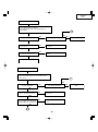
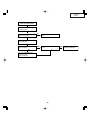
Checking the digital input
Input the digital signal from INPUT5.
Select digital with the keys on the main body or the
remote control.
1
YES
Is picture outputted?
YES
NO
Is the picture disturbed?
End.
NO
Is the signal coming to pins (10)(77) of IC502?
NO
Check between the input terminals
and IC502.
NO
Check IC8001 and its peripheral
circuits.
YES
Is the signal coming to pins (26)(54) and (66)-(94) of SC2001?
YES
Check the Formatter unit.
Checking the analog RGB input
Input the analog RGB signal from INPUT5.
Select INPUT5 with the keys on the main body or the
remote control.
1
YES
Is picture outputted?
YES
Is the picture disturbed?
NO
Is the picture signal coming to
pins (3), (4) and (5) of IC3102?
NO
Check between the input terminals
and IC3102.
NO
Check IC3102 and its peripheral
circuits.
YES
Are pins (76), (77) and (78) of
IC3102 outputting and the signals
inputted to pins (73), (74) and (75)?
YES
3
39
NO
End.
XV-Z2000
DT-400
Checking the Component
Send component signals to
INPUT1 or INPUT2. Use keys
on the main unit or remote
control to select INPUT1 or
INPUT2.
YES
Is video signal inputted into
pins (3) to (5) of IC3102 at the
time of INPUT1 selection, and
is inputted into pins (15) to
(17), respectively at the time of
INPUT2 selection?
NO
Check IC3102 and its
peripheral circuits.
NO
Check IC3102, IC3106 and
their peripheral circuits.
NO
Check IC3104 and its
peripheral circuits.
NO
Check IC6004 and its
peripheral circuits.
NO
Check IC8001 and its
peripheral circuits.
YES
Are video signals inputted to
pins (1), (3) and (5) of
IC3104?
YES
Are video signals inputted to
pins (43), (48) and (54) of
IC6004?
YES
Are video signals outputted
from pins (2)-(9), (12)-(19)
and (70)-(77) of IC6004?
YES
Is signal outputted to each
even number pin of pins (21)(54) and (66)-(94) of SC2001?
YES
Check Formatter unit again.
40
XV-Z2000
DT-400
Checking the Video Input
Feed the composite video signal to
INPUT 4. Select INPUT 4 using the
set's key or the remote controller.
End.
1
NO
Does the picture appear?
YES
YES
Is the picture disturbed?
NO
Is the video signal inputted to the
pin (1) of IC3105?
NO
Check the VIDEO-IN signal
line of Q3505.
YES
Check IC3504, IC3506 and
their peripheral circuits.
Is synchronized signal
coming to pins (28) and
(29) of IC3102?
YES
NO
YES
Are the video signals inputted to
pins (39) and (41) of IC3105?
Check IC3102 and its
peripheral circuits.
YES
Is the video signal outputted from
pins (21), (22) and (23) of IC3105
inputted to pins (67), (68) and (69)
of IC3102?
YES
YES
Check IC3501 and its
peripheral circuits.
3
Is there any input to pins (1), (3) and (5) of IC3104?
NO
Check IC3102 and its peripheral circuits.
YES
Is there any output from pins (16), (18) and (20) of IC3104?
NO
Check IC3104 and its peripheral circuits.
YES
2
Is the video signal inputted to pins (43), (48) and (54) of
IC6004 and the synchronized signal inputted to pins (30)
and (31)?
YES
NO
Is each digital output coming on pins (64), (65), (66) and
(67) of IC6004?
YES
NO
Is there any output from IC8001 (DPORT)?
YES
Check the formatter PWB.
Check IC3104, IC6001, IC6002 and their
peripheral circuits.
Check IC6004 and its peripheral circuits.
NO
Check IC8001 and its peripheral circuits.
Memo
The composite video signal is Y/C-separated by IC3506 (3 Line
COM) and the resulting signals are inputted to pins (39) and
(41) of IC3105.
The video signal is outputted from color-difference pins (21),
(22) and (23) of IC3105.
41
XV-Z2000
DT-400
Checking the SOG Circuit
Measure the pin (7) of IC5001
with an oscilloscope.
YES
Is the composite synchronized
signal regenerated at proper timing?
The SOG circuit is normal.
End.
NO
Measure the pin (2) of Q5001
with an oscilloscope.
Is there the Y signal including sync
signal?
NO
Is there any output from the pin
(25) of IC3102?
YES
YES
This is the failure of the SOG
synchronization separator circuit.
42
NO
Check Q3110 and its
peripheral circuits.
XV-Z2000
DT-400
Checking the S terminal input.
Input the S terminal (Y, C) signal to
INPUT 3. Select INPUT 3 with the
keys on the main body or the
remote controller.
Does the picture appear?
YES
Is the picture disturbed?
NO
NO
End.
YES
1
Is the video signal inputted to the
pins (43) and (44) of IC3105?
NO
YES
Is the video signal outputted
from pins (21), (22) and (23)
of IC3105 inputted into pins
(67), (68) and (69) of IC3102?
YES
Check the input side and its
peripheral circuits.
Check the Y,C signal line.
3
43
NO
Check IC3105 and its
peripheral circuits.
XV-Z2000
DT-400
Checking the Sync Signal
Is the horizontal synchronized
signal on pin (6) of IC6003?
NO
YES
Is the vertical synchronized signal
on pin (6) of IC6009?
NO
Check the of the signal input part.
YES
Is the synchronized signal
outputted from IC5009, IC5005,
IC5006, IC5007 and IC5008?
NO
Check each IC and their peripheral
circuits.
YES
Is the vertical synchronized signal
on pin (31) of IC6004?
NO
YES
Is the horizontal synchronized
signal on pin (30) of IC6004?
NO
Check IC6001, IC6002 and their
peripheral circuits.
YES
Is the vertical synchronized signal
on pin (64) of IC6004?
NO
YES
Is the horizontal synchronized
signal on pin (66) of IC6004?
NO
Failure of IC6004 and its
peripheral circuit.
YES
The sync signal is normal.
End of checking.
YES
Are the timing of both vertical and
horizontal synchronized signals
correct?
NO
Is the signal generator (input
source) correct?
NO
Set the signal source appropriately.
YES
2
IC8001 and its periphery is
defective.
44
XV-Z2000
DT-400
Checking RS-232C
Communication is disabled even though
connecting the control PC and projector
with a RS-232C cable.
Is the connecting cable connected
correctly? (cross cable)
NO
Replace the connecting cable.
YES
NO
Is there any signal at pin (8) of IC8002?
Check SC3501, R2039 and their peripheral circuits.
YES
NO
Is there any signal at pin (106) of IC2201?
Check IC2006 and its peripheral circuits.
YES
Check IC2002 and its peripheral circuits.
45
XV-Z2000
DT-400
Checking the IRIS, FOCUS and
ZOOM motors
Do all the motors function?
YES
Check the optical mechanism.
NO
Is 3.3V of IC8204 outputted as
specified?
NO
Check the B+6V input line, IC8204
and its peripheral circuits.
NO
Check pins (16) and (17) of
IC2002 and their peripheral
circuits.
YES
Is there I2C signal at pins (2) and
(3) of IC8201?
YES
YES
Are there remote control receiver
and key signals at pin (9) of
IC2002, pins (4) thru (7) as well as
(47) thru (49) of IC2002?
YES
Check IC2002 and its peripheral
circuits.
Is there any signal at the following
cases?
Zoom:Pin (3) and (7) of IC8205
Focus:Pin (11) and (15) of IC8205
Iris:Pin (2) and (4) of IC8206
NO
Check IC8201 and its peripheral
circuits.
NO
Check IC8205, IC8206 and their
peripheral circuits.
YES
Is there signal at pins (1) thru (4)
of P8201 and pins (1) and (2) of
P8202?
YES
Check the connection cable and
optical mechanism unit.
46
NO
Check the line up to the input
section and the remote control
receiver.
XV-Z2000
DT-400
TECHNISCHE DATEN
Produkttyp Projector
Modell XV-Z2000, DT-400
Videosystem PAL/PAL 60/PAL-M/PAL-N/SECAM/NTSC 3.58/NTSC 4.43
DTV 480I/480P/540P/576I/576P/720P/1080I
Display-Verfahren Einzel-Bedienungsfeld-Digital Micromirror Device (DMDTM) von Texas Instruments
DLP-Feld Feldformat: 0,8"
Ansteuerungsmethode: Digital Light Processing (DLPTM)
Anzahl der Punkte: 921.600 Punkte (1.280[H] ⋅ 720 [V])
Linse 1 –1,5 X Zoom-Linse, F2,0 –2,5, f=21,3 –31,6 mm
Projektionslampe Gleichstromlampe 275 W
Videoeingangssignal RCA-Stecker: VIDEO (INPUT 4), Gemischtes Video, 1,0 Vp-p, Synch. negativ, 75 Ω
terminiert
S-Videoeingangssignal 4-Pin Mini DIN-Stecker (INPUT 3)
Y (Luminanz-Signal): 1,0 Vp-p, Synch. negativ, 75 Ω terminiert
C (Chrominanz-Signal): Stoß 0,286 Vp-p, 75 Ω terminiert
Komponenten-Eingangssignal RCA-Stecker
(INPUT 1, 2) Y: 1,0 Vp-p, Synch. negativ, 75 Ω terminiert
PB (CB): 0,7 Vp-p, 75 Ω terminiert
PR (CR): 0,7 Vp-p, 75 Ω terminiert
Analog-RGB/Digital 29-Pin DVI-I-Terminal
(INPUT 5/DIGITAL) <Digital>
Eingangsimpedanz 50 Ω
Eingangspegel 250-1000 mV
<Analog>
Eingangsimpedanz 75 Ω
Eingangspegel 0,7 Vp-p
Y: 1,0 Vp-p, Synch. negativ, 75 Ω terminiert
PB (CB): 0,7 Vp-p, 75 Ω terminiert
PR (CR): 0,7 Vp-p, 75 Ω terminiert
<Synchronisationssignal>
•Separates Synch./Komposit-Synch.
Eingangspegel TTL-Pegel
Eingangsimpedanz 1 KΩ
•Grün auf Synch.
Eingangspegel (Synchronisierungseingang) 0,286Vp-p
Eingangsimpedanz 75 Ω
Horizontal-Auflösung 720 TV-Zeilen (DTV 720P)
Punktetakt 12–80 MHz
Vertikale Frequenz 43–75 Hz
Horizontale Frequenz 15–70 kHz
Computersteuerungs-Signal 9-Pin D-Sub-Steckanschluß (RS-232C-Eingangs-Port)
Nennspannung 100–240 V Wechselstrom (Hongkong: 220 V)
Eingangsspannung 3,65 A(Bei 100 V Wechselstrom)/(Hongkong: 1,6 A)
Nennfrequenz 50/60 Hz(Hongkong: 50 Hz)
Stromaufnahme 360 W(Bei 100 V Wechselstrom)/(Hongkong: 345W)
Stromaufnahme(Bereitschaft) 6W(Bei 100 V Wechselstrom)
Wärmeabgabe 1.350 BTU/Stunde
Betriebstemperatur +5°C bis +35°C
Lagertemperatur –20°C bis +60°C
Gehäuse Kunststoff
I/R-Trägerfrequenz 38 kHz
Abmessungen (ca.) 310× 89 × 282 mm (B × H × T)
Gewicht (ca.) 4,3 kg
Mitgeliefertes Zubehör Fernbedienung, Zwei AA-Batterien, Netzkabel, 21-Pin RCA- Konvertierungsadapter,
Video-Kabel, Linsenkappe (am Gehäuse befestigt), Bedienungsanleitung
Ersatzteile Lampeneinheit (Lampe/Gehäusemodul) (AN-K2LP), Fernbedienung (RRMCGA334WJSA),
AA-Batterien, Netzkabel (QACCDA007WJPZ:XV-Z2000 für USA, Kanada und DT-400) (für
Europa, ausgenommen Großbritannien) (QACCVA011WJPZ:XV-Z2000 für Europa,
ausgenommen Großbritannien) (QACCBA036WJPZ:XV-Z2000 für Großbritannien,Hongkong
und Singapur) (QACCLA018WJPZ:XV-Z2000 für Australien und Neuseeland)21-Pin RCAKonvertierungsadapte (QSOCZ0361CEZZ:XV-Z2000 für Europe), Video-Kabel
(QCNWGA001WJZZ:Ausgenommen XV-Z2000 für USA, Kanada und DT-400), Linsenkappe
(PCAPHA021WJSA), Bedienungsanleitungen (TINS-B529WJZZ:XV-Z2000 für USA und Kanada)
(TINS-B530WJZZ:XV-Z2000 für 7 europäische Sprachen) (TINS-B531WJZZ:XV-Z2000 für
Hongkong und Koreanisch) (TINS-B532WJZZ:DT-400)
Bedingt durch fortlaufende technische Verbesserungen behält sich SHARP das Recht
vor, das Design und die Spezifikationen ohne vorherige Ankündigung ändern zu können.
Die angegebenen Leistungswerte stellen die Nennwerte einer in Serienherstellung
produzierten Einheit dar. Geringe Abweichungen bei einzelnen Geräten sind möglich.
47
XV-Z2000
DT-400
HINWEISE FÜR DAS
WARTUNGSPERSONAL
123456789012345678901234567890121234567890123456
123456789012345678901234567890121234567890123456
ACHTUNG: UV-STRAHLUNG
123456789012345678901234567890121234567890123456
123456789012345678901234567890121234567890123456
Die Beleuchtungsquelle des LCD-Projektors, eine
UHP-Lampe, emittiert eine geringe Menge
UV-Strahlung.
DIREKTE BESTRAHLUNG AUF AUGEN
UND HAUT MUSS VERMIEDEN WERDEN.
Zur Gewährleistung der Sicherheit muß folgendes
beachtet werden:
Auswechseln der Lampe
Hinweis:
Da die Lampe während des Betriebs sehr heiß wird, sollte
die Lampe erst ausgewechselt werden, nachdem das
Gerät mindestens eine Stunde ausgeschaltet war, damit
die Lampe ausreichend abkühlen kann.
Beim Installieren der neuen Lampe muß darauf
geachtet werden, die Lampe selbst (Glaskolben)
nicht zu berühren. Vielmehr muß die Lampe am
Reflektor 2 gehalten werden.
[Es darf nur ein Original-Ersatzteil verwendet
werden.]
1 Lampe
1. Bei Arbeiten am Projektor bei eingeschalteter
Lampe und abgenommenem oberen Gehäuse muß
unbedingt eine Sonnenbrille getragen werden.
2 Reflektor
GEFAHR! — Niemals die Spannungsversorgung
einschalten, ohne daß eine Lampe vorhanden ist, um
elektrische Schläge und Schäden am Gerät zu
vermeiden, da der Stabilisator anfangs hohe
Spannungen erzeugt.
2. Die Lampe darf nicht außerhalb des
Lampengehäuses eingeschaltet werden.
Da eine geringe Menge UV-Strahlung an der Öffnung
zwischen den Lüftern austritt, wird empfohlen, während
der Wartungsarbeiten die Abdeckkappe des Zusatzobjektivs an dieser Öffnung anzubringen, um Augen
und Haut vor den UV-Strahlen zu schützen.
3. Betrieb für länger als 2 Stunden bei
abgenommenem Gehäuse ist nicht zulässig.
Zur Beachtung bei UV-Strahlung
und Mitteldruck-Lampen
1. Vor dem Auswechseln der Lampe muß der Netzstecker
gezogen werden.
2. Vor Durchführung von Wartungsarbeiten muß das
Gerät eine Stunde abkühlen.
3. Die Lampe darf nur gegen eine der gleichen Art
ausgewechselt werden. Typ AN-K2LP bemessen für
275W.
4. Die Lampe gibt eine geringe UV-Strahlung ab, daher
muß direkter Augenkontakt vermieden werden.
5. Die Mitteldruck-Lampe weist ein Explosionsrisiko auf.
Daher müssen die nachstehenden
Installationsanweisungen beachtet werden, und die
Lampe muß vorsichtig behandelt werden.
48
XV-Z2000
DT-400
Vorsichtsmaßregeln für bleifreien Lötzinn
1 Verwendung von bleifreiem Lötzinn
Bei den Platinen für dieses Modells wird bleifreies Lot verwendet. Das Symbol LF kennzeichnet bleifreies Lot und
findet sich an den Platinen und in den Wartungshandbüchern. Der Buchstabe hinter LF bezieht sich auf die Art des
bleifreien Lots.
Beispiel:
LFa
Zeigt bleifreien Lötzinn aus Zinn, Silber und Kupfer an.
2 Bei Reparatur der mit bleifreiem Lötzinn gelöteten Platine immer bleifreien Lötzinn verwenden. Reparatur mit
herkömmlichem Lötzinn kann zu Schäden oder Unfällen aufgrund von Rissen führen.
Da der Schmelzpunkt bleifreien Lvtzinns (Sn-Ag-Cu) um 40°C höher als der von Bleidraht-Lötzinn ist, empfehlen
wir die Verwendung einer speziellen Lötspitze. Wenn Fragen über den Beschaffung leitfreien Lötzinns oder spezieller
Lötspitzen bestehen, wenden Sie sich an unsere Kundendienstvertretung in Ihrem Gebiet.
3 Löten
Da der Schmelzpunkt bleifreien Lötzinns (Sn-Ag-Cu) etwa 220°C beträgt, was um 40°C höher als der von bleihaltigem
Lötzinn ist, und außerdem schlechte Löt-Benetzbarkeit aufweist, kann es erforderlich werden, die Lötspitze längere
Zeit in Kontakt mit der Platine zu halten. Da die Lötlauge abfliessen kann oder der maximale Hitzewiderstand von
Teilen überschritten werden kann, die Lötspitze sofort von der Platine nehmen, sobald eine gute Lötung erzielt ist.
Bleifreier Lötzinn enth_lt mehr Zinn, und das Ende der Lötspitze kann leicht angegriffen werden. Immer sicherstellen,
dass der Lötkolben nur bei Bedarf eingeschaltet wird.
Wenn ein anderer Typ von Lötzinn an der Lötspitze haften bleibt, verschmilzt er mit dem bleifreien Lötzinn. Die
Lötspitze nach jeder Verwendung reinigen.
Wenn die Lötspitze bei der Verwendung geschwärzt wird, die Spitze mit Stahlwolle oder feinem Sandpapier
abschmirgeln.
Immer beim Austausch von Teilen vorsichtig sein, und die Polaritätsanzeige auf der Platinenbeschriftung beachten.
Bleifreier Lötzinn zur Wartung
Teile-Nr.
ZHNDAi123250E
ZHNDAi126500E
ZHNDAi12801KE
★
J
J
J
Beschreibung
φ0.3mm
250g(1roll)
φ0.6mm
500g(1roll)
φ1.0mm
1 Rolle
49
Code
BL
BK
BM
XV-Z2000
DT-400
BEDIENUNGSANLEITUNG
Projektor
Draufsicht
ON-Taste
Schaltet die Stromversorgung ein.
Netz-Anzeige
STANDBY-Taste
Lampen-Anzeige
Schaltet den Projektor in den
Standby-Modus.
TemperaturwarnAnzeige
RESIZE-Taste
Für das Umschalten der Bildanzeige
(STRECKEN, SEITENBALKEN, usw.).
ZOOM/FOCUS-Taste
Für das Einstellen der
projizierten Bildgröße oder
das Einstellen des Fokus.
ENTER-Taste
Für das Einstellen der
ausgewählten oder eingestellten
Menüpunkte.
UNDO-Taste
Für das Rückgängigmachen eines
Bedienschrittes oder für die Rückkehr
zur vorherigen Anzeige.
INPUT-Taste
Wählen Sie zwischen den
Eingangsmodi 1, 2, 3, 4, 5
oder DIGITAL
MENU-Taste
Für die Anzeige des Justierungsund Einstellungsbildschirms.
Einstelltasten
('/"/\/|)
Für das Auswählen von
Menüpunkten und anderen
Einstellungen.
Vorderansicht
Fernbedienungssensor
Vorderer Einstellfuß
(auf der Unterseite des
Projektors)
HEIGHT ADJUST-Taste
• Anbringen der Objektivkappe
Drücken Sie die Objektivkappe
auf, bis diese in Position einrastet.
• Abnehmen der Objektivkappe
Ziehen Sie die Objektivkappe
nach außen.
50
XV-Z2000
DT-400
Informationen über die Anzeigen des Projektors
Netz-Anzeige
Rot leuchtend ... Normal (Standby)
Grün leuchtend ... Normal (Eingeschaltet)
Lampen-Anzeige
Grün leuchtend ... Normal
Grün blinkend ... Die Lampe wird aufgewärmt oder wird
ausgeschaltet.
Rot leuchtend ... Die Lampe wurde auf unnormale
Weise ausgeschaltet oder muss
ausgewechselt werden.
Temperaturwarn-Anzeige
Aus ... Normal
Rot leuchtend ... Die Temperatur im Inneren des
Gerätes ist zu hoch.
51
XV-Z2000
DT-400
Projektor (Rückansicht)
Anschlüsse Beachten Sie die Erläuterungen unter „INPUT (EINGANG)-Anschlüsse und
Hauptausrüstung zum Anschließen“ .
INPUT 2-Anschluss
Anschluss für
Komponentensignale.
INPUT 4-Anschluss
Anschluss für ein
Videogerät.
INPUT 1-Anschluss
Anschluss für
Komponentensignale.
INPUT 3-Anschluss
Anschluss für ein Videogerät
mit einem
S-Video-Anschluss.
Digitaler EingangstypSchalter
INPUT 5/DIGITALAnschluss
RS-232C-Anschluss
Anschluss für die Bedienung des
Projektors unter Verwendung eines
Computers.
Luftaustrittöffnung
Die Geschwindigkeit und das
Geräusch des Kühlventilators kann
sich abhängig von internen
Temperaturschwankungen während
des Betriebes verändern. Dies ist
ein normaler Vorgang und kein
Zeichen für eine Fehlfunktion.
Einsaugöffnung
Fernbedienungssensor
Kensington-Sicherheitsstandardanschlus
Hinterer Einstellfuß
Netzanschluss
Schließen Sie das
mitgelieferte Netzkabel an.
Verwendung der Kensington-Sperre
• Dieser Projektor ist mit einem Kensington-Sicher-heitsstandardanschluss für die Verwendung des Kensington
MicroSaver-Sicherheits-systems ausgestattet. Lesen Sie hinsichtlich dessen Verwen-dung die Informationen,
die dem System beiliegen, um den Projektor zu sichern.
52
XV-Z2000
DT-400
Fernbedienung
STANDBY-Taste
Schaltet den Projektor in den
Standby-Modus.
ON-Taste
Schaltet die Stromversorgung ein.
KEYSTONE-Taste
Für das Aktivieren des TrapezverzerrungsKorrekturmodus.
MENU-Taste
Für die Anzeige des Justierungs- und
Einstellungsbildschirms.
ENTER-Taste
Einstelltasten
('/"/\/|)
Für das Einstellen der ausgewählten
oder eingestellten Menüpunkte.
UNDO-Taste
Für das Rückgängigmachen eines Bedienschrittes
oder für die Rückkehr zur vorherigen Anzeige.
ZOOM/FOCUS-Taste
Für das Einstellen der
projizierten Bildgröße oder
das Einstellen des Fokus.
INPUT 1-Taste
INPUT 2-Taste
INPUT 3-Taste
DIGITAL INPUT-Taste
INPUT 4-Taste
INPUT 5-Taste
AUTO SYNC-Taste
Für das automatische Einstellen von Bildern,
wenn ein Computer angeschlossen ist.
RESIZE-Taste
Für das Umschalten der Bildanzeige
(STRECKEN, SEITENBALKEN, usw).
RGB/COMP.-Taste
Zum Umschalten des Signaltyps
(RGB oder Komponente).
PICTURE MODE-Taste
Wählen Sie die Bildeinstellung
(Speicher) aus, die in “Bildmodus” im
“Bild”-Menü gespeichert ist.
IRIS-Taste
Zum Umschalten zwischen „HOHE
HELLIGKEITS-MODUS“ und
„HOHER KONTRAST-MODUS“.
Hinweis
• Alle Tasten der Fernbedienung bestehen aus fluoreszierendem Gummi, das im Dunkeln leuchtet. Der
Leuchteffekt lässt mit der Zeit nach. Die selbstleuchtenden Tasten werden wieder aufgeladen, wenn Sie
Licht ausgesetzt werden.
53
XV-Z2000
DT-400
Fernbedienungssensor
Vorderansicht
30°
Reichweite
30°
Der Projektor kann mittels der Fernbedienung
innerhalb der in der Abbildung dargestellten
Bereiche gesteuert werden.
Signalsender für
Fernbedienung
7m
30°
Hinweis
• Das Signal von der Fernbedienung kann für eine
einfache Bedienung von der Bildwand reflektiert
werden. Die tatsächliche Reichweite des Signals
kann je nach Bildwandmaterial unterschiedlich sein.
Fernbedienung
Rückansicht
Bei Verwendung der Fernbedienung:
Fernbedienungssensor
• Nicht fallen lassen, keiner Feuchtigkeit oder hohen
Temperatur aussetzen.
• Die Fernbedienung funktioniert unter Umständen
nicht unter einer Fluoreszenzlampe. Unter diesen
Umständen den Projektor von der Fluoreszenzlampe
entfernt aufstellen.
30°
30°
7m
30°
Signalsender für
Fernbedienung
Einlegen der Batterien
Fernbedienung
1
Ziehen Sie die Lasche an der
Abdeckung herunter und entfernen
Sie die Abdeckung in Pfeilrichtung.
2
Die beiliegenden Batterien(zwei
Batterien der Größe “AA”) einlegen.
• Die Batterien einlegen und sicherstellen,
und
dass die Pole mit der Markierung
im Batteriefach übereinstimmen.
3
Führen Sie die untere Lasche
der Abdeckung in die Öffnung
ein und senken Sie die
Abdeckung bis sie einrastet.
Falsche Verwendung der Batterien kann eine Leckage oder Explosion zur Folge haben. Bitte befolgen
Sie die unten stehenden Vorsichtsmaßnahmen.
Achtung
• Die Batterien einlegen und sicherstellen, dass die Pole mit den Markierungen
und
im Batteriefach übereinstimmen.
• Batterien unterschiedlichen Typs haben unterschiedliche Eigenschaften, verwenden Sie deshalb keine Batterien
unterschiedlichen Typs zusammen.
• Verwenden Sie keine neuen und alten Batterien zusammen.
Dadurch könnte die Lebensdauer der neuen Batterien reduziert oder ein Auslaufen der Batterien verursacht werden.
• Nehmen Sie leere Batterien aus der Fernbedienung heraus, da sie ansonsten auslaufen könnten.
Aus den Batterien ausgelaufene Batterieflüssigkeit ist für Ihre Haut schädlich, wischen Sie die Batterien deshalb unbedingt
zuerst ab und nehmen Sie sie dann mit einem Tuch heraus.
• Die diesem Projektor beiliegenden Batterien können unter Umständen, je nach Handhabung, nach kurzer Zeit
aufgebraucht sein. Stellen Sie sicher, dass sie so bald wie möglich durch neue Batterien ersetzt werden.
54
XV-Z2000
DT-400
Verbindungs-Pin-Zuweisungen
DVI-I (INPUT 5)-Anschluss: 29-pol. Stecker
• DVI-Digital-Eingang
9
~
16
∞ ∞ ∞ ∞ ∞ ∞ ∞ ∞ ∞∞ ∞ ∞ ∞ ∞ ∞ ∞ ∞ ∞
1 2
~ ∞∞∞∞ 7 8
∞∞∞∞
C1
C2
C4
C5
C3
17
24
18
~ ∞ ∞ ∞ ∞ 23
∞∞∞∞
Pin Nr. Signal
1 T.M.D.S.-Daten 22 T.M.D.S.-Daten 2+
3 T.M.D.S.-Daten 2-Schutz
4 Nicht angeschlossen
5 Nicht angeschlossen
6 DDC-Takt
7 DDC-Daten
8 Nicht angeschlossen
9 T.M.D.S.-Daten 110 T.M.D.S.-Daten 1+
11 T.M.D.S.-Daten 1-Schutz
12 Nicht angeschlossen
13 Nicht angeschlossen
14 Stromversorgung + 5 V
15 Erde
• DVI-Analog-RGB-Eingang
Pin Nr.
1
2
3
4
5
6
7
8
9
10
11
12
13
14
15
Signal
Pin Nr.
Nicht angeschlossen
16
Nicht angeschlossen
17
Nicht angeschlossen
18
Nicht angeschlossen
19
Nicht angeschlossen
20
DDC-Takt
21
DDC-Daten
22
Vertikales Synch.
23
Nicht angeschlossen
24
Nicht angeschlossen
C1
Nicht angeschlossen
C2
Nicht angeschlossen
C3
Nicht angeschlossen
C4
Stromversorgung + 5 V C5
Erde
Pin Nr.
16
17
18
19
20
21
22
23
24
C1
C2
C3
C4
C5
Signal
Zündkerzenerkennung
T.M.D.S.-Daten 0T.M.D.S.-Daten 0+
T.M.D.S.-Daten 0-Schutz
Nicht angeschlossen
Nicht angeschlossen
T.M.D.S.-Taktschutz
T.M.D.S.-Takt+
T.M.D.S.-TaktNicht angeschlossen
Nicht angeschlossen
Nicht angeschlossen
Nicht angeschlossen
Erde
• DVI-Analog-Komponenten-Eingang
Signal
Zündkerzenerkennung
Nicht angeschlossen
Nicht angeschlossen
Nicht angeschlossen
Nicht angeschlossen
Nicht angeschlossen
Nicht angeschlossen
Nicht angeschlossen
Nicht angeschlossen
Analog-Eingang Rot
Analog-Eingang Grün
Analog-Eingang Blau
Horizontales Synch.
Erde
Pin Nr.
1
2
3
4
5
6
7
8
9
10
11
12
13
14
15
Signal
Pin Nr.
Nicht angeschlossen
16
Nicht angeschlossen
17
Nicht angeschlossen
18
Nicht angeschlossen
19
Nicht angeschlossen
20
Nicht angeschlossen
21
Nicht angeschlossen
22
Nicht angeschlossen
23
Nicht angeschlossen
24
Nicht angeschlossen
C1
Nicht angeschlossen
C2
Nicht angeschlossen
C3
Nicht angeschlossen
C4
Nicht angeschlossen
C5
Erde
Signal
Nicht angeschlossen
Nicht angeschlossen
Nicht angeschlossen
Nicht angeschlossen
Nicht angeschlossen
Nicht angeschlossen
Nicht angeschlossen
Nicht angeschlossen
Nicht angeschlossen
Analog-Eingang PR/CR
Analog-Eingang Y
Analog-Eingang PB/CB
Nicht angeschlossen
Erde
RS-232C-Port: 9-Pin D-Sub-Stecker
9 8 76
54 321
Pin Nr.
1
2
3
4
5
6
7
8
9
Signal
RD
SD
SG
Name
E/A
Daten empfangen Eingang
Daten senden
Ausgang
Reserviert
Signalerdung
Reserviert
Reserviert
Reserviert
55
Referenz
Nicht angeschlossen
An internen Schaltkreis angeschlossen
An internen Schaltkreis angeschlossen
An internen Schaltkreis angeschlossen
An internen Schaltkreis angeschlossen
An internen Schaltkreis angeschlossen
An internen Schaltkreis angeschlossen
An internen Schaltkreis angeschlossen
Nicht angeschlossen
XV-Z2000
DT-400
ABMESSUNGEN
Einheiten: mm
Ansicht
von hinten
Ansicht von
der Seite
1,5
Ansicht von
oben
3,25
282
Ansicht von
der Seite
310
5
55,5
89
Ansicht von
vorne
48,5
55,05
99,95
129,5
129,5
29,1 30,9
M4
M4
M4
44,1 30,9
56
106,3
14
15,5
M4
225,3
210,3
Ansicht von
unten
XV-Z2000
DT-400
ENTFERNEN DER HAUPTTEILE
1. Ausbau der Lampentür und der Lampeneinheit
1-1. Die Lampentür-Befestigungsschraube herausdrehen, dann die Lampentür abnehmen.
1-2. Die 2 Lampeneinheits-Befestigungsschrauben herausdrehen, dann die Lampeneinheit abheben.
Lampeneinheit
1-3
Lampentür
1-2
2. Ausbau des oberen Gehäuses
2-1. Eine Postkarte oder ein dickes papier unter dem objektivtubus einzuführen.
2-2. Die 6 Befestigungsschrauben für das obere und das untere Gehäuse herausdrehen.
2-3. Die mit * bezeichneten Teile gedrückt halten und die Klauen am oberen Gehäuse freigeben, um das obere
Gehäuse abzunehmen.
Oberes Gehäuse
2-4. Die Postkarte wieder herausziehen.
Um den Objektivtubus gegen
Kratzer zu schützen
2-3
2-2
Unteres Gehäuse
2-1
2-2
2-4
Kurze Seite
(10cm)
Lange Seite
(15cm)
Dickes papier wie
eine Postkarte
57
XV-Z2000
DT-400
3. Anbringen der oberen Gehäuses (Für die geeigneten Schrauben ist auf den
Abschnitt "2. Aubau des oberen Gehäuses" Bezug zu nehmen.)
3-1. Die Postkarte über dem Objektivtubus einführen.
3-2. Die obere Gehäuse aufsetzen. Sicherstellen, daß die vier Haken gut einrasten.
3-3. Die Postkarte wieder herausziehen.
Oberes Gehäuse
3-2
Unteres Gehäuse
3-1
3-3
Dickes Papier wie z.B.
eine Postkarte
4. Ausbau der Hauptleiterplatteneinheit und der peripheren Einheiten
4-1.
4-2.
4-3.
4-4.
4-5.
4-6.
4-7.
Die 4 Hauptleiterplatten-Befestigungsschrauben (Klemmenseite) herausdrehen.
Die 9 Hauptleiterplatten-Befestigungsschrauben herausdrehen.
Die 12 Anschlüsse aus der Hauptleiterplatte entfernen.
Den Anschluss an der Schalterhalterung herausziehen, dann die 3 Befestigungsschrauben herausdrehen.
Die Befestigungsschrauben für die vordere R/C-Leiterplatte herausdrehen.
Die 2 Befestigungsschrauben für die knopf-Halter herausdrehen.
Die Hauptleiterplatte in querer Richtung von der Optische Laufwerkeinheitseite abheben.
4-3
Hauptleiterplatten
4-2
4-4
Schalterhalterung
4-5
4-7
Voedere R/C einheit
4-1
4-6
Knopf-Halter
58
XV-Z2000
DT-400
5. Ausbau der optischen Laufwerkeinheit
5-1.
5-2.
5-3.
5-4.
5-5.
Die Befestigungsschrauben für die Halterung.
Die zwei Sperrschrauben vom Lampenfassung entfernen.
Die 5 Befestigungsschrauben für die optische Laufwerkeinheit herausdrehen.
Den Kanal abnehmen.
Die Lautsprecherhalter abnehmen.
5-2
Kanal
5-4
5-3
Optische Laufwerkeinheit
5-1
Halterung
Lampenfassung
5-5
Lautsprecherhalter
5-3
6. Ausbau der Vorschaltgerät/Netz-Einheit
6-1. Die 3 Befestigungsschrauben für die Vorschaltgerät/Netz-Einheit herausdrehen.
6-1
Vorschaltgerät/Netz-Einheit
6-1
59
XV-Z2000
DT-400
7. Ausbau der Vorschaltgerät/Netz-Einheit
7-1.
7-2.
7-3.
7-4.
Die Befestigungsschraube für die hintere R/C-einheit herausdrehen.
Die 4 Befestigungsschrauben, 4 WH-Naben und den Randhalter für die Vorschaltgerätteil entfernen.
Die 11 Befestigungsschrauben und 5 WH-Naben für das Netzteil entfernen.
Die 4 Befestigungsschrauben für das Gebläse herausdrehen.
7-3
Netzeinheit
7-1
7-3
Hintere-R/C-einheit
7-4
7-3
Netzteil
Luftfluß
7-2
7-3
Gebläse
Vorshaltgerat-einheit
7-2
7-3
Randhalter
7-3
Voeschaltgerätteil
7-2
8. Ausbau der peripheren Einheiten
8-1. Die 4 Befestigungsschrauben für die Vorder Einstellfuß herausdrehen.
8-2. Die 8 Befestigungsschrauben herausdrehen, dann die Halterungen A und B sowie die Erdplatte abnehmen.
8-2
Halterungen-A
Halterungen-B
8-1
Vorder Einstellfuß Halter
Height Adjust-Taste
Vorder Einstellfuß
60
XV-Z2000
DT-400
9. Befestigen der Erdungsplatte
9-1.
9-2.
9-3.
9-4.
9-5.
9-6.
9-7.
9-8.
Die vier Muttern anbringen.
Die Verstärkung (Halterung A) aufsetzen.
Die Erdungsplatte wie gezeigt ansetzen.
Die Verstärkung (Halterung B) aufsetzen.
Die vier M3-Schrauben festziehen.
Die vier M4-Schrauben festziehen.
Die Erdungsplatte wie gezeigt ansetzen.
Die sechs 17 der Erdungsplatte schmelzen.
9-6 M4-Schrauben
9-5 M3-Schrauben (4 Stellen)
(4 Stellen)
9-4 Verstärkung
(Halterung B)
9-3 Erdungsplatte
9-1 Verstärkung
(Halterung A)
9-2 Muttem (4 Stellen)
9-7 Erdungs platte
9-8 Die 17 Stifte schmelzen.
Vorsichtsmaßnahme:
*Die Stifte mit eniem Lötkolben
schmelzen, um die
Erdungsplatte zu befestigen.
Zum Schluß auf Lockerheit
überprüfen.
61
XV-Z2000
DT-400
RÜCKSTELLUNG DES LAMPEN-TIMERS
● Rückstellung des Lampen-Timers
Den Lampen-Timer nach dem Lampenaustausch zurückzustellen.
Info
• Stellen Sie sicher, dass Sie den Lampen-Timer
nur nach dem Austausch der Lampe zurücksetzen.
Wenn Sie den Lampen-Timer zurückstellen und
dieselbe Lampe weiterhin verwenden, könnte die
Lampe beschädigt werden oder explodieren.
1
2
Netzanschluss
ON-Taste
Das Netzkabel anschließen.
ENTER-Taste
• Das Netzkabel am Netzanschluss des
Projektors anschließen.
\/| Tasten
UNDO-Taste
Den Lampen-Timer zurückstellen.
• Drücken Sie auf dem Projektor in folgender
Reihenfolge die Tasten
,
,
,\,
| drücken Sie anschließend die Tste
INPUT-Taste
und
.
• „LAMP 0000H“ wird im unteren linken Teil des
Bildschirms angezeigt und weist darauf hin,
dass der Lampen-Timer zurückgesetzt wurde.
Lampe
■ Es wird empfohlen, die Lampe (separat erhältlich) auszutauschen, wenn die Lampenlebensdauer 5 % oder weniger
beträgt, oder wenn Sie eine deutliche Verschlechterung der Bild- und Farbqualität feststellen. Die
Lampenlebensdauer (Prozentsatz) kann auf der Bildschirmanzeige überprüft werden.
■ Erwerben Sie über einen Sharp-Projektor-Händler oder Kundendienstbetrieb in Ihrer Nähe eine Lampe des Typs
AN-K2LP.
■ Die Warnanzeigen (ON/STANDBY-Taste, Lampen-Anzeige und Temperatur-Warnanzeige) auf dem Projektor weisen
auf Funktionsstörungen hin.
■ Wenn eine Funktionsstörung auftritt, beginnt die Temperatur-Warnanzeige oder die Lampen- Anzeige zu leuchten,
und der Projektor wechselt in den Standby-Modus. Fürhren Sie die folgenden Schritte aus, nachdem der Projektor
in den Standby-Modus gewechselt ist.
Wartungsanzeigen
Netz-Anzeige
Lampen-Anzeige
Temperaturwarn-Anzeige
Über die Temperaturwarn-Anzeige
Wenn der Monitor sich infolge nicht ordnungsgemäßer Aufstellung oder blockierter Belüftungsöffnungen
überhitzt, leuchtet am unteren linken Rand des Bildes „
“ auf. Wenn die Temperatur weiterhin steigt,
wird die Lampe ausgeschaltet. Die Temperaturwarn-Anzeige auf dem Projektor beginnt zu blinken. Nachdem
der Lüfter weiterläuft, schaltet sich der Projektor in den Standby-Modus. Nachdem „
“ erscheint,
führen Sie auf jeden Fall die Maßnahmen aus wie beschrieben.
62
XV-Z2000
DT-400
63
XV-Z2000
DT-400
BESCHREIBUNG DER OPTIK-EINHEIT
Erläuterungen für das korrekte Setup der optischen Komponenten und Baugruppen (Ansicht von oben)
(Schematische Darstellung)
Reflektorspiegel
Projektionslinse
Farbrad
Lampe
Feldlinse
DMD
Stab
UV-Filter
Beleuchtungslinsen 1
Beleuchtungslinsen 2
Objekt
Lampe
Farbrad
Stab
Beleuchtungslinsen
Reflektorspiegel
Feldlinse
DMD
Projektionslinse
Funktion
Lichtquelle. Gleichstrom-Hochdruck-Quecksilberlampe
Teilt durch den Farbfilter das Licht aus der Lichtquelle in R, G, B und W auf.
Entwickelt einen gleichmäßigen Lichtstrahl.
Fokussieren das Licht aus dem Stab auf DMD.
Reflektiert das Licht aus den Beleuchtungslinsen gegen DMD.
Fokussiert das Licht aus dem Reflektorspiegel auf DMD und das Licht aus DMD
auf Projektionslinse.
Schaltet im Verhältnis von Farbkomponente jedes Bildpunktes der Eingangsquelle
den internen Mikrospiegel ein/aus, um das Licht zu reflektieren.
Vergrößert das Licht aus DMD und projiziert es auf eine Leinwand.
64
XV-Z2000
DT-400
Luftfluß
Wenn nach dem Austausch von DMD eine Abschattung auf der Leinwand erscheint (siehe Abbildung 1), den
Beleuchtungsbereich von DMD einstellen, indem man die Einstellschrauben für den optischen Motor dreht.
1. Die Befestigungsschraube für den Einstellhebel 1 lösen. Den Beleuchtungsbereich mit dem Einstellhebel 2
einstellen, dann die Befestigungsschraube für den Einstellhebel 1 anziehen.
2. Wenn der Beleuchtungsbereich nach dem obigen Verfahren nicht eingestellt werden kann, die Befestigungsschraube
3 lösen, und den Bereich mit den Einstellschrauben 4 und 5 einstellen; danach die Befestigungsschraube 3
anziehen.
Abschattung
Abb. 1
65
XV-Z2000
DT-400
ELEKTRISCHE EINSTELLUNG
Nr.
Einstellpunkt
Einstellbedingungen
Einstellverfahren
1
Initialisieren
von EEPROM
1. DieBetriebsstromversorgung einschalten (die
Lampe leuchtet auf), und
das System 15 Minuten
lang warmlaufen lassen.
1. Die folgende Einstellung ausführen. Das
Fernbedienungsteil verwenden oder S2002
drücken, um auf Prozessmodus zu schalten, und
SS2 im SS-Menü ausführen.
2
Einstellung von
CW-Index
1. Gradationsmuster von
RGB eingeben.
(SVGA60Hz oder XGA)
2. Die folgende Gruppe und
Gegenstand wählen.
Gruppe: DLP
Gegenstand: INDEX DELAY wählen.
1. G e g e n s t a n d w ä h l e n u n d E i n s t e l l u n g e n
vornehmen, so dass die Lampengradationsmuster
R, G und B glatt und ohne Rauschen sind.
R
G
B
3-1
R-Helligkeit/RKontrast
1. Gruppe: AD
Gegenstand: R-BRIGHT
(Schwarzpegel)
R-CONTRAST (Weißpegel)
2. Das Fenstermustersignal mit
einem Anteil von 91% (0,64
Vs-s)
R-Signal und 0% Pegel.
(Prozess/GammaInteraktion)
(SVGA oder XGA)
Eingang 5 RGB Eingang
66
1. D i e 0 % - F e n s t e r - C h r o m a t i k v o n C A 1 0 0
beobachten.
2. Beginnend mit einem Bit-Bildschirmaussetzer ist
die R-Helligkeitseinstellung so zu variieren, bis
die hellrote "x"-Einstellung zu einem schwarzen
Farbton übergeht und dort verweilt. Nun die
Einstellung um einen Punkt anheben und den
Punkt auf die Position einstellen, wo der erste
Bit-Aussetzer festgestellt wird. (Die Einstellung
verändert sich über 5/1000).
3. Die 91% R-Signal-Chromatik am von CA100
beobachten.
4. Beginnend mit einem Bit-Bildschirmaussetzer ist
die R-Kontrasteinstellung so zu variieren, bis die
hellrote "x"-Einstellung zu einem schwarzen
Farbton übergeht und dort verweilt. Nun die
Einstellung um einen Punkt anheben und den
Punkt auf die Position einstellen, wo der erste
Bit-Aussetzer festgestellt wird. (Die Einstellung
verändert sich über 5/1000).
XV-Z2000
DT-400
Nr.
Einstellpunkt
Einstellbedingungen
Einstellverfahren
3-2
G-Helligkeit/GKontrast
1. Gruppe: AD
Gegenstand: G-BRIGHT
(Schwarzpegel)
G-CONTRAST (Weißpegel)
2. Das Fenstermustersignal mit
einem Anteil von 91% (0,64
Vs-s)
G-Signal und 0% Pegel.
(Prozess/GammaInteraktion)
(SVGA oder XGA)
Eingang 5 RGB Eingang
1. D i e 0 % - F e n s t e r - C h r o m a t i k v o n C A 1 0 0
beobachten.
2. Beginnend mit einem Bit-Bildschirmaussetzer ist
die G-Helligkeitseinstellung so zu variieren, bis
die hellgrün "y"-Einstellung zu einem schwarzen
Farbton übergeht und dort verweilt. Nun die
Einstellung um einen Punkt anheben und den
Punkt auf die Position einstellen, wo der erste
Bit-Aussetzer festgestellt wird. (Die Einstellung
verändert sich über 5/1000).
3. Die 91% G-Signal-Chromatik am von CA100
beobachten.
4. Beginnend mit einem Bit-Bildschirmaussetzer ist
die R-Kontrasteinstellung so zu variieren, bis die
hellgrune "y"-Einstellung zu einem schwarzen
Farbton übergeht und dort verweilt. Nun die
Einstellung um einen Punkt anheben und den
Punkt auf die Position einstellen, wo der erste
Bit-Aussetzer festgestellt wird. (Die Einstellung
verändert sich über 5/1000).
3-3
B-Helligkeit/BKontrast
1. Gruppe: AD
Gegenstand: B-BRIGHT
(Schwarzpegel)
B-CONTRAST (Weißpegel)
2. Das Fenstermustersignal mit
einem Anteil von 91% (0,64
Vs-s)
B-Signal und 0% Pegel.
(Prozess/GammaInteraktion)
(SVGA oder XGA)
Eingang 5 RGB Eingang
1. D i e 0 % - F e n s t e r - C h r o m a t i k v o n C A 1 0 0
beobachten.
2. Beginnend mit einem Bit-Bildschirmaussetzer ist
die B-Helligkeitseinstellung so zu variieren, bis
die hellblaue "y"-Einstellung zu einem schwarzen
Farbton übergeht und dort verweilt. Nun die
Einstellung um einen Punkt anheben und den
Punkt auf die Position einstellen, wo der erste
Bit-Aussetzer festgestellt wird. (Die Einstellung
verändert sich über 5/1000).
3. Die 91% G-Signal-Chromatik am von CA100
beobachten.
4. Beginnend mit einem Bit-Bildschirmaussetzer ist
die B-Kontrasteinstellung so zu variieren, bis die
hellblaue "y"-Einstellung zu einem schwarzen
Farbton übergeht und dort verweilt. Nun die
Einstellung um einen Punkt anheben und den
Punkt auf die Position einstellen, wo der erste
Bit-Aussetzer festgestellt wird. (Die Einstellung
verändert sich über 5/1000).
67
XV-Z2000
DT-400
Nr.
Einstellpunkt
Einstellbedingungen
Einstellverfahren
4-1
DTV-Helligkeit/
KontrastEinstellung
1. Gruppe: DTV
Gegenstand:BRIGHT
(Schwarzpegel)
CONTRAST
(Weißpegel)
1. Den festen Wert prüfen.
Kontrast: 5
Helligkeit: 55
4-2
DTV-Helligkeit/
Kontrast
1. D a s 4 8 0 P 1 0 0 % / 0 %
Schwarz/Weiß-FensterMustersignal anlegen.
2. Gruppe: DTV
Gegenstand: R-BRIGHT
(Schwarzpegel)
R-CONTRAST
(Weißpegel)
(Prozess/GammaInteraktion)
Eingang 5-Farb-Differenz
Eingang
1. Die 0%-Schwarz-Fenster-Chromatik von CA100
beobachten.
2. Beginnend mit einem Bit-Bildschirmaussetzer ist
die Helligkeitseinstellung so zu variieren, bis die
hellrote "x"-Einstellung zu einem schwarzen
Farbton übergeht und dort verweilt. Nun die
Einstellung um einen Punkt anheben und den
Punkt auf die Position einstellen, wo der erste
Bit-Aussetzer festgestellt wird. (Die Einstellung
verändert sich über 5/1000).
3. Die 100% Weiß-fenster-Chromatik am von CA100
beobachten.
4. Beginnend mit einem Bit-Bildschirmaussetzer ist
die Kontrasteinstellung so zu variieren, bis die
hellrote "x"-Einstellung zu einem schwarzen
Farbton übergeht und dort verweilt. Nun die
Einstellung um einen Punkt anheben und den
Punkt auf die Position einstellen, wo der erste
Bit-Aussetzer festgestellt wird. (Die Einstellung
verändert sich über 5/1000).
4-3
DTV-Helligkeit/
Kontrast
1. D a s 4 8 0 P 1 0 0 % / 0 %
Schwarz/Weiß-FensterMustersignal anlegen.
2. Gruppe: DTV
Gegenstand: G-BRIGHT
(Schwarzpegel)
G-CONTRAST
(Weißpegel)
(Prozess/GammaInteraktion)
Eingang 5-Farb-Differenz
Eingang
1. Die 0%-Schwarz-Fenster-Chromatik von CA100
beobachten.
2. Beginnend mit einem Bit-Bildschirmaussetzer ist
die Helligkeitseinstellung so zu variieren, bis die
hellgrün "y"-Einstellung zu einem schwarzen
Farbton übergeht und dort verweilt. Nun die
Einstellung um einen Punkt anheben und den
Punkt auf die Position einstellen, wo der erste
Bit-Aussetzer festgestellt wird. (Die Einstellung
verändert sich über 5/1000).
3. Die 100% Weiß-fenster-Chromatik am von CA100
beobachten.
4. Beginnend mit einem Bit-Bildschirmaussetzer ist
die Kontrasteinstellung so zu variieren, bis die
hellgrün "y"-Einstellung zu einem schwarzen
Farbton übergeht und dort verweilt. Nun die
Einstellung um einen Punkt anheben und den
Punkt auf die Position einstellen, wo der erste
Bit-Aussetzer festgestellt wird. (Die Einstellung
verändert sich über 5/1000).
68
XV-Z2000
DT-400
Nr.
Einstellpunkt
Einstellbedingungen
Einstellverfahren
4-4
DTV-Helligkeit/
Kontrast
1. D a s 4 8 0 P 1 0 0 % / 0 %
Schwarz/Weiß-FensterMustersignal anlegen.
2. Gruppe: DTV
Gegenstand: B-BRIGHT
(Schwarzpegel)
B-CONTRAST
(Weißpegel)
(Prozess/GammaInteraktion)
Eingang 5-Farb-Differenz
Eingang
1. Die 0%-Schwarz-Fenster-Chromatik von CA100
beobachten.
2. Beginnend mit einem Bit-Bildschirmaussetzer ist
die Helligkeitseinstellung so zu variieren, bis die
hellblaue "y"-Einstellung zu einem schwarzen
Farbton übergeht und dort verweilt. Nun die
Einstellung um einen Punkt anheben und den
Punkt auf die Position einstellen, wo der erste
Bit-Aussetzer festgestellt wird. (Die Einstellung
verändert sich über 5/1000).
3. Die 100% Weiß-fenster-Chromatik am von CA100
beobachten.
4. Beginnend mit einem Bit-Bildschirmaussetzer ist
die Kontrasteinstellung so zu variieren, bis die
hellblaue "y"-Einstellung zu einem schwarzen
Farbton übergeht und dort verweilt. Nun die
Einstellung um einen Punkt anheben und den
Punkt auf die Position einstellen, wo der erste
Bit-Aussetzer festgestellt wird. (Die Einstellung
verändert sich über 5/1000).
5
DTV-Farbton
1. Gruppe: DTV
Gegenstand: Farbton
1. Den festen Wert prüfen.
Farbton: 8
6
DTVFarbsättigungspegel
1. Gruppe: DTV
Gegenstand: Farbe
1. Den festen Wert prüfen.
Farbe: 4
7
DVD-Helligkeit/
KontrastEinstellung
1. Gruppe: DVD
Gegenstand:BRIGHT
(Schwarzpegel)
CONTRAST
(Weißpegel)
1. Den festen Wert prüfen.
Kontrast: 5
Helligkeit: 55
8
DVD-Farbton
1. Gruppe: DVD
Gegenstand: Farbton
1. Den festen Wert prüfen.
Farbton: 4
9
DTVFarbsättigungspegel
1. Gruppe: DVD
Gegenstand: Farbe
1. Den festen Wert prüfen.
Farbe: 5
10
VideoHelligkeit/
KontrastEinstellung
1. Gruppe: VIDEO
Gegenstand:BRIGHT
(Schwarzpegel)
CONTRAST
(Weißpegel)
1. Den festen Wert prüfen.
Kontrast: 5
Helligkeit: 55
69
XV-Z2000
DT-400
Nr.
Einstellpunkt
Einstellbedingungen
Einstellverfahren
11
VIDEO-Farbton
1. Gruppe: VIDEO
Gegenstand: N-Farbton
P-Farbton
S-Farbton
1. Die festen Werte prüfen.
N-Farbton: 8
P-Farbton: 4
S-Farbton: 4
12
VIDEOFarbsättigungspegel
1. Gruppe: VIDEO
Gegenstand: N-Farbe
P-Farbe
S-Farbe
1. Die festen Werte prüfen.
N-Farbe: 7
P-Farbe: 4
S-Farbe: 7
13
DVDWeißabgleich
(automatische
Einstellung)
1. Das Komponenten 75%Grauskalensignal
einspeisen.
2. Gruppe: PIXEL
Gegenstand: R-GAIN (R)
B-GAIN (B)
(Prozess/GammaInterktion)
Eingang 5-Farb-Differenz
Eingang
1. Den Weißabgleich durch Steuerung von R-GAIN
und B-GAIN einstellen. (x=298 und y=319
einstellen.)
14
1. D i e D L P - g e l i s t e t e
DLPSpannungsrangordnung
Spannungeinstellung
lesen.
2. Die Schaltereinstellung
gemäß der SpannungsLeserangordnung
einstellen (auf der
Formatierer-Platine).
1. Die Einstellung vornehmen, wenn der DLP-Chip
ersetzt wurde, oder wenn die Kombination des
DLP-Chips und der Formatierer-Platine verändert
wurde.
2. Rangordnung: D E
15
Werkseitige
Einstellungen
1. Die folgenden Einstellungen vornehmen.
Ziel
70
Prozesseinstellung Fernbedienungseinstellung
Europa
SS3
Werkseitige Einstellung 3
Nordmerika
SS4
Werkseitige Einstellung 4
XV-Z2000
DT-400
* Vorsichtsmaßregeln bei Einrichtung der DMD (Digital Micromirror Device)-Einheit
Vor dem Anschließen der Formatierleiterplatte an der Optikengine die folgenden Schritte ausführen. Die
Spannungsrangmarkierung am DMD selber beachten. Unter
bezug auf diese Markierung die DIP-Schalter an der Formatierleiterplatte einstellen. Dann diese Leiterplatte an die
Optikengine anschließen. Falsche Einstellungenbeeinträchtigen die Systemleistung.
Die Schalter der Formatierleiterplatte entsprechend der Bin-Spannung wie auf der Rückseite des DMD gezeigt einstellen.
TI interne Nummerierung
DMD-Teilenummer
YYYYYYY
2-dimensionaler Matrixcode
(DMD-Teilenummer und
Seriennummer)
*1272-6bbc
CHXXXX L LLL LM
LLLLL
Teil 2 der Seriennummer
(6 oder 7 Zeichen)
Teil 1 der Seriennummer
(7 Zeichen)
TI interne Nummerierung
1 Der letzte Alphabetbuchstabe zeigt die
Bin-Spannungseinstellung (D.E) an.
2Gegründet auf Soltierfachspannung, wird
schalter wie folgt aufgestellt.
D:
E:
71
XV-Z2000
DT-400
1. Aktivieren und Deaktivieren des Prozeßmodus unter Verwendung der Steuertasten dieses
Modells.
∗ Für den Prozess OUT ist es möglich, unter dem Prozessmenü zu verlassen, jedoch ist auch der IN/OUTUmschaltbefehl mit Rücksicht auf die vorhandene Spezifikation verfügbar.
1. Aktivieren und Deaktivieren
Bei nicht angezeigtem Menü die Tasten ""'", "'", """, """, "|", "\" und "ENTER" auf dem Hauptgerät drücken.
2. Andere Modelle
Die Prozeßtaste S2002 (Kippschalter) an der Hauptleiterplatte drücken, um das Prozeßmenü zu aktivieren bzw.
zu deaktivieren.
Hinweis: Im Prozessmodus ist eine Einstellung mit einem Signal, dessen vertikale Frequenz 60 Hz beträgt, oder
unter keinen Signal vorzunehmen. (Kann mit anderen Signalen nicht richtig eingestellt werden.)
» Prozeßmenü
Prozeßmenü 1
* Nur die schattierten Punkte in den folgenden Tabellen einstellen.
1. Schicht
DTV
DTV
DVD
VIDEO
AD
DLP
VIDEO1
PIXEL
Pedestal
2. Schicht
Contrast
Tint
Color
Sharpness
Bright
R-Bright
G-Bright
B-Bright
R-Contrast
G-Contrast
B-Contrast
EXIT
DVD
Prozeßmenü
VERSION
SS
TEMP
OPTION
PATTERN
LAMP
LINE
EXIT
Ausgangswert
5
8
4
1
55
20
20
20
120
120
120
VIDEO
72
Contrast
Tint
Color
Sharpness
CTi-Level
LTi-Level
CB-Offset
CR-Offset
Bright
B-DRIVE
R-DRIVE
EXIT
Contrast
N-Tint
P-Tint
S-Tint
N-Color
P-Color
S-Color
Sharpness
CTi-Level
LTi-Level
CB-Offset
CR-Offset
Bright
B-DRIVE
R-DRIVE
EXIT
5
4
5
1
1
0
7
7
55
41
41
5
7
4
4
7
4
7
2
1
0
7
7
55
41
41
XV-Z2000
DT-400
Prozeßmenü 2
2. Schicht
AD
R-Bright
G-Bright
B-Bright
R-Contrast
G-Contrast
B-Contrast
EXIT
DLP
Index Delay
R-Bright
G-Bright
B-Bright
R-Contrast
G-Contrast
B-Contrast
EXIT
VIDEO1
N-Contrast
P-Contrast
S-Contrast
Color
NT3.58Delay
NT4.43Delay
PAL Delay
SECAM Delay
Shapness2
EXIT
PIXEL
R-GAIN
G-GAIN
B-GAIN
EXIT
Pedestal R-Bright
G-Bright
B-Bright
R-Contrast
G-Contrast
B-Contrast
EXIT
2. Schicht
VERSION Build
Boot Code
Config
RomCode
GUI
DLP
EXIT
SS
SS2
SS3 EU
SS4 US
SS5 JPN
SS6 CHIN
EXIT
TEMP
Temp1
Temp2
Temp3
Temp4
EXIT
OPTION PW365 Gamma
DLP Gamma
EXIT
PATTERN Cross Hatch
Color bar
EXIT
LAMP
Current Time
History1
History2
History3
History4
TOTAL TIME
EXIT
LINE
OFF
LED CHECK
EXIT
Ausgangswert
40
40
40
120
120
120
325
128
128
128
100
100
100
14
14
15
17
0
1
5
0
1
128
128
128
-10
-10
-10
+10
+10
+10
73
Ausgangswert
Parameter von sensor1
Parameter von sensor2
Standa VIDEO
8
Aktuelle Uhrzeit des Gebrauches.
Ein früher
Zwei früher
Drei früher
Vier früher
Funktioniernde Gesamtstunden
XV-Z2000
DT-400
FEHLERSUCHTABELLE
Überprüfung der grund-legenden
Funktionen
Ist die POWER LED eingeschaltet, oder
blinkt sie rot oder grün?
NEIN
Zu den Abschnitten "Überprüfen des
Stromversorgungssystems" und "Überprüfen
der Energieversorgung" gehen.
JA
Kann das Gerät mit der Einschalttaste oder NEIN
über die Fernbedienungseinheit
eingeschaltet werden?
JA
Mit dem Abschnitt "Überprüfung der
peripheren Schaltkreise des
Mikroprozessors" fortfahren.
NEIN
Mit dem Abschnitt "Überprüfung der
Lampenfunktion" fortfahren.
NEIN
Mit dem Abschnitt "Überprüfung der peripheren
Schaltkreise des Formatters" fortfahren.
NEIN
Mit dem Abschnitt "Überprüfung des RGBEingangs" fortfahren.
NEIN
Mit dem Abschnitt "Überprüfung der
Komponente" fortfahren.
NEIN
Mit dem Abschnitt "Überprüfung des
VIDEO-Eingangs" fortfahren.
NEIN
Den DVI-Schaltkreis und seine peripheren
Schaltkreise überprüfen.
NEIN
Zum Abschnitt "Überprüfen der RS-232CSchnittstelle" gehen.
NEIN
Zum Abschnitt "Überprüfen des Blenden-,
Fokus- und Zoommotors.
Läuft das Kühlgebläse und leuchtet die
Lampe?
JA
Wird das Benutzermenü angezeigt?
JA
Funktioniert der Analog-RGB-Eingang
normal?
JA
Funktioniert der Komponenten-Eingang
normal?
JA
Funktioniert der VIDEO-Eingang?
JA
Funktioniert der DVI-Eingang normal?
JA
Funktioniert die RS-232C-Schnittstelle?
JA
Funktioniert die automatische
Fokuseinstellung?
JA
Ende.
74
XV-Z2000
DT-400
Überprüfung des Stromversorgungssystems
Wird 13V dem Stift (9) und (11) von
P1707 zugeführt?
NEIN
Mit dem Abschnitt "Überprüfung des
Netzteils" fortfahren.
NEIN
Mit dem Abschnitt "Überprüfung des
Netzteils" fortfahren.
JA
Wird 6 V dem Stift (1) und (3) von P1707
zugeführt?
JA
Ist der Anschluss von P1707 fest
eingesetzt? Liegt 6 V an den beiden
Enden an
NEIN
Die Temperatursicherung ersetzen.
JA
NEIN
IC1707 und die peripheren Schaltkreise
überprüfen.
NEIN
IC1701 und die peripheren Schaltkreise
überprüfen.
NEIN
IC1702 und die peripheren Schaltkreise
überprüfen.
NEIN
IC1703 und die peripheren Schaltkreise
überprüfen.
Wird B+5VA aus IC1707 zugeführt?
JA
Wird Bu+5V aus IC1701 zugeführt?
JA
Wird Bu+3.3V aus IC1702 zugeführt?
JA
Wird Bu+2.5V aus IC1703 zugeführt?
JA
Mit dem Abschnitt "Überprüfung der
peripheren Schaltkreise des
Mikroprozessors" fortfahren.
75
XV-Z2000
DT-400
Überprüfen des Netzteils
Sind die Anschlüsse des Netzteils fest
eingesetzt?
NEIN
Den Anschluss fest einsetzen.
JA
Ist die Lampentür vollständig
geschlossen?
NEIN
Die Lampentür vollständig mit Schrauben
schließen.
NEIN
Den Bimetall-Schalter ersetzen oder die
rote Taste zum Wiederherstellen
drücken.
JA
Ist das Bimetall durchgebrannt?
JA
Liegt eine Wechselspannung an den
beiden Enden des WechselstromEingangs von DB701 an?
NEIN
F701 ersetzen. Wenn andere Teile
defekt sind, diese ersetzen.
JA
Wird eine Gleichspannung von ca. 6,25 V NEIN
den beiden Enden von C726 zugeführt?
D707 und die peripheren Schaltkreise
von IC702 an der Primärseite überprüfen.
Wenn defekt, diese ersetzen.
JA
Wird eine Gleichspannung von ca. 370
V der Kathode von D701 zugeführt?
NEIN
Die Primärseiten-Schaltkreise von IC701
usw. prüfen. Wenn defekt, diese ersetzen.
NEIN
Die Sekundärseiten-Schaltkreise von T701
überprüfen. Wenn defekt, diese ersetzen.
JA
Wird eine angegebene Spannung den
Anschlüssen von EA701 zugeführt?
JA
Die Leiterplattenschaltungen an jeder
Ausgangsseite überprüfen.
Den Vorschaltgeräte-Netzteil ersetzen.
76
FEHLERHAFT
XV-Z2000
DT-400
Überprüfung der peripheren Schaltkreise
des Mikroprozessors
Liegen ca. 3,3 V und ca. 2,5 V an den
beiden Enden von C8001 bzw. C8056 an?
NEIN
Mit dem Abschnitt "Überprüfung des
Stromversorgungssystems" fortfahren.
JA
Werden die Oszillationen von 133 Hz und NEIN
74,25 Hz aus dem Stift (3) von X8003 und
stift (3) von X8001 zugeführt?
X8001, X8003 und die peripheren
schaltkreise überprüfen.
JA
Ändern sich die Anschlüsse von R8038,
R8039, R8041, R8042 und R8050?
NEIN
IC8202 überprüfen oder IC8001 ist
defekt.
NEIN
IC8203 überprüfen. IC2002 ist defekt. Der
I2C-Bus funktioniert nicht normal.
NEIN
IC2002 ist defekt. Die Tasten
funktionieren nicht normal.
JA
Ändern sich die Stifte (15) und (16) von
IC2002?
JA
Ändern sich die Stifte (46) bis (49) und (4)
bis (7) von IC2002 beim Tastendruck?
JA
Erreicht die Spannung des Stiftes (7) von
IC8006 3,3 V, wenn die Netztaste
gedrückt wird?
NEIN
IC8001 ist defekt.
JA
Erscheint eine impulsförmige Wellenform auf
dem Stift (1), (2), (5) und (6) von IC8006?
NEIN
IC8006 ist defekt.
JA
Ändert sich die Spannung des Stiftes (3)
und (6) von IC8006?
NEIN
IC8003 ist defekt.
JA
Beträgt die Spannung des Stiftes (6) von
Q8002 5 V?
NEIN
Q8002 ist defekt.
JA
Läuft das Gebläse?
Den Stromversorgungskreis oder
Gebläse-Schaltkreis am Hauptschaltkreis
Überprüfen.
NEIN
JA
Mit dem Abschnitt "Überprüfung der
Lampenfunktion" fortfahren.
77
XV-Z2000
DT-400
Überprüfung der Lampenfunktion
Laufen die Kühlgebläse?
NEIN
Den Stromversorgungskreis oder GebläseSchaltkreis am Hauptschaltkreis überprüfen.
JA
Wird das Betriebsgeräusch
des Farbrades gehört?
FEHLERHAFT
NEIN
JA
Q9401-Q9403, IC9401
(Motortriber-IC) und die
peripheren schaltkreise
überprüfen.
Mit dem Abschnitt
"Überprüfung der
peripheren Schaltkreise
des Formatters" fortfahren.
NORMAL
Das Farbrad auswechseln.
Wird das
Entladungsgeräusch
gehört?
JA
Ist die Lampenfassung
locker?
NEIN
Die Lamp auswechseln.
JA
Die Anschlüsse fest
einsetzen.
NEIN
Liegt eine Gleichspannung
NEIN
von ca. 370 V an den beiden
Enden des VorschaltgeräteNetzteils an?
JA
Mit dem Abschnitt
"Überprüfung der peripheren
Schaltkreise des
Formatters" fortfahren.
Liegt der Stift (2) von
P1707 auf H-Pegel?
NEIN
Q8002, Q8006 und die
peripheren Schaltkreise
überprüfen.
78
JA
Mit dem Abschnitt
"Überprüfung des
Netzteils" fortfahren.
XV-Z2000
DT-400
» Formatiereinheit-Störungssuche
Störung an Display
Bildschirm mit
Spektralfarben
Farbproduktion bei R, G
und B ist nicht korrekt.
Schwarzer Bildschirm
Einstellung mit
"Prozessmenü"→"DLP"
→"INDEX". Der
Fehlerstatus bleibt
unverändert.
Gleichmäßig verteilte
weiße oder schwarze
senkrechte Streifen
Schwarzer horizontaler
Balken.
Verschiedenes
Sind die Bucsen
SC2001 und SC9001
richtig angeschlossen?
Sind die Buchsen
SC2001 und SC9001
richtig angeschlossen?
Sind die
Kontaktklemmen von
DMD, FormatierLeiterplatte und cLGA
verschmutzt?
JA
JA
JA
Dreht das Farbrad?
Sind die Buchsen
SC9101 und SC9001
richtig angeschlossen?
JA
Werden die Signale zum
Abschlusswiderstand
(39W) von RDRAM
(IC9203) angelegt?
(DQA8 und DQB8
werden nicht verwendet.)
Fehler von IC2002.
Schlechte Einstellung
ist eine wahrscheinliche
Ursache.
Neueinstellung
entsprechend dem
Einstellverfahren
IC9401 und seine
Peripheriekreise sind
fehlerhaft.
Die FarbradSensoreinheit prüfen.
NEIN
JA
Hat P9402 die richtige
MotortreiberspannungWellenform?
NEIN IC9202, IC9101, X9101
Ist die Wellenform an
Stiften (18) und (20) von
oder ihre
IC9202 die 400-MHzPeripheriekreise sind
Sinuswelle?
fehlerhaft.
JA
JA
Farbrad ist fehlerhaft.
IC9203, IC9101 oder
ihre Peripheriekreise
sind fehlerhaft.
NEIN
Leuchtet die Lampe?
JA
Liegt die Impulswelle in
der Spannung am Stift
(14) von P1701 an?
NEIN Hat Stift (2) von P2004
ein 150 Hz-Impulssignal
im Kein-Signal-Status?
NEIN IC2001, IC2007 und
ihre peripheren
Schaltkreise
überprüfen.
JA
JA
NEIN Hat Stift (9) von IC9301
die richtige Spannung
(+23 - +26 V)?
Wird die korrekte
Das
Spannung jedem
NEIN Stomversorgungsaggreg
Anschluß des
at und das
Stomversorgungsaggre
Vorschaltgerät
gats und dem
überprüfen.
Vorschaltgerät
zugeführt?
JA
IC9301 und seine
Peripheriekreise sind
fehlerhaft.
DMD,
Optikmechanismus und
Formatiereinheit neu
montieren.
JA
NEIN
JA
Kehren die Farben bei
Abruf des
Prozessmenüs auf die
richtigen Farben
zurück?
JA
Hat Stift (3) von IC9201
die richtige Spannung
(+1,8 V)?
NEIN Hat Stift (13) von
IC9301 die richtige
Spannung (-26 V)?
JA
JA
NEIN
Läuft das Gebläse?
NEIN Hat Stift (49) von
IC9301 die richtige
Spannung (+7 V)?
JA
JA
IC2007, IC2002 oder
ihre peripheren
Schaltkreise sind
defekt.
DMD und cLGA-Einheiten
doppelt prüfen.
79
Den Gebläseschaltkreis
überprüfen.
XV-Z2000
DT-400
Überprüfen des Digitaleingangs
Das Digitalsignal vom INPUT5 zuführen.
Das Digitalsignal mit den Tasten am Gerät oder auf der
Fernbedienung anwählen.
1
JA
Wird ein Bild ausgegeben?
JA
Liegen Bildstörungen vor?
NEIN
Ende
NEIN
Wird das Signal den Stiften (10)(77) von IC502 zugeführt?
NEIN
Zwischen den
Eingangsanschlüssen und dem
IC502 überprüfen.
NEIN
IC8001 und seine peripheren
Schaltkreise überprüfen.
JA
Wird das Signal den Stiften (26)(54) und (66)-(94) von SC2001
zugeführt?
JA
Die Formatierer-Einheit überprüfen.
Überprüfen des AnalogRGB-Eingangs
Das Analog-RGB-Signal vom INPUT5 zuführen.
INPUT5 mit den Tasten am Gerät oder auf der
Fernbedienung anwählen.
1
JA
Wird ein Bild ausgegeben?
JA
Liegen Bildstörungen vor?
NEIN
Wird das Signal den Stiften (3), (4)
und (5) von IC3102 zugeführt?
NEIN
Zwischen den
Eingangsanschlüssen und dem
IC3102 überprüfen.
JA
Werden an den Stiften (76), (77)
und (78) von IC3102 Signale
ausgegeben und den Stiften (73),
(74) und (75) zugeführt?
NEIN
IC3102 und seine peripheren
Schaltkreise überprüfen.
JA
3
80
NEIN
Ende
XV-Z2000
DT-400
Überprüfen der
Komponenten
Komponenten-Signale an
INPUT1 oder INPUT2
weiterleiten. Die Tasten am
Gerät oder auf der
Fernbedienung benutzen, um
INPUT1 oder INPUT2
anzuwählen.
JA
Wird das zum Zeitpunkt der
INPUT1-Wahl den Stiften (3)
bis (5) von IC3102 zugeführte
NEIN
Videosignal den Stiften (15) bis
(17) zugeführt (zum Zeitpunkt
der INPUT2-Wahl)?
IC3102 und seine peripheren
Schaltkreise überprüfen.
JA
Werden Videosignale den
Stiften (1), (3) und (5) von
IC3104 zugeführt?
NEIN
IC3102, IC3106 und ihre
peripheren Schaltkreise
überprüfen.
NEIN
IC3104 und seine peripheren
Schaltkreise überprüfen.
NEIN
IC6004 und seine peripheren
Schaltkreise überprüfen.
NEIN
IC8001 und seine peripheren
Schaltkreise überprüfen.
JA
Werden Videosignale den
Stiften (43), (48) und (54) von
IC6004 zugeführt?
JA
Werden Videosignale an den
Stiften (2)-(9), (12)-(19) und
(70)-(77) von IC6004
ausgegeben?
JA
Werden Signale an jeden
geradzahligen Anschluß der
Stifte (21)-(54) und (66)-(94)
von SC2001 ausgegeben?
JA
Die Formatierer-Einheit
erneut überprüfen.
81
XV-Z2000
DT-400
Prüfen des Videoeingangs
Das FBAS-Videosignal an INPUT4
einspeisen. INPUT4 mit den
Tasten am Gerät oder an der
Fernbedienung wählen.
Ende.
1
NEIN
JA
Erscheint das Bild?
JA
Ist das Bild gestört?
NEIN
Liegt das videosignal an Stift (1)
von IC3105 an?
NEIN
Die Signalleitung VIDEO-IN
von Q3505 prüfen.
JA
IC3504, IC3506 und ihre
Peripheriekreise prüfen.
JA
IC3501 und seine
Peripheriekreise prüfen.
Liegt das synchronisierte
Signal an den Stiften (28)
und (29) von IC3102 an?
JA
NEIN
JA
Werden die Videosignale an Stifte
(39) und (41) von IC3105
angelegt?
Die Peripherieschaltkreise
von IC3102 prüfen.
JA
Werden die Videosignale von den
Stiften (21), (22) und (23) von
IC3105 ausgegeben und an Stifte
(67), (68) und (69) von IC3102
angelegt?
JA
3
Liegt Eingang an den Stiften (1), (3) und (5) von IC3104 an?
NEIN
Die Peripherieschaltkreise von IC3102 prüfen.
JA
Liegt Eingang an den Stiften (16), (18) und (20) von IC3104 an?
NEIN
Die Peripherieschaltkreise von IC3104 prüfen.
JA
2
Liegt das Videosignale an den Stiften (43), (48) und (54)
von IC6004 und das synchronisierte Signal an den Stiften
(30) und (31) an?
NEIN
In der Umgebung von IC3104, IC6001 und IC6002
prüfen.
JA
Kommt digitaler Ausgang von Stiften (64), (65), (66) und
(67) von IC6004?
NEIN
Die Peripherieschaltkreise von IC6004 prüfen.
JA
Kommt Ausgang von IC8001 (DPORT)?
JA
Die Formatierleiterplatte prüfen.
NEIN
Die Peripherieschaltkreise von IC8001 prüfen.
Memo
Das BAS-Videosignal ist Y/C-separiert durch IC3506 (3 Line
COM), und die resultierenden Signale werden an die Stifte (39)
und (41) von IC3105 angelegt.
Das Videosignal wird von den Farbdifferenz-Stiften (21), (22)
und (23) von IC3105 ausgegeben.
82
XV-Z2000
DT-400
Prüfen der SOG-Schaltung
Den Stift (7) von IC5001 mit einem
Oszilloskop prüfen.
Wird das FBAS-Signal mit richtiger
Zeitgabe regeneriert?
JA
Die SOG-Schaltung ist normal.
Ende.
NEIN
Gibt es Ausgang von Stift (25) von
IC3102?
NEIN
Den Stift (2) von Q5001 mit einem
Oszilloskop prüfen.
Ist das Y-Signal einschließlich SynSignal vorhanden?
JA
JA
Dies ist ein Fehler in der SOGSynchronisationsSeparatorschaltung.
83
NEIN
Q3110 und die peripheren
Schaltkreise überprüfen.
XV-Z2000
DT-400
Prüfung des Eingangs der SKlemme.
Das S-Klemmen-Signal (Y, C) von
INPUT3 eingeben. INPUT3 mit
den Tasten am Hauptgerät oder
an der Fernbedienung wählen.
JA
Erscheint das Bild?
Ist das Bild gestört?
NEIN
NEIN
Ende.
JA
1
Wird das Bildsignal an die Stifte
(43) und (44) von IC3105?
NEIN
JA
Werden die Videosignale von
den Stiften (21), (22) und (23)
von IC3105 ausgegeben und
an Stifte (67), (68) und (69)
von IC3102 angelegt?
JA
Die eingangsseitige Leiterplatte
prüfen. Und überprüfen Sie das Y,
C Leitungssignal.
3
84
NEIN
IC3105 und die
peripheren Schaltkreise
überprüfen.
XV-Z2000
DT-400
Prüfen des Sync-Signals
Wird das horizontal synchronisierte
Signal auf Stift (6) von IC6003
ausgegeben?
NEIN
JA
Wird das vertikal synchronisierte
Signal auf Stift (6) von IC6009
ausgegeben?
NEIN
Die Leiterplatte des
Signaleingangsteils prüfen.
JA
Wird das synchronisierte Signal von NEIN
IC5009, IC5005, IC5006, IC5007
und IC5008 ausgegeben?
Jeden IC und die
Peripherieschaltung des ICs prüfen.
JA
Wird das vertikal synchronisierte
Signal auf Stift (31) von IC6004
ausgegeben?
NEIN
JA
Liegt das horizontale
synchronisierte Signal auf Stift (30)
von IC6004 an?
NEIN
IC6001, IC6002 und die ICPeripheriekreise prüfen.
JA
Wird das vertikal synchronisierte
Signal auf Stift (64) von IC6004?
ausgegeben?
NEIN
JA
Liegt das horizontale
synchronisierte Signal auf Stift (66)
von IC6004 an?
NEIN
Fehler von IC6004 und dem ICPeripherieschaltkreis.
JA
Das Sync-Signal ist normal. Ende
der Prüfung.
JA
Sind die Zeitangaben von sowohl
vertikal als auch horizontal
synchronisierten Signalen korrekt?
NEIN
Ist der Signalgenerator
(Eingangsquelle) korrekt?
NEIN
Die Signalquelle richtig einstellen.
JA
2
IC8001 und seine Umgebung ist
defekt.
85
XV-Z2000
DT-400
Überprüfung von RS-232C
Eine Kommunikation ist nicht möglich,
selbst wenn der Steuer-PC und der
Projektor mit einem RS-232C-Kabel
verbunden werden.
JA
st das Anschlusskabel richtig
angeschlossen? (Crosskabel)
NEIN
Das Anschlusskabel ersetzen.
JA
NEIN
Empfängt der Stift (8) von IC2006 ein
Signal?
SC3501, R2039 und die peripheren Schaltkreise
überprüfen.
JA
NEIN
Empfängt der Stift (106) von IC2201 ein
Signal?
IC2006 und die peripheren Schaltkreise überprüfen.
JA
IC2002 und die peripheren Schaltkreise
überprüfen.
86
XV-Z2000
DT-400
Überprüfen des Blenden-,
Fokus- und Zoommotors
Funktionieren alle Motoren?
JA
Den Optik-Mechanismus
überprüfen.
NEIN
Liegen am IC8204 3,3 V an, wie
spezifiziert?
NEIN Die B+6V-Eingangsleitung, den
IC8204 und seine peripheren
Schaltkreise überprüfen.
JA
Liegt das I2C-Signal an den Stiften
(2) und (3) von IC8201 an?
NEIN Die Stifte (16) und (17) von IC2002
und ihre peripheren Schaltkreise
überprüfen.
JA
JA
Liegen Tastensignale des Geräts
und des FernbedienungsEmpfängers am Stift (9) von
IC2002 an, sowie den Stiften (4)
bis (7) und (47) bis (49) von
IC2002?
JA
IC2002 und seine peripheren
Schaltkreise überprüfen.
Gibt es irgendein Signal an den
folgenden Fällen?
Zoom:Stiften (3) und (7) von
IC8205
Fokus:Stiften (11) und (15) von
IC8205
Blenden:Stiften (2) und (4) von
IC8206
NEIN IC8201 und seine peripheren
Schaltkreise überprüfen.
JA
Liegen Signale an den Stiften (1)
bis (4) von P8201 und den Stiften
(1) und (2) von P8202 an?
NEIN
IC8205, IC8206 und ihre
peripheren Schaltkreise
überprüfen.
JA
Das Anschlußkabel und OptikMechanismus überprüfen.
87
NEIN
Die Leitung bis zum
Eingabebereich und dem
Fernbedienungs-Empfänger
überprüfen.
XV-Z2000
DT-400
BLOCK DIAGRAM/BLOCK SCHALTBILD
H
EXHAUST FAN1
LAMP BLOW FAN
EXHAUST FAN2
THERMISTOR
POWER FAN
ZOOM
M
FRONT R/C
DUNTKC754WEF*
IRIS
M
FOCUS
M
REAR R/C
DUNTKC755WEF*
FAN ERROR
G
FAN3 REG
IC1710
PQ20WZ11
KEY
LED
FAN1 REG
IC1708
PQ20WZ11
FAN2 REG
IC1709
PQ20WZ11
FAN4 REG
IC1711
PQ20WZ11
ZOOM/FOCUS
IC8205
LB1831M
IRIS DRIVE
IC8206
LB1638M
3.3 REG
IC8204
PQ1L333M
I/ O
IC8201
M62320FP
DA
IC5014
M62334FP
14.7456MHz
C0141TA
FRONT R/C
REAR R/C
F
I/O EXPANDER
IC2002
TE7780
RS232C
DRIVER/
RECEIVER
IC2006
ISL83220
TX
RX
DDP LIGHT
BU5V REG
IC1701
PQ050DZ1
5V REG
IC1704
PQ050DZ1
12
IC
PQ1
BU3.3V REG
IC1702
PQ033DZ1
DC-DC 3.3V
IC1713
MP1410E S
9V
IC
PQ0
BU2.5V REG
IC1703
PQ025EZ5
DC-DC 2.5 V
IC1712
MP1410E S
LAMPLIT
LAMP_POW
COMB-Y
COMB-C
LPF AMP
IC3504
TK15420
3LINE DIGITAL
COMB FILTER
IC3506
TC90A69F
I2C
SDA3_EEP
SCL3_EEP
MAIN VIDEO CHROMA
IC3105
TB1274AF
E
B+5VA REG
IC1707
PQ050DZ1
32KbitEEPROM
IC8203
BR24L32F
INV
IC3101
SN2G04CT
RESETH
FA1~5
VIDEO_IN
FD0~7
VIDEO
Y1-IN
CB1-IN
CR1-IN
S-Y
S-C
WRØ,CSØ,RDØ
CBLKSPL
Y1-IN
CB1-IN
CR1-IN
H1-IN
V1-I N
D
IN2 1~3
AB
CLAMP
PULSE
IC5019
HC1G32GW
IC5003
HC4538PW
FA1~19
8M FLASH MEMORY
ROMOE
ROMWE
BOOTWE
BLACK
LEVEL ADJ
IC3106
GRE0~7,GBE0~7,GBE0~7,
LV4053AT
IN4 1~3
FD0~15
IC8202
IXB196WJ
IXB197WJ
PC/VIDEO
SEL
IC3104
AD8186
RGB DECODER
IC3101
CXA2101Q
GRO0~7,GBO0~7,GBO0~7
A/D AMP PLL
IC6004
AD9883A1
IN3 1~3
C
HS-OUT
VS-OUT
IN3 H V
PVSYNC1,PHSYNC1
HSYNC SLICE
TL712CPW
GCLK
VHS,VVS
GGHS,GGVS
HSYNC
VSYNC SLICE
TL712CPW
HSYNC
VSYNC
SEL
IC6001,
2
7WH157
VSOUT
HSOUT
SOGOUT
SEL
IC6005
SNCL257P
GPEN
GHS
GVS
GFBK
VSYNC
GGAIN
DVIR+,DVIG+,DVIB+.DVICL+,-
B
RGB/COMP
IC502
HDCP
PANEL LINK
RECEIVER
SII169G
DDCDATA,DDCCLK
SD/H D
Y/G ON SYNC
SEP
IC5004
IXA202WJN1
SYNC PROCES
HC4538PW
HC1G00GW
HC1G32GW
TC7W74U
SYNC PROCES
M52347FP
EDID SEL
IC507
BU4053V
GRE0~7,GBE0~7,GBE0~7,
GRO0~7,GBO0~7,GBO0~7
DVI-V,DVI-H,DE
EDID
PLUG&PLAY
IC501
IXB350WJ
A
EDID
PLUG&PLAY
IC506
IXB351WJ
MAIN
1
2
3
4
DUNTKC753WEF*
5
6
88
7
8
9
10
XV-Z2000
DT-400
BALLAST UNIT RDENCA088WJZZ
LAMP
COLOR WHEEL
SENSOR
SENSOR
ZOOM
LAMP_EN
ECO/LPS
M
IGNITER
DC-DC
LAMP_LIT
RIS
M
FOCUS
M
SECONDARY
PRIMARY
BI-METAL
6V
PRIMARY
SECONDARY
ZOOM/FOCUS
IC8205
LB1831M
S DRIVE
C8206
1638M
DC-DC
13V
3. 3V
PFC
PFC-ON/OFF
PCON0
LAMP-DOOR SW
ECO/LPS
FP
LAMP_EN
POWER UNITRDENCA082WJZZ
B+6V
LAMP_LITC
B+13V
LINE FILTER
5V REG
IC1704
Q050DZ1
12V REG
IC1705
PQ12DZ1 U
C-DC 3.3V
IC1713
MP1410E S
9V REG
IC1706
PQ09DZ1 U
PFC-ON/OFF
AC CORD
C-DC 2.5 V
IC1712
MP1410E S
C/W MOTOR
CONTROLLER
IC9401
SH6742C
LAMP_LITZ
LAMP_EN
DMD
DMDPA015WJ
RESET
IC8002 PST6001M
IC8004 TC7W14U
IC8005 TC7S00U
FA1~19
MEMORY
FD0~15
2
WJ
WJ
ROMOE
DRE[9;0
ROMWE
BOOTWE
DGE[9;0]
RV[9;0
GY[9;0
BU[9;0 ]
DBE[9;0]
GBE0~7,GBE0~7,
DCLK
CLKIN
DHS
HSYNC
DVS
VSYNC
DENR
ACTDAT
PWRGOOD
GRO0~7,GBO0~7,GBO0~7
SEL
IC6005
SNCL257P
RESETZ
GPEN
GHS
GVS
GFBK
WAVEFORM GENERATOR
IC9301
A384WJN1(DAD1000)
PWRGOOD
RESETZ
IC8001
PW365
CLOCK GENERATOR
IC9202
TCDCR83D
DLP DATA PROCESSOR
IC9101
DDP1010P
RDRAM
IC9203
K4R271F8
133MzOSC
X8003
UAA013WJ
100MzOSC
X9101
UAA041WJ
74.25MzOSC
X8001
UAA046WJ
FORMATTER
10
11
12
13
8M FLASH
IC9102
IXB194WJ
IXB195WJ
DUNTKC757WEF*
14
15
89
16
17
18
19
XV-Z2000
DT-400
OVERALL WIRING DIAGRAM/GESAMTSCHALTPLAN
H
ZOOM/FOCUS MOTOR
RMOTBA005WJZZ
LAMP FAN
NFANSA017WJZZ
POWER FAN
EXHAUST FAN1
EXHAUST FAN2
NFANSA035WJZZ
NFANSA034WJZZ
IRIS MOTOR
ZOOM
MOTOR
RMOTBA006WJZZ
P1704
FC
L O C K 4
+ B 1
G N D 2
N C 3
B 1
+
P1705
FD
G N D 2
L O C K 3
L O C K 4
+ B 1
G N D 2
N C 3
B 1
4
+
3
P1706
P8201
AI
G N D 2
L O C K 3
2
F O C U S
1
P1706
Z O O M -
Z O O M +
B 1
+
G N D 2
L O C K 3
G
F O C U S +
FOCUS
MOTOR
IRIS
MOTOR
P1703
FB
FA
AZ
1 SDA
2 SCL
3 GND
4 B'+3.3V
P2005
FMT
5 L AMPFAIL
F
6 GND
MAIN UNIT
FRONT R/C UNIT
DUNTKC753WEF0
F R O N T R C
G N D
2
3
V
B U + 5
1
DUNTKC754WEF0
E
P1551
RA
QCNW-C667WJPZ
1 BU+5V
2 FRONT R/C
3 GND
P2011
RAB
4 BU+5V
5 REAR R/C
6 GND
V 1
U + 5
P1501
RB
R E A R
B
R C 2
G N D 3
D
EA
REAR R/C UNIT
P1701
2 PFC-ON/OFF
4 GND
DUNTKC755WEF0
6 PROTECTOR
8 L AMP_LITC
C
B
6V
1
6V
3
GND
5
GND
7
10 LAMP_LITE
13V
9
12 3.3V
13V 11
14 LAMP_EN
GND 13
16 ECO/LPS
GND 15
LAMP-DOOR SW &BIMETAL
BLACK
EA702
8
7
6
5
4
3
2
1
8
7
6
5
4
3
2
1
QCNW-C671WJPZ
EA701
ORANGE
GRAY
POWER UNIT
WHITE
RDENCA082WJZZ
AC-CORD
QACCDA007WJPZ
QACCVA011WJPZ
QACCBA036WJPZ
QACCLA018WJPZ
A
1
2
3
4
5
6
90
7
8
9
10
PHO
RUN
XV-Z2000
DT-400
COLOR WHEEL
CFILWA081WJ0 1
N C 4
1
)
U
3
)
U
2
)
U
(
(
P2004
(
FA
1 5V
5V
12 0
M O Y 3
P1703
M O Y 2
C W
M O Y 1
1
V
5
2
G N D 3
PHOTO SENSOR UNIT
RUNTKA091WJZZ
B +
4
L O C K
+ B 1
G N D 2
N C 3
NFANSA034WJZZ
N D E X
EXHAUST FAN2
2 GND
GND
11 9
3 GND
GND
11 8
4 12V
12V
11 7
5 12V
12V
11 6
P2003
CW
6 GND
DD
11 5
7 3.3V
3.3V
11 4
8 3.3V
3.3V
11 3
9 GND
GND
11 2
10 GND
2.5V
11 1
11 2.5V
2.5V
11 0
12 2.5V
2.5V
10 9
13 GND
10 8
14 CW-W
CW-U 10 7
15 CW-W
CW-U 10 6
16 CW-C
17 CW-C
GND
10 3
19 CWINDEX
SDA
10 2
SCL
10 1
21 BOOT_LOAD
LAMP_LITZ
10 0
22 ASIC_READY
LAMP_EN
99
RESETZ
98
23 LAMP_SYNC
93
RV3
92
30 RV4
GND
91
31 GND
RV5
GND
90
32 RV6
33 GND
RV7
88
34 RV8
GND
87
35 GND
RV9
86
36 GY0
GND
85
37 GND
GY1
84
38 GY2
GND
83
39 GND
GY3
82
40 GY4
GND
81
41 GND
GY5
80
42 GY6
GND
79
43 GND
GY7
78
44 GY8
GND
77
45 GND
GY9
76
46 BU0
GND
75
47 GND
BU1
74
48 BU2
GND
73
49 GND
BU3
72
50 BU4
GND
71
51 GND
BU5
70
52 BU6
GND
69
53 GND
BU7
68
54 BU8
GND
67
55 GND
BU9
66
56 ACT_DATA
GND
65
57 GND
V_SYNC
64
GND
63
W_CLK
62
GND
61
TO
TF
P2002
P1707
59 GND
60 SYNC_VAL
SC9001
M0039CE
89
DMD
2
ND 15
58 H_SYNC
1
3
ND 13
E M P 1
3V 11
N C
9
94
GND
29 GND
T
3V
RV1
28 RV2
3
7
27 GND
2
ND
95
V
5
GND
3
ND
96
26 RV0
.
3
GND
B U +
1
6V
POWRGOOD 97
24 TEMP1
25 GND
1
6V
DUNTKC757WEF0
10 4
18 GND
20 CW-BREAK
SC2001
W0031CE
FORMATTER UNIT
10 5
THERMAL SENSOR
THERMAL FUSE
QCNW-B114WJZZ
QCNW-D074WJZZ
8
7
6
5
4
3
RCORFA008WJZZ
EA701
LAMP-LIT( C)
1
1
LAMP-LIT(E)
2
2
3.3V
3
3
LAMP-EN/SYNC
4
4
ECO
5
5
BC
CN2
WHITE
BLACK
BALLAST UNIT
LAMP
CN1
WHITE
RDENCA088WJZZ
AN-K2LP
1 +DC
2 NC
BLACK
10
11
12
3 0V
13
14
15
91
16
17
18
19
XV-Z2000
DT-400
WAVEFORMS / WELLENFORMEN
1 IC3102 (28) pin
(VS-OUT)
H : 5m sec/div
V : 1V/div
2 IC3102 (29) pin
(HS-OUT)
H : 20µ sec/div
V : 1V/div
3 IC3102 (31) pin
(SCP-IN)
H : 20µ sec/div
V : 1V/div
4 IC3102 (35) pin
(3YO)
H : 20µ sec/div
V : 1V/div
5 IC3102 (37) pin
(2YO)
H : 20µ sec/div
V : 1V/div
6 IC3102 (39) pin
(1YO)
H : 20µ sec/div
V : 1V/div
7 IC3105 (43) pin
(C2-IN)
H : 20µ sec/div
V : 1V/div
8 IC3105 (44) pin
(CVBS/Y2-IN)
H : 20µ sec/div
V : 1V/div
9 IC3506 (7) pin
(YCIN)
H : 20µ sec/div
V : 1V/div
0 IC3506 (19) pin
(FSC)
H : 200n sec/div
V : 1V/div
q IC3506 (25) pin
(YOUT)
H : 20µ sec/div
V : 1V/div
w IC3506 (27) pin
(COUT)
H : 20µ sec/div
V : 1V/div
e Q2006 (Colector)
(LAMP_EN)
H : 1m sec/div
V : 1V/div
r P2004 (2) pin
(CWINDEX)
H : 2m sec/div
V : 1V/div
t SC2003 (1) pin
(MDY1(U))
H : 500µ sec/div
V : 2V/div
y IC3104 (20) pin
(OUT 0)
H : 20µ sec/div
V : 1V/div
u IC3104 (18) pin
(OUT 1)
H : 20µ sec/div
V : 1V/div
i IC3104 (16) pin
(OUT 2)
H : 20µ sec/div
V :1V/div
92
XV-Z2000
DT-400
H
PRINTED WIRING BOARD ASSEMBLIES
LEITERPLATTENEINHEITEN
G
F
FRONT R/C Unit (Side-A)/
Vordere R/C-Einheit (Seite-A)
FRONT R/C Unit (Side-B)/
Vordere R/C-Einheit (Seite-B)
REAR R/C Unit (Side-A)/
Hintere R/C-Einheit (Seite-A)
REAR R/C Unit (Side-B)/
Hintere R/C-Einheit (Seite-B)
E
D
C
B
A
1
2
3
4
93
5
6
XV-Z2000
DT-400
H
G
F
E
D
C
B
A
MAIN Unit (Side-A)
HAUPT-Einheit (Seite-A)
1
2
3
4
5
6
94
7
8
9
10
XV-Z2000
DT-400
10
11
12
13
14
15
95
16
17
18
19
XV-Z2000
DT-400
H
G
F
E
D
C
B
A
MAIN Unit (Side-B)
HAUPT-Einheit (Seite-B)
1
2
3
4
5
6
96
7
8
9
10
XV-Z2000
DT-400
10
11
12
13
14
15
97
16
17
18
19
XV-Z2000
DT-400
H
G
F
E
D
C
B
A
FORMATTER Unit (Side-A)
FORMATTER-Einheit (Seite-A)
1
2
3
4
98
5
6
XV-Z2000
DT-400
H
G
F
E
D
C
B
A
FORMATTER Unit (Side-B)
FORMATTER-Einheit (Seite-B)
1
2
3
4
99
5
6
XV-Z2000
DT-400
H
G
F
E
D
C
B
A
POWER Unit (Side-A)
NETZ-Einheit (Seite-A)
1
2
POWER Unit (Side-B)
NETZ-Einheit (Seite-B)
3
4
100
5
6
XV-Z2000
DT-400
Ref. No.
Part No.
★
Description
PARTS LIST
Code
Ref. No.
★
Part No.
Description
Code
ERSATZTEILLISTE
PARTS REPLACEMENT
AUSTAUSCH VON TEILEN
Parts marked with "å" are important for maintaining the safety of
the set. Be sure to replace these parts with specified ones for maintaining the safety and performance of the set.
Ersatzteile, die besondere Sicherheitseigenschften haben, sind in
dieser Anleitung markiert. Elektrische Komponenten mit solchen
Eigenshaften sind in den Ersatzteil durch "å" gekenn-zeichnet.
Der Gebrauch von Ersatzteilen, die nicht deselben Sicherheitseigenschaften haben wie die vom Hersteller empfohlenen ud in der
Bedienungsanleitung angegebenen, können zur Ursache von
Blitzeinschlägen, Bränden und anderen Gefahren werden.
HOW TO ORDER REPLACEMENT PARTS
To have your order filled promptly and correctly, please furnish the
following informations.
WIE MAN ERSATSTEILE BESTELLT
1. MODEL NUMBER
in USA:
2. REF. NO.
3. PART NO.
4. DESCRIPTION
5. CODE
6. QUANTITY
Damit Ihre Bestellung promt und korrekt ausgeführt wird, geben Sie
bitte folgende Informationen.
1. MODELL NR.
3. ERSATZTEIL NR.
5. KODE
Contact your nearest SHARP Parts Distributor.
For location of SHARP Parts Distributor,
Please call Toll-Free; 1-800-BE-SHARP
2. REF. NR.
4. BESCHREIBUNG
6. QUANTITÄT
in CANADA: Contact SHARP Electronics of Canada Limited
Phone (416) 890-2100.
★ MARK: SPARE PARTS-DELIVERY SECTION
Ref. No.
Part No.
★
Description
★ MARKIERUNG : ERSATZTEILE-LIEFERUNG
Code
Ref. No.
J
–
–
J
–
J
MAIN Unit
FRONT-R/C Unit
REAR-R/C Unit
FORMATTER Unit
POWER Unit
BALLAST Unit
Description
Code
DUNTKC753WEF0
PRINTED WIRING BOARD ASSEMBLIES
DUNTKC753WEF1
DUNTKC754WEF1
DUNTKC755WEF1
DUNTKC757WEF0
RDENCA082WJZZ
RDENCA088WJZZ
★
Part No.
MAIN UNIT
INTEGRATED CIRCUITS
CR
AL
AL
CL
CE
CE
IC501
IC502
IC503
IC505
IC506
IC507
IC1701
IC1702
IC1703
IC1704
IC1705
IC1706
IC1707
IC1708
IC1709
IC1710
IC1711
IC1712
IC1713
IC2002
IC2003
IC2005
IC2006
IC2007
IC3101
IC3102
IC3104
IC3105
IC3106
IC3504
IC3506
IC5001
IC5003
IC5004
IC5005
IC5006
IC5007
IC5008
IC5009
IC5014
IC5016
101
RH-iXB350WJZZS
VHiSii169G+-1Q
VHiPST3620N-1Y
VHiMM3033D+-1Y
RH-iXB351WJZZS
VHiLV4053AT-1Y
VHiPQ050DZ1-1Y
VHiPQ033DZ1-1Y
VHiPQ025EZ5-1Y
VHiPQ050DZ1-1Y
VHiPQ12DZ1U-1Y
VHiPQ09DZ1U-1Y
VHiPQ050DZ1-1Y
VHiPQ20WZ11-1Y
VHiPQ20WZ11-1Y
VHiPQ20WZ11-1Y
VHiPQ20WZ11-1Y
VHiMP1410ES-1Y
VHiMP1410ES-1Y
VHiTE7780++-1Q
VHiAHC1G08W-1Y
VHiTL712CPW-1Y
VHiiSL83220-1Y
VHiAHCT08PH-1Y
VHiSN2G04CT-1Y
VHiCXA2101Q-1Q
VHiAD8186++-1Y
VHiTB1274AF1EQ
VHiLV4053AT-1Y
VHiTK15420/-1Y
VHiTC90A69F-1Y
VHiLM319M++-1Y
VHiHC4538PW-1Y
RH-iXA202WJN2Y
VHiM52347FP-1Y
VHiHC4538PW-1Y
VHiHC1G00GW-1Y
VHiHC1G32GW-1Y
VHiLVC2G126-1Y
VHiM62334FP-1Y
VHiHC1G32GW-1Y
J
J
J
J
J
J
J
J
J
J
J
J
J
J
J
J
J
J
J
J
J
J
J
J
J
J
J
J
J
J
J
J
J
J
J
J
J
J
J
J
J
24LC02B-I/SN
SII169CTG100
PST3620NR
MM3033DURE
24LC21T-I/SN
SN74LV4053APWR
PQ050DZ01Z
PQ033DZ01ZP
PQ025EZ5MZP
PQ050DZ01Z
PQ12DZ1U
PQ09DZ1U
PQ050DZ01Z
PQ20WZ1U
PQ20WZ1U
PQ20WZ1U
PQ20WZ1U
MP1410ES-LF-Z
MP1410ES-LF-Z
TE7780
74AHC1G08GW
TL712CPWR
ISL83220ECVZ
74AHCT08PW
SN74AHC2G04HDC
CXA2101AQ-TL
AD8186AARUZ-RE
TB1274AF
SN74LV4053APWR
TK15420MTL
TC90A69F
LM319MX
74HC4538PW/G
PIC12C509A-04
M52347FP
74HC4538PW/G
74HC1G00GW
74HC1G32GW
74LVC2G126DP
M62334FP
74HC1G32GW
AG
BC
AD
AD
AK
AE
AE
AE
AF
AE
AG
AG
AE
AF
AF
AF
AF
AP
AP
AW
AD
AK
AQ
AE
AE
BE
AY
AX
AE
AG
AT
AE
AF
AP
AL
AF
AD
AD
AD
AH
AD
XV-Z2000
DT-400
Ref. No.
★
Part No.
Description
Code
DUNTKC753WEF0
MAIN UNIT (Continued)
IC5018 VHiTC7W74U/-1Y
J TC7W74FU
IC5019 VHiHC1G32GW-1Y J 74HC1G32GW
IC6001 VHi7WH157FK-1Y J TC7WH157FK
IC6002 VHi7WH157FK-1Y J TC7WH157FK
IC6003 VHiTL712CPW-1Y J TL712CPWR
IC6004 VHiAD9883A1-1Q
J AD9883AKST-110
IC6005 VHiVCX257FT-1Y
J TC74VCX257FT
IC6007 VHiMM3033D+-1Y J MM3033DURE
IC6008 VHiPQ1L333M-1Y J PQ1L333M2SP
IC6009 VHiTL712CPW-1Y J TL712CPWR
IC8002 VHiPST600iM-1Y
J IC-PST600IMT
IC8004 VHiTC7W14U/-1Y
J TC7W14FU
IC8006 VHiTC7W66U/-1Y
J TC7W66FU
IC8201 VHiM62320FP-1Y
J M62320FP
IC8202 RH-iXB196WJN1Q J IC
IC8203 VHiBR24L32F-1Y
J BR24L32F-WE2
IC8204 VHiPQ1L333M-1Y J PQ1L333M2SP
IC8205 VHiLB1831M/-1Y
J LB1831M
IC8206 VHiLB1638M/-1Y
J LB1638M-TE-R
Note: When replace the following parts, it becomes PWB
replacement correspondece.
IC8001
—
– PW365-10U
AD
AD
AF
AF
AK
BD
AG
AD
AD
AK
AE
AG
AE
AH
AU
AG
AD
AL
AL
—
TRANSISTORS
Q501
Q1701
Q2001
Q2004
Q2005
Q2006
Q2551
Q2552
Q2553
Q3101
Q3102
Q3103
Q3104
Q3105
Q3106
Q3107
Q3108
Q3109
Q3110
Q3111
Q3112
Q3113
Q3114
Q3115
Q3502
Q3505
Q3507
Q3516
Q3517
Q5001
Q5002
Q6001
Q8002
Q8003
Q8006
Q8201
VSHN1K03FU+-1Y
VS2SC5384C/-1Y
VS2SA1530AR-1Y
VS2SC3928AR-1Y
VS2SC3928AR-1Y
VS2SC3928AR-1Y
VSDTC114EE/-1Y
VSRN1702///-1Y
VSRN1702///-1Y
VS2SC3928AR-1Y
VS2SC3928AR-1Y
VS2SC3928AR-1Y
VS2SC3928AR-1Y
VS2SA1530AR-1Y
VS2SA1530AR-1Y
VS2SA1530AR-1Y
VS2SA1530AR-1Y
VS2SC3928AR-1Y
VS2SA1530AR-1Y
VS2SC3928AR-1Y
VS2SC3928AR-1Y
VS2SC3928AR-1Y
VS2SC3928AR-1Y
VSDTC114EE/-1Y
VS2SA1530AR-1Y
VS2SC3928AR-1Y
VS2SA1530AR-1Y
VS2SA1530AR-1Y
VS2SA1530AR-1Y
VSHN1B04FU/-1Y
VS2SC3928AR-1Y
VSDTC114EE/-1Y
VSRN4904///-1Y
VSHN1K03FU+-1Y
VSRN4904///-1Y
VSHN1B04FU/-1Y
D503
D504
D505
D506
D507
D508
D509
D510
D511
VHDBAS316//-1Y
VHDBAS316//-1Y
VHDMA137///-1Y
VHDMA137///-1Y
VHDMA137///-1Y
VHDMA137///-1Y
VHDMA137///-1Y
VHDMA137///-1Y
VHDMA137///-1Y
J
J
J
J
J
J
J
J
J
J
J
J
J
J
J
J
J
J
J
J
J
J
J
J
J
J
J
J
J
J
J
J
J
J
J
J
HN1K03FU
2SC5384C
2SA1530AR
2SC3928AR
2SC3928AR
2SC3928AR
DTC114EE
RN1702
RN1702
2SC3928AR
2SC3928AR
2SC3928AR
2SC3928AR
2SA1530AR
2SA1530AR
2SA1530AR
2SA1530AR
2SC3928AR
2SA1530AR
2SC3928AR
2SC3928AR
2SC3928AR
2SC3928AR
DTC114EE
2SA1530AR
2SC3928AR
2SA1530AR
2SA1530AR
2SA1530AR
HN1B04FU
2SC3928AR
DTC114EE
RN4904
HN1K03FU
RN4904
HN1B04FU
AD
AB
AB
AB
AB
AB
AB
AC
AC
AB
AB
AB
AB
AB
AB
AB
AB
AB
AB
AB
AB
AB
AB
AB
AB
AB
AB
AB
AB
AC
AB
AB
AB
AD
AB
AC
Diode
Diode
Diode
Diode
Diode
Diode
Diode
Diode
Diode
Part No.
★
D512
D1701
D1702
D1703
D1704
D1705
D1706
D1707
D1708
D1709
D1710
D1711
D1712
D1713
D1714
D1715
D1716
D1717
D1718
D1719
D1720
D1721
D2001
D2003
D2004
D2005
D2006
D2007
D2008
D2009
D2010
D2011
D2551
D2552
D2553
VHDMA137///-1Y
VHDBAS316//-1Y
VHDBAS316//-1Y
VHDBAS316//-1Y
VHDBAS316//-1Y
VHDBAS316//-1Y
VHDBAS316//-1Y
VHDBAS316//-1Y
VHDBAS316//-1Y
VHDBAS316//-1Y
VHD1PS184++-1Y
VHD1PS184++-1Y
VHDBAS316//-1Y
VHDBAS316//-1Y
VHDBAS316//-1Y
VHDBAS316//-1Y
VHDBAS316//-1Y
VHDBAS316//-1Y
VHDSFPA73//2EY
VHDSFPA73//2EY
RH-EX1230CEZZY
RH-EXA087WJZZY
RH-EXA087WJZZY
RH-EXA087WJZZY
RH-EXA087WJZZY
RH-EXA092WJZZY
RH-EXA092WJZZY
RH-EXA092WJZZY
RH-EXA092WJZZY
RH-EX1393CEZZY
RH-EXA087WJZZY
RH-EXA087WJZZY
RH-PX0210TAZZY
RH-PX0210TAZZY
RH-PX0196TAZZY
J
J
J
J
J
J
J
J
J
J
J
J
J
J
J
J
J
J
J
J
J
J
J
J
J
J
J
J
J
J
J
J
J
J
J
D3101
D3102
D3103
D3105
D3106
D3107
D3108
D3109
D3110
D3112
D3115
D3116
D3117
D3501
D3502
D6001
D6002
D8201
D8202
D8203
D8204
D8205
D8206
D8207
TH2002
VHD1PS226++-1Y
VHD1PS226++-1Y
VHD1PS226++-1Y
VHD1PS226++-1Y
VHD1PS226++-1Y
VHD1PS226++-1Y
VHD1PS226++-1Y
VHD1PS226++-1Y
VHD1PS226++-1Y
RH-EX1399CEZZY
VHD1PS226++-1Y
VHD1PS226++-1Y
VHD1PS226++-1Y
RH-EX1399CEZZY
RH-EX1399CEZZY
RH-EX1394CEZZY
RH-EX1394CEZZY
VHDBAS316//-1Y
RH-EXA087WJZZY
RH-EXA087WJZZY
RH-EXA087WJZZY
RH-EXA087WJZZY
RH-EXA087WJZZY
RH-EXA087WJZZY
RH-HXA001WJZZ
J
J
J
J
J
J
J
J
J
J
J
J
J
J
J
J
J
J
J
J
J
J
J
J
J
X2001
X3101
X8001
X8003
RCRSC0141TAZZY
RCRSAA025WJZZ
RCRUAA046WJZZY
RCRUAA013WJZZY
FL510
FL511
FL512
FL513
FL3509
FL3510
RCiLFA051WJZZY
RCiLFA051WJZZY
RCiLFA051WJZZY
RCiLFA051WJZZY
RCiLF0306CEZZY
RCiLFA034WJZZY
Description
Diode
Diode
Diode
Diode
Diode
Diode
Diode
Diode
Diode
Diode
Diode
Diode
Diode
Diode
Diode
Diode
Diode
Diode
Diode
Diode
Zener Diode
Zener Diode, 3.6V
Zener Diode, 3.6V
Zener Diode, 3.6V
Zener Diode, 3.6V
Zener Diode, 12V
Zener Diode, 12V
Zener Diode, 12V
Zener Diode, 12V
Zener Diode, 5.1V
Zener Diode, 3.6V
Zener Diode, 3.6V
Power Indicator
Lamp Indicator
Temperature Warning
Indicator
Diode
Diode
Diode
Diode
Diode
Diode
Diode
Diode
Diode
Zener Diode, 9.1V
Diode
Diode
Diode
Zener Diode, 9.1V
Zener Diode, 9.1V
Zener Diode, 5.6V
Zener Diode, 5.6V
Diode
Zener Diode, 3.6V
Zener Diode, 3.6V
Zener Diode, 3.6V
Zener Diode, 3.6V
Zener Diode, 3.6V
Zener Diode, 3.6V
Thermister
Code
AC
AB
AB
AB
AB
AB
AB
AB
AB
AB
AB
AB
AB
AB
AB
AB
AB
AB
AD
AD
AB
AB
AB
AB
AB
AB
AB
AB
AB
AB
AB
AB
AC
AC
AC
AB
AB
AB
AB
AB
AB
AB
AB
AB
AB
AB
AB
AB
AB
AB
AB
AB
AB
AB
AB
AB
AB
AB
AB
AD
PACKAGED CIRCUITS
DIODES
J
J
J
J
J
J
J
J
J
Ref. No.
AB
AB
AC
AC
AC
AC
AC
AC
AC
J
J
J
J
Crystal, 14.7456MHz
Crystal, 16.2MHz
Crystal, 74.25MHz
Crystal, 133MHz
AG
AF
AL
AP
FILTERS AND COILS
102
J
J
J
J
J
J
Filter Coil
Filter Coil
Filter Coil
Filter Coil
Filter Coil
Filter Coil
AH
AH
AH
AH
AH
AE
XV-Z2000
DT-400
Ref. No.
★
Part No.
Description
Code
DUNTKC753WEF0
C1735
C1736
C1739
C1740
C1741
C1742
C1743
C1744
C1746
C1748
C1749
C1750
C1751
C1752
C1753
C1754
C1755
C1757
C1758
C1759
C1761
C2001
C2002
C2003
C2005
C2006
C2007
C2008
C2009
C2010
C2011
C2012
C2013
C2014
C2015
C2016
C2017
C2018
C2019
C2020
C2023
C3101
C3102
C3103
C3104
C3105
C3106
C3107
C3108
C3109
C3110
C3111
C3112
C3113
C3114
C3115
C3116
C3117
C3118
C3120
C3121
C3122
C3123
C3124
C3125
C3126
C3127
C3128
C3130
C3131
C3132
C3133
C3134
C3135
C3136
MAIN UNIT (Continued)
FL8001
L1701
L1702
L3104
L3106
L3107
L3502
L3505
L3506
L3507
L3508
RFiLNA071WJZZY
RCiLPA213WJZZY
RCiLPA214WJZZY
VPCKM4R7JR88NY
VPCKM4R7JR88NY
VPCKM101J6R0NY
VPCKM220J2R1NY
VPCKM101J6R0NY
VPCKM101J6R0NY
VPCKM4R7JR88NY
VPCKM220J2R1NY
J
J
J
J
J
J
J
J
J
J
J
C501
C502
C503
C504
C505
C506
C507
C508
C509
C510
C511
C512
C513
C514
C516
C517
C518
C519
C520
C521
C522
C523
C524
C525
C1701
C1702
C1703
C1704
C1705
C1706
C1707
C1708
C1709
C1710
C1711
C1712
C1713
C1714
C1715
C1716
C1717
C1718
C1719
C1720
C1721
C1722
C1723
C1724
C1725
C1726
C1727
C1728
C1729
C1730
C1731
C1732
C1733
C1734
VCKYCY1EF104ZY J
RC-KZ0070TAZZY J
VCKYCY1EF104ZY J
VCEAPF1EW475MY J
VCKYCY1EF104ZY J
VCKYCY1EF104ZY J
VCKYCY1EF104ZY J
VCKYCY1EF104ZY J
VCKYCY1EF104ZY J
VCEAPF0JW226MY J
VCKYCY1AB105KY J
VCCCCY1HH101JY J
RC-KZA041WJZZY J
RC-KZA041WJZZY J
VCKYCY1EF104ZY J
VCCCCY1HH181JY J
VCKYCY1EF104ZY J
VCKYCY1EF104ZY J
VCKYCY1EF104ZY J
VCKYCY1EF104ZY J
VCKYCY1EF104ZY J
VCKYCY1EF104ZY J
VCKYCY1EF104ZY J
VCEAPF1CW106MY J
VCEAPF0JW476MY J
VCKYCY1EF104ZY J
VCEAPF1CW107MY J
VCKYCY1EF104ZY J
VCEAPF1CW107MY J
VCEAPF0JW476MY J
VCKYCY1EF104ZY J
VCEAPF1CW107MY J
VCEAPF0JW476MY J
VCEAPF0JW476MY J
VCKYCY1EF104ZY J
VCEAPF1CW107MY J
VCEAPF1CW107MY J
VCKYCY1EF104ZY J
VCEAPF1CW107MY J
VCKYCY1EF104ZY J
RC-KZA070WJZZY J
VCEAPF1CW476MY J
VCKYCY1EF104ZY J
VCEAPF1CW476MY J
VCKYCY1EF104ZY J
VCEAPF1CW107MY J
VCAAPD0JJ127MY J
VCEAPF1CW476MY J
VCKYCY1EF104ZY J
VCEAPF1CW476MY J
VCEAPF1CW476MY J
VCKYCY1EF104ZY J
VCEAPF1CW476MY J
VCEAPF0JW226MY J
VCKYCY1AB105KY J
VCKYCY1EF104ZY J
VCKYCY1EF104ZY J
VCKYCY1EF104ZY J
Noise Filter
Peaking Coil
Peaking Coil
Peaking 4.7µH
Peaking 4.7µH
Peaking 100µH
Peaking 22µH
Peaking 100µH
Peaking 100µH
Peaking 4.7µH
Peaking 22µH
AD
AG
AG
AB
AB
AB
AB
AB
AB
AB
AB
CAPACITORS
0.1
4.7
0.1
4.7
0.1
0.1
0.1
0.1
0.1
22
1
100p
10
10
0.1
180p
0.1
0.1
0.1
0.1
0.1
0.1
0.1
10
47
0.1
100
0.1
100
47
0.1
100
47
47
0.1
100
100
0.1
100
0.1
22
47
0.1
47
0.1
100
120
47
0.1
47
47
0.1
47
22
1
0.1
0.1
0.1
25V
16V
25V
25V
25V
25V
25V
25V
25V
6.3V
10V
50V
10V
10V
25V
50V
25V
25V
25V
25V
25V
25V
25V
16V
6.3V
25V
16V
25V
16V
6.3V
25V
16V
6.3V
6.3V
25V
16V
16V
25V
16V
25V
6.3V
16V
25V
16V
25V
16V
6.3V
16V
25V
16V
16V
25V
16V
6.3V
10V
25V
25V
25V
Ceramic
Ceramic
Ceramic
Electrolytic
Ceramic
Ceramic
Ceramic
Ceramic
Ceramic
Electrolytic
Ceramic
Ceramic
Ceramic
Ceramic
Ceramic
Ceramic
Ceramic
Ceramic
Ceramic
Ceramic
Ceramic
Ceramic
Ceramic
Electrolytic
Electrolytic
Ceramic
Electrolytic
Ceramic
Electrolytic
Electrolytic
Ceramic
Electrolytic
Electrolytic
Electrolytic
Ceramic
Electrolytic
Electrolytic
Ceramic
Electrolytic
Ceramic
Ceramic
Electrolytic
Ceramic
Electrolytic
Ceramic
Electrolytic
Electrolytic
Electrolytic
Ceramic
Electrolytic
Electrolytic
Ceramic
Electrolytic
Electrolytic
Ceramic
Ceramic
Ceramic
Ceramic
Ref. No.
AA
AD
AA
AB
AA
AA
AA
AA
AA
AB
AB
AA
AC
AC
AA
AA
AA
AA
AA
AA
AA
AA
AA
AB
AB
AA
AC
AA
AC
AB
AA
AC
AB
AB
AA
AC
AC
AA
AC
AA
AD
AC
AA
AC
AA
AC
AF
AC
AA
AC
AC
AA
AC
AB
AB
AA
AA
AA
103
Part No.
★
VCKYCY1EF104ZY J
RC-KZA070WJZZY J
VCEAPF1CW476MY J
VCEAPF1CW476MY J
VCEAPF1CW476MY J
VCKYCY1EF104ZY J
VCEAPF1CW476MY J
VCKYCY1AB105KY J
VCKYCY1HB222KY J
VCKYCY1HB103KY J
VCKYCY1HB152KY J
VCKYCY1EF104ZY J
VCAAPD1AJ686MY J
VCKYCY1EF104ZY J
VCKYCY1EB104KY J
RC-KZA041WJZZY J
VCAAPD1AJ686MY J
VCKYCY1EF104ZY J
RC-KZA041WJZZY J
RC-KZA041WJZZY J
RC-KZA041WJZZY J
VCKYCY1HB103KY J
VCKYCY1EF104ZY J
VCKYCY1EF104ZY J
VCKYCY1EF104ZY J
VCKYCY1HB103KY J
VCEAPF1CW106MY J
VCCCCY1HH220JY J
VCCCCY1HH220JY J
VCKYCY1HB103KY J
VCKYCY1EF104ZY J
VCKYCY1EF104ZY J
VCKYCY1EF104ZY J
VCKYCY1EF104ZY J
VCKYCY1EF104ZY J
VCKYCY1EF104ZY J
VCKYCY1EF104ZY J
VCKYCY1EF104ZY J
VCKYCY1EF104ZY J
VCKYCY1EF104ZY J
VCEAPF1CW106MY J
VCKYCY1AB105KY J
VCKYCY1AB105KY J
VCKYCY1AB105KY J
VCKYCY1AB105KY J
VCKYCY1AB105KY J
VCKYCY1AB105KY J
VCKYCY1AB105KY J
VCKYCY1AB105KY J
VCKYCY1EF104ZY J
VCKYCY1EF104ZY J
VCKYCY1AB105KY J
VCKYCY1HB103KY J
VCKYCY1EF104ZY J
VCEAPF1CW476MY J
VCKYCY1EF104ZY J
VCKYCY1AB105KY J
VCKYCY1EF104ZY J
VCKYCY1EF104ZY J
VCKYCY1EF104ZY J
VCKYCY1EF104ZY J
VCKYCY1EF104ZY J
VCKYCY1EF104ZY J
VCKYCY1EF104ZY J
VCKYCY1AB105KY J
VCKYCY1EF104ZY J
VCKYCY1EF104ZY J
VCKYCY1AB105KY J
VCKYCY1EF104ZY J
VCKYCY1EF104ZY J
VCKYCY1EF104ZY J
VCKYCY1EF104ZY J
VCKYCY1EF104ZY J
VCKYCY1EF104ZY J
VCKYCY1EF104ZY J
Description
0.1
22
47
47
47
0.1
47
1
2200p
0.01
1500p
0.1
68
0.1
0.1
10
68
0.1
10
10
10
0.01
0.1
0.1
0.1
0.01
10
22p
22p
0.01
0.1
0.1
0.1
0.1
0.1
0.1
0.1
0.1
0.1
0.1
10
1
1
1
1
1
1
1
1
0.1
0.1
1
0.01
0.1
47
0.1
1
0.1
0.1
0.1
0.1
0.1
0.1
0.1
1
0.1
0.1
1
0.1
0.1
0.1
0.1
0.1
0.1
0.1
25V
6.3V
16V
16V
16V
25V
16V
10V
50V
50V
50V
25V
10V
25V
25V
10V
10V
25V
10V
10V
10V
50V
25V
25V
25V
50V
16V
50V
50V
50V
25V
25V
25V
25V
25V
25V
25V
25V
25V
25V
16V
10V
10V
10V
10V
10V
10V
10V
10V
25V
25V
10V
50V
25V
16V
25V
10V
25V
25V
25V
25V
25V
25V
25V
10V
25V
25V
10V
25V
25V
25V
25V
25V
25V
25V
Ceramic
Ceramic
Electrolytic
Electrolytic
Electrolytic
Ceramic
Electrolytic
Ceramic
Ceramic
Ceramic
Ceramic
Ceramic
Electrolytic
Ceramic
Ceramic
Ceramic
Electrolytic
Ceramic
Ceramic
Ceramic
Ceramic
Ceramic
Ceramic
Ceramic
Ceramic
Ceramic
Electrolytic
Ceramic
Ceramic
Ceramic
Ceramic
Ceramic
Ceramic
Ceramic
Ceramic
Ceramic
Ceramic
Ceramic
Ceramic
Ceramic
Electrolytic
Ceramic
Ceramic
Ceramic
Ceramic
Ceramic
Ceramic
Ceramic
Ceramic
Ceramic
Ceramic
Ceramic
Ceramic
Ceramic
Electrolytic
Ceramic
Ceramic
Ceramic
Ceramic
Ceramic
Ceramic
Ceramic
Ceramic
Ceramic
Ceramic
Ceramic
Ceramic
Ceramic
Ceramic
Ceramic
Ceramic
Ceramic
Ceramic
Ceramic
Ceramic
Code
AA
AD
AC
AC
AC
AA
AC
AB
AA
AA
AA
AA
AE
AA
AB
AC
AE
AA
AC
AC
AC
AA
AA
AA
AA
AA
AB
AA
AA
AA
AA
AA
AA
AA
AA
AA
AA
AA
AA
AA
AB
AB
AB
AB
AB
AB
AB
AB
AB
AA
AA
AB
AA
AA
AC
AA
AB
AA
AA
AA
AA
AA
AA
AA
AB
AA
AA
AB
AA
AA
AA
AA
AA
AA
AA
XV-Z2000
DT-400
Ref. No.
Part No.
★
Description
Code
Ref. No.
AC
AB
AC
AC
AA
AA
AB
AA
AA
AA
AA
AC
AB
AA
AA
AA
AB
AA
AA
AB
AA
AB
AA
AA
AC
AB
AB
AB
AA
AF
AB
AB
AA
AA
AA
AB
AB
AB
AA
AA
AA
AB
AA
AB
AA
AA
AB
AA
AB
AA
AA
AB
AA
AB
AA
AA
AA
AB
AA
AA
AA
AA
AA
AC
AC
AA
AA
AA
AA
AA
AA
C5009
C5010
C5011
C5012
C5013
C5014
C5015
C5016
C5017
C5018
C5019
C5020
C5021
C5022
C5023
C5029
C5036
C5039
C5040
C5041
C5042
C5043
C5044
C5048
C5049
C5050
C5052
C6001
C6002
C6003
C6004
C6005
C6006
C6007
C6008
C6009
C6010
C6011
C6012
C6013
C6014
C6015
C6016
C6017
C6018
C6019
C6021
C6022
C6023
C6024
C6025
C6026
C6027
C6028
C6029
C6031
C6032
C6033
C6034
C6036
C6037
C6038
C8001
C8003
C8004
C8005
C8006
C8007
C8008
C8009
C8010
C8011
C8012
C8013
C8015
DUNTKC753WEF0
MAIN UNIT (Continued)
C3137
C3138
C3139
C3140
C3141
C3143
C3144
C3145
C3147
C3148
C3149
C3151
C3152
C3154
C3155
C3156
C3157
C3158
C3159
C3160
C3161
C3162
C3163
C3164
C3166
C3168
C3173
C3175
C3176
C3177
C3178
C3180
C3181
C3182
C3183
C3191
C3502
C3503
C3512
C3515
C3516
C3520
C3523
C3530
C3531
C3551
C3555
C3557
C3559
C3560
C3561
C3562
C3564
C3567
C3571
C3572
C3573
C3574
C3576
C3577
C3579
C3581
C3582
C5001
C5002
C5003
C5004
C5005
C5006
C5007
C5008
VCKYCY1AB474KY J
VCEAPF1CW106MY J
VCKYCY1AB474KY J
VCKYCY1AB474KY J
VCCCCY1HH470JY J
VCKYCY1HB222KY J
VCEAPF1CW106MY J
VCKYCY1EF104ZY J
VCKYCY1HB103KY J
VCKYCY1EF104ZY J
VCKYCY1HB103KY J
VCKYCY1AB474KY J
VCEAPF1HW225MY J
VCKYCY1EF104ZY J
VCKYCY1HB103KY J
VCKYCY1HB222KY J
VCKYCY1AB105KY J
VCCCCY1HH7R0DY J
VCKYCY1EF104ZY J
VCKYCY1AB105KY J
VCKYCY1EF104ZY J
VCKYCY1AB105KY J
VCKYCY1EF104ZY J
VCKYCY1EF104ZY J
VCEAPF1CW107MY J
VCKYCY1AB105KY J
VCKYCY1AB105KY J
VCKYCY1AB105KY J
VCKYCY1EF104ZY J
VCAAPD0JJ127MY J
VCEAPF0JW226MY J
VCEAPF1EW475MY J
VCKYCY1EF104ZY J
VCKYCY1EF104ZY J
VCKYCY1EF104ZY J
VCEAPF0JW226MY J
VCKYCY1AB105KY J
VCEAPF1CW106MY J
VCCCCY1HH100DY J
VCCCCY1HH120JY J
VCCCCY1HH270JY J
VCKYCY1AB105KY J
VCKYCY1EF104ZY J
VCEAPF1CW106MY J
VCKYCY1EF104ZY J
VCKYCY1HB103KY J
VCEAPF0JW476MY J
VCKYCY1EF104ZY J
VCEAPF0JW476MY J
VCKYCY1HB103KY J
VCKYCY1EF104ZY J
VCEAPF0JW476MY J
VCKYCY1EF104ZY J
VCCCCY1HH681JY J
VCKYCY1HB103KY J
VCKYCY1EF104ZY J
VCKYCY1HB103KY J
VCEAPF0JW476MY J
VCKYCY1HB103KY J
VCKYCY1EF104ZY J
VCKYCY1HB103KY J
VCKYCY1HB103KY J
VCKYCY1HB103KY J
VCKYCY1AB474KY J
VCEAPF1CW476MY J
VCKYCY1EF104ZY J
VCKYCY1EF104ZY J
VCCCCY1HH5R0CY J
VCKYCY1HB222KY J
VCKYCY1EF104ZY J
VCCCCY1HH330JY J
0.47
10
0.47
0.47
47p
2200p
10
0.1
0.01
0.1
0.01
0.47
2.2
0.1
0.01
2200p
1
7p
0.1
1
0.1
1
0.1
0.1
100
1
1
1
0.1
120
22
4.7
0.1
0.1
0.1
22
1
10
10p
12p
27p
1
0.1
10
0.1
0.01
47
0.1
47
0.01
0.1
47
0.1
680p
0.01
0.1
0.01
47
0.01
0.1
0.01
0.01
0.01
0.47
47
0.1
0.1
5p
2200p
0.1
33p
10V
16V
10V
10V
50V
50V
16V
25V
50V
25V
50V
10V
50V
25V
50V
50V
10V
50V
25V
10V
25V
10V
25V
25V
16V
10V
10V
10V
25V
6.3V
6.3V
25V
25V
25V
25V
6.3V
10V
16V
50V
50V
50V
10V
25V
16V
25V
50V
6.3V
25V
6.3V
50V
25V
6.3V
25V
50V
50V
25V
50V
6.3V
50V
25V
50V
50V
50V
10V
16V
25V
25V
50V
50V
25V
50V
Ceramic
Electrolytic
Ceramic
Ceramic
Ceramic
Ceramic
Electrolytic
Ceramic
Ceramic
Ceramic
Ceramic
Ceramic
Electrolytic
Ceramic
Ceramic
Ceramic
Ceramic
Ceramic
Ceramic
Ceramic
Ceramic
Ceramic
Ceramic
Ceramic
Electrolytic
Ceramic
Ceramic
Ceramic
Ceramic
Electrolytic
Electrolytic
Electrolytic
Ceramic
Ceramic
Ceramic
Electrolytic
Ceramic
Electrolytic
Ceramic
Ceramic
Ceramic
Ceramic
Ceramic
Electrolytic
Ceramic
Ceramic
Electrolytic
Ceramic
Electrolytic
Ceramic
Ceramic
Electrolytic
Ceramic
Ceramic
Ceramic
Ceramic
Ceramic
Electrolytic
Ceramic
Ceramic
Ceramic
Ceramic
Ceramic
Ceramic
Electrolytic
Ceramic
Ceramic
Ceramic
Ceramic
Ceramic
Ceramic
104
Part No.
★
VCCCCY1HH821JY J
VCKYCY1EF104ZY J
VCKYCY1EF104ZY J
VCKYCY1AB105KY J
VCEAPF1CW476MY J
VCKYCY1CB683KY J
VCEAPF1EW475MY J
VCEAPF1CW106MY J
VCKYCY1HB152KY J
VCEAPF1CW106MY J
VCCCCY1HH821JY J
VCKYCY1AB105KY J
VCKYCY1EF104ZY J
VCKYCY1AB105KY J
VCCCCY1HH100DY J
VCKYCY1EF104ZY J
VCCCCY1HH221JY J
VCKYCY1EF104ZY J
VCKYCY1EF104ZY J
VCEAPF0JW226MY J
VCKYCY1EF104ZY J
VCKYCY1EF104ZY J
VCKYCY1EF104ZY J
VCCCCY1HH100DY J
VCKYCY1EF104ZY J
VCCCCY1HH680JY J
VCKYCY1EF104ZY J
RC-KZA041WJZZY J
VCCCCY1HH330JY J
VCKYCY1EF104ZY J
VCKYCY1EF104ZY J
VCKYCY1EF104ZY J
VCCCCY1HH330JY J
VCKYCY1EB473KY J
VCKYCY1EB473KY J
VCKYCY1HB102KY J
VCKYCY1EB473KY J
VCAAPD1AJ686MY J
VCKYCY1EF104ZY J
VCKYCY1EF104ZY J
VCKYCY1EF104ZY J
VCKYCY1EF104ZY J
VCKYCY1EF104ZY J
VCKYCY1EF104ZY J
VCKYCY1EF104ZY J
VCKYCY1EF104ZY J
VCKYCY1EF104ZY J
VCKYCY1EB822KY J
VCKYCY1EF104ZY J
VCKYCY1CB823KY J
VCKYCY1EF104ZY J
VCKYCY1EF104ZY J
VCKYCY1EF104ZY J
VCKYCY1EF104ZY J
VCKYCY1EF104ZY J
VCEAPF0JW226MY J
VCEAPF0JW226MY J
VCKYCY1EF104ZY J
VCEAPF0JW226MY J
VCEAPF0JW226MY J
VCKYCY1EF104ZY J
VCKYCY1EF104ZY J
VCAAPC1CJ396MY J
VCKYCY1EF104ZY J
VCKYCY1EF104ZY J
VCKYCY1EF104ZY J
VCKYCY1EF104ZY J
VCKYCY1EF104ZY J
VCKYCY1EF104ZY J
VCKYCY1EF104ZY J
VCKYCY1EF104ZY J
VCKYCY1EF104ZY J
VCKYCY1EF104ZY J
VCKYCY1EF104ZY J
VCKYCY1EF104ZY J
Description
820p
0.1
0.1
1
47
0.068
4.7
10
1500p
10
820p
1
0.1
1
10p
0.1
220p
0.1
0.1
22
0.1
0.1
0.1
10p
0.1
68p
0.1
10
33p
0.1
0.1
0.1
33p
0.047
0.047
1000p
0.047
68
0.1
0.1
0.1
0.1
0.1
0.1
0.1
0.1
0.1
8200p
0.1
0.082
0.1
0.1
0.1
0.1
0.1
22
22
0.1
22
22
0.1
0.1
39
0.1
0.1
0.1
0.1
0.1
0.1
0.1
0.1
0.1
0.1
0.1
0.1
50V
25V
25V
10V
16V
16V
25V
16V
50V
16V
50V
10V
25V
10V
50V
25V
50V
25V
25V
6.3V
25V
25V
25V
50V
25V
50V
25V
10V
50V
25V
25V
25V
50V
25V
25V
50V
25V
10V
25V
25V
25V
25V
25V
25V
25V
25V
25V
25V
25V
16V
25V
25V
25V
25V
25V
6.3V
6.3V
25V
6.3V
6.3V
25V
25V
16V
25V
25V
25V
25V
25V
25V
25V
25V
25V
25V
25V
25V
Ceramic
Ceramic
Ceramic
Ceramic
Electrolytic
Ceramic
Electrolytic
Electrolytic
Ceramic
Electrolytic
Ceramic
Ceramic
Ceramic
Ceramic
Ceramic
Ceramic
Ceramic
Ceramic
Ceramic
Electrolytic
Ceramic
Ceramic
Ceramic
Ceramic
Ceramic
Ceramic
Ceramic
Ceramic
Ceramic
Ceramic
Ceramic
Ceramic
Ceramic
Ceramic
Ceramic
Ceramic
Ceramic
Electrolytic
Ceramic
Ceramic
Ceramic
Ceramic
Ceramic
Ceramic
Ceramic
Ceramic
Ceramic
Ceramic
Ceramic
Ceramic
Ceramic
Ceramic
Ceramic
Ceramic
Ceramic
Electrolytic
Electrolytic
Ceramic
Electrolytic
Electrolytic
Ceramic
Ceramic
Electrolytic
Ceramic
Ceramic
Ceramic
Ceramic
Ceramic
Ceramic
Ceramic
Ceramic
Ceramic
Ceramic
Ceramic
Ceramic
Code
AB
AA
AA
AB
AC
AC
AB
AB
AA
AB
AB
AB
AA
AB
AA
AA
AA
AA
AA
AB
AA
AA
AA
AA
AA
AA
AA
AC
AA
AA
AA
AA
AA
AA
AA
AA
AA
AE
AA
AA
AA
AA
AA
AA
AA
AA
AA
AA
AA
AH
AA
AA
AA
AA
AA
AB
AB
AA
AB
AB
AA
AA
AG
AA
AA
AA
AA
AA
AA
AA
AA
AA
AA
AA
AA
XV-Z2000
DT-400
Ref. No.
★
Part No.
Description
Code
DUNTKC753WEF0
R541
R546
R548
R551
R555
R558
R561
R566
R570
R571
R572
R573
R574
R576
R580
R581
R588
R590
R595
R1701
R1702
R1703
R1705
R1706
R1708
R1709
R1711
R1712
R1713
R1715
R1716
R1718
R1719
R1720
R1721
R1723
R1724
R1725
R1728
R1729
R1730
R1731
R1732
R1733
R1734
R1735
R1736
R1737
R1738
R1739
R1740
R1741
R1742
R1743
R1744
R1745
R1746
R1747
R1748
R1749
R1750
R1751
R1752
R1753
R1754
R1755
R1763
R1765
R1766
R1770
R1771
R1774
R1775
R1776
R1777
MAIN UNIT (Continued)
C8016
C8017
C8018
C8019
C8020
C8021
C8022
C8023
C8024
C8025
C8027
C8029
C8030
C8032
C8034
C8035
C8036
C8037
C8038
C8039
C8040
C8041
C8046
C8047
C8048
C8051
C8052
C8055
C8056
C8057
C8201
C8202
C8203
C8204
C8205
C8206
C8207
C8208
C8209
C8210
C8211
C8212
C8213
C8214
C8215
VCKYCY1EF104ZY J
VCKYCY1EF104ZY J
VCKYCY1EF104ZY J
VCKYCY1EF104ZY J
VCKYCY1EF104ZY J
VCKYCY1EF104ZY J
VCKYCY1EF104ZY J
VCKYCY1EF104ZY J
VCKYCY1EF104ZY J
VCKYCY1EF104ZY J
VCKYCY1EF104ZY J
VCKYCY1EF104ZY J
VCKYCY1EF104ZY J
VCKYCY1EF104ZY J
VCKYCY1EF104ZY J
VCKYCY1EF104ZY J
VCKYCY1EF104ZY J
VCKYCY1EF104ZY J
VCKYCY1EF104ZY J
VCKYCY1EF104ZY J
VCKYCY1EF104ZY J
VCKYCY1EF104ZY J
VCKYCY1EB104KY J
VCKYCY1EF104ZY J
VCKYCY1EF104ZY J
VCKYCY1EF104ZY J
VCKYCY1EF104ZY J
VCKYCY1EF104ZY J
VCAAPD0JJ476MY J
VCKYCY1EF104ZY J
VCKYCY1EF104ZY J
VCKYCY1EB223KY J
VCKYCY1EF104ZY J
VCKYCY1EF104ZY J
VCKYCY1EF104ZY J
VCEAPF1CW106MY J
VCEAPF1CW107MY J
VCKYCY1HB103KY J
VCKYCY1HB103KY J
VCKYCY1HB103KY J
VCKYCY1HB103KY J
VCKYCY1HB103KY J
VCKYCY1HB103KY J
VCKYCY1HB103KY J
VCKYCY1HB103KY J
R501
R503
R504
R505
R506
R507
R508
R509
R510
R511
R512
R513
R514
R515
R516
R517
R518
R519
R526
R528
R530
R531
R532
R536
VRS-CY1JF000JY
VRS-TW2ED101JY
VRS-TW2ED750JY
VRS-TW2ED750JY
VRS-TW2ED750JY
VRS-TW2ED750JY
VRS-TW2ED750JY
VRS-TW2ED750JY
VRS-CY1JF473JY
VRS-CY1JF103JY
VRS-CH1JF101JY
VRS-CY1JF103JY
VRS-CY1JF101JY
VRS-CY1JF103JY
VRS-TW2ED750JY
VRS-TW2ED750JY
VRS-TW2ED750JY
VRS-CY1JF330JY
VRS-CH1JF470JY
VRS-CY1JF000JY
VRS-CY1JF391JY
VRS-CY1JF102JY
VRS-CY1JF000JY
VRS-CH1JF470JY
0.1
0.1
0.1
0.1
0.1
0.1
0.1
0.1
0.1
0.1
0.1
0.1
0.1
0.1
0.1
0.1
0.1
0.1
0.1
0.1
0.1
0.1
0.1
0.1
0.1
0.1
0.1
0.1
47
0.1
0.1
0.022
0.1
0.1
0.1
10
100
0.01
0.01
0.01
0.01
0.01
0.01
0.01
0.01
25V
25V
25V
25V
25V
25V
25V
25V
25V
25V
25V
25V
25V
25V
25V
25V
25V
25V
25V
25V
25V
25V
25V
25V
25V
25V
25V
25V
6.3V
25V
25V
25V
25V
25V
25V
16V
16V
50V
50V
50V
50V
50V
50V
50V
50V
Ceramic
Ceramic
Ceramic
Ceramic
Ceramic
Ceramic
Ceramic
Ceramic
Ceramic
Ceramic
Ceramic
Ceramic
Ceramic
Ceramic
Ceramic
Ceramic
Ceramic
Ceramic
Ceramic
Ceramic
Ceramic
Ceramic
Ceramic
Ceramic
Ceramic
Ceramic
Ceramic
Ceramic
Electrolytic
Ceramic
Ceramic
Ceramic
Ceramic
Ceramic
Ceramic
Electrolytic
Electrolytic
Ceramic
Ceramic
Ceramic
Ceramic
Ceramic
Ceramic
Ceramic
Ceramic
AA
AA
AA
AA
AA
AA
AA
AA
AA
AA
AA
AA
AA
AA
AA
AA
AA
AA
AA
AA
AA
AA
AB
AA
AA
AA
AA
AA
AE
AA
AA
AA
AA
AA
AA
AB
AC
AA
AA
AA
AA
AA
AA
AA
AA
1/16W
1/4W
1/4W
1/4W
1/4W
1/4W
1/4W
1/4W
1/16W
1/16W
1/16W
1/16W
1/16W
1/16W
1/4W
1/4W
1/4W
1/16W
1/16W
1/16W
1/16W
1/16W
1/16W
1/16W
Metal Oxide
Metal Oxide
Metal Oxide
Metal Oxide
Metal Oxide
Metal Oxide
Metal Oxide
Metal Oxide
Metal Oxide
Metal Oxide
Metal Oxide
Metal Oxide
Metal Oxide
Metal Oxide
Metal Oxide
Metal Oxide
Metal Oxide
Metal Oxide
Metal Oxide
Metal Oxide
Metal Oxide
Metal Oxide
Metal Oxide
Metal Oxide
AA
AA
AA
AA
AA
AA
AA
AA
AA
AA
AA
AA
AA
AA
AA
AA
AA
AA
AA
AA
AA
AA
AA
AA
RESISTORS
J
J
J
J
J
J
J
J
J
J
J
J
J
J
J
J
J
J
J
J
J
J
J
J
0
100
75
75
75
75
75
75
47k
10k
100
10k
100
10k
75
75
75
33
47
0
390
1k
0
47
Ref. No.
105
Part No.
VRS-CJ1JF102JY
VRS-CY1JF332JY
VRS-CH1JF470JY
VRS-CY1JF102JY
VRS-CH1JF470JY
VRS-CH1JF470JY
VRS-CH1JF470JY
VRS-CH1JF470JY
VRS-CH1JF470JY
VRS-CY1JF472JY
VRS-CY1JF472JY
VRS-CY1JF101JY
VRS-CY1JF101JY
VRS-CH1JF470JY
VRS-CH1JF470JY
VRS-CH1JF470JY
VRS-CH1JF470JY
VRS-CH1JF470JY
VRS-CY1JF102JY
VRS-TX2HF1R0JY
VRS-TX2HF1R0JY
VRS-CY1JF103JY
VRS-TX2HF1R5JY
VRS-CY1JF103JY
VRS-TX2HF000JY
VRS-CY1JF103JY
VRS-TX2HF1R5JY
VRS-CY1JF103JY
VRS-TX2HF2R2JY
VRS-CY1JF103JY
VRS-CY1JF103JY
VRN-CY1JF153DY
VRN-CY1JF432DY
VRS-TX2HF2R2JY
VRS-CY1JF103JY
VRN-CY1JF153DY
VRN-CY1JF432DY
VRS-TX2HF1R0JY
VRS-TX2HF5R6JY
VRS-CY1JF224FY
VRS-CY1JF113FY
VRS-CY1JF100JY
VRS-TX2HF2R2JY
VRS-CY1JF103FY
VRS-CY1JF103JY
VRS-CY1JF474FY
VRN-CY1JF153DY
VRN-CY1JF432DY
VRS-CY1JF273FY
VRS-CY1JF153FY
VRS-CY1JF752JY
VRS-CY1JF000JY
VRS-CJ1JF332JY
VRS-CY1JF103JY
VRS-CY1JF000JY
VRS-CJ1JF332JY
VRS-CY1JF101JY
VRS-CY1JF682JY
VRS-CY1JF562JY
VRS-CY1JF103JY
VRS-CY1JF103JY
VRS-CY1JF103JY
VRS-TX2HF1R0JY
VRS-TX2HF1R0JY
VRS-TX2HF1R0JY
VRS-TX2HF1R0JY
VRS-CY1JF103JY
VRS-TX2HF2R2JY
VRS-CY1JF103JY
VRS-TV1JD000JY
VRS-TV1JD000JY
VRS-TV1JD000JY
VRS-TV1JD000JY
VRS-TV1JD000JY
VRS-TV1JD000JY
★
J
J
J
J
J
J
J
J
J
J
J
J
J
J
J
J
J
J
J
J
J
J
J
J
J
J
J
J
J
J
J
J
J
J
J
J
J
J
J
J
J
J
J
J
J
J
J
J
J
J
J
J
J
J
J
J
J
J
J
J
J
J
J
J
J
J
J
J
J
J
J
J
J
J
J
Description
1k
3.3k
47
1k
47
47
47
47
47
4.7k
4.7k
100
100
47
47
47
47
47
1k
1
1
10k
1.5
10k
0
10k
1.5
10k
2.2
10k
10k
15k
4.3k
2.2
10k
15k
4.3k
1
5.6
220k
11k
10
2.2
10k
10k
470k
15k
4.3k
27k
15k
7.5k
0
3.3k
10k
0
3.3k
100
6.8k
5.6k
10k
10k
10k
1
1
1
1
10k
2.2
10k
0
0
0
0
0
0
1/16W Metal Oxide
1/16W Metal Oxide
1/16W Metal Oxide
1/16W Metal Oxide
1/16W Metal Oxide
1/16W Metal Oxide
1/16W Metal Oxide
1/16W Metal Oxide
1/16W Metal Oxide
1/16W Metal Oxide
1/16W Metal Oxide
1/16W Metal Oxide
1/16W Metal Oxide
1/16W Metal Oxide
1/16W Metal Oxide
1/16W Metal Oxide
1/16W Metal Oxide
1/16W Metal Oxide
1/16W Metal Oxide
1/2W Metal Oxide
1/2W Metal Oxide
1/16W Metal Oxide
1/2W Metal Oxide
1/16W Metal Oxide
1/2W Metal Oxide
1/16W Metal Oxide
1/2W Metal Oxide
1/16W Metal Oxide
1/2W Metal Oxide
1/16W Metal Oxide
1/16W Metal Oxide
1/16W Metal Film
1/16W Metal Film
1/2W Metal Oxide
1/16W Metal Oxide
1/16W Metal Film
1/16W Metal Film
1/2W Metal Oxide
1/2W Metal Oxide
1/16W Metal Oxide
1/16W Metal Oxide
1/16W Metal Oxide
1/2W Metal Oxide
1/16W Metal Oxide
1/16W Metal Oxide
1/16W Metal Oxide
1/16W Metal Film
1/16W Metal Film
1/16W Metal Oxide
1/16W Metal Oxide
1/16W Metal Oxide
1/16W Metal Oxide
1/16W Metal Oxide
1/16W Metal Oxide
1/16W Metal Oxide
1/16W Metal Oxide
1/16W Metal Oxide
1/16W Metal Oxide
1/16W Metal Oxide
1/16W Metal Oxide
1/16W Metal Oxide
1/16W Metal Oxide
1/2W Metal Oxide
1/2W Metal Oxide
1/2W Metal Oxide
1/2W Metal Oxide
1/16W Metal Oxide
1/2W Metal Oxide
1/16W Metal Oxide
1/10W Metal Oxide
1/10W Metal Oxide
1/10W Metal Oxide
1/10W Metal Oxide
1/10W Metal Oxide
1/10W Metal Oxide
Code
AA
AA
AA
AA
AA
AA
AA
AA
AA
AA
AA
AA
AA
AA
AA
AA
AA
AA
AA
AB
AB
AA
AB
AA
AB
AA
AB
AA
AB
AA
AA
AA
AA
AB
AA
AA
AA
AB
AB
AA
AA
AA
AB
AA
AA
AA
AA
AA
AA
AA
AA
AA
AA
AA
AA
AA
AA
AA
AA
AA
AA
AA
AB
AB
AB
AB
AA
AB
AA
AA
AA
AA
AA
AA
AA
XV-Z2000
DT-400
Ref. No.
Part No.
★
Description
Code
Ref. No.
AB
AA
AA
AA
AA
AA
AA
AA
AA
AA
AA
AA
AA
AA
AA
AA
AA
AA
AA
AA
AA
AA
AA
AA
AA
AA
AA
AA
AA
AA
AA
AA
AA
AA
AA
AA
AA
AA
AA
AA
AA
AA
AA
AA
AA
AA
AA
AA
AA
AB
AA
AA
AA
AA
AA
AA
AA
AA
AA
AA
AA
AA
AA
AA
AA
AA
AA
AA
AA
AA
AA
R3117
R3118
R3119
R3120
R3121
R3122
R3123
R3124
R3125
R3126
R3127
R3128
R3129
R3130
R3131
R3134
R3136
R3137
R3138
R3139
R3141
R3142
R3143
R3145
R3146
R3148
R3149
R3153
R3154
R3155
R3156
R3157
R3158
R3160
R3161
R3162
R3163
R3164
R3165
R3166
R3167
R3168
R3169
R3170
R3171
R3172
R3176
R3177
R3179
R3181
R3183
R3185
R3186
R3187
R3189
R3190
R3194
R3195
R3196
R3207
R3208
R3210
R3211
R3213
R3214
R3215
R3216
R3501
R3505
R3506
R3507
R3509
R3517
R3522
R3525
DUNTKC753WEF0
MAIN UNIT (Continued)
R1778
R1779
R1780
R1781
R2002
R2003
R2004
R2005
R2006
R2007
R2008
R2009
R2010
R2011
R2012
R2015
R2017
R2018
R2019
R2020
R2021
R2022
R2023
R2025
R2026
R2027
R2028
R2029
R2030
R2031
R2032
R2033
R2034
R2036
R2037
R2038
R2039
R2040
R2041
R2042
R2043
R2044
R2045
R2046
R2049
R2050
R2054
R2055
R2056
R2057
R2058
R2059
R2060
R2551
R2552
R2553
R2554
R2555
R3101
R3102
R3103
R3104
R3105
R3106
R3108
R3109
R3111
R3112
R3113
R3114
R3115
VRS-TX2HF2R2JY
VRS-CY1JF103JY
VRN-CY1JF153DY
VRN-CY1JF432DY
VRS-CJ1JF103JY
VRS-CJ1JF103JY
VRN-CY1JF472DY
VRS-CY1JF102JY
VRS-CY1JF102JY
VRS-CH1JF102JY
VRS-CJ1JF100JY
VRS-CY1JF101JY
VRS-CY1JF103JY
VRS-CY1JF100JY
VRS-CJ1JF100JY
VRS-CH1JF100JY
VRS-CY1JF100JY
VRS-CY1JF103JY
VRS-CY1JF103JY
VRS-CY1JF000JY
VRS-CH1JF102JY
VRS-CY1JF000JY
VRS-CH1JF103JY
VRS-CH1JF100JY
VRS-CY1JF100JY
VRN-CY1JF472DY
VRS-CY1JF100JY
VRS-CY1JF101JY
VRS-CJ1JF101JY
VRS-CY1JF105JY
VRS-CH1JF103JY
VRS-CY1JF184JY
VRS-CY1JF101JY
VRS-CJ1JF332JY
VRS-CJ1JF472JY
VRS-CY1JF101JY
VRS-CJ1JF101JY
VRS-CY1JF000JY
VRS-CY1JF000JY
VRS-CJ1JF100JY
VRS-CY1JF102JY
VRS-CY1JF102JY
VRS-CY1JF103JY
VRS-CY1JF184JY
VRS-CJ1JF472JY
VRS-CJ1JF101JY
VRS-CY1JF101JY
VRS-CY1JF822JY
VRS-CY1JF223JY
VRN-CY1JF273DY
VRS-CY1JF473FY
VRS-CY1JF473FY
VRS-CY1JF103JY
VRS-TV1JD471JY
VRS-TV1JD681JY
VRS-TV1JD471JY
VRS-TV1JD681JY
VRS-TV1JD681JY
VRS-CY1JF101JY
VRS-CY1JF101JY
VRS-CY1JF101JY
VRS-TV1JD000JY
VRS-CY1JF331JY
VRS-CY1JF000JY
VRS-CY1JF000JY
VRS-CY1JF000JY
VRS-CY1JF000JY
VRS-CY1JF101JY
VRS-CY1JF101JY
VRS-CY1JF103JY
VRS-CY1JF471JY
J
J
J
J
J
J
J
J
J
J
J
J
J
J
J
J
J
J
J
J
J
J
J
J
J
J
J
J
J
J
J
J
J
J
J
J
J
J
J
J
J
J
J
J
J
J
J
J
J
J
J
J
J
J
J
J
J
J
J
J
J
J
J
J
J
J
J
J
J
J
J
2.2
10k
15k
4.3k
10k
10k
4.7k
1k
1k
1k
10
100
10k
10
10
10
10
10k
10k
0
1k
0
10k
10
10
4.7k
10
100
100
1M
10k
180k
100
3.3k
4.7k
100
100
0
0
10
1k
1k
10k
180k
4.7k
100
100
8.2k
22k
27k
47k
47k
10k
470
680
470
680
680
100
100
100
0
330
0
0
0
0
100
100
10k
470
1/2W Metal Oxide
1/16W Metal Oxide
1/16W Metal Film
1/16W Metal Film
1/16W Metal Oxide
1/16W Metal Oxide
1/16W Metal Film
1/16W Metal Oxide
1/16W Metal Oxide
1/16W Metal Oxide
1/16W Metal Oxide
1/16W Metal Oxide
1/16W Metal Oxide
1/16W Metal Oxide
1/16W Metal Oxide
1/16W Metal Oxide
1/16W Metal Oxide
1/16W Metal Oxide
1/16W Metal Oxide
1/16W Metal Oxide
1/16W Metal Oxide
1/16W Metal Oxide
1/16W Metal Oxide
1/16W Metal Oxide
1/16W Metal Oxide
1/16W Metal Oxide
1/16W Metal Oxide
1/16W Metal Oxide
1/16W Metal Oxide
1/16W Metal Oxide
1/16W Metal Film
1/16W Metal Oxide
1/16W Metal Oxide
1/16W Metal Oxide
1/10W Metal Oxide
1/10W Metal Oxide
1/10W Metal Oxide
1/10W Metal Oxide
1/10W Metal Oxide
1/16W Metal Oxide
1/16W Metal Oxide
1/16W Metal Oxide
1/10W Metal Oxide
1/16W Metal Oxide
1/16W Metal Oxide
1/16W Metal Oxide
1/16W Metal Oxide
1/16W Metal Oxide
1/16W Metal Oxide
1/16W Metal Oxide
1/16W Metal Oxide
1/16W Metal Oxide
106
Part No.
VRS-CY1JF473FY
VRS-CY1JF683JY
VRS-CY1JF101JY
VRS-CY1JF683JY
VRS-CY1JF101JY
VRS-CY1JF202JY
VRS-CY1JF222JY
VRS-CY1JF000JY
VRS-CY1JF683JY
VRS-CY1JF470JY
VRS-CY1JF683JY
VRS-CY1JF683JY
VRS-CY1JF223FY
VRS-CY1JF683JY
VRS-CY1JF101JY
VRS-CY1JF101JY
VRS-CY1JF102JY
VRS-CY1JF470JY
VRS-CY1JF101JY
VRS-CY1JF102JY
VRS-CY1JF222JY
VRS-CJ1JF103JY
VRS-CY1JF000JY
VRS-CY1JF103JY
VRS-CJ1JF472JY
VRS-CY1JF472JY
VRS-CJ1JF101JY
VRS-CY1JF335JY
VRS-CY1JF102JY
VRS-CY1JF472JY
VRS-CY1JF470JY
VRS-CY1JF560JY
VRS-CY1JF682JY
VRS-CY1JF103JY
VRS-CY1JF470JY
VRS-CY1JF103JY
VRS-CY1JF102JY
VRS-CY1JF102JY
VRS-CY1JF101JY
VRS-CY1JF102JY
VRS-CY1JF683JY
VRS-CY1JF683JY
VRS-CY1JF681JY
VRS-CY1JF683JY
VRS-CY1JF273JY
VRS-CY1JF392JY
VRS-CY1JF103JY
VRS-CY1JF100JY
VRS-CY1JF100JY
VRS-CY1JF100JY
VRS-CY1JF100JY
VRS-CY1JF100JY
VRS-CY1JF103JY
VRS-CY1JF101JY
VRS-CY1JF100JY
VRS-CJ1JF101JY
VRS-CY1JF683JY
VRS-CY1JF683JY
VRS-CY1JF683JY
VRS-CY1JF391JY
VRS-CY1JF471JY
VRS-CY1JF391JY
VRS-CY1JF471JY
VRS-CY1JF391JY
VRS-CY1JF471JY
VRS-CY1JF221JY
VRS-CY1JF471JY
VRS-TW2ED750JY
VRS-TW2ED750JY
VRS-TW2ED750JY
VRS-CY1JF391FY
VRS-CY1JF222FY
VRS-CY1JF182JY
VRS-CY1JF911JY
VRS-CY1JF223JY
★
J
J
J
J
J
J
J
J
J
J
J
J
J
J
J
J
J
J
J
J
J
J
J
J
J
J
J
J
J
J
J
J
J
J
J
J
J
J
J
J
J
J
J
J
J
J
J
J
J
J
J
J
J
J
J
J
J
J
J
J
J
J
J
J
J
J
J
J
J
J
J
J
J
J
J
Description
47k
68k
100
68k
100
2.0k
2.2k
0
68k
47
68k
68k
22k
68k
100
100
1k
47
100
1k
2.2k
10k
0
10k
4.7k
4.7k
100
3.3M
1k
4.7k
47
56
6.8k
10k
47
10k
1k
1k
100
1k
68k
68k
680
68k
27k
3.9k
10k
10
10
10
10
10
10k
100
10
100
68k
68k
68k
390
470
390
470
390
470
220
470
75
75
75
390
2.2k
1.8k
910
22k
1/16W Metal Oxide
1/16W Metal Oxide
1/16W Metal Oxide
1/16W Metal Oxide
1/16W Metal Oxide
1/16W Metal Oxide
1/16W Metal Oxide
1/16W Metal Oxide
1/16W Metal Oxide
1/16W Metal Oxide
1/16W Metal Oxide
1/16W Metal Oxide
1/16W Metal Oxide
1/16W Metal Oxide
1/16W Metal Oxide
1/16W Metal Oxide
1/16W Metal Oxide
1/16W Metal Oxide
1/16W Metal Oxide
1/16W Metal Oxide
1/16W Metal Oxide
1/16W Metal Oxide
1/16W Metal Oxide
1/16W Metal Oxide
1/16W Metal Oxide
1/16W Metal Oxide
1/16W Metal Oxide
1/16W Metal Oxide
1/16W Metal Oxide
1/16W Metal Oxide
1/16W Metal Oxide
1/16W Metal Oxide
1/16W Metal Oxide
1/16W Metal Oxide
1/16W Metal Oxide
1/16W Metal Oxide
1/16W Metal Oxide
1/16W Metal Oxide
1/16W Metal Oxide
1/16W Metal Oxide
1/16W Metal Oxide
1/16W Metal Oxide
1/16W Metal Oxide
1/16W Metal Oxide
1/16W Metal Oxide
1/16W Metal Oxide
1/16W Metal Oxide
1/16W Metal Oxide
1/16W Metal Oxide
1/16W Metal Oxide
1/16W Metal Oxide
1/16W Metal Oxide
1/16W Metal Oxide
1/16W Metal Oxide
1/16W Metal Oxide
1/16W Metal Oxide
1/16W Metal Oxide
1/16W Metal Oxide
1/16W Metal Oxide
1/16W Metal Oxide
1/16W Metal Oxide
1/16W Metal Oxide
1/16W Metal Oxide
1/16W Metal Oxide
1/16W Metal Oxide
1/16W Metal Oxide
1/16W Metal Oxide
1/4W Metal Oxide
1/4W Metal Oxide
1/4W Metal Oxide
1/16W Metal Oxide
1/16W Metal Oxide
1/16W Metal Oxide
1/16W Metal Oxide
1/16W Metal Oxide
Code
AA
AA
AA
AA
AA
AA
AA
AA
AA
AA
AA
AA
AA
AA
AA
AA
AA
AA
AA
AA
AA
AA
AA
AA
AA
AA
AA
AA
AA
AA
AA
AA
AA
AA
AA
AA
AA
AA
AA
AA
AA
AA
AA
AA
AA
AA
AA
AA
AA
AA
AA
AA
AA
AA
AA
AA
AA
AA
AA
AA
AA
AA
AA
AA
AA
AA
AA
AA
AA
AA
AA
AA
AA
AB
AA
XV-Z2000
DT-400
Ref. No.
Part No.
★
Description
Code
Ref. No.
AA
AA
AA
AB
AA
AA
AA
AA
AA
AA
AA
AA
AA
AA
AA
AA
AA
AA
AA
AA
AA
AA
AA
AA
AA
AA
AA
AA
AA
AA
AA
AA
AA
AA
AA
AA
AA
AA
AA
AA
AA
AA
AA
AA
AA
AA
AA
AA
AA
AA
AA
AA
AA
AA
AA
AA
AA
AA
AA
AA
AA
AA
AA
AA
AA
AA
AA
AA
AA
AA
AA
R6021
R6022
R6023
R6024
R6025
R6026
R6027
R6028
R6029
R6030
R6043
R6044
R6057
R6058
R6059
R6062
R6063
R8001
R8004
R8005
R8007
R8008
R8011
R8012
R8014
R8015
R8018
R8019
R8021
R8023
R8027
R8029
R8030
R8031
R8032
R8033
R8034
R8035
R8036
R8037
R8038
R8039
R8040
R8041
R8042
R8043
R8044
R8045
R8047
R8048
R8049
R8050
R8051
R8055
R8056
R8057
R8060
R8062
R8064
R8065
R8067
R8084
R8086
R8088
R8089
R8091
R8201
R8202
R8203
R8204
R8205
R8206
R8208
R8209
R8211
DUNTKC753WEF0
MAIN UNIT (Continued)
R3526
R3532
R3537
R3556
R3560
R3562
R3563
R3564
R3565
R3569
R3571
R3576
R3577
R3578
R3579
R3580
R3583
R3585
R3587
R3590
R5001
R5002
R5003
R5004
R5005
R5006
R5007
R5008
R5009
R5010
R5011
R5012
R5015
R5016
R5017
R5018
R5019
R5020
R5025
R5026
R5028
R5029
R5030
R5047
R5048
R5051
R5052
R5054
R5060
R5066
R5067
R6001
R6002
R6003
R6004
R6005
R6006
R6007
R6008
R6009
R6010
R6011
R6012
R6013
R6014
R6015
R6016
R6017
R6018
R6019
R6020
VRS-CY1JF223JY
VRS-CY1JF102JY
VRS-CY1JF102JY
VRS-TX2HF2R2JY
VRS-CY1JF821FY
VRS-CY1JF471FY
VRS-CY1JF181FY
VRS-CY1JF122JY
VRS-CY1JF471FY
VRS-CY1JF682JY
VRS-CY1JF392JY
VRS-CY1JF391JY
VRS-CY1JF102JY
VRS-CY1JF102JY
VRS-CY1JF681JY
VRS-CY1JF100JY
VRS-CY1JF100JY
VRS-CJ1JF101JY
VRS-CY1JF000JY
VRS-CY1JF331JY
VRS-CY1JF112FY
VRS-CY1JF102JY
VRS-CY1JF102JY
VRS-CY1JF392JY
VRS-CY1JF151FY
VRS-CY1JF123JY
VRS-CY1JF102JY
VRS-CY1JF470JY
VRS-CY1JF333JY
VRS-CY1JF471JY
VRS-CY1JF102JY
VRS-CY1JF471JY
VRS-CY1JF123FY
VRS-CY1JF101JY
VRS-CY1JF822FY
VRS-CY1JF392JY
VRS-CY1JF122JY
VRS-CY1JF471JY
VRN-CY1JF432DY
VRS-CY1JF182FY
VRS-CY1JF221JY
VRS-CY1JF102JY
VRS-CY1JF683JY
VRS-CY1JF122JY
VRS-CJ1JF101JY
VRS-CY1JF392FY
VRS-CY1JF102JY
VRS-CH1JF472JY
VRS-CY1JF470JY
VRS-CY1JF152JY
VRS-CY1JF000JY
VRS-CY1JF271JY
VRS-CY1JF102JY
VRS-CY1JF102JY
VRS-CY1JF392JY
VRS-CY1JF222JY
VRS-CY1JF101JY
VRS-CY1JF103JY
VRS-TV1JD000JY
VRS-CY1JF000JY
VRS-CY1JF271JY
VRS-CJ1JF101JY
VRS-CY1JF102JY
VRS-CJ1JF470JY
VRS-CY1JF102JY
VRS-CY1JF272JY
VRS-CH1JF470JY
VRS-CH1JF470JY
VRS-CY1JF392JY
VRS-CY1JF000JY
VRS-CH1JF470JY
J
J
J
J
J
J
J
J
J
J
J
J
J
J
J
J
J
J
J
J
J
J
J
J
J
J
J
J
J
J
J
J
J
J
J
J
J
J
J
J
J
J
J
J
J
J
J
J
J
J
J
J
J
J
J
J
J
J
J
J
J
J
J
J
J
J
J
J
J
J
J
22k
1k
1k
2.2
820
470
180
1.2k
470
6.8k
3.9k
390
1k
1k
680
10
10
100
0
330
1.1k
1k
1k
3.9k
150
12k
1k
47
33k
470
1k
470
12k
100
8.2k
3.9k
1.2k
470
4.3k
1.8k
220
1k
68k
1.2k
100
3.9k
1k
4.7k
47
1.5k
0
270
1k
1k
3.9k
2.2k
100
10k
0
0
270
100
1k
47
1k
2.7k
47
47
3.9k
0
47
1/16W Metal Oxide
1/16W Metal Oxide
1/16W Metal Oxide
1/2W Metal Oxide
1/16W Metal Oxide
1/16W Metal Oxide
1/16W Metal Oxide
1/16W Metal Oxide
1/16W Metal Oxide
1/16W Metal Oxide
1/16W Metal Oxide
1/16W Metal Oxide
1/16W Metal Oxide
1/16W Metal Oxide
1/16W Metal Oxide
1/16W Metal Oxide
1/16W Metal Oxide
1/16W Metal Oxide
1/16W Metal Oxide
1/16W Metal Oxide
1/16W Metal Oxide
1/16W Metal Oxide
1/16W Metal Oxide
1/16W Metal Oxide
1/16W Metal Oxide
1/16W Metal Oxide
1/16W Metal Oxide
1/16W Metal Oxide
1/16W Metal Oxide
1/16W Metal Oxide
1/16W Metal Oxide
1/16W Metal Oxide
1/16W Metal Oxide
1/16W Metal Oxide
1/16W Metal Oxide
1/16W Metal Oxide
1/16W Metal Oxide
1/16W Metal Oxide
1/16W Metal Film
1/16W Metal Oxide
1/16W Metal Oxide
1/16W Metal Oxide
1/16W Metal Oxide
1/16W Metal Oxide
1/16W Metal Oxide
1/16W Metal Oxide
1/16W Metal Oxide
1/16W Metal Oxide
1/16W Metal Oxide
1/16W Metal Oxide
1/16W Metal Oxide
1/16W Metal Oxide
1/16W Metal Oxide
1/16W Metal Oxide
1/16W Metal Oxide
1/16W Metal Oxide
1/16W Metal Oxide
1/16W Metal Oxide
1/10W Metal Oxide
1/16W Metal Oxide
1/16W Metal Oxide
1/16W Metal Oxide
1/16W Metal Oxide
1/16W Metal Oxide
1/16W Metal Oxide
1/16W Metal Oxide
1/16W Metal Oxide
1/16W Metal Oxide
1/16W Metal Oxide
1/16W Metal Oxide
1/16W Metal Oxide
107
Part No.
VRS-CH1JF470JY
VRS-CH1JF470JY
VRS-CH1JF470JY
VRS-CH1JF470JY
VRS-CY1JF000JY
VRS-CY1JF222JY
VRS-CY1JF472JY
VRS-CY1JF000JY
VRS-CY1JF473JY
VRS-CY1JF330JY
VRS-CY1JF000JY
VRS-CY1JF000JY
VRS-TW2ED2R2JY
VRS-TW2ED2R2JY
VRS-CY1JF102JY
VRS-TV1JD000JY
VRS-TV1JD000JY
VRS-CH1JF332JY
VRS-CY1JF182JY
VRS-CY1JF103JY
VRS-CY1JF222JY
VRS-CY1JF102JY
VRS-CY1JF000JY
VRS-CH1JF470JY
VRS-CH1JF470JY
VRS-CY1JF000JY
VRS-CJ1JF000JY
VRS-CH1JF332JY
VRS-CY1JF332JY
VRS-CY1JF000JY
VRS-CY1JF000JY
VRS-TV1JD000JY
VRS-CH1JF220JY
VRS-CH1JF220JY
VRS-CH1JF220JY
VRS-CH1JF220JY
VRS-CH1JF220JY
VRS-CH1JF220JY
VRS-CH1JF220JY
VRS-CH1JF220JY
VRS-CH1JF220JY
VRS-CH1JF220JY
VRS-TV1JD000JY
VRS-CH1JF220JY
VRS-CH1JF220JY
VRS-CH1JF220JY
VRS-CH1JF220JY
VRS-CY1JF470JY
VRS-CY1JF220JY
VRS-CH1JF220JY
VRS-CH1JF220JY
VRS-CH1JF220JY
VRS-CH1JF220JY
VRS-CH1JF220JY
VRS-CH1JF220JY
VRS-CY1JF332JY
VRS-CY1JF102JY
VRS-CY1JF470JY
VRS-CY1JF103JY
VRS-CY1JF470JY
VRS-CY1JF103JY
VRS-CY1JF102JY
VRS-CY1JF102JY
VRS-CY1JF102JY
VRS-CY1JF102JY
VRS-CY1JF332JY
VRS-CY1JF102JY
VRS-CY1JF102JY
VRS-CY1JF103JY
VRS-CY1JF332FY
VRS-CY1JF332JY
VRS-CJ1JF101JY
VRS-CY1JF332JY
VRS-CY1JF103JY
VRS-CY1JF103JY
★
J
J
J
J
J
J
J
J
J
J
J
J
J
J
J
J
J
J
J
J
J
J
J
J
J
J
J
J
J
J
J
J
J
J
J
J
J
J
J
J
J
J
J
J
J
J
J
J
J
J
J
J
J
J
J
J
J
J
J
J
J
J
J
J
J
J
J
J
J
J
J
J
J
J
J
Description
47
47
47
47
0
2.2k
4.7k
0
47k
33
0
0
2.2
2.2
1k
0
0
3.3k
1.8k
10k
2.2k
1k
0
47
47
0
0
3.3k
3.3k
0
0
0
22
22
22
22
22
22
22
22
22
22
0
22
22
22
22
47
22
22
22
22
22
22
22
3.3k
1k
47
10k
47
10k
1k
1k
1k
1k
3.3k
1k
1k
10k
3.3k
3.3k
100
3.3k
10k
10k
1/16W Metal Oxide
1/16W Metal Oxide
1/16W Metal Oxide
1/16W Metal Oxide
1/16W Metal Oxide
1/16W Metal Oxide
1/16W Metal Oxide
1/16W Metal Oxide
1/16W Metal Oxide
1/16W Metal Oxide
1/16W Metal Oxide
1/16W Metal Oxide
1/4W Metal Oxide
1/4W Metal Oxide
1/16W Metal Oxide
1/10W Metal Oxide
1/10W Metal Oxide
1/16W Metal Oxide
1/16W Metal Oxide
1/16W Metal Oxide
1/16W Metal Oxide
1/16W Metal Oxide
1/16W Metal Oxide
1/16W Metal Oxide
1/16W Metal Oxide
1/16W Metal Oxide
1/16W Metal Oxide
1/16W Metal Oxide
1/16W Metal Oxide
1/16W Metal Oxide
1/16W Metal Oxide
1/10W Metal Oxide
1/16W Metal Oxide
1/16W Metal Oxide
1/16W Metal Oxide
1/16W Metal Oxide
1/16W Metal Oxide
1/16W Metal Oxide
1/16W Metal Oxide
1/16W Metal Oxide
1/16W Metal Oxide
1/16W Metal Oxide
1/10W Metal Oxide
1/16W Metal Oxide
1/16W Metal Oxide
1/16W Metal Oxide
1/16W Metal Oxide
1/16W Metal Oxide
1/16W Metal Oxide
1/16W Metal Oxide
1/16W Metal Oxide
1/16W Metal Oxide
1/16W Metal Oxide
1/16W Metal Oxide
1/16W Metal Oxide
1/16W Metal Oxide
1/16W Metal Oxide
1/16W Metal Oxide
1/16W Metal Oxide
1/16W Metal Oxide
1/16W Metal Oxide
1/16W Metal Oxide
1/16W Metal Oxide
1/16W Metal Oxide
1/16W Metal Oxide
1/16W Metal Oxide
1/16W Metal Oxide
1/16W Metal Oxide
1/16W Metal Oxide
1/16W Metal Oxide
1/16W Metal Oxide
1/16W Metal Oxide
1/16W Metal Oxide
1/16W Metal Oxide
1/16W Metal Oxide
Code
AA
AA
AA
AA
AA
AA
AA
AA
AA
AA
AA
AA
AA
AA
AA
AA
AA
AA
AA
AA
AA
AA
AA
AA
AA
AA
AA
AA
AA
AA
AA
AA
AA
AA
AA
AA
AA
AA
AA
AA
AA
AA
AA
AA
AA
AA
AA
AA
AA
AA
AA
AA
AA
AA
AA
AA
AA
AA
AA
AA
AA
AA
AA
AA
AA
AA
AA
AA
AA
AA
AA
AA
AA
AA
AA
XV-Z2000
DT-400
Ref. No.
★
Part No.
Description
Code
DUNTKC753WEF0
VRS-CY1JF103JY
VRS-CJ1JF101JY
VRS-TX2HF1R0JY
VRS-CY1JF101JY
VRS-TV1JD000JY
VRS-CY1JF101JY
VRS-TV1JD000JY
VRS-TV1JD000JY
VRS-CY1JF101JY
VRS-TV1JD000JY
VRS-CY1JF101JY
VRS-CY1JF101JY
VRS-CY1JF101JY
VRS-TV1JD000JY
VRS-TV1JD000JY
VRS-CY1JF103JY
VRS-CJ1JF000JY
S501
S2002
S2502
S2503
S2504
S2505
S2506
S2507
S2508
S2509
S2510
S2511
S2512
S2514
QSW-S0264GEZZ
QSW-K0099TAZZY
QSW-K0108CEZZY
QSW-KA016WJZZY
QSW-K0108CEZZY
QSW-K0108CEZZY
QSW-K0108CEZZY
QSW-KA016WJZZY
QSW-K0108CEZZY
QSW-KA016WJZZY
QSW-KA016WJZZY
QSW-KA016WJZZY
QSW-KA016WJZZY
QSW-KA016WJZZY
FB501
FB502
FB503
FB504
FB505
FB506
FB507
FB508
FB509
FB511
FB512
FB513
FB514
FB515
FB516
FB517
FB518
FB519
FB520
FB1701
FB1702
FB1703
FB1704
FB1705
FB1706
FB1709
FB1710
FB1711
FB1712
FB1713
FB1722
FB1733
FB2003
FB2004
FB2005
FB2007
RBLN-0058CEZZY
RBLN-0058CEZZY
RBLN-0058CEZZY
RBLN-0058CEZZY
RBLN-0058CEZZY
RBLN-0058CEZZY
RBLN-0058CEZZY
RBLN-0058CEZZY
RBLN-0210TAZZY
RBLN-0210TAZZY
RBLN-0058CEZZY
RBLN-0058CEZZY
RBLN-0058CEZZY
RBLN-1037CEZZY
RBLN-0210TAZZY
RBLN-0210TAZZY
RBLN-0210TAZZY
RBLN-0210TAZZY
RBLN-0210TAZZY
RBLN-0061TAZZY
RBLN-0061TAZZY
RBLN-0061TAZZY
RBLN-0061TAZZY
RBLN-0209TAZZY
RBLN-0209TAZZY
RBLN-0250TAZZY
RBLN-0250TAZZY
RBLN-0061TAZZY
RBLN-0210TAZZY
RBLN-0210TAZZY
RBLN-0210TAZZY
RBLN-0210TAZZY
RBLN-0061TAZZY
RBLN-0061TAZZY
RBLN-0061TAZZY
RBLN-0209TAZZY
J
J
J
J
J
J
J
J
J
J
J
J
J
J
J
J
J
10k
100
1
100
0
100
0
0
100
0
100
100
100
0
0
10k
0
1/16W
1/16W
1/2W
1/16W
1/10W
1/16W
1/10W
1/10W
1/16W
1/10W
1/16W
1/16W
1/16W
1/10W
1/10W
1/16W
1/16W
Metal Oxide
Metal Oxide
Metal Oxide
Metal Oxide
Metal Oxide
Metal Oxide
Metal Oxide
Metal Oxide
Metal Oxide
Metal Oxide
Metal Oxide
Metal Oxide
Metal Oxide
Metal Oxide
Metal Oxide
Metal Oxide
Metal Oxide
AA
AA
AB
AA
AA
AA
AA
AA
AA
AA
AA
AA
AA
AA
AA
AA
AA
SWITCHES
J
J
J
J
J
J
J
J
J
J
J
J
J
J
Digital Input Type
Process Menu
\
UNDO
'
ENTER
"
MENU
|
STANDBY
ZOOM/FOCUS
INPUT
RESIZE
ON
AE
AC
AD
AD
AD
AD
AD
AD
AD
AD
AD
AD
AD
AD
MISCELLANEOUS PARTS
J
J
J
J
J
J
J
J
J
J
J
J
J
J
J
J
J
J
J
J
J
J
J
J
J
J
J
J
J
J
J
J
J
J
J
J
Ferrite Bead
Ferrite Bead
Ferrite Bead
Ferrite Bead
Ferrite Bead
Ferrite Bead
Ferrite Bead
Ferrite Bead
Ferrite Bead
Ferrite Bead
Ferrite Bead
Ferrite Bead
Ferrite Bead
Ferrite Bead
Ferrite Bead
Ferrite Bead
Ferrite Bead
Ferrite Bead
Ferrite Bead
Ferrite Bead
Ferrite Bead
Ferrite Bead
Ferrite Bead
Ferrite Bead
Ferrite Bead
Ferrite Bead
Ferrite Bead
Ferrite Bead
Ferrite Bead
Ferrite Bead
Ferrite Bead
Ferrite Bead
Ferrite Bead
Ferrite Bead
Ferrite Bead
Ferrite Bead
Part No.
★
FB2010 RBLN-0209TAZZY J
FB2011 RBLN-0209TAZZY J
FB2014 RBLN-0253TAZZY J
FB2015 RBLN-0253TAZZY J
FB2016 RBLN-0253TAZZY J
FB2018 RBLN-0061TAZZY J
FB2019 RBLN-0061TAZZY J
FB2020 RBLN-0061TAZZY J
FB2030 RBLN-0061TAZZY J
FB2031 RBLN-0061TAZZY J
FB3501 RBLN-0058CEZZY J
FB3502 RBLN-0058CEZZY J
FB3503 RBLN-0058CEZZY J
FB3504 RBLN-0058CEZZY J
FB3505 RBLN-0058CEZZY J
FB5001 RBLN-0061TAZZY J
FB6005 RBLN-1037CEZZY J
FB8002 RBLN-0210TAZZY J
FB8003 RBLN-0210TAZZY J
J501
QJAKGA066WJZZ J
J502
QJAKGA066WJZZ J
J3501 QJAKZ1053CEZZ
J
P502
QSOCZA061WJZZ J
P1701 QPLGN0429FJZZ
J
P1703 QPLGN0176FJZZY J
P1704 QPLGN0175FJZZY J
P1705 QPLGN0464TAZZY J
P1706 QPLGN0364TAZZY J
P1707 QPLGN0174FJZZY J
P2002 QPLGN0363TAZZY J
P2004 QPLGN0363TAZZY J
P2005 QPLGN0664TAZZY J
P2011 QPLGN0664TAZZY J
P8201 QPLGN0464TAZZY J
P8202 QPLGN0364TAZZY J
SC2001 QCNCW0031CEZZY J
SC2003 QCNCW0040CEZZY J
SC3501 QSOCN0437FJZZ J
LUG8201 QLUGHA007WJZZY J
LUG8202 QLUGHA007WJZZY J
LUG8203 QLUGHA001WJZZY J
LUG8204 QLUGHA001WJZZY J
LUG8205 QLUGHA001WJZZY J
LUG8206 QLUGHA001WJZZY J
LUG8207 QLUGHA001WJZZY J
LUG8208 QLUGHA001WJZZY J
LUG8209 QLUGHA001WJZZY J
LUG8212 QEARBA015WJFMY J
LUG8213 QEARBA015WJFMY J
PSLDMA514WJFW J
PSLDMA625WJZZ J
QEARPA140WJFW J
QEARPA143WJFW J
QEARPA150WJFW J
NSFTZ0134CEFW J
PCOVUA050WJ00 J
LX-BZ3266CEFN
J
MAIN UNIT (Continued)
R8213
R8214
R8217
R8218
R8219
R8220
R8221
R8222
R8223
R8224
R8225
R8226
R8227
R8228
R8229
R8236
R8237
Ref. No.
AB
AB
AB
AB
AB
AB
AB
AB
AB
AB
AB
AB
AB
AB
AB
AB
AB
AB
AB
AD
AD
AD
AD
AB
AB
AC
AC
AD
AB
AB
AB
AB
AD
AD
AD
AB
108
Description
Code
Ferrite Bead
Ferrite Bead
Ferrite Bead
Ferrite Bead
Ferrite Bead
Ferrite Bead
Ferrite Bead
Ferrite Bead
Ferrite Bead
Ferrite Bead
Ferrite Bead
Ferrite Bead
Ferrite Bead
Ferrite Bead
Ferrite Bead
Ferrite Bead
Ferrite Bead
Ferrite Bead
Ferrite Bead
INPUT1 Terminal
INPUT2 Terminal
INPUT3/4 Terminal
INPUT5/DIGITAL Terminal
Plug, 16-pin(EA)
Plug, 4-pin(FA)
Plug, 3-pin(FB)
Plug, 4-pin(FC)
Plug, 3-pin(FD)
Plug, 2-pin(TF)
Plug, 3-pin(TO)
Plug, 3-pin(CW)
Plug, 6-pin(FMT)
Plug, 6-pin(RAB)
Plug, 4-pin(AZ)
Plug, 3-pin(AI)
Socket, 120-pin
Socket, 4-pin(DD)
RS-232C Terminal
Lug
Lug
Lug
Lug
Lug
Lug
Lug
Lug
Lug
Earth Contact
Earth Contact
Terminal Shield
Noise Shield
Terminal Earth
DVI Earth
PWB Bottom Shield
Shaft Screw, x4
Light Shielding Cover, x1
Screw, x4
AB
AB
AA
AA
AA
AD
AD
AD
AD
AD
AB
AB
AB
AB
AB
AD
AB
AB
AB
AH
AH
AG
AK
AD
AD
AC
AC
AC
AC
AC
AC
AD
AD
AC
AC
AM
AB
AM
AC
AC
AD
AD
AD
AD
AD
AD
AD
AE
AE
AQ
AK
AN
AG
AF
AD
AF
AB
XV-Z2000
DT-400
Ref. No.
★
Part No.
Description
Code
Ref. No.
★
Part No.
Description
DUNTKC754WEF0
DUNTKC757WEF0
FRONT-R/C UNIT
FORMATTER UNIT
CAPACITORS
C1551 VCKYCY1EF104ZY J 0.1
C1552 VCEAPF1CW107MY J 100
INTEGRATED CIRCUITS
25V
16V
Ceramic
Electrolytic
AA
AC
1/16W Metal Oxide
1/2W Metal Oxide
AA
AB
RESISTORS
R1551 VRS-CY1JF471JY
R1552 VRS-TX2HF220JY
J 470
J 22
Code
MISCELLANEOUS PARTS
P1551 QPLGN0565FJZZY J Plug, 3-pin(RA)
RMC1551 RRMCUA027WJZZ J R/C Receiver
SLD1551 PSLDC0002SEFN J R/C Shield
AD
AK
AC
IC9102 RH-iXB194WJN1Q J IC
IC9201 VHiPQ018EZ5-1Y
J PQ018EZ5MZP
IC9202 VHiTCDCR83D-1Y J CDCR83DBQR
IC9301 RH-iXA384WJN1Q J 2503253-003
IC9401 VHiSH6742C+-1Q J SH6742CFA0PAG
IC9402 VHiLVC1G07C-1Y J SN74LVC1G07
Note: When replace the following parts, it becomes PWB
replacement correspondece.
IC9101
—
– DDP1010P
IC9203
—
– K4R271669F-TCS
AU
AF
AR
BR
BD
AE
—
—
TRANSISTORS
Q9401 VSTPC8209++-1Y
Q9402 VSTPC8209++-1Y
Q9403 VSTPC8209++-1Y
J TPC8209
J TPC8209
J TPC8209
AE
AE
AE
DIODES
DUNTKC755WEF0
REAR-R/C UNIT
D9201
D9301
D9302
D9304
D9401
D9402
D9404
D9405
D9406
D9407
D9408
D9409
VHDBAS316//-1Y
VHDSFPB76//2EY
VHDSFPB76//2EY
RH-EX1398CEZZY
VHDBAT54SW+-1Y
VHDSFPA73//2EY
VHDBAT54SW+-1Y
VHDBAT54SW+-1Y
VHDBAT54SW+-1Y
VHDBAT54SW+-1Y
VHDBAT54SW+-1Y
RH-EX1013GEZZY
X9101
RCRUAA041WJZZY J Crystal, 100MHz
L9301
L9302
RCiLP0325TAZZY
RCiLP0325TAZZY
C9100
C9101
C9102
C9103
C9104
C9105
C9106
C9107
C9109
C9110
C9111
C9112
C9113
C9114
C9117
C9118
C9121
C9124
C9126
C9129
C9130
C9133
C9134
C9137
C9140
C9141
C9144
C9149
C9150
C9152
C9153
VCKYCY1EB104KY J
VCKYCY1EB104KY J
VCKYCY1EB104KY J
VCKYCY1EB104KY J
VCKYCY1EB104KY J
VCKYCY1EB104KY J
VCKYCY1EB104KY J
VCKYCY1EB104KY J
VCCCCY1HH680JY J
VCEAPF1CW106MY J
VCKYCY1EB104KY J
VCKYCY1EB104KY J
VCKYCY1EB104KY J
VCKYCY1EB104KY J
VCKYCY1EB104KY J
VCKYCY1EB104KY J
VCKYCY1EB104KY J
VCKYCY1EB104KY J
VCKYCY1EB104KY J
VCKYCY1EB104KY J
VCKYCY1EB104KY J
VCCCCY1HH270JY J
VCCCCY1HH270JY J
VCKYCY1EB104KY J
VCKYCY1EB104KY J
VCKYCY1EB104KY J
VCKYCY1EB104KY J
VCEAPF1CW476MY J
VCAAPE0GJ157MY J
VCKYCY1EB104KY J
VCKYCY1EB104KY J
CAPACITORS
C1501 VCKYCY1EF104ZY J 0.1
C1502 VCEAPF1CW107MY J 100
J 470
J 22
Diode
Diode
Diode
Zener Diode, 8.2V
Diode
Diode
Diode
Diode
Diode
Diode
Diode
Zener Diode, 13V
AB
AD
AD
AB
AC
AD
AC
AC
AC
AC
AC
AD
PACKAGED CIRCUITS
25V
16V
Ceramic
Electrolytic
AA
AC
AN
COILS
RESISTORS
R1501 VRS-CY1JF471JY
R1502 VRS-TX2HF220JY
J
J
J
J
J
J
J
J
J
J
J
J
1/16W Metal Oxide
1/2W Metal Oxide
AA
AB
AD
AD
CAPACITORS
MISCELLANEOUS PARTS
P1501 QPLGN0565FJZZY J Plug, 3-pin(RB)
RMC1501 RRMCUA027WJZZ J R/C Receiver
SLD1501 PSLDC0002SEFN J R/C Shield
J Peaking Coil
J Peaking Coil
AD
AK
AC
109
0.1
0.1
0.1
0.1
0.1
0.1
0.1
0.1
68p
10
0.1
0.1
0.1
0.1
0.1
0.1
0.1
0.1
0.1
0.1
0.1
27p
27p
0.1
0.1
0.1
0.1
47
150
0.1
0.1
25V
25V
25V
25V
25V
25V
25V
25V
50V
16V
25V
25V
25V
25V
25V
25V
25V
25V
25V
25V
25V
50V
50V
25V
25V
25V
25V
16V
4V
25V
25V
Ceramic
Ceramic
Ceramic
Ceramic
Ceramic
Ceramic
Ceramic
Ceramic
Ceramic
Electrolytic
Ceramic
Ceramic
Ceramic
Ceramic
Ceramic
Ceramic
Ceramic
Ceramic
Ceramic
Ceramic
Ceramic
Ceramic
Ceramic
Ceramic
Ceramic
Ceramic
Ceramic
Electrolytic
Electrolytic
Ceramic
Ceramic
AB
AB
AB
AB
AB
AB
AB
AB
AA
AB
AB
AB
AB
AB
AB
AB
AB
AB
AB
AB
AB
AA
AA
AB
AB
AB
AB
AC
AE
AB
AB
XV-Z2000
DT-400
Ref. No.
Part No.
★
Description
Code
DUNTKC757WEF0
FORMATTER UNIT (Continued)
C9156
C9157
C9161
C9162
C9165
C9167
C9170
C9173
C9174
C9181
C9182
C9183
C9201
C9202
C9203
C9204
C9205
C9206
C9207
C9208
C9209
C9210
C9211
C9212
C9213
C9214
C9215
C9216
C9217
C9218
C9219
C9220
C9221
C9222
C9223
C9224
C9225
C9226
C9227
C9228
C9229
C9230
C9231
C9232
C9233
C9234
C9235
C9236
C9237
C9238
C9239
C9240
C9302
C9303
C9305
C9306
C9307
C9308
C9309
C9310
C9311
C9314
C9315
C9316
C9317
C9319
C9320
C9321
C9322
C9404
C9405
VCKYCY1EB104KY J
VCKYCY1EB104KY J
VCKYCY1EB104KY J
VCKYCY1EB104KY J
VCKYCY1EB104KY J
VCKYCY1EB104KY J
VCKYCY1EB104KY J
VCKYCY1EB104KY J
VCKYCY1EB104KY J
VCCCCY1HH270JY J
VCCCCY1HH270JY J
VCKYCY1EB104KY J
VCKYCY1EB104KY J
VCEASH0JN476MY J
VCEAPF1CW106MY J
VCKYCY1EB104KY J
VCCCCY1HH680JY J
VCKYCY1EB104KY J
VCCCCY1HH680JY J
VCKYCY1EB104KY J
VCCCCY1HH680JY J
VCKYCY1EB104KY J
VCCCCY1HH680JY J
VCSNDE0GP107MY J
VCKYCY1EB104KY J
VCSNDE0GP107MY J
VCSNDE0GP107MY J
VCKYCY1EB104KY J
VCKYCY1EB104KY J
VCKYCY1EB104KY J
VCKYCY1EB104KY J
VCKYCY1EB104KY J
VCKYCY1EB104KY J
VCKYCY1EB104KY J
VCKYCY1EB104KY J
VCKYCY1EB104KY J
VCKYCY1EB104KY J
VCKYCY1EB104KY J
VCKYCY1EB104KY J
VCKYCY1EB104KY J
VCKYCY1EB104KY J
VCKYCY1EB104KY J
VCKYCY1EB104KY J
VCCCCY1HH5R0CY J
VCKYCY1EB104KY J
VCCCCY1HH270JY J
VCKYCY1EB104KY J
VCKYCY1EB104KY J
VCKYCY1EB104KY J
VCKYCY1EB104KY J
VCKYCY1EB104KY J
VCKYCY1EB104KY J
VCKYCY1EF104ZY J
VCKYCY1EF104ZY J
VCKYCY1EF104ZY J
VCKYCY1HF104ZY J
VCKYCY1HF104ZY J
RC-KZA109WJZZY J
VCKYCY1EF104ZY J
VCKYCY1HF104ZY J
VCKYCY1HF104ZY J
RC-KZA109WJZZY J
VCKYCY1EF104ZY J
RC-KZ0046TAZZY J
RC-KZ0046TAZZY J
RC-KZA048WJZZY J
RC-KZ0070TAZZY J
RC-KZ0072TAZZY J
VCKYCY1EF104ZY J
RC-KZ0072TAZZY J
RC-KZ0072TAZZY J
0.1
0.1
0.1
0.1
0.1
0.1
0.1
0.1
0.1
27p
27p
0.1
0.1
47
10
0.1
68p
0.1
68p
0.1
68p
0.1
68p
100
0.1
100
100
0.1
0.1
0.1
0.1
0.1
0.1
0.1
0.1
0.1
0.1
0.1
0.1
0.1
0.1
0.1
0.1
5p
0.1
27p
0.1
0.1
0.1
0.1
0.1
0.1
0.1
0.1
0.1
0.1
0.1
10
0.1
0.1
0.1
10
0.1
4.7
4.7
10
4.7
1
0.1
1
1
25V
25V
25V
25V
25V
25V
25V
25V
25V
50V
50V
25V
25V
6.3V
16V
25V
50V
25V
50V
25V
50V
25V
50V
4V
25V
4V
4V
25V
25V
25V
25V
25V
25V
25V
25V
25V
25V
25V
25V
25V
25V
25V
25V
50V
25V
50V
25V
25V
25V
25V
25V
25V
25V
25V
25V
50V
50V
16V
25V
50V
50V
16V
25V
35V
35V
25V
16V
25V
25V
25V
25V
Ceramic
Ceramic
Ceramic
Ceramic
Ceramic
Ceramic
Ceramic
Ceramic
Ceramic
Ceramic
Ceramic
Ceramic
Ceramic
Electrolytic
Electrolytic
Ceramic
Ceramic
Ceramic
Ceramic
Ceramic
Ceramic
Ceramic
Ceramic
Electrolytic
Ceramic
Electrolytic
Electrolytic
Ceramic
Ceramic
Ceramic
Ceramic
Ceramic
Ceramic
Ceramic
Ceramic
Ceramic
Ceramic
Ceramic
Ceramic
Ceramic
Ceramic
Ceramic
Ceramic
Ceramic
Ceramic
Ceramic
Ceramic
Ceramic
Ceramic
Ceramic
Ceramic
Ceramic
Ceramic
Ceramic
Ceramic
Ceramic
Ceramic
Ceramic
Ceramic
Ceramic
Ceramic
Ceramic
Ceramic
Ceramic
Ceramic
Ceramic
Ceramic
Ceramic
Ceramic
Ceramic
Ceramic
AB
AB
AB
AB
AB
AB
AB
AB
AB
AA
AA
AB
AB
AC
AB
AB
AA
AB
AA
AB
AA
AB
AA
AF
AB
AF
AF
AB
AB
AB
AB
AB
AB
AB
AB
AB
AB
AB
AB
AB
AB
AB
AB
AA
AB
AA
AB
AB
AB
AB
AB
AB
AA
AA
AA
AA
AA
AC
AA
AA
AA
AC
AA
AD
AD
AD
AD
AC
AA
AC
AC
Ref. No.
★
Part No.
C9406
C9407
C9408
C9409
C9410
C9411
C9412
C9413
C9414
C9415
C9416
C9417
C9418
C9419
C9420
C9421
C9422
C9423
C9424
C9425
C9426
C9431
C9432
C9433
C9503
C9504
C9505
C9506
C9507
C9508
C9517
C9519
C9520
C9523
C9529
C9536
C9537
C9538
C9539
C9540
C9541
C9542
C9543
C9544
C9545
C9546
C9547
C9548
C9549
C9550
C9551
VCEASH1CN107MY J
VCKYCY1HB272KY J
VCKYCY1HB271KY J
VCCCCY1HH121JY J
VCCCCY1HH101JY J
VCKYCY1HB103KY J
VCKYCY1HB103KY J
VCKYCY1EB104KY J
VCKYCY1EB104KY J
VCKYCY1EB104KY J
VCKYCY1EB104KY J
VCKYCY1EB104KY J
VCKYCY1EB104KY J
VCCCCY1HH331JY J
VCKYCY1EB104KY J
RC-KZ0071TAZZY J
VCKYCY1EB104KY J
VCEAPF1CW476MY J
VCKYCY1EB104KY J
VCKYCY1EB104KY J
VCKYCY1EB104KY J
VCKYCY1HB103KY J
VCKYCY1AB105KY J
VCKYCY1EB104KY J
VCKYCY1HB102KY J
VCKYCY1EB104KY J
VCKYCY1EB104KY J
VCKYCY1EB104KY J
VCKYCY1EB104KY J
VCKYCY1EB104KY J
VCKYCY1EB104KY J
VCKYCY1EB104KY J
VCKYCY1EB104KY J
VCKYCY1EB104KY J
VCKYCY1EB104KY J
VCKYCY1EB104KY J
VCKYCY1EB104KY J
RC-KZ0071TAZZY J
RC-KZ0071TAZZY J
RC-KZ0071TAZZY J
RC-KZ0071TAZZY J
VCKYCY1EB104KY J
VCKYCY1EB104KY J
VCKYCY1EB104KY J
VCKYCY1EB104KY J
VCKYCY1EB104KY J
VCKYCY1EB104KY J
VCKYCY1EB104KY J
VCKYCY1EB104KY J
VCKYCY1AB105KY J
VCKYCY1AB105KY J
R9101
R9104
R9105
R9106
R9107
R9108
R9109
R9110
R9112
R9113
R9114
R9115
R9117
R9119
R9121
R9122
R9123
R9124
R9125
R9129
R9132
R9135
VRS-CY1JF103JY
VRS-CY1JF220FY
VRS-CY1JF220FY
VRS-CY1JF220FY
VRS-CY1JF103JY
VRS-CY1JF220FY
VRS-CY1JF102JY
VRS-CY1JF103JY
VRS-CY1JF390FY
VRS-CY1JF000JY
VRS-CY1JF103JY
VRS-CY1JF000JY
VRS-CY1JF102JY
VRS-CJ1JF102JY
VRS-CY1JF102JY
VRS-CY1JF102JY
VRS-CY1JF102JY
VRS-CY1JF103JY
VRS-CY1JF102JY
VRS-CY1JF330FY
VRS-CJ1JF103JY
VRS-CY1JF330FY
Description
100
2700p
270p
120p
100p
0.01
0.01
0.1
0.1
0.1
0.1
0.1
0.1
330p
0.1
2.2
0.1
47
0.1
0.1
0.1
0.01
1
0.1
1000p
0.1
0.1
0.1
0.1
0.1
0.1
0.1
0.1
0.1
0.1
0.1
0.1
2.2
2.2
2.2
2.2
0.1
0.1
0.1
0.1
0.1
0.1
0.1
0.1
1
1
16V
50V
50V
50V
50V
50V
50V
25V
25V
25V
25V
25V
25V
50V
25V
6.3V
25V
16V
25V
25V
25V
50V
10V
25V
50V
25V
25V
25V
25V
25V
25V
25V
25V
25V
25V
25V
25V
6.3V
6.3V
6.3V
6.3V
25V
25V
25V
25V
25V
25V
25V
25V
10V
10V
Code
Electrolytic
Ceramic
Ceramic
Ceramic
Ceramic
Ceramic
Ceramic
Ceramic
Ceramic
Ceramic
Ceramic
Ceramic
Ceramic
Ceramic
Ceramic
Ceramic
Ceramic
Electrolytic
Ceramic
Ceramic
Ceramic
Ceramic
Ceramic
Ceramic
Ceramic
Ceramic
Ceramic
Ceramic
Ceramic
Ceramic
Ceramic
Ceramic
Ceramic
Ceramic
Ceramic
Ceramic
Ceramic
Ceramic
Ceramic
Ceramic
Ceramic
Ceramic
Ceramic
Ceramic
Ceramic
Ceramic
Ceramic
Ceramic
Ceramic
Ceramic
Ceramic
AC
AA
AA
AA
AA
AA
AA
AB
AB
AB
AB
AB
AB
AA
AB
AD
AB
AC
AB
AB
AB
AA
AB
AB
AA
AB
AB
AB
AB
AB
AB
AB
AB
AB
AB
AB
AB
AD
AD
AD
AD
AB
AB
AB
AB
AB
AB
AB
AB
AB
AB
1/16W Metal Oxide
1/16W Metal Oxide
1/16W Metal Oxide
1/16W Metal Oxide
1/16W Metal Oxide
1/16W Metal Oxide
1/16W Metal Oxide
1/16W Metal Oxide
1/16W Metal Oxide
1/16W Metal Oxide
1/16W Metal Oxide
1/16W Metal Oxide
1/16W Metal Oxide
1/16W Metal Oxide
1/16W Metal Oxide
1/16W Metal Oxide
1/16W Metal Oxide
1/16W Metal Oxide
1/16W Metal Oxide
1/16W Metal Oxide
1/16W Metal Oxide
1/16W Metal Oxide
AA
AA
AA
AA
AA
AA
AA
AA
AA
AA
AA
AA
AA
AA
AA
AA
AA
AA
AA
AA
AA
AA
RESISTORS
110
J
J
J
J
J
J
J
J
J
J
J
J
J
J
J
J
J
J
J
J
J
J
10k
22
22
22
10k
22
1k
10k
39
0
10k
0
1k
1k
1k
1k
1k
10k
1k
33
10k
33
XV-Z2000
DT-400
Ref. No.
★
Part No.
Description
Code
DUNTKC757WEF0
VRS-CJ1JF132JY
VRS-CY1JF330FY
VRS-CY1JF330FY
VRS-CY1JF000JY
VRS-CH1JF102JY
VRS-CY1JF102JY
VRS-CH1JF101JY
VRS-CJ1JF101JY
VRS-CH1JF101JY
VRS-CJ1JF101JY
VRS-CY1JF103JY
VRS-CY1JF560FY
VRS-CY1JF111FY
VRS-CY1JF111FY
VRS-CY1JF560FY
VRS-CJ1JF102JY
VRS-CY1JF111FY
VRS-CY1JF330FY
VRS-CY1JF121FY
VRS-CY1JF102JY
VRS-CY1JF390FY
VRS-CY1JF390FY
VRS-CY1JF390FY
VRK-CD1JJ390FY
VRK-CD1JJ390FY
VRK-CD1JJ390FY
VRS-CY1JF390FY
VRS-CY1JF102JY
VRS-CJ1JF102JY
VRS-CY1JF103JY
VRS-CY1JF103JY
RR-SZ0090CEZZY
RR-SZ0089CEZZY
VRS-CY1JF154JY
VRS-CY1JF332JY
VRS-TV1JD301JY
VRS-CH1JF332JY
VRS-CY1JF102JY
VRS-CY1JF102JY
VRS-CY1JF102JY
VRS-CY1JF102JY
VRS-CY1JF302JY
VRS-TQ2BD101JY
VRS-CY1JF106JY
VRS-CY1JF106JY
VRS-TQ2BD101JY
VRS-CY1JF106JY
VRS-TQ2BD101JY
VRS-TW2ED1R0JY
VRS-TW2ED1R0JY
VRS-TW2ED1R0JY
VRS-CY1JF102JY
VRS-CY1JF330FY
VRS-CY1JF000JY
VRS-CH1JF000JY
VRS-CY1JF000JY
VRS-CH1JF000JY
VRS-CY1JF000JY
J
J
J
J
J
J
J
J
J
J
J
J
J
J
J
J
J
J
J
J
J
J
J
J
J
J
J
J
J
J
J
J
J
J
J
J
J
J
J
J
J
J
J
J
J
J
J
J
J
J
J
J
J
J
J
J
J
J
1.3k
33
33
0
1k
1k
100
100
100
100
10k
56
110
110
56
1k
110
33
120
1k
39
39
39
39
39
39
39
1k
1k
10k
10k
2.74k
2.26k
150k
3.3k
300
3.3k
1k
1k
1k
1k
3.0k
100
10M
10M
100
10M
100
1
1
1
1k
33
0
0
0
0
0
1/16W Metal Oxide
1/16W Metal Oxide
1/16W Metal Oxide
1/16W Metal Oxide
1/16W Metal Oxide
1/16W Metal Oxide
1/16W Metal Oxide
1/16W Metal Oxide
1/16W Metal Oxide
1/16W Metal Oxide
1/16W Metal Oxide
1/16W Metal Oxide
1/16W Metal Oxide
1/16W Metal Oxide
1/16W Metal Oxide
1/16W Metal Oxide
1/16W Metal Oxide
1/16W Metal Oxide
1/16W Metal Oxide
1/16W Metal Oxide
1/16W Metal Oxide
1/16W Metal Oxide
1/16W Metal Oxide
1/16W Metal Compo.
1/16W Metal Compo.
1/16W Metal Compo.
1/16W Metal Oxide
1/16W Metal Oxide
1/16W Metal Oxide
1/16W Metal Oxide
1/16W Metal Oxide
1/10W Metal Oxide
1/10W Metal Oxide
1/16W Metal Oxide
1/16W Metal Oxide
1/10W Metal Oxide
1/16W Metal Oxide
1/16W Metal Oxide
1/16W Metal Oxide
1/16W Metal Oxide
1/16W Metal Oxide
1/16W Metal Oxide
1/8W Metal Oxide
1/16W Metal Oxide
1/16W Metal Oxide
1/8W Metal Oxide
1/16W Metal Oxide
1/8W Metal Oxide
1/4W Metal Oxide
1/4W Metal Oxide
1/4W Metal Oxide
1/16W Metal Oxide
1/16W Metal Oxide
1/16W Metal Oxide
1/16W Metal Oxide
1/16W Metal Oxide
1/16W Metal Oxide
1/16W Metal Oxide
S9101
QSW-S0203TAZZY J Slide Switch
FB9007
FB9008
FB9009
FB9011
FB9101
FB9102
FB9103
FB9104
RBLN-0209TAZZY
RBLN-0209TAZZY
RBLN-0209TAZZY
RBLN-0209TAZZY
RBLN-0209TAZZY
RBLN-0209TAZZY
RBLN-0253TAZZY
RBLN-0253TAZZY
AA
AA
AA
AA
AA
AA
AA
AA
AA
AA
AA
AA
AA
AA
AA
AA
AA
AA
AA
AA
AA
AA
AA
AC
AC
AC
AA
AA
AA
AA
AA
AA
AA
AA
AA
AA
AA
AA
AA
AA
AA
AA
AA
AA
AA
AA
AA
AA
AB
AB
AB
AA
AA
AA
AA
AA
AA
AA
SWITCH
AD
MISCELLANEOUS PARTS
J
J
J
J
J
J
J
J
Ferrite Bead
Ferrite Bead
Ferrite Bead
Ferrite Bead
Ferrite Bead
Ferrite Bead
Ferrite Bead
Ferrite Bead
Part No.
FB9201 RBLN-0253TAZZY
FB9301 RBLN-0253TAZZY
FB9401 RBLN-0210TAZZY
FB9502 RBLN-0210TAZZY
P9101 QEARBA011WJFMY
P9102 QEARBA011WJFMY
SC9001 QCNCM0039CEZZY
LANGTA160WJFW
LX-BZA057WJFN
FORMATTER UNIT (Continued)
R9138
R9139
R9140
R9141
R9148
R9149
R9150
R9151
R9152
R9154
R9201
R9203
R9204
R9205
R9206
R9208
R9209
R9210
R9211
R9212
R9213
R9214
R9215
R9216
R9217
R9218
R9219
R9312
R9315
R9316
R9317
R9401
R9402
R9403
R9404
R9405
R9406
R9410
R9411
R9412
R9413
R9414
R9415
R9416
R9417
R9418
R9419
R9420
R9421
R9422
R9423
R9426
R9501
R9502
R9504
R9508
R9509
R9513
Ref. No.
AB
AB
AB
AB
AB
AB
AA
AA
111
★
J
J
J
J
J
J
J
J
J
Description
Ferrite Bead
Ferrite Bead
Ferrite Bead
Ferrite Bead
Earth Contact
Earth Contact
Socket, 12-pin
PWB Fixing Angle, x2
Screw, x2
Code
AA
AA
AB
AB
AE
AE
AM
AC
AB
XV-Z2000
DT-400
Ref. No.
★
Part No.
Description
Code
RDENCA082WJZZ
Ref. No.
å
C740
C741
9FJ0C51001310
9FJ0C01502595
å
R701
R702
R703
R704
R705
R709
R710
R712
R714
R717
R718
R719
R721
R722
R723
R727
R728
R729
R730
R731
R732
R733
R734
R735
R736
R737
R738
R739
R743
R744
R745
R747
R748
R749
R750
R751
R752
R753
9FJ0R11002115
9FJ0R70001104
9FJ0R92001385
9FJ0R92001385
9FJ0R92001385
9FJ0R22001570
9FJ0R92203975
9FJ0R94202035
9FJ0R17070491
9FJ0R92001385
9FJ0R92001385
9FJ0R92001385
9FJ0R92001385
9FJ0R92001385
9FJ0R92001385
9FJ0R92204075
9FJ0R92203865
9FJ0R17071451
9FJ0R92203845
9FJ0R92001465
9FJ0R92204055
9FJ0R92001465
9FJ0R17070611
9FJ0R92001475
9FJ0R92001475
9FJ0R92203985
9FJ0R92204095
9FJ0R22001560
9FJ0R94202035
9FJ0R92204075
9FJ0R93202695
9FJ0R92001485
9FJ0R89201915
9FJ0R93210065
9FJ0R93202705
9FJ0R93202715
9FJ0R93202705
9FJ0R92203975
POWER UNIT
9FJ0F09001160
9FJ0F01102565
9FJ0Q04001035
Q701
Q702
Q703
Q704
Q705
Q707
9FJ0Q11001940
9FJ0Q09001021
9FJ0Q09001535
9FJ0Q02000151
9FJ0Q09001021
9FJ0Q00000221
J TOP243Y
J MM1431ATT
J XN04A88
AQ
AD
AD
TRANSISTORS
å
J
J
J
J
J
J
FQA24N50
RN1201T
RN1227TPE4
2SC2120YT
RN1201T
2SA1020YT
AU
AC
AC
AC
AC
AE
DIODES
å
D701
9FJ0D24001240
D702
9FJ0D01001465
D703
9FJ0D01010135
D704
9FJ0D01001115
D705
9FJ0D01001115
D706
9FJ0D23010022
D707
9FJ0D24001070
D708
9FJ0D20010065
D709
9FJ0D20010065
D710
9FJ0D00001005
DB701 9FJ0D14001010
ZD701 9FJ0D31110085
ZD702 9FJ0D31110105
ZD703 9FJ0D31181695
ZD704 9FJ0D31181695
ZD705 9FJ0D31181695
TNR701 9FJ0F20001280
å
å
å
PC701 9FJ0F10001825
PC702 9FJ0F10001825
PC703 9FJ0F10001825
å
å
å
å
å
L701
L702
L703
L704
T701
9FJ0L05001550
9FJ0L05001550
9FJ0L08001870
9FJ0L08002260
9FJ0L00002420
å
å
å
å
C701
C702
C703
C704
C706
C707
C708
C709
C718
C719
C720
C721
C722
C723
C724
C725
C726
C727
C728
C729
C730
C731
C732
C733
C734
C738
9FJ0C34001783
9FJ0C51001183
9FJ0C51001183
9FJ0C34001693
9FJ0C32401010
9FJ0C32410040
9FJ0C50003455
9FJ0C02801733
9FJ0C01502595
9FJ0C50004775
9FJ0C01502595
9FJ0C01510495
9FJ0C50010035
9FJ0C50010035
9FJ0C01102095
9FJ0C01302295
9FJ0C01102095
9FJ0C50004405
9FJ0C50004405
9FJ0C50004405
9FJ0C50002910
9FJ0C51001183
9FJ0C50003635
9FJ0C50004405
9FJ0C50004405
9FJ0C50003455
å
å
å
J
J
J
J
J
J
J
J
J
J
J
J
J
J
J
J
J
SF10L60U
AK04
EG01CV0
AG01ZV0
AG01ZV0
FMX12S
FMB26L
1SS181TE85R
1SS181TE85R
1SS119T
D10XB60H
Zener Diode, 7.5V
Zener Diode, 20V
Zener Diode, 24V
Zener Diode, 24V
Zener Diode, 24V
Varistor
AM
AD
AD
AD
AD
AH
AK
AB
AB
AB
AM
AB
AC
AC
AC
AC
AD
PACKAGED CIRCUITS
J Photo Coupler, PS2581AL1A
J Photo Coupler, PS2581AL1A
J Photo Coupler, PS2581AL1A
AD
AD
AD
COILS AND TRANSFORMERS
J
J
J
J
J
Transfoermer, TC19T4825R0T
Transfoermer, TC19T4825R0T
Coil, AFP10-46-100
Coil, THNW23-06251A
Inverter Transformer, '000242
AM
AM
AH
AV
AL
å
0.47
2200p
2200p
0.1
0.47
2.2
470p
330
47
1
47
22
470p
470p
1000
680
1000
0.1
0.1
0.1
4700p
2200p
100p
0.1
0.1
470p
AC250V M.Polyester
AC250V Ceramic
AC250V Ceramic
AC250V M.Polyester
400V M.Polyester
400V M.Polyester
1kV Ceramic
400V Electrolytic
50V Electrolytic
50V Ceramic
50V Electrolytic
50V Electrolytic
500V Ceramic
500V Ceramic
10V Electrolytic
25V Electrolytic
10V Electrolytic
50V Ceramic
50V Ceramic
50V Ceramic
500V Ceramic
AC250V Ceramic
1kV Ceramic
50V Ceramic
50V Ceramic
1kV Ceramic
J 1000p AC250V Ceramic
J 47
50V Electrolytic
Code
AD
AC
AF
AD
AD
AD
AK
AN
AK
AU
AC
AC
AC
AB
AC
AC
AE
AD
AE
AB
AB
AB
AE
AD
AD
AB
AB
AK
J
J
J
J
J
J
J
J
J
J
J
J
J
J
J
J
J
J
J
J
J
J
J
J
J
J
J
J
J
J
J
J
J
J
J
J
J
J
390k 1W
5.1 5W
470k 1/8W
470k 1/8W
470k 1/8W
0.1 5W
100k 1/8W
10 1/2W
10 2W
470k 1/8W
470k 1/8W
470k 1/8W
470k 1/8W
470k 1/8W
470k 1/8W
1M 1/8W
6.8k 1/8W
100k 2W
22k 1/8W
1k 1/8W
270 1/8W
1k 1/8W
33 2W
10k 1/8W
10k 1/8W
10k 1/8W
470 1/8W
4.7 5W
10 1/2W
1M 1/8W
270 1/4W
5.6k 1/8W
0.22 1W
47 1/4W
10 1/4W
330 1/4W
10 1/2W
100k 1/8W
Special
AC
Thermal Fuse AG
AB
AB
AB
Cement
AE
AB
AB
Metal Oxide AC
AB
AB
AB
AB
AB
AB
AB
AB
Metal Oxide AC
AB
AB
AB
AB
Metal Oxide AB
AB
AB
AB
AB
Cement
AE
AB
AB
AB
AB
Metal Film
AC
AB
AB
AB
AB
AB
MISCELLANEOUS PARTS
CAPACITORS
J
J
J
J
J
J
J
J
J
J
J
J
J
J
J
J
J
J
J
J
J
J
J
J
J
J
Description
RESISTORS
INTEGRATED CIRCUITS
IC702
IC703
IC704
★
Part No.
å
å
å
å
112
B701
9FJ0L08001805
B702
9FJ0L08002275
RB703 9FJ0L08002250
RB704 9FJ0L08002250
RB701 9FJ0L08002250
RB702 9FJ0L08002250
SUB
9FJ8A00012250
RL701 9FJ0H11501390
F701
9FJ0E02101040
THP701 9FJ0E03010060
INLET 9FJ0G10005060
BA
9FJ0I10008940
BM
9FJ0I10008950
EA
9FJ0I10008960
BC
9FJ0I10008970
FG
9FJ0O01110015
9FJ0M41001270
9FJ0O00002940
9FJ0A11010900
9FJ0O00003280
9FJ0O00002940
9FJ0O00002940
9FJ0O00003310
9FJ0A20001530
9FJ0B00001160
9FJ0O00102010
9FJ0N00002170
9FJ0N00002180
9FJ0A11901790
9FJ0G20003180
9FJ0G20003200
J
J
J
J
J
J
J
J
J
J
J
J
J
J
J
J
J
J
J
J
J
J
J
J
J
J
J
J
J
J
J
Inductor, B01AT1F
Bead Inductor, BL01RN1A1F2A
Ferrite Bead, B20F38
Ferrite Bead, B20F38
Ferrite Bead, B20F38
Ferrite Bead, B20F38
Sub PWB Unit
Relay
Fuse, T6.3AH/AC250V
Thermal Fuse
Inlet
PFC Harness
SW Harness
Output Harness
Ballast Harness
Earth Terminal
DC Fan
Heat Sink for IC702
Heat dissipation sheet for Q701
Radiator for D701
Heat Sink for D706
Heat Sink for D707
Radiator 2
Silicon Glass Tube
Silicon Gum
Inlet Angle
Case
Cover
Insulator
PWB Spacer
Edge Suddle
AC
AC
AD
AD
AD
AD
AY
AM
AF
AG
AH
AG
AN
AQ
AL
AC
AW
AF
AH
AK
AF
AF
AM
AH
BG
AF
AU
AS
AL
AC
AD
XV-Z2000
DT-400
Ref. No.
Part No.
★
Description
Code
RDENCA082WJZZ
POWER UNIT(Continued)
9FJ0G20003190
9FJ0S97403300
9FJ0S89000180
9FJ0S09703060
9FJ0S99403100
9FJ0S99403080
9FJ0S03703060
9FJ0S08303080
9FJ0S07703080
J
J
J
J
J
J
J
J
J
Locking Card Spacer
Screw, Fan
Screw
Screw
Screw
Screw
Screw
Screw
Screw
AD
AD
AC
AB
AB
AB
AB
AC
AB
113
Ref. No.
Part No.
★
Description
Code
XV-Z2000
DT-400
Part No.
★
Description
Code
Ref. No.
Part No.
CABINET
AND
MECHANICAL
PARTS
★
Ref. No.
Description
Code
1
H
Z
1-1
G
1-3
23-8
37
1-4
23-5
1-2
23-10
1-5
H
23-3
D
E
F
23-8
37
23-2
G F
23
23-1
23-9
37
R
D
A
P
23-4
N
M Y
O
61
X
61
26
52
E
V
51
23-7
V
70
b
37
23-6
Q
41
E
K
36
A
J
I
50
53
61
28
4
27
61
D
40
B
24
I
61
61
31
J
33
35
47
C B
57
C
61
45
2-10
2-13 2-3
2-16
2-1-2
a
b
2-10
57
2-1-1
C
37
2-16
2-8
62
2-1-3
2-7
2-12 Z
X
L
61
K
2-16
2-11
2-14
2-1-4
2-14
B
2-11
25
2-9
30
2-15
2-1
2-2-5
2-2
2-2-4
A
L
2-5
2-6
2-4
60
2-2-1
3
2-15
2
61
2-2-3
2-2-2
1
2
3
4
114
5
6
XV-Z2000
DT-400
Ref. No.
Part No.
★
Description
Code
CABINET AND MECHANICAL PARTS
1
1-1
1-1
1-2
1-3
1-4
1-5
Not Available
– Top Body Ass’y Unit
DBDYTA076WJF0 J Top Body Ass’y(XV-Z2000)
DBDYTA084WJF0 J Top Body Ass’y(DT-400)
GCOVAA947WJKA J Lens Upper Cover
GCOVAA948WJSB J R/C Sensor Cover
PFiLDA015WJZZ
J R/C Sensor Filter
XEBSN30P12000
J Screw, x2
—
BA
BA
AF
AE
AD
AA
2
2-1
Not Available
DBDYUA104WJF0
—
BA
2-1
2-1-1
2-1-2
2-1-3
2-1-4
2-2
2-2-1
2-2-2
2-2-3
2-2-4
2-2-5
2-3
2-4
2-5
2-6
2-7
2-8
2-9
2-10
2-11
2-12
DBDYUA109WJF0
Not Available
LANGFA025WJFW
QEARPA127WJFW
QEARPA138WJFW
CDORUA033WJF0
DDORUA033WJF0
LX-BZ1009CEFN
MSPRC0023SEFW
XRESJ30-06000
PSPATA032WJZZ
GCOVAA299WJSA
GLEGPA029WJKA
GLEGPA030WJSA
GLEGPA031WJSA
LANGFA113WJFW
LANGFA114WJFW
LHLDZA416WJKZ
LX-BZA067WJFN
LX-HZ3105CEFN
LX-NZ3095CEFN
2-13
LX-NZ3123CEF9
2-14
2-15
LX-NZA003WJFW
PSPAH0648CE00
2-16
XEBSN30P12000
3
4
5
GCOVAB009WJKZ J Speaker Cover
Refer to Optical Mechanism Parts
Refer to Optical Mechanism Parts
AF
23
23-1
23-2
23-3
23-4
23-5
23-6
23-7
23-8
23-9
DUNTKC753WEF0
Not Available
PCOVUA050WJ00
PSLDMA514WJFW
PSLDMA625WJZZ
QEARPA140WJFW
QEARPA143WJFW
QEARPA150WJFW
NSFTZ0134CEFW
LX-BZ3266CEFN
J
–
J
J
J
J
J
J
J
J
MAIN Unit
MAIN PWB
Light Shielding Cover
Terminal Shield
Noise Shield
Terminal Earth Angle
DVI Terminal Earth Shield
PWB Earth
Shaft Screw, x4
Screw, x4
CR
—
AF
AQ
AK
AN
AG
AF
AD
AB
25
26
27
28
30
31
33
35
36
37
40
41
45
47
50
51
DUNTKC754WEF0
DUNTKC755WEF0
RDENCA082WJZZ
RDENCA088WJZZ
JBTN-A328WJKA
LANGKA329WJFW
LHLDWA032WJZZ
LHLDZA409WJKZ
QEARPA139WJFW
LX-BZA085WJF7
PCAPHA021WJSA
PDUC-A056WJKZ
PSHEPA232WJZZ
PSLDMA442WJFW
PZETKA098WJKZ
PZETKA110WJKZ
–
–
–
J
J
J
J
J
J
J
J
J
J
J
J
J
FRONT-R/C Unit
REAR-R/C Unit
POWER Unit
BALLAST Unit
Height Adjuster Button
Lamp Socket Fixing Angle
Cable Clamp, x1
A/F Holder-A
Earth Angle
Screw, x14
Lens Cap
Duct
Power Unit Shield
Ballast Unit Shield
Insulator, for Ballast Unit
Spacer
—
—
CE
CE
AH
AF
AD
AF
AG
AB
AL
AH
AG
AP
AS
AC
– Bottom Body Ass’y Unit
J Bottom Body Ass’y
(XV-Z2000)
J Bottom Body Ass’y(DT-400)
– Bottom Body
J Kensington Angle
J Bottom Earth Shield
J Bottom Earth Shield
J Lamp Unit Cover Ass’y Unit
J Lamp Unit Cover Ass’y
J Screw, x1
J Spring, x1
J E-ring, x1
J Teflon Tape
J R/C Sensor Cover
J Front Adjuster Foot
J Rear Adjuster Foot(R)
J Rear Adjuster Foot(L)
J Bracket-A
J Bracket-B
J Height Adjuster Holder
J Screw, x4
J Screw, x2
J Nut, for Rear Adjuster
Foot(R)
J Nut, for Rear Adjuster
Foot(L)
J Ceiling Nut, x4
J Spacer, for Rear Adjuster
Foot
J Screw, x6
BA
—
AC
AN
AX
AP
AQ
AE
AB
AA
AF
AD
BA
AK
AK
AE
AF
AF
AB
AB
AB
AD
AD
AB
AA
115
Ref. No.
52
53
57
60
61
62
63
70
Part No.
QCNW-C667WJPZ
QCNW-C671WJPZ
XBBSN30P08000
XBPSN40P08JS0
XEBSN30P12000
XEBSN30P08000
Not Available
XBPSN30P08JS0
★
J
J
J
J
J
J
–
J
Description
Connecting Cord
Connecting Cord
Screw, x4
Screw, x1
Screw, x20
Screw, x3
Serial No. Label
Screw, x2
Code
AH
AZ
AA
AC
AA
AA
—
AB
XV-Z2000
DT-400
Part No.
★
Description
Code
Ref. No.
OPTICAL
MECHANISM
PARTS
Ref. No.
H
★
Part No.
Description
Code
4-25
4-12
4-41
G
4-12
4-48
F
4-46
4-61
4-41
4-18
H
G
4-72
4-73
4-29
4-27
4-66
4-24
g
4-66
4-22
4-58
T
4-17
4-35
4-58
S
4-21
4-43
g
4-55
4-60
F
4-74
4-10
4-70
4-69
U
4-50
4-23
a
4-43
4-16
4-45
4-44
4-11
4-5
Q
4-66 4-38
W
4-62
4-31
4-58
4-37
4-53
4-66
f
4-34
4-8
5
E
4-66
4-54
4-9
4-30
R
4-66
4-49
4-14
4-36
4-71
O
4-57
4-52
4-54
4-66
4-56
4-33
4-63
4-32
4-67
4-65
4-65
U
4-68
4-3
T
4-40
D
4-6
4-15
4-20
4-7
4-42
4-39
W
4-54
f
S
4-28
4-4
d
4-26
N
4
Y
4-57
4-19
4-2
4-1
C
4-64
M
4-78
4-75
4-13
4-59
4-77
4-76
4-75
48
58
59 39
B
43
34
39
48
44
49
42
59
38
56
A
d
55
1
2
3
4
116
24
5
6
XV-Z2000
DT-400
Ref. No.
Part No.
★
Description
Code
OPTICAL MECHANISM PARTS
4
4-1
4-2
4-3
4-4
4-5
4-6
4-7
4-8
4-9
4-10
4-11
4-12
4-13
4-14
4-15
4-16
4-17
4-18
4-19
4-20
4-21
4-22
4-23
4-24
4-25
4-26
4-27
4-28
4-29
4-30
4-31
4-32
4-33
4-34
4-35
4-36
4-37
4-38
4-39
4-40
4-41
4-42
4-43
4-44
4-45
4-46
4-48
4-49
4-50
4-52
4-53
4-54
4-55
4-56
4-57
4-58
4-59
4-60
4-61
4-62
4-63
4-64
4-65
4-66
4-67
4-68
4-69
4-70
4-71
4-72
CCHSKA018WJ11
LCHSKA018WJFW
PLNS-A054WJZZ
CFiLWA081WJ01
LANGKA291WJFW
LANGKA404WJFW
LANGKA407WJFW
LANGKA408WJFW
LHLDZA389WJFW
LHLDZA517WJFW
LHLDZA518WJFW
LX-AZA001WJ00
LX-BZA090WJF9
LX-EZA019WJFN
LX-WZA026WJFN
MSPRCA057WJZZ
MSPRPA041WJFW
NFANRA034WJZZ
NFANRA035WJZZ
NFANSA017WJZZ
PCOVMA018WJFW
PCOVZA054WJFW
PCOVZA055WJFW
PCOVZA040WJKZ
PCOVZA044WJFW
PCOVZA049WJKZ
PCOVZA050WJFW
PDUC-A050WJKZ
PDUC-A051WJKZ
PDUC-A055WJKZ
CFiLWA082WJ01
PLNS-A047WJZZ
CLNS-A052WJ01
CLNS-A048WJ01
CMiR-A053WJ01
PSLDHA031WJFW
PSLDPA022WJFW
PSLDPA026WJFW
PSLDPA025WJFW
PSLDPA035WJFW
PSPAGA245WJZZ
PSPAGA246WJZZ
PSPAZA511WJZZ
PSPAZA584WJZZ
PSPAZA589WJZZ
PSPAZA590WJZZ
PSPAZA603WJZZ
RH-HXA005WJZZ
QCNW-C720WJQZ
QCNW-D074WJZZ
RUNTKA091WJZZ
XASSN20P06000
XBPSN20P04J00
XBPSN20P06J00
XBPSN25P04JS0
XBPSN25P10JS0
XBPSN30P06000
XBPSN30P35JS0
XEBSN20P04000
XEBSN30P08000
XSBSN14P03000
XSBSN20P04000
XSPSN17P02500
XSPSN20P02000
XSPSN20P04000
XSSSN20P07000
XWHUW40-03000
QCNW-A635WJZZ
LHLDWA097WJZZ
PSLDPA024WJFW
XBPSN20P10J00
J
J
J
J
J
J
J
J
J
J
J
J
J
J
J
J
J
J
J
J
J
J
J
J
J
J
J
J
J
J
J
J
J
J
J
J
J
J
J
J
J
J
J
J
J
J
J
J
J
J
J
J
J
J
J
J
J
J
J
J
J
J
J
J
J
J
J
J
J
J
J
Optical Mechanism Ass'y
ED
Frame
BL
Projection Lens
CN
Color Wheel
CC
C/W Angle
AM
Sensor Bracket
AH
Hold Plate
AX
Frame Plate
AX
LH Holder
AQ
Mirror Holder C
AX
FL Holder
BB
Screw, x4
AC
Screw, x8
AX
Screw, x3
AD
Washer, Mirror Holder
AX
Spring
BA
FL Spring
AT
Exhaust Fan 2
BG
Exhaust Fan 1
BG
Lamp Fan
BG
Dust Cover B
AK
Frame Cover L
AZ
C/W Cover
AW
Lamp House
BG
Frame Plate
AM
Exhaust Fan Sheet
AV
Spring, Lamp Duct B
AK
Exhaust Duct
BB
Lamp Duct B
AQ
Lamp EX Duct
AR
UV Mirror Ass'y
BD
Field Lens
BK
Rod Ass'y
BV
Lens Ass'y
BQ
Mirror Ass'y
BF
Heat Shield for Lamp House AK
Flame,AP
AK
FL Blind
AR
DMD Aperture
AN
Blind A
AM
Dumper Gum
BC
Spacer, x8
AY
Ring Bush, x3
AP
FL Packing D
AS
FL Packing C
AK
Dust Cover
AW
Blind Seel, x2
AF
Thermal Sensor
AK
Photo Sensor cable
AM
Thermal Fuse
AR
Photo Sensor Unit
AZ
Screw
AD
Screw, x6
AD
Screw, x2
AD
Screw
AD
Screw, x7
AD
Screw, x3
AA
Screw, x2
AD
Screw, x2
AB
Screw, x2
AA
Screw, x3
AD
Screw, x2
AD
Screw, x2
AD
Screw, x2
AC
Screw, x19
AC
Screw, x2
AD
C/W Washer
AK
Connecting Cord
AK
Wire Holder
AG
Light Shielding Panel-B
AH
Screw
AC
117
Ref. No.
Part No.
★
Description
Code
4-73
4-74
4-75
4-76
4-77
4-78
XBPSN25P06J00
RCORFA008WJZZ
LX-EZA018WJFN
PCOVPA024WJSA
RMOTBA005WJZZ
CMOTBA011WJ01
J
J
J
J
J
J
Screw
Ferrite Core
Screw, x4
Focus Ring
Focus/ Zoom Motor
Aperture Ass'y
AD
AH
AC
AY
BS
BH
5
24
34
38
39
42
43
44
48
49
55
56
58
59
AN-K2LP
–
DUNTKC757WEF0 J
LHLDZA440WJFW J
MSPRPA048WJFW J
NSFTZA107WJFW J
PRDARA138WJFW J
PRDARA137WJFW J
PSHEGA035WJKZ J
LX-WZA027WJFW J
PSPAZA539WJZZ J
QSOCZA085WJZZ J
RDMDPA015WJZZQ J
XBPSN30P08JS0
J
XBPSN30P14JS0
J
Lamp Unit (Option)
FORMATTER Unit
Backer Plate
Stud Spring, x2
Shaft Screw, x2
Heat Sink
Stud
Thermal Pad
Washer, x2
Kapton Insulator
Socket for C-Spring
DMD 0.7 XGA
Screw, x2
Screw, x2
—
CL
AM
AK
AF
AX
AK
AG
AB
AF
BA
ES
AB
AB
XV-Z2000
DT-400
Ref. No.
Part No.
★
Description
Code
Ref. No.
X1
å
X1
å
X1
å
X1
X2
X3
X4
X5
X6
X6
X6
X6
X7
Description
Code
PACKING PARTS
SUPPLIED ACCESSORIES
å
★
Part No.
(NOT REPLACEMENT ITEM)
QACCBA036WJPZ
J Power Cord(XV-Z2000,for U.K, AX
Hong Kong and Singapore)
QACCDA007WJPZ J Power Cord(XV-Z2000, for AR
U.S.A, Canada and DT-400)
QACCLA018WJPZ J Power Cord(XV-Z2000, for AU
Australia and New Zealand)
QACCVA011WJPZ J Power Cord(XV-Z2000, for AT
Europe except U.K)
QCNWGA001WJZZ J Video Cable(XV-Z2000 Except AN
U.S.A, Canada and DT-400)
QSOCZ0361CEZZ J 21pin RCA Conversion Adaptor AQ
(XV-Z2000, for Europe)
RRMCGA334WJSA J Remote Control
BD
TCADH1018CEN1 J Operation Manual, for 21pin RCA
AE
Conversion Adaptor(XV-Z2000, for Europe)
TiNS-B529WJZZ
J Operation Manual(XV-Z2000, AP
for U.S.A and Canada)
TiNS-B530WJZZ
J Operation Manual(XV-Z2000, AT
for European 7 Languages)
TiNS-B531WJZZ
J Operation Manual(XV-Z2000, AK
for Chinese and Korean)
TiNS-B532WJZZ
J Operation Manual(DT-400) AP
Not Available
– AA Size Battery, x2
—
S1
SPAKCB654WJZZ
S1
S1
SPAKCB661WJZZ
SPAKCB659WJZZ
S2
S3
S4
S5
SPAKFA661WJZZ
SPAKPA360WJZZ
SPAKXA533WJZZ
SSAKA0160CEZZ
S5
SSAKAA018WJZZ
S6
TLABVA333WJZZ
– Packing Case(XV-Z2000 for —
U.S.A and Canada)
– Packing Case (DT-400)
—
– Packing Case(XV-Z2000, Except —
U.S.A, Canada and DT-400)
– Packing Case(Accessory)
—
– Polystyrene Cover
—
– Buffer Material
—
– Polyethylene Bag (XV-Z2000, for —
U.S.A, Canada and DT-400)
– Polyethylene Bag (XV-Z2000,except —
U.S.A, Canada and DT-400)
– Bar Code Label
—
SERVICE JIG
(Use for servicing)
QCNW-5869CEZZ
QCNWKA002WJZZ
QCNWKA005WJZZ
QCNWKA006WJZZ
QCNWKA007WJZZ
J Extension Cable 120-pin,
Main-Formatter
J Extension Cable 3-pin
Main-Fan
J Extension Cable 4-pin
Main-Fan
J Extension Cable 4-pin
Main-Fan
J Extension Cable 16-pin
Main-Power
CL
AS
AX
AX
BL
Supplied accessories
X1
X2
X3
X4
X7
AA size battery
Power cord
Video cable
21pin RCA
conversion adaptor
118
Remote control
XV-Z2000
DT-400
Part No.
★
Description
Ref. No.
Part No.
★
Description
PACKING
OF THE
SETCode
/ VERPACKEN
DES
GERÄTS
Ref. No.
S5
X5
X6
X1
X2
X3
X4
X7
S2
S3
S4
S1
S6
119
Code
SCHEMATIC DIAGRAM
SCHEMATISCHER SCHALTPLAN
MODELS
MODELLE
XV-Z2000
DT-400
CONTENTS
Page
DESCRIPTION OF SCHEMATIC DIAGRAM …………………………………………………… D2
MAIN Unit …………………………………………………………………………………… D3 ∼ D20
FORMATTER UNIT …………………………………………………………………………D21 ∼ D32
POWER UNIT ………………………………………………………………………………D33 ∼ D34
R/C FRONT UNIT ………………………………………………………………………………… D35
R/C REAR UNIT …………………………………………………………………………………… D35
D1
DESCRIPTION OF
SCHEMATIC DIAGRAM
BESCHREIBUNG DES
SCHEMATISCHEN SCHALTPLANS
VOLTAGE MEASUREMENT CONDITION:
SPANNUNGSMESSUNGEN:
1. Voltages at test points are measured at the
supply voltage of AC 220V. Signals are fed by a color
bar signal generator for servicing purpose and the
above voltages are measured with a 20k ohm/V tester.
1. Spannungen an den Prüfpunkten werden bei einer
Netzspannung von 220V gemessen, Signale werden
für die Wartung mit einem Farbbalken-Signal generator
zugeführ t, und Spannungen werden mit einem
Meßinstrument (20 kΩ/V) ermittelt.
WAVEFORM MEASUREMENT CONDITION:
1. Waveforms at test points are observed at the supply
voltage of AC 220V. Signals are fed by a color bar
signal generator for servicing purpose.
INDICATION OF RESISTOR & CAPACITOR:
RESISTOR
1. The unit of resistance “Ω” is omitted.
(K=kΩ=1000 Ω, M=MΩ).
2. All resistors are ± 5%, unless otherwise noted.
(J= ± 5%, F= ± 1%, D= ± 0.5%)
3. All resistors are 1/10W, unless otherwise noted.
4. All resistors are Carbon type, unless otherwise noted.
W : Cement
C : Solid
S : Oxide Film
T : Special
N : Metal Coating
CAPACITOR
1. All capacitors are µF, unless otherwise noted.
(P=pF=µµF).
2. All capacitors are 50V, unless otherwise noted.
3. All capacitors are Ceramic type, unless otherwise
noted.
(ML): Mylar
(TA): Tantalum
(PF): Polypro Film
(ST): Styrol
CAUTION:
This circuit diagram is original one, therefore there may be a
slight difference from yours.
SAFETY NOTES:
1.DISCONNECT THE AC PLUG FROM THE AC
OUTLET BEFORE REPLACING PARTS.
2.SEMICONDUCTOR HEAT SINKS SHOULD BE
REGARDED AS POTENTIAL SHOCK HAZARDS
WHEN THE CHASSIS IS OPERATING.
IMPORTANT SAFETY NOTICE:
PARTS MARKED WITH “å” (
) ARE
IMPORTANT FOR MAINTAINING THE SAFETY OF
THE SET. BE SURE TO REPLACE THESE PARTS
WITH SPECIFIED ONES FOR MAINTAINING THE
SAFETY AND PERFORMANCE OF THE SET.
SIGNALFORMMESSUNGEN:
1. Die Wellenformen an den Testpunkten werden bei einer
Netzspannung von 220V verfolgt. Signale werden für
die Wartung mit einem Farbbalken-Signal generator
zugeführt.
BEZEICHNUNG DES WIDERSTANDS UND
KONDENSATORS:
WIDERSTAND
1. Die Widerstandseinheit “Ω” wird weggelassen.
(K=kΩ=1000 Ω, M=MΩ)
2. Alle Widerstände haben ± 5%, sofern nicht anders
angegeben.(J= ± 5%, F= ± 1%, D= ± 0.5%)
3. Alle Widerstände haben 1/10W, sofern nicht anders
angegeben.
4. Alle Widerstände sind Kohletyp, sofern nicht anders
angegeben.
W : Cement
C : Solid
S : Oxide Film
T : Special
N : Metal Coating
KONDENSATOR
1. Die Kapazitätseinheit ist µF, sofern nicht anders
angegeben. (P=pF=µµF).
2. Alle Kondensatoren haben 50V, sofern nicht anders
angegeben.
3. Alle Kondensatoren sind Keramiktyp, sofern nicht
anders angegeben.
(ML): Mylar
(TA): Tantal
(PF): Polyprofilm
(ST): Styrol
ACHTUNG:
Bei diesem Schaltplan handelt es sich um den ursprünglichen.
Esönnen daher geringfügige Unterschiede zu dem lhrem bestehen.
SICHERHEITSANMERKUNGEN:
1. VOR DEM AUSWECHSELN VON TEILEN MUSS UNBEDINGT
NETZSTECKER AUS DER NETZSTECKDOSE GEZOGEN WERDEN.
2. DIE WARMEABLEITER DER HALBLEITER SOLLTEN BEIM
BETRIEB DES CHASSIS ALS MÖGLICHE URSACHEN VON
GEFÄHRLICHEN ELEKTRISCHEN SCHLÄGEN BETRACHTET
WERDEN.
WICHTIGE SICHERHEITSANMERKUNGEN:
MIT “å”(
)BEZEICHNETEN TEILE SIND
BESONDERS WICHTIG FÜR DIE AUFRECHTERHALTUNG
DER SICHERHEIT . BEIM WECHDIESER TEILE SOLLTEN
DIE VORGESCHRIEBENEN TEILE IMMER VERWENDET
WERDEN, UM SOWOHL DIE SICHERHEIT ALS AUCH DIE
LEISTUNG DES GERÄTES AUFRECHTZUERHALTEN.
D2
ËMAIN UNIT / HAUPTEINHEIT-1/9
H
G
F
E
D
C
B
A
1
2
3
4
5
6
D3
7
8
9
10
10
11
12
13
14
15
D4
16
17
18
19
ËMAIN UNIT / HAUPTEINHEIT-2/9
H
G
F
E
D
C
B
A
1
2
3
4
5
6
D5
7
8
9
10
10
11
12
13
14
15
D6
16
17
18
19
ËMAIN UNIT / HAUPTEINHEIT-3/9
H
G
F
E
D
C
B
A
1
2
3
4
5
6
D7
7
8
9
10
10
11
12
13
14
15
D8
16
17
18
19
ËMAIN UNIT / HAUPTEINHEIT-4/9
H
G
F
E
D
C
B
A
1
2
3
4
5
6
D9
7
8
9
10
10
11
12
13
14
15
D10
16
17
18
19
ËMAIN UNIT / HAUPTEINHEIT-5/9
H
G
F
E
D
C
B
A
1
2
3
4
5
6
D11
7
8
9
10
10
11
12
13
14
15
D12
16
17
18
19
ËMAIN UNIT / HAUPTEINHEIT-6/9
H
G
F
E
D
C
B
A
1
2
3
4
5
6
D13
7
8
9
10
10
11
12
13
14
15
D14
16
17
18
19
ËMAIN UNIT / HAUPTEINHEIT-7/9
H
G
F
E
D
C
B
A
1
2
3
4
5
6
D15
7
8
9
10
10
11
12
13
14
15
D16
16
17
18
19
ËMAIN UNIT / HAUPTEINHEIT-8/9
H
G
F
E
D
C
B
A
1
2
3
4
5
6
D17
7
8
9
10
10
11
12
13
14
15
D18
16
17
18
19
ËMAIN UNIT / HAUPTEINHEIT-9/9
H
G
F
E
D
C
B
A
1
2
3
4
5
6
D19
7
8
9
10
10
11
12
13
14
15
D20
16
17
18
19
ËFORMATTER UNIT / FORMATTER-EINHEIT-1/6
H
G
F
E
D
C
B
A
1
2
3
4
5
6
D21
7
8
9
10
10
11
12
13
14
15
D22
16
17
18
19
ËFORMATTER UNIT / FORMATTER-EINHEIT-2/6
H
G
F
E
D
C
B
A
1
2
3
4
5
6
D23
7
8
9
10
10
11
12
13
14
15
D24
16
17
18
19
ËFORMATTER UNIT / FORMATTER-EINHEIT-3/6
H
G
F
E
D
C
B
A
1
2
3
4
5
6
D25
7
8
9
10
10
11
12
13
14
15
D26
16
17
18
19
ËFORMATTER UNIT / FORMATTER-EINHEIT-4/6
H
G
F
E
D
C
B
A
1
2
3
4
5
6
D27
7
8
9
10
10
11
12
13
14
15
D28
16
17
18
19
ËFORMATTER UNIT / FORMATTER-EINHEIT-5/6
H
G
F
E
D
C
B
A
1
2
3
4
5
6
D29
7
8
9
10
10
11
12
13
14
15
D30
16
17
18
19
ËFORMATTER UNIT / FORMATTER-EINHEIT-6/6
H
G
F
E
D
C
B
A
1
2
3
4
5
6
D31
7
8
9
10
10
11
12
13
14
15
D32
16
17
18
19
ËPOWER UNIT / NETZTEILEINHEIT
H
G
F
E
D
C
B
A
1
2
3
4
5
6
D33
7
8
9
10
10
11
12
13
14
15
D34
16
17
18
19
ËR/C FRONT UNIT
H
G
F
E
ËR/C REAR UNIT
D
C
B
A
1
2
3
4
D35
5
6
H
G
F
E
D
C
B
A
1
2
3
4
5
6
XV-Z2000
DT-400
COPYRIGHT © 2005 BY SHARP CORPORATION
ALL RIGHTS RESERVED.
No part of this publication may be reproduced,
stored in a retrieval system, or transmitted in
any form or by any means, electronic, mechanical,
photocopying, recording, or otherwise, without
prior written permission of the publisher.
TQ1839-S
Jan. 2005 Printed in Japan
Design and Production Information
Design
: Japan
Production : China
MY. KG
SHARP CORPORATION
AV Systems Group
Quality & Reliability Control Center
Yaita, Tochigi 329-2193, Japan