1
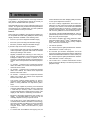
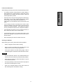
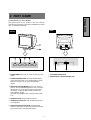
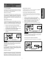
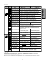
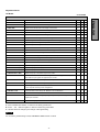
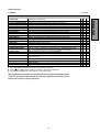
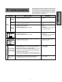
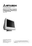
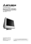
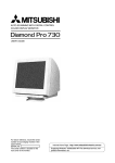
User’s Guide Compaq P710 Color Monitor Compaq P910 Color Monitor Compaq P1210 Color Monitor CONTENTS Features ............................................................ 1 Internal Preset Memory Capability ................... 3 Power Management Function .......................... 3 DDC .................................................................. 3 Location Considerations .................................. 4 Cleaning Your Monitor ..................................... 4 Unpacking ........................................................ 5 Tilt/Swivel Base ............................................... 5 Screen Position Adjustment ........................ 5 Quick Operation Chart ..................................... 5 2. PART NAME Control Names ................................................. 1 3. INSTALLATION AND CONNECTION AC Power Connection ...................................... 1 Signal Cable Connection ................................. 1 Connecting to VGA Compatible System .......... 1 Connecting to Two Computers(22" Model) ...... 1 Installation of USB Function ............................. 3 4. OSD(On Screen Display) FUNCTIONS How to adjust the screen .................................. 1 Adjustment Items (22" Model) ......................... 2 Adjustment Items (19" Model) .......................... 5 Adjustment Items (17" Model) .......................... 8 WARNING! This product is not designed for use in life support devices and Compaq Computer Corporation makes no representations to the contrary. Life support devices are those devices which are used to measure, diagnose, or evaluate the tissue, systems or functions of the human body; or other devices employed to support or sustain life or good health. 5. TROUBLESHOOTING 6. SPECIFICATIONS 22" Model .......................................................... 1 19" Model .......................................................... 2 17" Model .......................................................... 3 7. APPENDIX Monitor Signal Input Connector (DB9-15P) ..... 1 SC-B104 Signal Cable ..................................... 1 Trademark 2000 Compaq Computer Corporation. COMPAQ and the Compaq logo are registered in the U.S. Patent and Trademark Office. Microsoft, Windows, and Windows NT are trademarks of Microsoft Corporation. All other product names mentioned herein may be trademarks of their respective companies. Compaq shall not be liable for technical or editorial erros or omissions contained herein. The information in this document is subject to change without notice. First Edition August 2000. ENERGY STAR is a U.S. registered mark. -1- ENGLISH 1. INTRODUCTION 1 INTRODUCTION • For use in a variety of applications, the monitor complies with UL 1950, CSA C22.2 No.950 and EN60950 for safety, FCC Class-B, VCCI Class-B and EN55022 Class-B for EMI, MPR-II, ISO 9241-3, ISO9241-7 and ISO9241-8 for ergonomics. The monitor also complies with TCO’99 guideline for environmental safe use. • The world's standard DIAMONDTRON NF CRT upgraded with improved focus and convergence for super sharp and pure picture images. • The monitor complies with Video Electronics StanTM TM dards Association (VESA ) DDC 1/2B(EDID) specification. If your computer is Plug & Play compliant setup will be done automatically. • The monitor provides: • fine 0.25mm aperture grille pitch/Maximum addressable resolution of 1600 x 1200 (17") • fine 0.24mm (for Northern hemisphere and 0.25/ 0.27mm for Southern hemisphere aperture grille pitch/ Maximum addressable resolution of 1920 x 1440 (19") • fine 0.24mm aperture grille pitch/Maximum addressable resolution of 2048 x 1536 (22") • The monitor has a contrast enhancement function (FPM: Fine Picture Mode) to accentuate pictures and graphical image. This guide tells you how to connect, adjust and care for your monitor. This guide also provides technical specifications and instructions for troubleshooting any basic problems you may experience with your monitor. Features This monitor is an intelligent, microprocessor-based monitor compatible with most analog RGB (Red, Green, Blue) display standards available in the following sizes: • • • 45 cm/17" (41cm/16" Diagonal Viewable Image) 50 cm/19" (46 cm/18" Diagonal Viewable Image) 55cm/22" (51cm/20" Diagonal Viewable Image) It provides crisp text and vivid color graphics. • • The monitor’s wide auto-scanning compatibility range makes it possible to upgrade video cards or software without purchasing a new monitor. Digitally controlled auto-scanning is done using an internal microprocessor. The microprocessor-based intelligence allows the monitor to operate in each frequency mode with the precision of a fixed frequency monitor. The monitor operates in the following frequencies: • 17" Monitor - horizontal scan frequencies between 30kHz and 96kHz, and vertical scan frequencies between 50Hz and 130Hz • 19" Monitor - horizontal scan frequencies between 30kHz and 108kHz, and vertical scan frequencies between 50Hz and 140Hz • 22" Monitor - horizontal scan frequencies between 30kHz and 121kHz, and vertical scan frequencies between 50Hz and 160Hz. • The monitor contains resident memory for pre-programmed screen display standards and is also capable of storing additional user adjustment parameters. • The monitor is capable of producing a non-interlaced maximum addressable resolution format of 1600 dots x 1200 lines (17" monitor), 1920 x 1440 lines (19" monitor) and 2048 dots x 1536 lines (22" monitor). This display is well suited for windowing environments. • Because of the analog signal inputs, the monitor can display an unlimited palette of colors that can be manually adjusted to suit your specific needs. • The monitor has a power management function accorded to VESATM-DPMSTM-standard. To save energy, the monitor must be connected to a system compliant TM TM with the VESA -DPMS -standard. (Refer to your computer and/or video card instructions for proper operation.) • To ensure ease of installation and ongoing use, the -2- ENGLISH monitor features On Screen Display (OSD) of all monitor set-up and adjustment functions. Congratulations on your purchase of the high resolution color monitor. We designed this monitor to provide you with years of reliable trouble-free operation. 17" Model To minimize adjustment needs, the factory has preset popular display standards into the monitor, as shown in Table 1. If any of these display standards are detected by the microprocessor, the picture size and position are automatically adjusted. All of the factory presets may be overwritten by adjusting the user controls. This monitor is capable of automatically storing up to 15 additional display standards (22" model) or 16 additional display standards (17" and 19" models). The new display information must differ from any of the existing display standards by at least 1kHz for the horizontal scan frequency or 1Hz for the vertical scan frequency or the sync signal polarities must be different. PRESET TIMING 640 x 480 N.I. 640 x 480 N.I. 720 x 400 N.I. 800 x 600 N.I. 800 x 600 N.I. 1024 x 768 N.I. 1024 x 768 N.I. 1152 x 870 N.I. 1280 x 1024 N.I. 1280 x 1024 N.I. 1600 x 1200 N.I. Fh(kHz) Fv (Hz) 31.5 60.0 43.3 85.0 31.5 70.1 46.9 75.0 53.7 85.1 60.0 75.0 68.7 85.0 68.7 75.1 80.0 75.0 91.1 85.0 93.7 75.0 Polarity H – – + + + + – + + + V – – + + + + + – + + + Table 1. Memory Buffer Factory Presets 22" Model PRESET TIMING 640 x 480 640 x 480 720 x 400 800 x 600 800 x 600 1024 x 768 1024 x 768 1152 x 870 1280 x 1024 1280 x 1024 1280 x 1024 1600 x 1200 1600 x 1200 1792 x 1344 1792 x 1344 1800 x 1350 1920 x 1440 1920 x 1440 Power Management Function N.I. N.I. N.I. N.I. N.I. N.I. N.I. N.I. N.I. N.I. N.I. N.I. N.I. N.I. N.I. N.I. N.I. N.I. Fh(kHz) Fv (Hz) 31.5 60.0 43.3 85.0 31.5 70.1 46.9 75.0 53.7 85.1 75.0 75.1 68.7 85.0 68.7 75.1 64.0 60.0 80.0 75.0 91.1 85.0 93.8 75.0 106.3 85.0 83.6 60.0 106.3 75.0 120.4 85.0 90.0 60.0 112.5 75.0 Polarity H V – – + + + + + + + + + – – + + + + + + + + + + + + + + The monitor has a power management function which reduces the power consumption of the monitor when not in use. The power saving mode is invoked by a VESA DPMScompliant computer. Check your computer's manual for setting this function. 22" Model Mode Normal Power Saving Mode 140 W < or = 5 W Green Amber 19" Model Mode Normal Power Saving Mode Power Power-On Indicator 120 W < or = 5 W Green Amber 17" Model 19" Model PRESET TIMING 720 x 400 640 x 480 640 x 480 800 x 600 800 x 600 1024 x 768 1024 x 768 1152 x 870 1280 x 1024 1280 x 1024 1792 x 1344 1920 x 1440 1600 x 1200 1600 x 1200 Power Power-On Indicator (with no USB operation) N.I. N.I. N.I. N.I. N.I. N.I. N.I. N.I. N.I. N.I. N.I. N.I. N.I. N.I. Fh(kHz) Fv (Hz) 31.5 70.0 31.5 60.0 43.3 85.0 46.9 75.0 53.7 85.1 60.0 75.0 68.7 85.0 68.7 75.1 80.0 75.0 91.1 85.0 106.3 75.0 90.0 60.0 93.8 75.0 106.3 85.0 Mode Polarity H V + – – – + + + + + + + + – – + + + + + + + + + + Normal Power Saving Mode Power Power-On Indicator 95 W < or = 5 W Green Amber DDC TM TM The monitor includes the VESA DDC 1 and DDC 2B feature. DDC (Display Data Channel) is a communication channel over which the monitor automatically informs the computer system about its capabilities (e.g. each supported resolution with its corresponding timing). DDC is routed through previously unused pins of the 15-pin VGA connector. The system will “Plug and Play” if both monitor and computer implement the DDC protocol. -3- ENGLISH Internal Preset Memory Capability Location Considerations When setting up and using the monitor, keep the following in mind: For optimum viewing, avoid placing the monitor against a bright background or where sunlight or other light sources may reflect on the display area of the monitor. Place the monitor just below eye level. • Place the monitor away from strong magnetic or electromagnetic fields, such as high capacity transformers, electric motors, large current power lines, steel pillars, etc.... Magnetism can cause distortion in the picture and/or color purity. • Avoid covering the slots or openings of the monitor. Allow adequate ventilation around the monitor so the heat from the monitor can properly dissipate. Avoid putting the monitor into any enclosure that does not have adequate ventilation. • Avoid exposing the monitor to rain, excessive moisture, or dust, as this can cause a fire or shock hazard. • Avoid placing the monitor, or any other heavy object, on the power cord. Damage to the power cord can cause a fire or electrical shock. • When transporting the monitor, handle it with care. ENGLISH • Cleaning Your Monitor When cleaning the monitor, please follow these guidelines: • Always unplug the monitor before cleaning. • Wipe the screen and cabinet front and sides with a soft unspoil cloth to prevent causing imperfections. • If the screen requires more than dusting, apply water or neutral detergent to a soft cloth to clean the monitor screen. CAUTION • Do not use benzene, thinner or any volatile substances to clean the unit as the finish may be permanently marked. • Never leave the monitor in contact with rubber or vinyl for an extended time period. • Do not spray directly on the screen as cleaner may drip into the monitor and damage the circuitry. • Never use an abrasive cleaner on the screen surface as this will damage the anti-reflection coating. -4- Quick Operation Chart After you unpack the box you should have all of the items indicated below. Save the box and packing materials in case you transport the monitor. To summarize the steps in connecting your computer with the color monitor and setting the necessary controls and switches, refer to the chart below. 2 1 3 Connect the color monitor and computer with the necessary cords and cables. See Section 3. INSTALLATION AND CONNECTION 5 4 Turn on the color monitor. 1. Color Monitor 2. AC Power Cord 3. Signal Cable 4. User's Guide (this document) 5. USB Upstream Cable (22" model only) Turn on the computer. Tilt/Swivel Base The monitor comes with a tilt/swivel base. This enables you to position the monitor at the best angle and tilt for maximum viewing comfort. Set the controls. See Section 4. OSD(On Screen Display) FUNCTIONS Screen Position Adjustment OK Adjust the tilt and rotation of the monitor by placing your hands at opposite sides of the case. You can adjust the monitor 90 degrees right or left, 10 degrees up or 5 degrees down (22" model), or 15 degrees up or 5 degrees down (17" and 19" models) as shown below. If a problem appears. OK See Section 5. TROUBLESHOOTING If the problem persists. 22" Model 10 90 90 Call for your authorized Compaq Product Support. 5 17" and 19" Models 15 90 90 5 CAUTION Keep your fingers away from the pivot area of the tilt/swivel base. -5- ENGLISH Unpacking 2 PART NAME ENGLISH Control Names (17" & 19" Models) See figures below for the location of the user controls, indicator and connectors. Each part is identified by number and is described individually. REAR FRONT D-SUB D-sub 7. AC POWER CONNECTOR 1. POWER SWITCH: A push-on / push-off switch for AC power. 8. SIGNAL INPUT CONNECTOR (DB9-15P) 2. POWER-ON INDICATOR: This indicator illuminates green when AC power is on, and illuminates amber when the monitor is in the power management modes. 3. FPM (FINE PICTURE MODE): Push to turn FPM on and off. The normal(default) status is "off", but turning this function "on" may improve camera type image renderings. Select the status which provides the most pleasing image. Note that only standard color is selected when FPM is on. 4. DOWN BUTTON: Push to select group icon. 5. ITEM SELECT BUTTON: Push to select the item icon to be adjusted. 6. FUNCTION ADJUST BUTTONS: Push the adjust buttons to adjust the function that has been selected by the down button and item select button. -1- Control Names (22" Model) See figures below for the location of the user controls, indicator and connectors. REAR FRONT FRONT ENGLISH SIGNAL-A SIGNAL-B 1/2 3 SIGNAL-A SIGNAL-B 1/2 3 9 7. AC POWER CONNECTOR 1. POWER SWITCH: A push-on / push-off switch for AC power. 8. SIGNAL INPUT CONNECTOR (SIGNAL A):DB9-15P 2. POWER-ON INDICATOR: This indicator illuminates green when AC power is on, and illuminates amber when the monitor is in the power management modes. 9. SIGNAL INPUT CONNECTOR (SIGNAL B):DB9-15P 3. INPUT CONNECTOR SELECT/OSD OFF BUTTON: 10. USB UPSTREAM PORT: To connect to a USB equipped computer for Monitor Control Function. • • Without OSD screen, push to select the signal input connector, SIGNAL A or B. With OSD screen, push to turn the OSD screen off. 11. USB DOWNSTREAM PORT: To connect to USB equipped peripherals, e.g. USB camera, keyboard, printer, etc. If only one input is used, the monitor will select it automatically. 4. DOWN BUTTON: Push to select group icon. 5. ITEM SELECT BUTTON: Push to select the item icon. 6. FUNCTION ADJUST BUTTONS: Push the adjust buttons to adjust the image on the screen. -2- 3 INSTALLATION AND CONNECTION Signal Cable Connection On the back of the monitor two kinds of plug-in connections are provided: AC power connector for the AC input, DB915P connector for video signal input. The DB9-15P(VGA) connector is provided for compatible analog RGB outputs from your computer. Connecting to VGA Compatible System AC Power Connection The figure below shows the SC-B104 cable connection to the Video Graphics Array (VGA) port in any VGA compatible system. One end of the AC power cord is connected to the AC power connector on the back of the monitor. The other end is plugged into a properly grounded three-prong AC outlet. The monitor’s auto-sensing power supply can automatically detect 100-120V AC or 220-240V AC and 50 or 60Hz. 1. 2. Signal Cable Connection 3. The attached signal cable provides a DB9-15P connector for the VGA compatible analog RGB outputs on your computer. The figure below shows the included signal cable connection to the Video Graphics Array (VGA) port. 4. 5. 1. 2. 3. 4. 5. ENGLISH 17" and 19" Models Power off, both the monitor and the computer. Connect the one end of the SC-B104 cable to the DB915P connector on the VGA controller card. Connect the other end of the SC-B104 cable to the DB9-15P receptacle on the back of the monitor. Power on the monitor, then the computer. After using the system, power off the monitor, then the computer. Computer Power off, both the monitor and the computer. Connect one end of the signal cable to the DB9-15P connector on the VGA controller card. Connect the other end of the signal cable to the DB915P receptacle on the back of the monitor. Power on the monitor, then the computer. After using the system, power off the monitor, then the computer. SIGNAL-A SIGNAL-B 1 2 VGA Compatible System 3 SIGNAL-A SIGNAL-B Cable SC-B104 Power Cord CAUTION Computer The socket-outlet shall be installed near the equipment and shall be easily accessible. During servicing, disconnect the plug from the socket-outlet. VGA Compatible System D-sub D-sub DB9-15P Connecting to two computers (22" Model) The figure below shows the connection to two computers. Power Cord Cable SC-B104 CAUTION The socket-outlet shall be installed near the equipment and shall be easily accessible. During servicing, disconnect the plug from the socket-outlet. D-SUB D-SUB B Computer B 22" Model On the back of the monitor three kinds of plug-in connections are provided: AC power connector for the AC input, and two DB9-15P connectors for video signal input and USB ports for USB communication. SIGNAL-A Computer A SIGNAL-B VGA Cable SC-B104 AC Power Connection One end of the AC power cord is connected to the AC power connector on the back of the monitor. The other end is plugged into a properly grounded three-prong AC outlet. The monitor’s auto-sensing power supply can automatically detect 100-120V AC or 220-240V AC and 50 or 60Hz. -1- 22" Model USB System Basic Application ENGLISH REAR Power Cord SIGNAL-A SIGNAL-B 21 3 DownstreamPorts SIGNAL-A SIGNAL-B 1 2 3 USB Cable Upstream Port Signal Cable Computer Scanner Camera Keyboard NOTE The computer is required to have Windows® 98 or later installed and USB functions. -2- Installation of USB Function 1. Power on the display monitor and then the computer. 2. Start "Enumeration" from the Windows® Desktop. NOTE NOTE • During the enumeration of the USB Hub, connect the keyboard and mouse, to the computer and not to the downstream ports on the display monitor. After the enumeration, the keyboard and mouse can be used by connecting to the downstream ports, if they are USBcompliant. • Do not unplug the USB cable during the enumerations. (1) Connect the computer and the display monitor with an USB cable. The screen below will appear. (2) Click “Next”. (3) Click “Finish” on the second screen to complete the enumeration of the USB HUB. You can confirm that the USB HUB is successfully enumerated with the following method. • (a) Disconnect and connect the USB cable to the upstream port of the display monitor. (b) Cycle power of the display monitor off then on. Open “Device Manager” tab in “System” property under “Control Panel”. Confirm that “Generic USB HUB” is listed in “Universal Serial Bus Controller”. If you can’t confirm it, re-enumerate the USB HUB again by following (a) or (b). -3- If the mark appears with “Generic USB HUB”, then enumeration was unsuccessful. Select “Generic USB HUB” marked with mark and click “Remove” and “Refresh”. After that, the enumeration is automatically started. NOTE The enumeration of USB HUB may be necessary for each USB port on the computer. ENGLISH The following procedure permits your computer to recognize or "enumerate"(A USB term) the USB HUB. 4 OSD (On Screen Display) How to adjust the screen (5) Adjust by pressing or button. The monitor has an OSD(On Screen Display) function. The following procedure shows how to adjust the screen using the OSD function. (6) If you don't press any button for about 12 seconds, the OSD screen will disappear. (1) Turn on the monitor. The 22" model OSD can be turned off quickly by pressing the OSD OFF button. (2) Press button screen. to display the OSD CONTRAST (3) Select the group icon on Main Menu by pressing . CONTRAST Main Menu (4) Select the item icon on Sub Menu by pressing button. Sub Menu CONTRAST NOTE When pressing both and buttons simultaneously, moving direction of item selection becomes reverse. -1- ENGLISH FUNCTIONS Adjustment Items 22" Model Items MOIRE CANCEL LEVEL CLAMP PULSE POSITION VIDEO LEVEL DEGAUSS POWER SAVE CONTROL LOCK OSD POSITION ALL RESET GTF AUTO ADJUST DIAGNOSIS LANGUAGE Function Adjusts the contrast level. Adjusts the black level of the screen Select the desired color from Color 1, Color 2, and Color 3 presets. Adjusts the red-color balances for the selected color. Adjusts the green-color balances for the selected color. Adjusts the blue-color balances for the selected color. Adjusts the color temperature of the image on the screen. Restores the each color gain and color temperature to the factory preset. Adjusts the horizontal size of the image on the screen. Adjusts the horizontal position of the image on the screen. Adjusts the vertical size of the image on the screen. Adjusts the vertical position of the image on the screen. Straightens the left and right sides of the image on the screen. Adjusts the parallelism of the left and right sides of the image on the screen. Adjusts the pincushioning at the top corners of the screen. Adjusts the pincushioning at the bottom corners of the screen. Adjusts the curvature of the left and right sides of the image on the screen. Adjusts the vertical slant or tilt of the screen image. Centers the linearity of the vertical axis of the screen. Adjusts the linearity of the vertical axis of the screen. Adjusts the rotation of the image on the screen. Zooms the screen to all sides. Restores to the factory preset level.(See "NOTE" below.) Selects the status which provides the most pleasing image. Adjusts the horizontal alignment of the red, green and blue beams. Adjusts the vertical alignment of the red, green and blue beams. Adjusts the purity of the top-left corners of the screen. Adjusts the purity of the top-right corners of the screen. Adjusts the purity of the bottom-left corners of the screen. Adjusts the purity of the bottom-right corners of the screen. When setting to ON, the moire level on the screen can decreased by the MOIRE CANCEL LEVEL. Adjusts the moire level on the screen. Uses this function to eliminate excessive green or white background that may occur when both Sync-On-Green and external sync signals are applied to the monitor. Selects video level 1.0V or 0.7V. (0.7V Standard) Eliminates possible color shading or impurity. When setting to ON, the power consumption of the monitor will be reduced when not in use if your computer is set for power management. Locks the OSD function except for "BRIGHT" and "CONTRAST". Moves the OSD screen position. Restores all items to the factory preset level.(See "NOTE" below.) Adjusts the screen size and distortion automatically. Indicates the current scanning frequency, factory or user preset timing number, and signal input connector. Selects the language used on OSD screen. A. Press "GEOMETRY RESET" to restore to the factory preset level. B. Press and buttons together, to restore to the factory preset level. C. Press "ALL RESET" to restore to the factory preset level. D. Set data does not change by the change of the signal timing. If a non-Factory Preset timing is used, "GEOMETRY RESET" and "ALL RESET" do not work. -2- A X X X X X X X X X X X X X - B C D X X X X X X X X X X X X X X X X X X X X X X X X X X X X X X X X X X X X X X X X X X X X X X X X X X X X X X X X X X - - - - X X X X - X X X X X X X X X X X X X - X X X ENGLISH CONTRAST BRIGHT COLOR NO R-GAIN G-GAIN B-GAIN COLOR TEMPERATURE COLOR RESET HORIZ-SIZE HORIZ-PHASE VERT-SIZE VERT-POSITION PINCUSHION KEYSTONE TOP-PIN BOTTOM-PIN PIN-BALANCE KEY-BALANCE VERT-LIN-BALANCE VERT-LIN ROTATION ZOOM GEOMETRY RESET FINE PICTURE MODE HORIZ-CONVERGENCE VERT-CONVERGENCE CORNER PURITY (TL) CORNER PURITY (TR) CORNER PURITY (BL) CORNER PURITY (BR) MOIRE CANCEL X:Available 22" Model Group Icon Item Icon Item BRIGHT Press the Plus Button To decrease the contrast. To increase the contrast. To decrease the brightness. To increase the brightness. COLOR NO To select color 1, color 2, color 3. R-GAIN To decrease red color level of the color mode selected by "COLOR NO". To increase red color level of the color mode selected by "COLOR NO". G-GAIN To decrease green color level of the color mode selected by "COLOR NO". To increase green color level of the color mode selected by "COLOR NO". B-GAIN To decrease blue color level of the color mode selected by "COLOR NO". To increase blue color level of the color mode selected by "COLOR NO". COLOR TEMPERATURE To decrease the color temperature of the color mode selected by "COLOR NO". To increase the color temperature of the color mode selected by "COLOR NO". To restore the color-gain and color temperature of the color mode selected by "COLOR NO" to the factory preset. HORIZ-SIZE To narrow the width of the image on the screen. To expand the width of the image on the screen. HORIZ-PHASE To move the image on the screen to the left. To move the image on the screen to the right. VERT-SIZE To narrow the height of the image on the screen. To expand the height of the image on the screen. COLOR RESET VERT-POSITION PINCUSHION KEYSTONE To move the image down. To collapse the center of the image. To decrease the width at the top of the screen image and to increase the width at the bottom. To move the image up. To expand the center of the image. To increase the width at the top of the screen image and to decrease the width at the bottom. TOP-PIN To expand the width of the screen image near the corners of top. To narrow the width of the screen image near the corners of top. BOTTOM-PIN To expand the width of the screen image near the corners of bottom. To narrow the width of the screen image near the corners of bottom. PIN-BALANCE To move the top and bottom of the screen image to the right. To move the top and bottom of the screen image to the left. To make the screen slant to the left. To vertically expand the bottom of the screen and compress the top. To vertically compress the center of the screen and expand the top and bottom. To make the screen slant to the right. KEY-BALANCE VERT-LIN-BALANCE VERT-LIN To vertically compress the bottom of the screen and expand the top. To vertically expand the center of the screen and compress the top and bottom. ROTATION To rotate the image counterclockwise. To rotate the image clockwise. ZOOM To narrow the screen to all sides. To expand the screen to all sides. To restore to factory preset level. GEOMETRY RESET -3- ENGLISH CONTRAST Press the Minus Button 22" Model Group Icon Item Icon Press the Minus Button Press the Plus Button Item FINE PICTURE MODE To select the status which provides the most pleasing image. To adjust the horizontal beam alignment on the full screen area. VERT-CONVERGENCE To adjust the vertical beam alignment on the full screen area. CORNER PURITY(TL) To adjust the purity condition on the top-left corner. CORNER PURITY(TR) To adjust the purity condition on the top-right corner. CORNER PURITY(BL) To adjust the purity condition on the bottom-left corner. CORNER PURITY(BR) To adjust the purity condition on the bottom-right corner. MOIRE CANCEL To select the Moire Cancel mode off. To select the Moire Cancel mode on. MOIRE CANCEL LEVEL To decrease the level of the moire-clear wave. CLAMP PULSE POSITION VIDEO LEVEL To eliminate an excessive green or white-back ground that may occur when both Sync-On-Green and external sync signals are applied to the monitor. To clamp the video signal at the front of the H-Sync pulse. To clamp the video signal at the back of the H-Sync pulse. To select 1.0V of video input. To select 0.7V of video input. To eliminate possible color shading or impurity due to magnetic effects. DEGAUSS POWER-SAVE To select the constant power consumption mode. To select the power-save mode. (Your computer must be set for power management.) CONTROL LOCK To unlock the OSD function. To lock the OSD function except for "BRIGHT" and "CONTRAST". OSD POSITION To move the OSD screen position To move the OSD screen in a counter clockwise direction. position in a clockwise direction. To restore all items to the factory preset. ALL RESET To adjust screen size, position and distortions automatically. GTF AUTO ADJUST DIAGNOSIS LANGUAGE To show the current scanning frequency, Preset No., and signal input connection. To choose the language used on OSD. ENG.....English, FRA.....French, ESP.....Spanish, ITA.....Italian, GER.....German, JPN.....Japanese CONTROL LOCK: This is to lock the OSD function to keep the OSD screen image you set. Press plus button to lock the OSD function. You can adjust only "BRIGHT" and "CONTRAST" at the condition. Press minus button to unlock the locked condition. GTF: This function is available when the computer has the GTFTM function according to the VESA®GTFTM standard. -4- ENGLISH HORIZ-CONVERGENCE Adjustment Items 19" Model X = Available Items Function A B C Adjusts the contrast level. X X BRIGHT Adjusts the black level of the screen X X COLOR TEMPERATURE Adjusts the color temperature of the image on the screen. X X HORIZ-SIZE Adjusts the horizontal size of the image on the screen. X HORIZ-PHASE Adjusts the horizontal position of the image on the screen. X VERT-SIZE Adjusts the vertical size of the image on the screen. X VERT-POSITION Adjusts the vertical position of the image on the screen. X PINCUSHION Straightens the left and right sides of the image on the screen. X KEYSTONE Adjusts the parallelism of the left and right sides of the image on the screen. X TOP-PIN Adjusts the pincushioning at the top corners of the screen. X BOTTOM-PIN Adjusts the pincushioning at the bottom corners of the screen. X PIN-BALANCE Adjusts the curvature of the left and right sides of the image on the screen. X KEY-BALANCE Adjusts the vertical slant or tilt of the screen image. X ROTATION Adjusts the rotation of the image on the screen. GEOMETRY RESET Restores to the factory preset level.(See "NOTE" below.) HORIZ-STATIC X - - - Adjusts the horizontal alignment of the red, green and blue beams. X X VERT-STATIC Adjusts the vertical alignment of the red green and blue beams. X X MOIRE CANCEL LEVEL Adjusts the moire level on the screen. X CORNER PURITY (TL) Adjusts the purity of the top-left corners of the screen. X X CORNER PURITY (TR) Adjusts the purity of the top-right corners of the screen. X X CORNER PURITY (BL) Adjusts the purity of the bottom-left corners of the screen. X X CORNER PURITY (BR) Adjusts the purity of the bottom-right of the screen. X X CLAMP PULSE POSITION Uses this function to eliminate excessive green or white background that may occur - - when external sync signals are applied to the monitor. VIDEO LEVEL Selects video level 1.0V or 0.7V. (0.7V Standard) DEGAUSS Eliminates possible color shading or impurity. POWER-SAVE When setting to ON, the power consumption of the monitor will be reduced when not in use - X if your computer is set for power management. CONTROL LOCK Locks the OSD function except for "BRIGHT" and "CONTRAST". X OSD POSITION Moves the OSD screen position. X DIAGNOSIS Indicates the current scanning frequency, factory or user preset timing number, and - - - signal input connector. LANGUAGE Selects the language used on OSD screen. A. Press "GEOMETRY RESET" to restore to the factory preset level. B. Press - and + buttons together, to restore to the factory preset level. C. Set data does not change by the change of the signal timing. NOTE If a non-Factory Preset timing is used, "GEOMETRY RESET" does not work. -5- X ENGLISH CONTRAST 19" Model Group Icon Item Icon Item BRIGHT To decrease the brightness. To increase the brightness. COLOR TEMPERATURE To decrease the color temperature. To increase the color temperature. HORIZ-SIZE To narrow the width of the image on the screen. To expand the width of the image on the screen. HORIZ-PHASE To move the image on the screen to the left. To move the image on the screen to the right. VERT-SIZE To narrow the height of the image on the screen. To expand the height of the image on the screen. To move the image down. To move the image up. To collapse the center of the image. To expand the center of the image. To decrease the width at the top of the screen image and to increase the width at the bottom. To increase the width at the top of the screen image and to decrease the width at the bottom. TOP-PIN To expand the width of the screen image near the corners of top. To narrow the width of the screen image near the corners of top. BOTTOM-PIN To expand the width of the screen image near the corners of bottom. To narrow the width of the screen image near the corners of bottom. PIN-BALANCE To move the top and bottom of the screen image to the right. To move the top and bottom of the screen image to the left. KEY-BALANCE To make the screen slant to the left. To make the screen slant to the right. To rotate the image counterclockwise. To rotate the image clockwise. PINCUSHION KEYSTONE ROTATION To restore to factory preset level. GEOMETRY RESET -6- ENGLISH To increase the contrast. VERT-POSITION GEOMETRY Press the Plus Button To decrease the contrast. CONTRAST SCREEN Press the Minus Button 19" Model Group Icon Item Icon Item Press the Minus Button Press the Plus Button To adjust the horizontal beam alignment on the full screen area. VERT-STATIC To adjust the vertical beam alignment on the full screen area. MOIRE CANCEL LEVEL To decrease the level of the moire-clear wave. CORNER PURITY(TL) To adjust the purity condition on the top-left corner. CORNER PURITY(TR) To adjust the purity condition on the top-right corner. CORNER PURITY(BL) To adjust the purity condition on the bottom-left corner. CORNER PURITY(BR) To adjust the purity condition on the bottom-right corner. VIDEO CLAMPPULSEPOSITION VIDEO LEVEL To eliminate an excessive green or white-back ground that may occur when external sync signals are applied to the monitor. To clamp the video signal at the back of the H-Sync pulse. To clamp the video signal at the front of the H-Sync pulse. To select 1.0V of video input. Toeliminatepossiblecolorshadingorimpurity due to magnetic effects. DEGAUSS POWER-SAVE CONTROL LOCK To select 0.7V of video input. To select the constant power consumption mode. To select the power-save mode. (Your computer must be set for power management.) To permit all OSD adjustments. To lock the OSD function except for "BRIGHT"and"CONTRAST". MISC. OSD POSITION DIAGNOSIS LANGUAGE To move the OSD screen position To move the OSD screen position in a clockwise direction. in a counter clockwise direction. Shows the current scanning frequency and Preset No.. To choose the language used on OSD. ENG......English, FRA......French, GER......German, JPN......Japanese -7- ESP......Spanish, ENGLISH HORIZ-STATIC Adjustment Items 17" Model X: Available Items VIDEO LEVEL DEGAUSS POWER-SAVE CONTROL LOCK DIAGNOSIS LANGUAGE Adjusts the contrast level. Adjusts the black level of the screen. Adjusts the color temperature of the image on the screen. Adjusts the horizontal size of the image on the screen. Adjusts the horizontal position of the image on the screen. Adjusts the vertical size of the image on the screen. Adjusts the vertical position of the image on the screen. Straightens the left and right sides of the image on the screen. Adjusts the parallelism of the left and right sides of the image on the screen. Adjusts the pincushioning at the top corners of the screen. Adjusts the pincushioning at the bottom corners of the screen. Adjusts the curvature of the left and right sides of the screen image. Adjusts the vertical slant or tilt of the screen image. Adjusts the rotation of the image. Restore to the factory preset level. (Only function on factory preset timing) Adjusts the moire level on the screen. Use this function to eliminate excessive green or white background that may occur when external sync signals are applied to the monitor. Selects video level 1.0V or 0.7V. (0.7V Standard) Eliminates possible color shading or impurity. When setting to ON, the power consumption of the monitor will be reduced when not in use. Locks the OSD function to keep the screen you desired. Indicates the current scanning frequency and factory or user preset timing number. Selects the language used on OSD screen. A. Press "GEOMETRY RESET" to restore to the factory preset level. B. Press and buttons together, to restore to the factory preset level. C. Set data does not change by the change of the signal timing. *Moire is a series of wavy patterns caused by the interference between the aperture grille of the CRT and the raster generated by the video card. Adjust the level to the minimum value at which moire is no longer observed. -8- A B C X X X X X X X X X X X X X X X X - X - - X - X X - - X ENGLISH CONTRAST BRIGHT COLOR TEMPERATURE HORIZ-SIZE HORIZ-PHASE VERT-SIZE VERT-POSITION PINCUSHION KEYSTONE TOP-PIN BOTTOM-PIN PIN-BALANCE KEY-BALANCE ROTATION GEOMETRY RESET *MOIRE CANCEL LEVEL CLAMP PULSE POSITION Function 17" Model Group Icon Item Icon Item BRIGHT Press the Plus Button To decrease the contrast. To increase the contrast. To decrease the brightness. To increase the brightness. SCREEN COLORTEMPERATURE HORIZ-SIZE To move the image to the left. To move the image to the right. To narrow the height of the image on the screen. To expand the height of the image on the screen. To move the image down. To move the image up. TOP-PIN To collapse the center of the image. To decrease the width at the top of the screen image and to increase the width at the bottom. To expand the width of the screen image near the corners of top. To expand the center of the image. To increase the width at the top of the screen image and to decrease the width at the bottom. To narrow the width of the screen image near the corners of top. BOTTOM-PIN To expand the width of the screen image near the corners of bottom. To narrow the width of the screen image near the corners of bottom. PIN-BALANCE To move the top and bottom of the screen image to the right. To move the top and bottom of the screen image to the left. KEY-BALANCE To make the screen slant to the left. To make the screen slant to the right. HORIZ-PHASE VERT-SIZE VERT-POSITION PINCUSHION KEYSTONE GEOMETRY To decrease the color temperature. To increase the color temperature. When FPM is on, the color temperature is fixed to 9300K and it is not adjustable. To narrow the width of the image To expand the width of the image on the screen. on the screen. ROTATION To rotate the image counterclockTo rotate the image clockwise. wise. To restore to factory preset level. GEOMETRY RESET MOIRE CANCEL LEVEL CLAMPPULSEPOSITION To decrease the level of the moire-clear wave. To eliminate an excessive green or white-back ground that may occur when external sync signals are applied to the monitor. To clamp the video signal at the To clamp the video signal at back of the H-Sync pulse. the front of the H-Sync pulse. VIDEO VIDEO LEVEL To select 1.0V of video input. To eliminate possible color shading or impurity. DEGAUSS POWER-SAVE CONTROL LOCK MISC. To select 0.7V of video input. To select the constant power consumption mode. To select the power-save mode. To permit all OSD adjustments. To lock the OSD function except for "BRIGHT"and"CONTRAST". DIAGNOSIS It shows the current scanning frequency and Preset No. or user mode. LANGUAGE To choose the language used on OSD. ENG......English, ESP......Spanish, GER......German, FRA......French -9- JPN......Japanese, ENGLISH CONTRAST Press the Minus Button 5 TROUBLESHOOTING ITEMS TO CHECK PROBLEM LOCATION • Contrast and brightness controls. • Front • Power switch. • AC power cord disconnected. • Front • Rear • Signal cable disconnected. • Computer power switch. • Power management function is active. • Rear • Computer • Press any key on the keyboard or move the mouse. • Signal cable disconnected. • Computer power switch. • Power management function is active. • Rear • Computer • Press any key on the keyboard or move the mouse. • Input signal frequency range is too high or too low for the monitor to synchronize with. • Check the specification of graphics adapter • Do "GEOMETRY-RESET" or "ALL RESET" for a standard signal. • Adjust HORIZ-SIZE, VERT-SIZE, HORIZ-PHASE, and VERT-POSITION with non-standard signals. • Monitor may not be able to get full-screen image depend on signal. In this case, please select other resolution, or other vertical refresh timing. • Make sure you wait a few seconds after adjusting the size of the image before changing or disconnecting the signal. • Front (OSD) • Front (OSD) • "VIDEO LEVEL" is not at the appropriate position for your graphics adapter output. (0.7v or 1.0Vp-p). • Front (OSD) LED On (Green) LED Off No picture LED On (Amber) The following message appeared. The following message appeared. ATTENTION SIGNAL FREQUENCY IS OUT OF RANGE. FH @ @24.8KHz @24.8KHz FV @ 43.0Hz 43.0 Abnormal picture PLEASE CHANGE SIGNAL TIMING. Display is missing, center shifts, or too small or too large of a display size Display is dark or too bright -1- ENGLISH Before calling your 1-800-OK-COMPAQ for service, please check that the items below are properly connected or set. In case of using a non-standard signal, please check the pin assignments and the signal timing of your computer with the specification outlined in Section 6. SPECIFICATIONS and Section 7. APPENDIX. ITEMS TO CHECK PROBLEM LOCATION Abnormal Picture • Thin vertical black lines on one or both sides of the screen. This minor condition is caused by grille element overlap which can occur during shipping. Black vertical lines are visible on the screen. – Position an open white window over the affected area of the screen and maximize the brightness and contrast controls. This will cause localized heating of the overlap which will clear in a few minutes. Be sure to readjust the brightness and contrast controls back to the normal viewing levels after this procedure. A Two fine horizontal lines are visible on the screen. • B • The 2 very faint thin lines across the screen are normal. They are caused by the aperture grille stabilization filaments(Damper Wires) which are required for all aperture grille CRTs’. • – Aperture Grille Shadow of Damper Wires Electron Gun Damper Wires Shadow of Damper Wires A buzzing sound when power on. Aperture Grille Type • A brief vibration or hum sound that is heard just after power up is normal. This is caused by the automatic degaussing function. This sound will be heard each time the monitor is powered up from a cold start and each time the manual degauss button is used. • – 6 SPECIFICATIONS 22" Model 55cm/22"(51cm/20" Diagonal Viewable Image) Mask type Aperture grille Gun In-line Deflection angle 90° Phosphors Aperture grille pitch Red, Green, Blue EBU (medium short persistence) 0.24mm Phosphor pitch 0.25mm Face Plate Anti-glare, Anti-reflection and Anti-static coating Focusing method Dynamic Beam Forming (DBF) INPUT SIGNAL Video Sync 0.7Vp-p analog RGB Separate H, V sync. SIGNAL INTERFACE Input Connectors Input Impedance DB9-15P x 2 75 Ω (video), 2.2k Ω (sync.) SCANNING FREQUENCY Horizontal Vertical 30 - 121kHz 50 - 160Hz RESOLUTION (HxV) 2048 dots x 1536 lines Non-Interlaced maximum addressable resolution format at 75Hz WARM-UP TIME 30 minutes to reach optimum performance level BRIGHTNESS 100cd/m2, standard full white video signal at 9300K (+ 8MPCD) POWER SOURCE AC100-120/220-240V±10% 50/60Hz 140W (typ.) < 155w (typ.) with USB operation> BLANKING TIME Horizontal > 2.3 µsec (typ.) Vertical > 450 µsec (typ.) DISPLAY SIZE 393mm x 295mm(typ.) ratio 4:3 COLOR 5000K~9300K OPERATING ENVIRONMENT Temperature Humidity 10- 35°C 20 - 80%RH (without condensation) DIMENSIONS (W)19.7inch x (H)19.7inch x (D)19.0inch / (W) 500mm x (H) 500mm x (D) 482mm WEIGHT TILT/SWIVEL Approx. 30kg (66.14 lbs.) Tilt Angle -5° - +10° BASE Swivel Angle Safety ±90° UL1950 (UL), CSA C22.2 No.950 (C-UL) EN60950 (TÜV-GS), NEMKO, SEMKO, DEMKO, FIMKO EMC FCC Class-B, DOC Class-B EN55022 Class-B, VCCI Class-B REGULATIONS X-Ray Other EN50082-1, EN61000-3-2, EN61000-3-3 DHHS, HWC, Röv vom 8.1, 1987 CE-Marking, MPR-II/TCO'91 ISO9241-3, ISO9241-7, ISO9241-8 (TÜV-GS) TCO '99 International ENERGY STAR Program USB Functional Self-powered HUB complying with Universal Serial Bus Interface 1 Upstream port/12 Mbps Specifications Rev 1.0 3 Downstream ports/12 Mbps, 1.5 Mbps (500mA max. per each downstream port) -1- ENGLISH CRT Size 19" Model INPUT SIGNAL SIGNAL INTERFACE SCANNING FREQUENCY RESOLUTION (HxV) 50cm/19"(46cm/18" Diagonal Viewable Image) Mask type Aperture grille Gun In-line Deflection angle 90° Phosphors Red, Green, Blue EBU (medium short persistence) Aperture grille pitch 0.24mm Face Plate Anti-glare, Anti-reflection and Anti-static film Focusing method Video Dynamic Beam Forming (DBF) 0.7 or 1.0Vp-p analog RGB Sync Input Connector Separated H, V sync. or Composite sync DB9 - 15P Input Impedance Horizontal 75 Ω (video), 2.2k Ω (sync.) 30 - 108kHz Vertical 50 - 140Hz 1920dots x 1440lines Non-Interlaced maximum addressable resolution format at 60Hz Recommended Resolution: 1280 dots x 1024 lines at 85Hz WARM-UP TIME 30 minutes to reach optimum performance level BRIGHTNESS 110cd/m2(typ.), standard full white video signal at 9300K (+ 27MPCD) BLANKING TIME Horizontal Vertical DISPLAY SIZE 350mm x 262mm(typ.) COLOR TEMPERATURE POWER SOURCE 5000K~9300K 2.3 µsec (typ.) 450 µsec (typ.) ratio 4:3 OPERATING AC100-120/220-240V±10% 50/60Hz 120W (typ.) Temperature 10 - 35°C (AC220-240V±10% 50/60Hz for Europe) ENVIRONMENT Humidity DIMENSIONS WEIGHT (W)17.9inch x (H)18.2inch x (D)18.0inch / (W) 454mm x (H) 462mm x (D) 456mm Approx. 23.0kg (50.7lbs.) TILT/SWIVEL BASE Tilt Angle Swivel Angle -5° - +15° ±90° Safety UL1950 (UL), CSA C22.2 No.950 (CSA) 20 - 80%RH (without condensation) EN60950 (TÜV-GS), NEMKO, SEMKO, DEMKO, FIMKO EMC FCC Class-B, DOC Class-B, VCCI Class-B For only Europe: REGULATIONS EN55022 Class-B, EN50082-1, EN61000-3-2, EN61000-3-3 X-Ray Other DHHS, HWC, Röv vom 8.1, 1987 CE-Marking, MPR-II/TCO'91 TCO '99, ISO9241-3,-7, and -8 (TÜV-GS) International ENERGY STAR Program -2- ENGLISH CRT Size 17" Model 45cm/17"(41cm/16" Diagonal Viewable Image) Mask type Aperture grille Gun In-line Deflection angle 90° Phosphors Red, Green, Blue EBU (medium short persistence) Aperture grille pitch 0.25mm Face Plate Anti-glare, Anti-reflection and Anti-static film Focusing method Video Dynamic Beam Forming (DBF) 0.7Vp-p analog RGB Sync Input Connector Separated H, V sync. or Composite sync DB9 - 15P SCANNING Input Impedance Horizontal 75 Ω (video), 2.2k Ω (sync.) 30 - 96kHz FREQUENCY Vertical 50 - 130Hz INPUT SIGNAL SIGNAL INTERFACE RESOLUTION (HxV) 1600dots x 1200lines Non-Interlaced maximum addressable resolution format at 75Hz Recommended Resolution: 1024 dots x 768 lines at 85Hz WARM-UP TIME 30 minutes to reach optimum performance level BRIGHTNESS 110cd/m2, standard full white video signal at 9300K (+ 27MPCD) BLANKING TIME Horizontal DISPLAY SIZE 312mm x 234mm(typ.) COLOR TEMPERATURE 5000K~9300K OPERATING AC100-120/220-240V±10% 50/60Hz 95W (typ.) (AC 220-240V + or - 10% 50 Hz for Europe) Temperature 10 - 35°C ENVIRONMENT Humidity DIMENSIONS (W)16.1inch x (H)16.2inch x (D)17.1inch / (W) 410.2mm x (H) 412.6mm x (D) 435.3mm WEIGHT TILT/SWIVEL Approx. 17.5 kg (38.6 lbs.) Tilt Angle -5° - +15° BASE Swivel Angle ±90° Safety UL1950 (UL), CSA C22.2 No.950 (C-UL) EN60950 (TÜV-GS), NEMKO, SEMKO, DEMKO, FIMKO EMC FCC Class-B, DOC Class-B Vertical > or = 2.7µsec (typ.) > or = 500 µsec (typ.) ratio 4:3 20 - 80%RH (without condensation) EN55022 Class-B REGULATIONS X-Ray EN50082-1, EN60555-2, EN61000-3-3 DHHS, HWC, Röv vom 8.1, 1987 Other CE-Marking, MPR-II/TCO'91 TCO '99, ISO9241-3,-7, and -8 (TÜV-GS) International ENERGY STAR Program -3- ENGLISH CRT Size 7 APPENDIX Monitor Signal Input Connector (DB9-15P) Approx. 1.8m (Female) DB9-15P 5 3 4 9 10 15 13 6 6 12 DB9-15P(Male) 12 12 9 13 13 Pin No. 1 RED VIDEO 1 RED 2 GREEN VIDEO 2 GREEN or COMPOSITE SYNC with GREEN VIDEO 3 Signal BLUE GROUND DDC GROUND BLUE VIDEO 4 4 GROUND 5 5 DDC GROUND 6 RED GROUND 6 RED GROUND 7 GREEN GROUND 7 GREEN GROUND 8 BLUE GROUND 8 BLUE GROUND 9 NC 9 NC 10 SYNC GROUND 10 SYNC GROUND 11 GROUND 11 GROUND 12 SDA 12 SDA 13 HORIZONTAL SYNC HORIZONTAL SYNC 14 VERTICAL SYNC(VCLK) 15 SCL 13 or COMPOSITE SYNC 14 VERTICAL SYNC(VCLK) 15 SCL DDC ................... DISPLAY DATA CHANNEL SDA ................... SERIAL DATA SCL .................... SERIAL CLOCK NC ..................... NO-CONNECTION 5 10 10 15 15 PIN ASSIGNMENTS Signal 3 14 14 DB9-15P(Male) PIN ASSIGNMENTS Pin No. 4 3 8 7 11 11 11 MOUNTED ON THE REAR PANEL 2 1 1 2 7 8 14 SC-B104 Signal Cable DDC ............... SDA ................ SCL ................ NC .................. DISPLAY DATA CHANNEL SERIAL DATA SERIAL CLOCK NO-CONNECTION Regulatory Compliance Notices Federal Communications Commission Notice This equipment has been tested and found to comply with the limits for a Class B digital device, pursuant to Part 15 of the FCC Rules. These limits are designed to provide reasonable protection against harmful interference in a residential installation. This equipment generates, uses, and can radiate radio frequency energy and, if not installed and used in accordance with the instructions, may cause harmful interference to radio communications. However, there is no guarantee that interference will not occur in a particular installation. If this equipment does cause harmful interference to radio or television reception, which can be determined by turning the equipment off and on, the user is encouraged to try to correct the interference by one or more of the following measures: • Reorient or relocate the receiving antenna. • Increase the separation between the equipment and receiver. • Connect the equipment into an outlet on a circuit different from that to which the receiver is connected. • Consult the dealer or an experienced radio or television technician for help. Modifications The FCC requires the user to be notified that any changes or modifications made to this device that are not expressly approved by Compaq Computer Corporation may void the user’s authority to operate the equipment. Cables Connections to this device must be made with shielded cables with metallic RFI/ EMI connector hoods in order to maintain compliance with FCC Rules and Regulations. Declaration of Conformity for products marked with the FCC logo - United States only This device complies with Part 15 of the FCC Rules. Operation is subject to the following two conditions: (1) this device may not cause harmful interference, and (2) this device must accept any interference received, including interference that may cause undesired operation. For questions regarding your product, contact: Compaq Computer Corporation P. O. Box 692000, Mail Stop 530113 Houston, Texas 77269-2000 Or, call 1-800- 652-6672 (1-800-OK COMPAQ) For questions regarding this FCC declaration, contact: Compaq Computer Corporation P. O. Box 692000, Mail Stop 510101 Houston, Texas 77269-2000 Or, call (281) 514-3333 Canadian Notice This Class B digital apparatus meets all requirements of the Canadian Interference-Causing Equipment Regulations Avis Canadien Cet appareil numérique de la classe B respecte toutes les exigences du Règlement sur le matériel brouilleur du Canada. European Union Notice Products with the CE Marking comply with both the EMC Directive (89/336/EEC) and the Low Voltage Directive (73/23/EEC) issued by the Commission of the European Community. Compliance with these directives implies conformity to the following European Norms (in brackets are the equivalent international standards): ! EN55022 (CISPR 22) - Electromagnetic Interference ! EN50082-1 (IEC801-2, IEC801-3, IEC801-4) - Electromagnetic Immunity ! EN60950 (IEC950) - Product Safety Japanese Notice Energy Star Monitors that are marked with the Energy Star Logo meet the requirements of the EPA Energy Star program. As an Energy Star Partner, Compaq Computer Corporation has determined that this product meets the Energy Star guidelines for energy efficiency. Specific details on using the Energy Saving features can be found in the energy saver or power management section of the computer manual. 216028-001