1
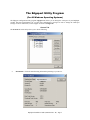
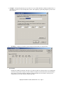
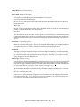
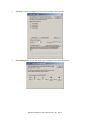
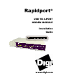
Rapidport
®
USB TO 4-PORT
MODEM MODULE
Installation
Guide
www.digi.com
Table of Contents
Cabling Rapidport........................................................................................1
Installing Rapidport Drivers ........................................................................2
Installing the Rapidport Modems.................................................................3
Interpreting the Status Lights.......................................................................4
The Edgeport Utility Program .....................................................................5
Regulatory & Other Information ...............................................................11
Rapidport
Rapidport offers an easy solution for remote access via Plug-and-Play USB connectivity. This external, userinstallable solution plugs into the USB port of a PC, thin client or server and provides four 56K V.90 modems.
EdgeUSB technology, shipping with Rapidport since 1998, adds Plug-and-Play USB compatibility to Microsoft
Windows NT and Windows NT Embedded system users. The Rapidport gives network users access to Internet
Service Providers (ISP), fax, and other group dial-up applications supported by Windows NT RAS.
Rapidport is a scalable solution – its onboard USB port enables additional units to be stacked and daisy-chained as
modem requirements increase. The downstream port may be used to connect and power any 500mA USB peripheral
device, including Edgeport USB-to-serial converters for instant I/O expansion. Its feature-rich design, extensive
operating system support and reliable performance make Rapidport/4 ideal for mission critical enterprise
applications.
Cabling Rapidport
To connect the cables included with your Rapidport:
1) Connect one end of the power supply* into the back of your Rapidport and the other end into an AC outlet.
2) Connect one end of the phone cord** to Port 1 on the back of the Rapidport and the other end to an analog
phone jack. Repeat for up to four connections (Ports 1-4).
CAUTION: To reduce the risk of fire, use only No. 26 AWG or larger telecommunication line cord.
3a) For a downstream connection, plug the Type A end of the USB cable into the USB port located in the back of
your PC or into an available USB port on a standard hub or into a Digi International Hubport. Plug the Type B
end of the USB cable into the back of the Rapidport.
3b) For an upstream connection, plug the Type A end of the USB cable into Rapidport’s USB Type A slot and
the Type B end of the USB cable into the upstream device (e.g. a Hubport or another Rapidport).
The cabling diagrams on page 10 show both Type A and Type B plugs and receptacles.
To install the necessary drivers, go to the “Installing Rapidport Drivers” section, which starts on this page.
*Power to this product may be supplied by a UL Listed Direct Plug-In Power Unit marked “Class 2” with a
minimum rating of 5 V dc, 2.1 A if used in the U.S. and Canada or a power supply with similar rating and approved
by your local safety code if it is used elsewhere. For polarity, use the following:
**Safety Warning: 1) Never install telephone wiring during a lightning storm. 2) Never install telephone jacks in
wet locations unless the jack is specifically designed for wet locations. 3) This product is to be used with UL and
cUL listed computers. 4) Never touch uninsulated telephone wires or terminals unless the telephone line has been
disconnected at the network interface. 5) Use caution when installing or modifying telephone lines. 6) Avoid using a
telephone (other than a cordless type) during an electrical storm. There may be a remote risk of electrical shock from
lightning. 7) Do not use the telephone to report a gas leak in the vicinity of the leak.
Rapidport Installation Guide (90000665 Rev. B) – Page 1
Installing Rapidport Drivers
For Windows XP and 2003 Server
Note: If your computer is connected to the internet, the latest Microsoft certified drivers will be automatically
downloaded from the Microsoft driver update server.
1) You must be logged into an account with administrator privileges.
2) Insert the “Edgeport Driver” CD version 3.60 or above into your CD-ROM drive.
3) When the Found New Hardware Wizard appears click “Next,” and the drivers will be automatically
installed from the CD
For Windows 2000
1) You must be logged into an account with administrator privileges
2) Insert the “Edgeport Driver” CD version 3.60 or above into your CD-ROM drive.
3) When the Found New Hardware Wizard appears, select Install from a list or specific location
(Advanced) and click Next.
4) Select “Search for a suitable driver for my device” and click Next.
5) Select Specify a location and click Next.
6) Type in <CD drive letter>:\Win2k and click OK.
7) Confirm that Windows is pointing to <CD drive letter>:\Win2k. Then click Next.
Note: Drivers installed from the CD have received “Designed for Windows 2000” certification. Drivers
downloaded from our web site may be pending certification. If so, Windows 2000 will display a warning: Digital
Signature Not Found. Click Yes to continue with driver installation. If you click No you will need to contact Digi
International Technical Support before installing your USB Plus Series product.
8) Windows will then finish installing the driver files.
9) Click Finish to complete the driver installation.
Installation is complete when no more dialogs appear. Your new COM port(s), numbered sequentially following the
existing ports in your system, is/are ready.
For Windows 98
1) Insert the "Edgeport Driver" CD into your CD-ROM drive.
2) After connecting the USB cable, the Add New Hardware Wizard appears. Click Next.
3) Select Search for the best driver for your device and click Next.
4) Select Specify a location and type in <CD drive letter>:\Win98. Then click Next.
5) Confirm that Windows is pointing to <CD drive letter>:\Win98. Click Next. Windows will then copy
over the driver files.
6) Click Finish to complete the driver installation.
Installation is complete when no more dialogs appear. Your new COM port(s), numbered sequentially following the
existing ports in your system, is/are ready.
Rapidport Installation Guide (90000665 Rev. B) – Page 2
For Windows NT 4.0
Because Microsoft does not support USB in NT4.0, Digi International supplies a set of USB drivers that will be
installed along with the necessary Edgeport drivers. NOTE: You must install the drivers using an account that has
administrative privileges!
To install the USB stack and Edgeport drivers:
1) Insert the “Edgeport Driver” CD Version 3.60 or above into your CD-ROM drive.
2) When the welcome dialog appears, click the Install Driver button.
Once the driver installation program has begun, follow the on screen instructions.
3a) If you are installing drivers for the first time: An Information dialog informs you that the installation was
successful. After clicking OK, the installation is complete.
3b) If you are replacing existing Edgeport drivers: Follow the on-screen instructions. Note that, before
beginning the installation of the drivers, all applications with open ports must be closed and all USB
devices unplugged. If you close all the applications and unplug all the USB devices, then you will not need
to reboot for the new drivers to take effect immediately. If any applications are left open or USB devices
plugged in, you may choose to abort the installation or to continue and be required to reboot before the
upgrade can take effect.
Note that because Windows NT 4.0 is not Plug-and-Play, you will not see a pop-up dialog box indicating that new
hardware has been found. You may verify correct installation with the Edgeport Utility (see page 5) or the USB
Status Utility (as described below).
The USB Status Utility (Viewer) can be accessed by clicking the USB icon in your system tray or by clicking on
Start/Programs/Digi USB/USB Status Utility. This utility lists all the USB devices installed on your PC and
provides other relevant information for each device. You may also use this utility to create a log file.
Installing the Rapidport Modems
Before installing a Rapidport modem, ensure that it is connected to your PC and has power.
For Windows XP, 2003 Server, 2000, and 98
1) From the Control Panel, open Modems. (If the Modems Properties dialog appears, click Add in order to view
the Install New Modems dialog.)
2) While in the Install New Modem dialog, click Next and wait while your system searches for new modems.
3) Follow the recommended on-screen instructions.
4) Click Finish to complete installation and return to the Modems Properties dialog.
For Windows NT
1) Open the Edgeport Utility as described on page 5. Each Rapidport is listed with its own serial number.
2) Double click on the new Rapidport to display its COM ports. Note the COM ports associated with this
Rapidport and click OK to close the dialog.
3) From the Control Panel, open Modems.
4) Click Add in order to view the Install New Modems dialog.
5) While in the Install New Modem dialog, click Next.
6) Select a COM port for this Rapidport, click Next. (If you do not know which COM port to select, close the
dialog and follow steps 1 and 2 above.)
7) Note the name of your new modem: Rapidport USB 56K modem. Click Next.
8) Repeat steps 4-7 for each additional COM port. When you have finished, click Cancel.
Rapidport Installation Guide (90000665 Rev. B) – Page 3
Interpreting the Status Lights
Interpreting the System Status Light
Red
This light signifies a loss of USB communication with the host. If the loss is due to unplugging the unit,
when it is reconnected the light will blink red a few moments before turning green. Otherwise, the light
indicates a problem with the drivers, which may need to be reinstalled. The red light will also blink during
installation until the installation is complete.
Amber This light signifies serial port activity on the Rapidport. The yellow light may also flash briefly during
installation.
Green This light indicates that the serial ports have been successfully set up and the Rapidport is operating
normally.
Interpreting the HUB Port Status Light
Green
When on, this light indicates that the downstream connection has power.
Interpreting the Modem Status Lights
RD
TD
CD
TR
Receive Data. This light flashes when data is sent to your computer from the modem. At high speeds light
may appear continuously on.
Transmit Data. This light flashes whenever data or commands are sent to the modem from your computer.
Carrier Detect. This light indicates that the Data Carrier Detect (DCD) signal from the modem to your
computer is on.
Terminal Ready. This light indicates that your computer is ready to send or receive data. It also shows the
Data Terminal Ready (DTR) signal status from your computer.
Rapidport Installation Guide (90000665 Rev. B) – Page 4
The Edgeport Utility Program
(For All Windows Operating Systems)
The Edgeport configuration utility program (edgeport.exe) allows you to manage the serial ports of your Rapidport
product. Note that with Windows NT you must have administrative privileges in order to change the COM port
settings. For more information, see the Support section at www.digi.com.
General Tab
The General tab in this utility allows you to do the following:
•
Information - Check the manufacturing information pertaining to your device.
Digi International
Rapidport Installation Guide (90000665 Rev. B) – Page 5
• Configure - Reassign the physical port on your device to any available Windows COM port number from 1 to
255 and give your device a user friendly Device Name. This capability is particularly helpful if you have more
than one device.
•
Port Flags - Configure performance options and special functionality on a per-port basis.
Low Latency:
Normally the UART will interrupt when the receiver has been idle for 4 character times. (For example 4ms
at 9600) As long as data is being received the UART will continue to buffer them until its internal FIFO is
full (~56 bytes). This flag causes the Edgeport to poll the RX FIFO for received bytes. If any bytes are
available they will be sent to the driver without any delay.
Rapidport Installation Guide (90000665 Rev. B) – Page 6
Remap Baud: (All operating systems)
Setting the baud rate to 1200 baud will result in 230400 baud
Ignore Flush: (Windows NT/2K/XP)
If an application sends IRP_MJ_FLUSH_BUFFERS it will be ignored.
Excerpt from Microsoft documentation:
Drivers of devices with internal caches for data and drivers that maintain internal buffers for data must
handle this request.
When Sent
Receipt of a flush request indicates that the driver should flush the device's cache or its internal buffer, or,
possibly, should discard the data in its internal buffer.
Operation
The driver transfers any data currently cached in the device or held in the driver's internal buffer(s) before
completing the flush request. The driver of an input-only device that buffers data internally might simply
discard the currently buffered device data before completing the flush IRP, depending on the nature of its
device.
Fast Writes: (All operating systems)
When an application sends a write to the driver, by default the Edgeport driver will wait until all data has
been transmitted out of the Edgeport device before completing the write. When the Fast Writes flag is set,
we complete the write even if data is still buffered in the driver and the Edgeport device.
Fast Reads:
This flag is used when an application requires that a read complete immediately. In the read immediate
case, the Edgeport driver will send a request to the Edgeport device asking for any buffered data to be sent
up. This buffered data will be included when the read completes. If this flag is set, the driver will not
query the Edgeport device for additional data.
Timer Logic: (Windows 9x only)
If application uses PortSetReadCallBack(), the notification routine will only be called when the number of
bytes in the receive buffer is greater then the RX trigger. The Microsoft serial VxD also implements a
timer that will trigger and call the notification routine if some amount of data is available in the RX buffer
but no new data has been received for ~200ms (receiver is no longer active).
We do not enable this behavior by default because of the nature of Edgeport buffering. But if you set the
flag we will complete the read when we detect ~200 ms no activity.
Here is a comment from the code:
If the receiver is active then do not complete this read. The problem is that the Edgeport buffers the RX
bytes and we poll the driver. If we do not receive any bytes in 200ms we may report an erroneous event
even if there are available bytes in the Edgeport device or driver.
Rapidport Installation Guide (90000665 Rev. B) – Page 7
•
Test Ports - Perform a confidence test on the internal workings of the serial ports.
•
Power Management – Turn on and off the power for Hubports with USB PlusPower ports
Rapidport Installation Guide (90000665 Rev. B) – Page 8
•
Port Status – Provide the status of a selected (highlighted) serial port.
The Poll Interval is the number of seconds between updates of this window. This is also the number of seconds
between each entry in the log file.
To create a log file, click the Start Logging button and enter a filename for the log file. This file will contain all of
the information displayed in the Port Status window until the Stop Logging button is clicked.
•
Refresh – Scan for ports. Note that NT 4.0 does not automatically scan.
Version Tab
The Version tab allows you to check the file information pertaining to the software.
Advanced Tab
The Advanced tab allows you to do the following:
•
Uninstall the drivers.
•
Enable Event Logging – Place event messages in system event log.
•
Configure how COM ports will be assigned.
Rapidport Installation Guide (90000665 Rev. B) – Page 9
The driver supports COM port number assignment in two ways:
1. Assign COM ports based on converter serial number.
This is the default setting. In this mode, the driver uses the serial number of each converter to uniquely identify
it, and the COM port assignments for a given converter are based on its serial number. No matter which
physical USB port a converter is plugged into, it will maintain its assigned COM port numbers.
2. Assign COM ports based on physical USB port.
In this mode, the driver identifies a converter based on the physical USB port it is plugged into. This effectively
assigns COM port numbers to physical USB ports. No matter which converter is plugged into a given USB port,
it will use the COM port numbers assigned to that USB port. This permits a converter to be to be replaced with
a new unit, and, although the new unit has a different serial number, it will receive the same COM port
assignments as the old unit because they were both plugged into the same USB port.
When using this mode, converters are identified not by their serial number, but by a 2-7 digit number that
identifies which USB port it is plugged into.
After changing this setting, you will need to reboot before the change takes effect.
Rapidport Installation Guide (90000665 Rev. B) – Page 10
Regulatory & Other Information
© 2006 Digi, Digi International, the Digi logo, the
Digi Connectware logo, Rapidport, Edgeport,
and Hubport are either trademarks or registered
trademarks of Digi International, Inc. in the United
States and/or other countries. All other trademarks
are the property of their respective holders.
Information in this documentation is subject to
change without notice and does not represent a
commitment on the part of Digi International
Digi International provides this document “as is,”
without warranty of any kind, either expressed or
implied, including, but not limited to, the particular
purpose.
Digi
International
may
make
improvements
and/or
changes
to
this
documentation or to the product(s) and/or
program(s) described in this documentation at any
time.
installation. This equipment generates, uses, and
can radiate radio frequency energy and, if not
installed and used in accordance with the
instructions, may cause harmful interference to
radio communications. However, there is no
guarantee that interference will not occur in a
particular installation. If this equipment does cause
harmful interference to radio or television
reception, which can be determined by turning the
equipment off and on, the user is encouraged to
correct the interference by one or more of the
following measures:
•
Reorient or relocate the receiving antenna.
•
Increase the separation between the
equipment and the receiver.
•
Connect the equipment into an outlet that
is on a circuit different from the receiver.
•
Consult the dealer or an experienced
radio/TV technician for help.
Digi International assumes no responsibility of any
errors, technical inaccuracies, or typographical
errors that may appear in this documentation, nor
liability for any damages arising out of its use.
Changes are made periodically to the information
herein; these changes may be incorporated in new
editions of the publication.
FCC Regulation - Part 15
For U.S. Government use:
Declaration of Conformity (DoC)
Any provision of this document and associated
computer programs to the U.S. Government is with
“Restricted Rights.” Use, duplication, or disclosure
by the government is subject to the restrictions set
forth in, subparagraph (c) (1) (ii) of the Rights in
Technical Data and Computer Software clause of
DFARS 52.277-7013.
This device complies with the requirements of the
Code of Federal Regulations listed below:
For non-U.S. Government use:
This device may not cause harmful interference,
and
These programs are supplied under a license. They
may be used, disclosed, and/or copied only as
supplied under such license agreement. Any copy
must contain the above copyright notice and
restricted rights notice. Use, copying, and/or
disclosure of the programs is strictly prohibited
unless otherwise provided for in the license
agreement.
Federal Communications Commission
(FCC) Regulatory Information (USA only)
This equipment has been tested and found to
comply with the limits for a Class B digital device,
pursuant to Part 15 of the FCC Rules. These limits
are designed to provide reasonable protection
against harmful interference in a residential
Warning: The connection of a non-shielded
interface cable to this equipment will invalidate the
FCC Certification for this device.
FCC Title 47 CFR, Part 15 Class B for a digital
device.
Operation is subject to the following two
conditions:
This device must accept any interference received,
including interference that may cause undesired
operation.
Department of Communication (DOC)
Notice (Canada only)
This Class B digital apparatus meets the
requirements of the Canadian Interference-Causing
Equipment Regulations.
Cet appareil numérique de la Classe B respecte
toutes les exigences du Règlement sur le matériel
brouiller du Canada.
Rapidport Installation Guide (90000665 Rev. B) – Page 11
European Community - CE Mark
EN 55022 Class B (1994 w/A1 1995)
Declaration of Conformity (DOC)
Test
Specification
EN55024
Requirement
According to ISO/IEC Guide 22 and EN 45014
Electrostatic
Discharge
EN61000-4-2
+4 kV contact
+8kV air
Radiated Immunity
EN61000-4-3
3 V/m
Electrical Fast
Transient Burst
EN61000-4-4
1kV (A/C), .5kV (I/O)
Surge
EN61000-4-5
2kV common mode
1kV differential mode
Conducted
Immunity
EN61000-4-6
3V rms
Magnetic Immunity
EN61000-4-8
1 A/m Not Applicable
Voltage Dips &
Interrupts
EN61000-4-11
>95%, 30% & >95%
Manufacturer’s Name:
Digi International
Manufacturer’s Address:
11001 Bren Road East
Minnetonka, MN 55343 USA
declares that the product
Product Name:
Rapidport/4
Model Number(s):
North America
301-1012-04
International
301-2012-04
Product Options: All
conforms to the relevant EU Directives listed here:
EMC Directive 89/336/EEC |
Low Voltage Directive 73/23/EEC
Amending Directive 93/68 EEC
using the relevant section of the following EU
standards and other normative documents:
Safety:
IEC 950:1991 +A1, A2, A3, A4
EN 60950:1992 + A1, A2, A3, A4
EMC
The following summarizes the specifications and
requirements for EN55024:1998, EN55022:1998
Class B & CISPR 22 Class B emission and
immunity tests and the EN61000-3-2(2000),
EN61000-3-3(1995) current harmonics and voltage
variation tests. Actual test levels are listed in the
appropriate tables.
EN55024 (1998)
Test
Specification
EN55022
Requirement
Radiated Emissions
—
Class B
Conducted
Emissions
CISPR 22
Class B
European Contact
Digi International
Joseph-von-Fraunhofer Str. 23
44227 Dortmund, GERMANY
49-231-9747-0
UL/CSA Safety Information
This device complies with the requirements of
following safety standards below:
UL 1950, 3rd edition
CSA No. 950
Quality Manager
Austin, Texas
July 2006
Rapidport Installation Guide (90000665 Rev. B) – Page 12
Digi International
11001 Bren Road East
Minnetonka, MN 55343
[email protected]
www.digi.com
Corporate
Headquarters:
952-912-3444
877-912-3444
Fax: 952-912-4952
Digi Europe: +49-231-9747-0
Digi Hong Kong: +852-2833-1008
Digi North America: 877-912-3444
Rapidport Installation Guide (90000665 Rev. B) – Page 13