1
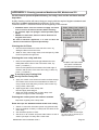
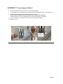
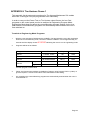
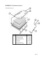
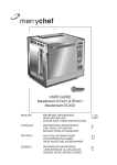
Mealstream 500
S E R V I C E
M A N U A L
Part No. 32Z3387 Issue No.3
For all Mealstream 501, 502 & 503 models manufactured
from January 2001 & Tim Hortons Models
SERVICE MANUAL
Merrychef
CAUTION MICROWAVE EMISSIONS
DO NOT BECOME EXPOSED TO EMISSIONS FROM THE MICROWAVE
GENERATOR OR PARTS CONDUCTING MICROWAVE ENERGY
Mealstream Ovens 32Z3387 Issue 3
Page 1
Table of Contents
Safety Code...........................................................................3
Product Specifications ...........................................................4
Installation Instructions ..........................................................5
Error Codes and Diagnostics.................................................6
Main Features........................................................................7
Electronic Controls ................................................................8
Manual Controls ....................................................................9
Power Output Testing to EN 60335-2-90 ............................10
Power Output Testing..........................................................11
Power Transformer Test......................................................11
High Voltage Capacitor Test................................................12
High Voltage Rectifier Test..................................................12
Magnetron Test ...................................................................12
Principal components LHS ..................................................13
Principal components RHS..................................................14
Principal components Top ...................................................15
Principal components Cavity Roof and Door.......................16
Principal components Cavity ...............................................17
Principal components ( not shown in main views ) .............18
Input wiring ..........................................................................19
Interlock Operation ..............................................................20
Electronic Control Panel Assembly .....................................21
Manual Controls Panel Assembly........................................22
Membrane Panel Circuit ......................................................23
Complete Spare Part Listing.......................................... 24-25
Electrical Diagrams ....................................................... 26-27
Appendix 1: MenuKey Download Procedure.......................28
Appendix 2: Cleaning procedure ................................... 29-30
Appendix 3: PCB Connection Points ............................. 31-33
Appendix 4: Transformer upgrade.......................................34
Appendix 5 Hot air motor replacement ......................... 35-39
Appendix 6: Temperature sensor replacement ...................40
Appendix 7: Fuse change FLM020 Type....................... 41-42
Appendix 8: Tim Hortons .............................................. 44-47
Appendix 9: Door interlock set-up procedure ................ 48-52
Manual corrections and modifications .................................53
Merrychef Limited,
Station Road West,
Ash Vale, Aldershot
Hampshire GU12 5XA
United Kingdom
Tel: +44 (0)1252 371000 Fax: +44 (0)1252 371007
Internet address: http://www.merrychef.com
E-mail: [email protected] or [email protected]
Mealstream Ovens 32Z3387 Issue 3
Page 2
SAFETY CODE
This manual is designed to assist engineers who have been on a recognised product familiarisation
and training course run by Merrychef Limited. It has been prepared to offer technical guidance for the
Merrychef Mealstream 501 range of Combination Microwave Ovens.
Please remember that it is wiser not to attempt a service task if you are unsure of being able to
complete it competently, quickly, and above all safely.
To avoid injury to yourself, and to protect the appliance from possible damage, please follow this
Safety Code when servicing these ovens.
Before attempting to repair the oven, check it for microwave leakage.
Check that the oven is not emitting microwaves, even when supposedly not in
operation.
Check that the oven is not operating continuously, whether the display indicates
cooking or not.
Always discharge the HT capacitors before working on the oven using a suitably
insulated 10 MΩ Resistor
Before removing the rear cover from the oven, ensure you do the following:
• Switch off the mains supply and remove the plug from the wall socket.
or
• If the oven is hard wired, ensure that the power is turned off at the isolator switch.
Note:
The On/Off switch on the oven is not adequate protection against electric
shock, as it does not isolate all of the internal wiring from the mains.
Upon completion of a service on a Mealstream oven, or before reconnecting the appliance to the
mains supply for testing, check all of the following points:
•
•
•
•
•
•
•
All internal electrical connections are correct (see wiring diagram Pages 26-27).
All wiring insulation is correct and is not touching a sharp edge.
All Earth connections are electrically and mechanically secure.
All door safety interlocks are secure and mechanically sound.
The door operation is smooth, and the arms run freely in the slots.
The door activates all three of the door interlock switches in the correct order.
The temperature sensor is correctly connected to the Power PCB.
Before finishing the service call, recheck the following points:
•
•
•
•
•
All of the electronics are functioning correctly, and all of the touch pads are working.
The power output of the oven is correct.
Microwave emission is below permissible limit - 5 mW/cm² (see BS EN 60335-2-90).
Oven has correct 50mm air gap all round and 50mm above.
Air flow should not be restricted.
Clean air filters are in place.
Mealstream Ovens 32Z3387 Issue 3
Page 3
Product specifications:
Model Number:
CTMx v f c p MK C
Example CTM524505MK
Mealstream EC501, High speed fan
230-240V, 50Hz, Series 5 electronic controls & MenuKey
CTMx
Fan Speed
v
Voltage
f
c
Frequency Control Type
p
Phase
MK
MenuKey
C
Catalytic
Converter
CTM3 =
Low speed
CTM5 =
High speed
22 = 220-230V EU
24 = 230-240V UK
50 = 50 Hz
60 = 60 Hz
2 = 2 phase
MK =
MenuKey
fitted
C=
EC503
Catalytic
Converter
5 = Electronic
CD2 = Rotary Dial
Controls
1 = 1 phase
Omitted
Power
Requirements
Refer to rating Plate
Power Output:
CTM3
Microwave 100%
Convection
Combination
Convection
Combination
1425W (IEC 705)
2500W
1425W + 2500W
3000W
1425W + 3000W
External
Dimensions
Height
Width
Depth
640mm (Plus 50mm minimum clearance above)
710mm (Plus 50mm minimum clearance each side)
630mm (Plus 50mm clearance behind)
Internal
Dimensions
Height
Width
Depth
Capacity
260mm
490mm
360mm
45.86 litres (1.62 ft³)
Weight
Nett
Gross packed
90kg
106kg
Construction
Cavity
Casework
304 Stainless Steel
Settings
Microwave
Temperature
Timer
100%,75%,50%,25%, Convection only
Off, 150°C, 175°C, 200°C, 225°C, 250°C
Up to 30 minutes
Up to 3 cooking stages of up to 30 minutes each
Programmed (Series 5)
CTM5
Mealstream Ovens 32Z3387 Issue 3
Page 4
Installation instructions:
Installation Instructions for Mealstream 500 series Combination Ovens
Power Supply Requirements
The Mealstream 500 series oven should be connected to a suitable electricity supply, which
can cope with the switching-on surge that occurs with certain types of catering equipment, such
as microwaves. Because of this requirement, we strongly recommend that a separate, suitably
rated supply is installed for the oven.
The supply for the oven should be fitted with a Type "C" circuit breaker, rated at:
30 Amp for Mealstream 500 Series (all models)
If the oven is hard-wired to the supply, a double-pole isolator switch with a contact gap of at
least 3mm should be fitted and positioned close to the oven to allow the oven to be moved for
servicing.
Positioning the Oven
In order to maintain adequate ventilation for air intake and exhaust, and to allow access for
cleaning filters, you must allow a minimum of 50mm clearance at the sides and rear of the
oven, and at least 50mm above. Air intake temperature should not exceed 35°C - excessive
temperature will lead to reduced operating duty cycle or premature ageing of internal
components.
Failure to comply with these conditions will invalidate the warranty.
NEVER
Install an oven above fryers, grills, griddles or any other major heat source.
NEVER
Stack machines on top of each other - always use a double stand.
ALWAYS
Place containers in the cavity carefully - impact damage may chip the
vitreous enamel coating on the runners and baffle plate.
50mm
50mm
50mm
Mealstream Ovens 32Z3387 Issue 3
50mm
350mm
Page 5
Error codes and diagnostics
Models with electronic controls identify some of the most common problems by flashing an
error message code in the time display window.
Error Message
Possible Cause
Service
1
Door not fully shut
Close door fully
2
Possible electrical fault
Check Microswitch Door Circuit
Check Microswitch Connection to PCB
Check Ribbon Cable
Check Relay PCB & Logic PCB
1
2
3
4
No time has been set
Invalid time has been set
Invalid program has been set
Number pad failure
5
Memory Failure running a
Program
Set a time
Set a valid time
Use call-back to check program
(MenuKey: no key downloaded)
Membrane key short circuit
Re-Program Pad,
if fault repeats replace Logic PCB
1
Oven not heating up
Check heater fuse
2
Possible Heater circuit fault
Confirm operation of heater, overheat
stat and heater circuit
1
Oven Cavity overheating
Check cavity sensor
Confirm heater relay is operating
1
Oven is not at correct
temperature to start program
Operator Error !!
Allow oven to reach correct
Programmed temperature
1
Oven control area is
overheating.
Check air filters
Check axial fan
Check installation for hot air intake
MenuKey removed before the Switch oven off and begin the MenuKey
download is complete
download again.
or the process has been
interrupted.
Mealstream Ovens 32Z3387 Issue 3
Page 6
Main features:
l
a
g
b
b
c
f
m
d
j
back panel
e
k
k
i
h
a On/Off SWITCH
This is used to turn the oven On or Off.
IT DOES NOT ISOLATE INTERNAL WIRING
FROM THE MAINS SUPPLY.
b HOT AIR VENTS
Allows steam and excess pressure to escape
from the oven cavity. It must be kept clear.
c OVEN CAVITY
The oven cavity is mainly constructed from
stainless steel panels. It must be kept clean.
d BAFFLE PLATE
EC501 Models:
The convection fan draws air over the heating
element into the cavity over the edges of the rear
baffle plate producing perfect heat distribution for
combination cooking. The metal grill covering the
fan must be kept clean and free of debris.
502 & 503 Models:
The convection fan, which is located behind the
cavity filter pulls air in through the catalytic
converter which removes the majority of the smoke
from the air flow.
e RUNNERS
These are mounted on each side of the oven
cavity to support the rectangular racks or oven
trays and are for use in Convection mode
only.
Mealstream Ovens 32Z3387 Issue 3
f HOT AIR FAN
Situated behind the baffle plate, and circulates
the hot air through the baffle plate, over the
heating element, and around the edge of the
baffle plate back into the cavity.
CTM3_ Low speed Fan
CTM5_ High Speed Fan
g RATING PLATE
The rating plate is situated on the rear of the
oven, and states the Model, Serial Number,
Electrical Ratings and Manufacturers telephone
number.
h DOOR
The door consists of a thermally insulated inner
section, and an additional air gap provided by a
twin skinned door front to lower the surface
temperature.
It is important that the choke plate and the slots
are free from debris.
i DOOR SEAL
j MAINS LEAD
k AIR FILTERS
Main intake for cooling air for internal
components. Must be clear of obstructions.
l MenuKey
m STEAM OUTLET
Page 7
Electronic controls:
j
i
b
a
g
h
a
Stage LED's
b
Program & Time Display
c
Service Indicator
d
Air Filter Block Indicator
e
Convection Pad
f
Power Pads
g
Time / Program Number Pads
h
Temperature Set Pads
i
Cancel / Callback Pad
j
Program Pad
k
MenuKey socket
Mealstream Ovens 32Z3387 Issue 3
f
c
e
d
k
Page 8
Manual controls:
a
b
c
TEMP °C
POWER %
d
TIME
merrychef
e
f
START
Mealstream CD
2
g
a
Power Neon ( Amber )
b
Temperature Control
c
Power Control
d
Timer
e
Start Push button
f
Cook cycle Neon ( Red )
g
Heater Neon ( Amber )
Mealstream Ovens 32Z3387 Issue 3
Page 9
Procedure A - Power Output Test in accordance with
BS EN 60335-2-90 Annex AA
This test is given in the BSI test standard for microwave ovens. It is reproduced below - not so that
you can follow it, but to show you why it is impractical in normal conditions. A simplified procedure,
which gives a good approximation to the BSI power output, is given in Procedure B which follows.
Note: This test can only be carried out on a COLD oven. If the oven has been operating, even for
only a few seconds, the power given will be lower than the oven rating. This test must also be carried
out at a stable voltage - the voltage in most kitchens varies considerably even within the period of the
test. If the oven has been operating, go to Procedure B.
You will need:
A thermometer capable of reading to ±0.1°C.
A cylindrical borosilicate glass container, 190 mm diameter, with a wall thickness of
3 mm or less.
A calculator.
A set of scales capable of reading 1kg to an accuracy of ± 1g.
A glass or plastic stirrer.
A jug capable of holding over 1 litre of water.
Drinkable water which is at a temperature of 10°C ± 1°C.
A “Variac” or similar variable transformer capable of supplying the oven to ensure a
stable voltage.
WARNING: The Borosilicate Glass container has thin walls and is therefore fragile
- take care not to break it during use.
Method
A cylindrical container of borosilicate glass is used for the test. It has a maximum thickness of
3mm, an external diameter of approximately 190mm and a height of approximately 90mm. The
mass of the container is determined.
At the start of the test, the oven and the empty container are at ambient temperature. Potable water
having an initial temperature of 10°C ± 1°C is used for the test. The temperature of the water is
measured immediately before it is poured into the container.
A quantity of 1000g ± 5g of water is added to the container and its actual mass obtained. The
container is then immediately placed in the middle of the oven base. The appliance is supplied at
rated voltage and operated at the maximum power setting. The time for the water temperature to
attain 20°C ± 2°C is measured. The oven is then switched off and the final water temperature is
measured within 60seconds.
NOTES:
1 The water is stirred before its temperature is measured.
2 Stirring and measuring devices are to have a low heat capacity.
The microwave power output is calculated from the formula:
4.187 MW (T2-T1) + 0.55 MC (T2-T0)
P=
t
where
P
MW
MC
T0
T1
T2
t
is the microwave power output, in watts;
is the mass of the water, in grams;
is the mass of the container, in grams;
is the ambient temperature, in °C;
is the initial temperature of the water, in °C;
is the final temperature of the water, in °C;
is the heating time in seconds, excluding the magnetron filament heat-up time.
Mealstream Ovens 32Z3387 Issue 3
Page 10
Procedure B - Simplified Power Output Test
You will need:
A thermometer capable of reading to ±0.1°C.
A Polypropylene tray approximately 200 mm x 200 mm.
A measuring jug.
A calculator.
Water which is at a temperature of 10°C ± 2°C.
1
2
3
4
5
6
7
8
For Tim Hortons
see APPENDIX 8
Measure 1 litre of cold water into the tray using the measuring jug.
Measure the water temperature, and record it as T[s].
Place the tray in the oven and close the door.
Turn the oven on.
Set the timer to 1:02. ( For Manual controls use a stopwatch set to 1 minute 2 seconds )
Press the “100%” power pad.
When the oven bleeps, open the door and remove the tray.
Stir the water thoroughly, and measure its temperature. Record this as T[e].
Calculation:
1
2
T[r] = T[e] - T[s].
Power = 70 x T[r]. Power is in Watts.
The power given by the above test should be within ±10% of the rated power.
Procedure C - Power Transformer Test
You will need:
A Digital Multi-meter (D.M.M.)
A Megger or similar resistance meter using 500V d.c.
1 Isolate the oven from the mains supply.
WARNING: High voltages and large currents are present at the secondary winding and filament
winding of the Power Transformer. It is very dangerous to work near this part when the
oven is on. NEVER make any voltage measurements at the High Voltage circuits,
including the magnetron filament.
WARNING: Even when the oven is not cooking, the Power Transformer has High Voltages present
because of the Soft Start circuit. Isolate the oven before testing.
2
3
4
Ensure that the High Voltage Capacitor is discharged before commencing work.
Remove all connections from the Power Transformer.
Using a D.M.M., check the continuity of the windings. Results should be as follows:
a
Mains winding between tags
Approx. 1.3 Ω
b
High Voltage winding
Approx. 82 Ω
c
Filament winding
between terminals
Less than 1 Ω
5
Using a Megger, test the insulation resistance between:
Primary winding and chassis
Pass if over 10 MΩ
Filament winding and chassis
Pass if over 10 MΩ
c
b
a
One end of the High Voltage winding is connected to the
chassis, so this is not tested.
Mealstream Ovens 32Z3387 Issue 3
Page 11
Procedure D - High Voltage Capacitor Test
You will need:
A Digital Multi-meter (D.M.M.)
A Megger or similar resistance meter using 500V d.c.
WARNING: High voltages and large currents are present at the High Voltage Capacitor. It is very
dangerous to work near this part when the oven is on. NEVER make any voltage
measurements at the High Voltage circuits, including the magnetron filament .
WARNING: Even when the oven is not cooking, the High Voltage Capacitor has High Voltages
present because of the Soft Start circuit. Isolate the oven before testing.
1. Isolate the oven from the mains supply.
2. Ensure that the High Voltage Capacitor is discharged before
commencing work.
3. Remove all connections from the High Voltage Capacitor.
4. Using a D.M.M., check for continuity between the terminals &
Between Terminals
Pass if approximately 10 MΩ
Between Terminals and Case
Pass if open circuit
5. Using a Megger, test the insulation resistance between the
terminals and the case.
Between Terminals and Case
Pass if over 100 MΩ
Procedure E - High Voltage Rectifier Test
You will need:
A Megger or similar resistance meter using 500V d.c.
WARNING: High voltages and large currents are present at the High Voltage Rectifier. It is very
dangerous to work near this part when the oven is on. NEVER make any voltage
measurements at the High Voltage circuits, including the magnetron filament .
WARNING: Even when the oven is not cooking, the High Voltage Rectifier has High Voltages
present because of the Soft Start circuit. Isolate the oven before testing.
1. Isolate the oven from the mains supply.
2. Ensure that the High Voltage Capacitor is
discharged before commencing work.
3. Remove all connections from the High Voltage
Rectifier.
4. Using the Megger, test for continuity in both
directions. Compare results with the table.
Open Circuit both ways
FAIL
Conducts one way only
PASS
Short Circuit both ways
FAIL
Conducts one way, leaks the other
FAIL
Procedure F - Magnetron Test
You will need:
A Megger or similar resistance meter using 500V d.c.
A Magnetron can be tested for an open filament or a short circuit
by carrying out a continuity check.
1. Isolate the oven from the mains supply.
2. Ensure that the High Voltage Capacitor is discharged before
commencing work.
3. Remove all connections from the Magnetron.
4. A continuity check across the Filament terminals should be 1ohm or less
5. A continuity check between each filament terminal and the
metal outer should read open.
Mealstream Ovens 32Z3387 Issue 3
Page 12
Principle components:
Left side
1
1A
2
2A
3
3A
4
4A
14
13
12
6
11
7
10
8
9
No
Description
EC 501/2/3
RD 501
1
Fuse holder
30Z0231
30Z0231
1A
Fuse 10 amp
30Z0217
30Z0217
2
Fuse holder
30Z0231
30Z0231
2A
Fuse 10 amp
30Z0217
30Z0217
3
Fuse holder
30Z0231
30Z0231
3A
Fuse 1 amp
30Z0957
30Z0957
B
4
Fuse holder 30amp ( FLM Series )
30Z1178
30Z1178
4A
Fuse 20 amp Littlefuse FLM020B
30Z1177
30Z1177
6
Mains terminal block
31Z0149
31Z0149
7
Filter ( Heater circuit )
30Z0997
30Z0997
8
Filter ( Microwave circuit )
30Z0997
30Z0997
9
Door spring short
520000
520000
9
Door spring long
40C1141
40C1141
10
Door arm stop assembly
11C0279
11C0279
11
Microswitch ( Primary )
30Z0240
30Z0240
12
Door hinge assembly ( LH )A
11C0167
11C0167
13
Door arm assembly
11C0300
11C0300
14
Microswitch ( Monitor )
30Z0240
30Z0240
Note A: see page 17 for parts
Note B: see appendix for models before March 2004
Mealstream Ovens 32Z3387 Issue 3
Page 13
Principle components:
Right side
22
21
13
20
16
No
17
10
9
Description
EC 501/2/3
RD 501
520000
520000
Door spring long
40C1141
40C1141
10
Door arm stop assembly
11C0279
11C0279
13
Door arm assembly
11C0300
11C0300
9
Door spring short
9
A
16
Door hinge assembly ( RH )
11C0166
11C0166
17
Microswitch ( Secondary )
30Z0240
30Z0240
20
Steam pipe
790046
790046
21
Steam vent guard
790061
790061
22
Temperature sensorC
50E123
50E123
Note A: see page 17 for parts
Note C: see appendix for models before March 2004
Mealstream Ovens 32Z3387 Issue 3
Page 14
Principle components:
Top view
60
61
23
23
24
24
25
25
26
26
27
27
28
No
Description
EC 501/2/3
62
RD 501
23
Magnetron
30Z0264
30Z0264
24
Resistor Gold 470 R
30Z0283
30Z0283
25
HT diode
11C0266
11C0266
26
Capacitor 1.1µF
30Z1077
30Z1077
27
Transformer 220V 50Hz
30Z0083
30Z0083
27
Transformer 240V 50Hz
30Z1018
30Z1018
28
Twin blower motor
310110
310110
60
25mm OD Flexible conduit
314402
314402
61
20mm OD Flexible conduit
314401
314401
62
Capacitor clip
31Z0175
31Z0175
Mealstream Ovens 32Z3387 Issue 3
Page 15
Principle components:
Door & cavity roof
67
67a
72
71
Note: for Tim Hortons see Appendix 8
No
67
67a
Description
EC 501/2/3
Stirrer glass & long seals
Stirrer glass short side seal
71
Door seal kit
72
Door choke
RD 501
40C0954
40C0954
790052
790052
11C0292
11C0292
790007
790007
Air Filters
81
81
No
81
Description
Air filter panel (removable)
Mealstream Ovens 32Z3387 Issue 3
EC 501/2/3
40C0868
RD 501
40C0868
Page 16
Principle components:
Heater Element, Catalytic Converter & Cavity parts:
CTM5_, [EC501]
78
69
76
74
77
68a
CTM5_, [EC502]
70
78
79
77
74
68a
77
76
CTM5_, [EC503]
77
78
80
76
74
77
68a
CTM3_
[EC501, RD501]
68
69
74
77
No
Description
Part No.
68
Heater element (2.5kW)
40C0954
68a
Heater element (3.0kW)
40C0948
69
Heater element cover plate
70
Baffle
11C0311
76
Dome Nut
80X7025
77
Shelf Support
40C0950
78
Hot Air Impeller
79
Element cover plate Assembly
11C0474
80
Element cover plate Assembly
11C0467
Mealstream Ovens 32Z3387 Issue 3
790047
MC3703B
Page 17
Principle components: ( not shown in main views )
12
Left Hand Door Hinge
Assembly
16
Right Hand Door Hinge
Assembly
(Includes all parts shown)
(Includes all parts shown)
52
52
51
54
51
55
53
55
54
53
58
57
57
Hot air motor:
Low Speed
Stirrer motor assembly
Hot air motor:
High Speed
50
Motor shaft screen
and seal assembly
49
No.
Description
EC501/2/3
RD501
12
Door Hinge Assembly LH
11C0167
11C0167
16
Door Hinge Assembly RH
11C0166
11C0166
49
Motor shaft screen
40C1005
40C1005
50
Hot air motor damper/seal
40C1008
40C1008
51
Pin
790027
790027
52
Roller
40C0752
40C0752
53
M5 Hex/hd s/s Screw
101825
101825
54
M5 stainless steel Nut
80X7003
80X7003
55
LH Hinge bracket
790024
790024
56
RH Hinge bracket
790025
790025
57
Hot air motor Low Speed [CTM3]
11C0161
11C0161
57
Hot air motor High Speed [CTM5]
11C0526
58
Stirrer motor assembly
11C0162
Mealstream Ovens 32Z3387 Issue 3
—–
11C0162
Page 18
Input wiring details
Green/Yellow
6
Blue
Brown
48
46
47
Description
Part No.
6
Mains Terminal Block
31Z0149
46
Cable Gland
31Z1070
47
Gland Nut
31Z1082
48
Mains Cable 3 Core
31Z0148
No
High Speed Hot Air Motor [CTM5] connections and wiring
Mealstream Ovens 32Z3387 Issue 3
Page 19
Door interlock operation
The door on the oven is monitored by three microswitches. These are used in the
conventional “Primary, Secondary and Monitor” switch arrangement shown below.
The switches operate as follows:
Door Interlock Arrangement
Secondary switch
L
17
Primary switch 11
Power Out
Power In
Monitor switch 14
N
The diagram shows the microswitches in door closed position
1. Primary Interlock [ 11 , Bottom left-hand ] and
Secondary Interlock [ 17 , Bottom right-hand ] Switches.
Operate simultaneously.
The Primary switch or Secondary switch will cut off the microwave emissions
from the oven when the door is opened by breaking the mains supply circuit to
the transformers.
2. Monitor [ 14 ,Top left-hand Side ]
The Monitor switch will produce a short circuit across the mains supply if the
Primary interlock switch is faulty, thus blowing the microwave fuse and rendering
the oven inoperative.
The Secondary interlock switch will cut off the microwave emission if the other
switches have failed.
Note:
If operation of the Monitor switch has caused the Microwave Fuse to blow, the
Primary and Monitor microswitches must be changed, as they may have been
damaged by the high short-circuit currents involved.
Mealstream Ovens 32Z3387 Issue 3
Page 20
Electronic control panel assembly: EC501, EC502 & EC503
34
29
33
32
31
73
30
No
Description
Part No.
29
On/Off Switch
30Z0503
30
Control Panel Assembly (without MenuKey)
11C0294
30
Control Panel Assy with MenuKey
11C0438
30
Locare Control Panel Assy with MenuKey
11C0458
31
Logic Board (without MenuKey)
11C0291
31
Logic Board with MenuKey
11C0377
32
Relay Board
11C0212
33
AC Ribbon connector
11M0116
34
DC Ribbon connector
11M0117
73
MenuKey Assembly
10C0148
Mealstream Ovens 32Z3387 Issue 3
Page 21
Manual control panel assembly: RD501
38
39
40
40
35
29
38
44
34
41
33
29
38
44
45
41
38
No
Description
Part No.
29
On /off switch
30Z0503
33
ac voltage connector 6 way
11M0116
34
dc voltage connector 10 way
11M0117
35
PCB Assembly
11C0295
38
Red Neon
39
Timer
30Z0991
40
Potentiometer 5k
40C0892
41
Amber Neon
43
Panel assembly
11C0307
44
Pushbutton
31Z0349
45
Control knob Red/Grey
11C0173
45
Control knob Blue
11C0406
Mealstream Ovens 32Z3387 Issue 3
316030
316031
Page 22
Membrane panel circuit
You will need:
A Digital Multi-meter (D.M.M.)
1.
2.
3.
4.
Isolate the oven from the mains supply.
Remove the Logic Assembly from the Control Panel Housing.
Unplug the membrane “tail” from the Logic PCB Assy.
Using a D.M.M., check for continuity between the correct terminals when the
pads are pressed.
5. When the panel has been tested, re-assemble and re-test the control housing.
1
Mealstream Ovens 32Z3387 Issue 3
10
Page 23
Part number identification chart:
No
Description
EC501/2/3
RD501
1
Fuse holder
30Z0231
30Z0231
1a
Fuse 10 amp
30Z0217
30Z0217
2
Fuse holder
30Z0231
30Z0231
2a
Fuse 10 amp
30Z0217
30Z0217
3
Fuse holder
30Z0231
30Z0231
3a
Fuse 1 amp
30Z0957
30Z0957
4
Fuse holder 30amp ( FLM Series )
B
B
30Z1178
30Z1178
30Z1177
30Z1177
4A
Fuse 20 amp Littlefuse FLM020
6
Mains terminal block
31Z0149
31Z0149
7
Filter ( Microwave circuit )
30Z0997
30Z0997
8
Filter ( Heater circuit )
30Z0997
30Z0997
9
Door spring short
520000
520000
9
Door spring long
40C1141
40C1141
10
Door arm stop assembly
11C0279
11C0279
11
Microswitch ( Primary )
30Z0240
30Z0240
12
Door hinge assembly ( LH )
11C0167
11C0167
13
Door arm assembly
11C0300
11C0300
14
Microswitch ( Monitor )
30Z0240
30Z0240
16
Door hinge assembly ( RH )
11C0166
11C0166
17
Microswitch ( Secondary )
30Z0240
30Z0240
20
Steam pipe
790046
790046
21
Steam vent guard
790061
790061
50E123
50E123
C
22
Temperature sensor
23
Magnetron
30Z0264
30Z0264
24
Resistor Gold 470 R
30Z0283
30Z0283
25
HT diode
11C0266
11C0266
26
Capacitor 1.1 µF 50Hz
30Z1077
30Z1077
26
Capacitor 0.88µF 60Hz
30Z1075
30Z1075
27
Transformer 220V 50Hz
30Z1018
30Z1018
27
Transformer 240V 50Hz
30Z1183
30Z1183
27
Transformer 220V 60Hz
30Z1192
30Z1192
27
Transformer 240V 60Hz
30Z1191
30Z1191
28
Twin blower motor
310110
310110
29
On/Off Switch
30Z0503
30Z0503
30
Control Panel Assembly (without
Menukey)
11C0294
———
30
Control Panel Assy with Menukey
11C0438
———
30
Locare Control Panel Assy with
Menukey
11C0458
———
31
Logic Board (without Menukey)
11C0291
———
31
Logic Board with Menukey
11C0377
———
32
Relay Board
11C0212
———
33
AC Ribbon connector 6 way
11M0116
11M0116
34
DC Ribbon connector 10 way
11M0117
11M0117
Mealstream Ovens 32Z3387 Issue 3
Note B: see APPENDIX 7
for models before March 2004
Note C: see APPENDIX 6
for models before March 2004
Page 24
Part number identification chart:
No
Description
EC501/2/3
RD501
35
PCB Assembly
———
38
Red Neon
———
316030
39
Timer
———
30Z0991
40
Potentiometer 5k
———
40C0892
41
Amber Neon
———
316031
43
Panel assembly
———
11C0307
44
Pushbutton
———
31Z0349
45
Control knob Red/Grey
———
11C0173
45
Control knob Blue
———
11C0406
46
Cable Gland
31Z1070
31Z1070
47
Gland Nut
31Z1082
31Z1082
48
Mains Cable 3 Core
31Z0148
31Z0148
49
Motor shaft screen
40C1005
40C1005
50
Hot air motor damper/seal
40C1008
40C1008
51
Pin
790027
790027
52
Roller
40C0752
40C0752
53
Bolt
101825
101825
54
Nut
80X7003
80X7003
55
LH Hinge bracket
790024
790024
56
RH Hinge bracket
790025
790025
57
Hot air motor Low Speed [CTM3]
11C0161
11C0161
57
Hot air motor High Speed [CTM5]
11C0526
——
58
Stirrer motor assembly
11C0162
11C0162
60
25mm OD Flexible conduit
314402
314402
61
20mm OD Flexible conduit
314401
314401
62
Capacitor clip
31Z0175
31Z0175
67
Stirrer glass
40C0954
40C0954
67a
Stirrer glass short side seal
790052
790052
68
Heater element 2.5kW
——
790063
68a
Heater element 3.0kW
40C0948
——
69
Baffle Plate
790047
790047
70
Baffle Side ( 2 No. )
11C0311
11C0311
71
Door seal kit
11C0292
11C0292
72
Door choke
790007
790007
73
MenuKey Assembly
10C0148
——
74
Mesh washer RFI gasket
31Z5044
31Z5044
75
Shelf support
40C0864
40C0864
76
Dome Nut
80X7025
80X7025
77
Shelf Support
40C0950
40C0950
78
Hot Air Impeller
MC3703B
MC3703B
79
Element cover plate Assembly
11C0474
11C0474
80
Element cover plate Assembly
11C0467
11C0467
81
Air filter panel (removable)
40C0868
40C0868
82
PCB stand off
2243033
2243033
Mealstream Ovens 32Z3387 Issue 3
11C0295
Page 25
Circuit diagram: EC501, EC502, EC503
Mealstream Ovens 32Z3387 Issue 3
Page 26
Circuit diagram: RD501, CTM3__CD2
Mealstream Ovens 32Z3387 Issue 3
Page 27
APPENDIX 1: MenuKey Download Procedure
The MenuKey™ System automatically changes all the cooking
programs on the numbered icon pads with the turn of a key.
To change the menus on the oven:
1
Ensure the power switch is off.
2
Lift the MenuKey cover in the
front panel of the oven and
put the key in the keyhole
Turn the key clockwise to the
stop ( ¼ turn ).
Do not remove the key at this
stage.
3
Switch the power switch on.
The oven will now go through the
program download sequence by
displaying the following:
The Key Code
example: Key C02
The number of programs and each
program number on the key.
example: 27 Programs
EPS - FAIL - REDO
External Program
System ERROR.
If the key is removed
before the download is
complete or the process is
interrupted the display
shows “EPS” then “FAIL”
then “REDO”. Switch the
oven off and begin the
MenuKey download again.
When the display shows 00:00.
Remove the key and close the cover.
The oven is now ready to use with the
new programs.
To confirm the download is successful
Switch off the oven.
Switch on and the display briefly will show the following:
1. The new key code
2. 00:00 (oven ready to use)
If the download is not successful the key number will not be
displayed and if the program pads are pressed an E3 error will
display.
Mealstream Ovens 32Z3387 Issue 3
Page 28
APPENDIX 2: Cleaning procedure Mealstream 501
For the oven to operate at peak efficiency, the cavity, door and the air filters must be
kept clean.
A daily cleaning routine will ensure that you comply with the required hygiene standards
and will help to maintain and prolong the efficiency of your oven.
Follow the SAFETY INSTRUCTIONS at the beginning of this manual.
• ALWAYS switch off at the electrical supply and allow
oven to cool for at least 20 minutes before cleaning.
Faults arising from neglect
or misuse including use
without clean filters in place
are not covered by the
guarantee. Service visits as
a result of such faults will be
chargeable.
• As required, wipe out spillage's with disposable paper
wipes
• NEVER use steel wool, knives or harsh abrasives on
any part of the oven
As with all electrical appliances, it is wise to have the
electrical connections inspected periodically.
Cleaning the Air Filters
1
2
Remove the air filters from each side of the oven by
sliding the filter out from the front.
Wash in clean, warm soapy water, rinse and pat dry. Slide
back into position through slots.
Cleaning the oven cavity and door
1
2
3
4
Remove food particles from the gap between the rear
baffle plate and the floor of the oven with a clean, dry
brush. ( Location A )
Remove food particles from between the inside edge of
the door and the front of the oven floor using a clean, dry
brush. ( Location B )
Apply non-caustic oven cleaner to interior surfaces
except door seals. Leave for the recommended time.
Wash off using a clean cloth and plenty of clean, warm
water. Dry using a fresh, clean cloth.
Wipe hinges with a clean, damp cloth.
DO NOT apply lubricating oil.
Wipe door seals carefully with a clean damp cloth.
Examine for signs of wear or damage.
DO NOT USE THE OVEN
WITHOUT CLEAN AIR
FILTERS IN POSITION
B
A
Door Seal
Cleaning the control panel and exterior surfaces
Wipe down regularly with a damp cloth.
If the door seals are damaged,
the oven must be repaired by an
approved Servicer.
Hints and Tips for stubborn stains in the oven cavity
1
2
3
4
Switch on oven with microwave power only (without heat).
Place a container of water (1.5 litres) into the centre of the
oven cavity.
Set microwave power to 100%.
Set timer to 30 minutes and press start button at end of
steam cycle wipe out cavity with a clean cloth.
Mealstream Ovens 32Z3387 Issue 3
Page 29
APPENDIX 2: Cleaning procedure Mealstream 502, Mealstream 503
For the oven to operate at peak efficiency, the cavity, door and the air filters must be
kept clean.
A daily cleaning routine will ensure that you comply with the required hygiene standards and
will help to maintain and prolong the efficiency of your oven.
Follow the SAFETY INSTRUCTIONS at the beginning of this manual.
• ALWAYS switch off at the electrical supply and allow
oven to cool for at least 20 minutes before cleaning.
• As required, wipe out spillage's with disposable paper
wipes
• NEVER use steel wool, knives or harsh abrasives on
any part of the oven
Faults arising from neglect
or misuse including use
without clean filters in place
are not covered by the
guarantee. Service visits as
a result of such faults will be
chargeable.
As with all electrical appliances, it is wise to have the
electrical connections inspected periodically.
Cleaning the Air Filters
1
2
Remove the air filters from each side of the oven by
sliding the filter out from the front.
Wash in clean, warm soapy water, rinse and pat dry. Slide
back into position through slots.
Cleaning the oven cavity and door
1
Remove food particles from the gap between the rear
baffle plate and the floor of the oven with a clean, dry
brush. ( Location A )
Remove food particles from between the inside edge of
the door and the front of the oven floor using a clean, dry
brush. ( Location B )
DO NOT USE THE OVEN
WITHOUT CLEAN AIR
FILTERS IN POSITION
Do not spray any cleaning fluid
directly into the cavity filter
2
3
4
Apply non-caustic oven cleaner to interior surfaces except
door seals. Leave for the recommended time. Wash off
using a clean cloth and plenty of clean, warm water. Dry
using a fresh, clean cloth.
Wipe hinges with a clean, damp cloth.
DO NOT apply lubricating oil.
Wipe door seals carefully with a clean damp cloth.
Examine for signs of wear or damage.
A
Door Seal
B
Cleaning the control panel and exterior surfaces
Wipe down regularly with a damp cloth.
Hints and Tips for stubborn stains in the oven cavity
1
2
3
4
Switch on oven with microwave power only (without heat).
Place a container of water (1.5 litres) into the centre of the
oven cavity.
Set microwave power to 100%.
Set timer to 30 minutes and press start button at end of
steam cycle wipe out cavity with a clean cloth.
Mealstream Ovens 32Z3387 Issue 3
If the door seals are damaged,
the oven must be repaired by an
approved Servicer.
Page 30
APPENDIX 3: PCB Connection Points and key features, EC501, EC502 & EC503
11C0291 Issue 5
Cavity sensor
50E123
Relay PCB
Relay PCB
°C Link
Mealstream Ovens 32Z3387 Issue 3
Page 31
APPENDIX 3: PCB Connection Points and key features EC501, EC502 & EC503
11C0377 Issue 2
Menukey
Temperature
Calibration
Relay PCB
Relay PCB
°C Link
Mealstream Ovens 32Z3387 Issue 3
Page 32
APPENDIX 3: PCB Connection Points and key features EC501, EC502 & EC503
11C0212 Issue 11
Relay PCB
Logic PCB
Transformer 1 (LHS)
Transformer 2 (RHS)
Soft start common relay
Heater switch
Return from door switch & 0H Mag stats
Logic PCB
Neutral
Live
Earth
Mealstream Ovens 32Z3387 Issue 3
Page 33
APPENDIX 4: Transformer Upgrade
In partnership with our supplier Tabuchi, we have developed a multi-tap transformer that will
output 208V, 220V & 240V. There are 2 models for 50Hz and 60Hz power supply.
Should you need to change a transformer to any Mealstream 501 product, you should use the
new 30Z1233 ( 50Hz power supply ) or 30Z1230 ( 60Hz power supply) multi-tap transformer, see
matrix below.
Should you have an oven where just one transformer has failed, you can mix an old transformer
with a new transformer on the oven.
Note: The capacitor values remain the same when using the new 30Z1233 or 30Z1230 transformer.
Replacement Transformer Matrix
Voltage
Frequency
Part No.
220V
240V
50Hz
30Z1233
60Hz
30Z1230
208V
220V
240V
Transformer 30Z1230 shown for clarification
voltage
specific
Input
common
input
voltage
specific
Input
Page 34
APPENDIX 5: Hot air motor replacement procedure 1
we have improved the hot air motor assembly by enhancing the wave trap and balancing the
impeller which is now fitted by a grub screw to a flat on the shaft. The tolerances to manufacture
the motor shaft have also been tightened to improve the fit of the balanced impeller.
Parts required: 10C0192 service kit (consists of the following parts):
Part No.
Description
11C0472
501Hot air motor service kit
x1
40C1201
Hot air motor Wave Trap
x1
2747048
Motor spacer board
x1
101520
M4x10 Hex HD Screw
x4
31Z4016
M5 flange nut
x4
31Z5007
M5 steel spring washer
x4
31Z5008
M5 steel washer large
x4
Recommended tools:
RS Components Pt. No. 547-379
RS Components Pt. No. 769-002
Quantity
Quickset driver 1-6Nm with 0.1Nm increments
1/4” hex to 1/4” square converter 50mm long
Procedure for fitting new RF trap and Motor assembly
Step 1
Isolate oven from mains supply.
Step 2
Remove necessary covers to obtain access to the rear of the oven.
Step 3
Remove shelf supports.
Step 4
Remove element cover plate.
Step 5
Remove and discard impellor. (Item 1)
Step 6
Disconnect motor at terminal block.
(note where each wire is connected)
Step 7
Remove and discard hot air motor assembly. (Item 2)
Step 8
Remove and discard motor screen tube with seal. (Item 3)
(check cavity surface and clean if necessary)
(Item 1)
(Item 3)
(Item 2)
Parts to be removed
Page 35
APPENDIX 5: Hot air motor replacement procedure 2
Step 9
Fit new wave trap Pt. No. 40C1201 to cavity. See figures 1(a) & 1(b)
(Making sure it is centred in the hole)
Ensure wave trap is fitted correctly and not caught around the edge of the hole.
See figure 2
Figure 1(a)
Pt. No. 40C1201
Figure 2
Rear of cavity
Note: Ensure wave trap is fitted
correctly and not caught
around the edge of the hole.
Pt. No. 101520
Figure 1(b)
Pt. No. 40C1201
Page 36
APPENDIX 5: Hot air motor replacement procedure 3
Step 10
Fit new hot air motor assembly Pt. No. 11C0472 (see diagrams below)
Make sure the motor shaft is centred in the hole
A) Fit motor assembly Pt. No. 11C0472 and secure finger tight with flange nuts &
washers.
B) Push the alignment tool (40C1211) onto the motor shaft and ensure initial step of the
tool locates into the wave trap. See figures 3a & 3b (see alignment tool figure 8)
C) Whilst supporting the weight of the motor assembly in one hand, tighten up the
securing nuts to 3.5Nm. This should align the shaft to the centre of the wave trap.
See figure 4
D) Remove the alignment tool and check shaft is centrally located. See figure 5
Note: Should the motor shaft not be central to the wave trap, follow the adjustment instructions
on the next page.
Figure 3b
Figure 3a
Note:
Ensure
motor shaft
is centrally
located
through the
wave trap
hole.
Figure 5
Figure 4
Earth point on
bottom left
mounting stud.
Page 37
APPENDIX 5: Hot air motor replacement procedure 4
Adjusting alignment procedure
To ensure correct alignment of the assembly there
are 2 procedures that may be required:
Procedure 1
The 4 bolts holding the wave trap to the cavity need
to be loosened off sufficiently to allow movement of
the wave trap.
See figure 6 (see Alignment tool figure 8)
You must then slide the alignment tool onto the
motor shaft, keeping pressure on the rear of the tool
only and not applying any sideways pressure. At the
same time pushing on the bolts of the wave trap to
manipulate the trap into a position where the outer
diameter of the tool goes into the hole of the wave
trap.Once the tool is located, tighten up the 4 bolts
and remove the alignment tool.
Figure 6
Loosen x4
Allows wave trap to
move to allow
alignment tool to fit.
If procedure 1 is successful go to step 11
Procedure 2
With both wave trap and hot air motor secure, you
must then slide the alignment tool onto the motor
shaft, keeping pressure on the rear of the tool only
and not applying any sideways pressure until it
bottoms out on the cavity face. You must then push
sideways and forward on the tool to allow the initial
step of the tool to go into the wave trap, making note
of which direction you had to push the tool for when
aligning the motor.
See figures 7(a) & 7(b) (see tool figure 8)
With the alignment tool in position, you must then
loosen the 4 nuts holding the fibre board that the
motor is mounted to.This will allow you to push the
board not the motor in the same direction as they
pushed the tool. This will then bring the motor into
alignment with the wave trap.
Note: If you are looking into the cavity and had to
push the tool to the right, when looking at the motor
Loosen x4
Allows board to
be pushed to
allow alignment
tool to fit.
Figure 7a
PUSH
Figure 7b
Alignment tool 40C1211
PUSH
Figure 8
PUSH
INITIAL STEP
PUSH
Page 38
APPENDIX 5: Hot air motor replacement procedure 5
Step 11
With the alignment correct Reconnect motor wires at terminal block. See figure 9a & 9b
Step 12
Fit new impeller to motor shaft. See figure 10a & 10b
(ensure grub screw lines up with the flat on the shaft)
Fit the screw to the impeller and wind down until you feel it touch the motor shaft. Then
gently push and pull the impeller back and forth to verify that the screw has located in the
slot. Pull the screw to the front of the slot prior to securing.
Step 13
Refit element cover plate.
Step 14
Refit shelf supports.
Step 15
Test oven.
(Care should be taken when powering up ovens with covers removed)
(check motor is running freely and check emissions near new RF trap)
Step 16
Refit covers.
Earth point on
bottom left
mounting stud
Live from PCB CN 7
Via gold resistor for
240v & 220V Ovens
Neutral from
Blower motor
1
Motor start
Capacitor
6 uf
2
3
Brown
Blue
Hot air
motor
Blue
Brown
Black
Figure 9a
Figure 9b
Pull the screw
to the front of
the slot before
tightening the
screw down
push and pull
the impeller
back and forth
to verify that
the screw has
located in the
slot
Figure 10a
Figure 10b
Page 39
APPENDIX 6: Temperature Sensor replacement
Mealstream ovens manufactured before March 2004
If you are required to fit a new temperature sensor to a Mealstream 501 oven on a service call,
you need to follow the procedure below to verify that the sensor is holding firm in the pocket.
The diagram below shows the area of the thermistor causing the problem. This problem has been
eliminated by increasing the hole depth in the temperature sensor pocket thus allowing the
thermistor to goes further into the pocket and lock into position.
Procedure for checking the temperature sensor fit in the sensor pocket
1. Fit the temperature sensor Pt. No. 50E123 as normal with a slight twist to lock the sensor into
the pocket.
2. If the sensor you have does not lock into the pocket and comes out of the pocket with little or
no effort, you will need to replace the pocket with one that has been modified as shown.
Part No.
Description
Quantity
11C0301
Temperature sensor pocket assembly
1
50E123
Thermistor
1
swaged area to lock onto
Old pocket
The temperature
sensor pocket has
been modified to
accommodate the
longer
temperature
sensor.
16mm
swaged area to lock onto
New pocket
24mm
Page 40
APPENDIX 7: Fuse change (FLM20) 1
Mealstream ovens manufactured before March 2004
Brief description:
13A anti-surge fuses Pt. No. 30Z0168 are no longer manufactured these are now replaced with
FLM020 fuses Pt. No. 30Z1177 for the Microwave circuit on all Mealstream 501 ovens.
To replace a fuse on an oven manufactured before March 2004 and fitted with this fuse type it is
necessary to replace the fuses and fuse holders with FLM 020 type.
Part No.
Description
Quantity
30Z1177
20A littlefuse FLM020
2
30Z1178
30A fuse holder (FLM Series)
2
31Z2092
Label - 20A FLM fuse
1
31Z3116
6x1/2” self tap pan
2
Procedure for replacing 13A anti-surge Fuses with FLM020 type
1. Isolate oven from mains power
supply.
2. Remove necessary covers to obtain
access to the L/H inner side panel.
3. Remove the wires from the existing fuse holders and fit them
to the FLM20 fuse holders Pt. No. 30Z1178. (A)
4. Remove fuses and unscrew the existing fuse holders, discard
all parts.
5. Secure the new fuse holders into positions using No.6x1/2” self
tap screw Pt. No. 31Z3116 x2. The fuse holders are to be
locked together prior to fitting into the hole shown in the
diagram. (B)
A
B
A
Page 1 of 2
Page 41
APPENDIX 7: Fuse change (FLM20) 2
6. Push fit the new fuses Pt. No. 30Z1177 into the fuse holders.
7. Fit new label Pt. No. 31Z2092 over the existing label leaving the F5 and F1 still showing (C)
8. Power up the oven and check machine functions correctly.
(Care should be taken when powering up ovens with covers removed).
If fuse still blows, check microswitch setup is correct and replace if necessary.
9. Turn off the power and isolate the oven from the mains power supply.
10. Replace covers.
20A FUSE
C
FLM SERIES
MERRYCHEF PART
No. 30Z1177
Page 42
APPENDIX 8: Tim Hortons Ovens 1
This appendix list the parts and procedures for Tim Hortons Mealstream 501 models
which are a vend type oven pre-programmed from a MenuKey.
In order to carry out the Power Test on Tim Hortons variant Ovens, the Icon Pad
programs on the control panel need to be switched to Engineering Program Mode.
Engineering Mode does not affect the current Menukey program settings for the Icon
pads and the current Menukey programs are automatically restored when the oven is
next switched on.
To switch to Engineering Mode Programs:
1
With the oven switched off hold down the CANCEL Pad and switch the oven ON, the display
shows the current Menukey Code, continue to hold the CANCEL Pad for approximately 10
seconds until the display shows EE
2
00:00 indicating the oven is now in engineering mode
Programs will be set as follows:
Program Number
Time
Temp
Power
Pad 01
1 minute 3 secs
Off
100%
Pad 02
3 minutes
Off
100%
Pad 03
59 minutes 59secs
480 °F
None
30 minutes
480 °F
100%
29 minutes 59 secs
480 °F
50%
Stage 1
Pad 04
Stage 2
All other programs will be blank
3
Follow the Power test procedure as detailed on Page 24 using Program Pad 01 ( Cake) to
give the required 1 minute 3 seconds at 100% Microwave Power setting.
4
On completion the current Menukey programs are automatically restored when the oven is
next switched on.
Page 43
APPENDIX 8: Tim Hortons Ovens 2
PROCEDURE FOR POWER OUTPUT MEASUREMENT
The power output specification, 1425W on this model is established under IEC 705 standard
method. This method is only workable in Laboratory controlled conditions.
An approximate method is as follows:
To carry out this test the Icon Pads need to be switched to ENGINEERING MODE PROGRAMS
See previous page
1
Fill one beaker ( glass or plastic ) with one litre ( 1.78 pints ) of tap water
( at about 20ºC/68ºF ) and measure the water temperature.
( Use a thermometer with a 1/10, 0.1 degree gauge ).
2
Place the beaker in the centre of the cavity.
3
Tim Hortons Ovens only
With the oven in ENGINEERING MODE Press Pad 01 (Cake) and any Load Pad ( Quarter,
Half, Full ) Wait until the counter reaches zero.
4
Take the beaker out immediately stir the water with a plastic implement and measure the
water temperature.
5
Calculate the temperature rise of water in the beaker. The temperature rise of the water
should be within the following range:
Temperature Rise
15ºC ( 27ºF ) Minimum
20ºC ( 36ºF ) Maximum
Note:
Power Output is affected by the line voltage under load. For correct Power Output
measurement, the line voltage under load must be correct.
Page 44
APPENDIX 8: Tim Hortons Ovens 3
2
Door and cavity roof:
1
2
8
4
6
7
5
3
No
Description
Part No.
1
Stirrer glass assy. ( inc. long seals )
11C0319
2
Cavity roof seal (short)
790052
3
Door Handle Towel Rail
32Z1064
4
Bolt 1/4" 20 UNC 3/4" Hex
5
Door Handle
40C1020
6
Spring Washer
31Z5005
7
Flat Washer S/S M6 x 20
8
Door Assembly Tim Hortons
109050
104054
11C0380
Page 45
APPENDIX 8: Tim Hortons Ovens 4
Tim Horton special parts:
12
16
13
15
14
No
Description
Tim Hortons
Part No.
12
Wire Rack
40C1011
13
Crumb Tray
14
Shelf Support
Tim Hortons
10C0174
15
Shelf support fixing bolt
80T7133
16
Push fit bumper ( Rear Panel )
31Z1187
RBR290X02
Page 46
APPENDIX 8: Tim Hortons Ovens 5
Tim Hortons control panel
N
M
MENU
KEY
K
K Preheat
L
M
L Cancel
O
M Icon Cook Pads
N MenuKey™
O Quarter, Half
& Full Batch Load
For 240V model
No
Description
Part No.
30
Control Panel Assy with Menukey
11C0414
31
Logic Board
11C0411
32
Relay Board
11C0403
Mealstream 501 US Tim Hortons & Unbranded Variant
Note:PINS 1-4 Lower Layer & Pins 5-10 upper layer
Page 47
APPENDIX 9:
PROCEDURE FOR DOOR INTERLOCK ADJUSTMENT AND TEST (1)
The door on the Mealstream oven is monitored by three microswitches. These are used in the
conventional “Primary, Secondary and Monitor” switch arrangement shown below.
The switches operate as follows:
Door Interlock Arrangement
L1
Primary switch
Switches shown in Door Closed position
11
Secondary switch
Power Out
Power In
L2
17
Monitor switch 14
1. Monitor switch ( 14 ,Top left-hand Side ). The Monitor switch will produce
a short circuit across the mains supply if the Primary interlock switch is
faulty, when the door is opened, thus blowing the microwave fuse and
rendering the oven inoperative.
2. Primary Interlock ( 11 , Bottom left-hand ) and Secondary Interlock
( 17 , Bottom right-hand ) Switches. Operate simultaneously.
The Primary switch will cut off the microwave emissions from the oven when
the door is opened by breaking the electrical supply circuit to the
transformers. The Secondary interlock switch will cut off the microwave
emission if the Primary switch have failed.
Note:
If operation of the Monitor switch has caused the Microwave Fuse to blow,
the Primary and Monitor microswitches must be changed, as they may have
been damaged by the high short-circuit currents involved.
Page 48
PROCEDURE FOR DOOR INTERLOCK ADJUSTMENT AND TEST (2)
Please Note
DO NOT attempt to carry out the following procedure
unless you have the following tools and parts.
Continuity Meter
Spacer
Door Spacer Kit
Part No. 10C0171
No. required
Part No.
S10 Door Spacer 10mm
2
40C1119
S5 Door Spacer 5mm
2
40C1118
S1 Door Spacer 1mm
2
40C1114
WARNING
Before starting this test procedure please make sure that the oven is disconnected
from the electrical supply and that the oven power switch (ON/OFF) is in the OFF
position.
After each step check that the interlocks are operating in the correct order using a
continuity meter.
See Safety Code ( Page 3 )
Disconnect the microswitches and check for the continuity of the switches with a continuity meter
Step 1: Set the interlock so that they activate in the following order.
When closing the door.
Interlock
Order
SW1 (Monitor)
1st
SW2 (Primary)
2nd Note both SW2 and SW3 activate together
SW3 (Secondary)
2nd Note both SW2 and SW3 activate together
When opening the door.
Interlock
Order
SW1 (Monitor)
3rd
SW2 (Primary)
1st Note both SW2 and SW3 activate together
SW3 (Secondary)
1st Note both SW2 and SW3 activate together
Page 49
PROCEDURE FOR DOOR INTERLOCK ADJUSTMENT AND TEST (3)
Step 2: Insert S10 10mm spacer into door.
(See figure 1 below for inserting spacer
correctly).
Interlock
Step 3: Remove S10 10mm spacer and insert S1 1mm
spacer into the door and close the door.
Step 4: Remove S1 1mm spacer and insert S5 5mm
spacer into the door and close the door.
Order
SW1 (Monitor)
CLOSED
SW2 (Primary)
OPEN
SW3 (Secondary)
OPEN
Interlock
Order
SW1 (Monitor)
OPEN
SW2 (Primary)
CLOSED
SW3 (Secondary)
CLOSED
Interlock
Order
SW1 (Monitor)
OPEN
SW2 (Primary)
OPEN
SW3 (Secondary)
OPEN
If an oven fails this sequence
then check the microswitches are functioning correctly and repeat steps 1 to 4.
After carrying out this procedure make sure that the interlock monitor switch is properly connected
according to the circuit diagram on pages 44-46.
Figure 1
Door side seal
Door top seal
Door spacer
The door spacer must always be
located on the point where the side
seals and top seals meet.
Please note.
It is very important after completing this procedure to carry out a
microwave emissions test procedure. See pages 51-52.
Page 50
PROCEDURE FOR MICROWAVE EMISSIONS TEST (1)
Warning
Check for radiation leakage after servicing. Should the leakage be more than 4mW/cm² Inform
Merrychef service centre immediately. After repairing or replacing any radiation safety device,
keep a written record for future reference this requirement must be strictly observed. In addition,
the leakage reading must be recorded on the service repair documentation while in the
customer’s premises.
Please Note
DO NOT attempt to carry out the following procedure
unless you have the following tools.
Tools required for microwave leakage test
600ml glass beaker
Supply of cold water
Microwave leakage meter
Tim Hortons
To carry out this test the Icon Pads
need to be switched to
ENGINEERING MODE PROGRAMS
See Appendix 8
Read and understand all of these notes and procedure before carrying out this operation.
Note before measuring.
•
Make sure that the survey meter you are using has been calibrated and is suitable for
measuring frequencies of 2,450 MHz.
•
Do not exceed meter full scale deflection, leakage meter should initially be set to the
highest scale, then adjusted down as necessary to ensure that low readings are measured
on the most sensitive range.
•
To prevent false readings, hold the probe on the grip provided and move along the areas
indicated on the following page. The probe should be moved at 2.5cm/second.
•
With any casework removed the leakage should not exceed 4mW/cm².
•
When measuring the leakage, always hold the probe at 50mm from the test area using the
probe supplied with the instrument.
•
Always hold the probe at right angles to the oven and point of measurement.
Procedure
1
Place 275ml of cold water in the 600ml glass beaker.
2
Place the 600ml glass beaker in the centre of oven.
3
Close the door and set time for 30 seconds then press Power pad 100%
(change water every 30 seconds to prevent boiling).
Tim Hortons: In ENGINEERING MODE (see Appendix 8 ) press Pad 01 then any Load pad
(QUARTER, HALF, FULL) watch time display and open door at 30 seconds.
4
Set the leakage meter to the appropriate scale/range.
5
Move the survey meter probe along the areas indicated in (Figures 1 to 4 page 52).
6
Remember to change the water after 30 seconds since water that boils will result in
inaccurate readings.
Page 51
PROCEDURE FOR MICROWAVE EMISSIONS TEST (2)
•
Readings must be below 4mW/cm². If a level greater that 4mW/cm² is observed,
this should be reported to Merrychef Service Department immediately.
•
In any case, notes should be kept of the leakage that is observed. In terms of level and
position on the oven. This should be kept with the service documentation.
Control Panel
Door Perimeter
Rear and Side Covers
Left & right Side Air Filters.
- Figure
- Figure
- Figure
- Figure
2
2
1, 3 & 4
3&4
Test for microwave leakage at all points marked with a
Fig. 1
Fig. 2
Fig. 3
Fig. 4
Page 52
Manual corrections and modifications
Whilst every effort has been made to ensure that the information contained in this manual is
accurate and complete, if you believe that an error has been made, or if you have any
suggestions for how the manual could be improved, please fill in and return this form. A review of
any forms returned will be made on a regular basis, and the manual will be updated if required.
Name
Address
Page on which error occurs (if applicable) - Mealstream 500 Series
Description of error
Suggestion for improvement to manual
Please return this form to:
Service Dept.
Merrychef Limited,
Station Road West,
Ash Vale, Aldershot
Hampshire GU12 5XA
United Kingdom
Tel: +44 (0)1252 371000 Fax: +44 (0)1252 371007
Internet address: http://www.merrychef.com
E-mail: [email protected]
Mealstream Ovens 32Z3387 Issue 3
Page 34